EP3042801A1 - Seat lifter structure - Google Patents
Seat lifter structure Download PDFInfo
- Publication number
- EP3042801A1 EP3042801A1 EP15187726.3A EP15187726A EP3042801A1 EP 3042801 A1 EP3042801 A1 EP 3042801A1 EP 15187726 A EP15187726 A EP 15187726A EP 3042801 A1 EP3042801 A1 EP 3042801A1
- Authority
- EP
- European Patent Office
- Prior art keywords
- input shaft
- output shaft
- seat
- seat cushion
- rotates
- Prior art date
- Legal status (The legal status is an assumption and is not a legal conclusion. Google has not performed a legal analysis and makes no representation as to the accuracy of the status listed.)
- Granted
Links
- 230000002093 peripheral effect Effects 0.000 claims description 75
- 238000013459 approach Methods 0.000 claims description 9
- 230000007935 neutral effect Effects 0.000 description 5
- 230000005540 biological transmission Effects 0.000 description 2
- 238000006243 chemical reaction Methods 0.000 description 2
- 230000000694 effects Effects 0.000 description 2
- 230000003068 static effect Effects 0.000 description 2
- 210000000078 claw Anatomy 0.000 description 1
- 238000000034 method Methods 0.000 description 1
Images




Classifications
-
- B—PERFORMING OPERATIONS; TRANSPORTING
- B60—VEHICLES IN GENERAL
- B60N—SEATS SPECIALLY ADAPTED FOR VEHICLES; VEHICLE PASSENGER ACCOMMODATION NOT OTHERWISE PROVIDED FOR
- B60N2/00—Seats specially adapted for vehicles; Arrangement or mounting of seats in vehicles
- B60N2/02—Seats specially adapted for vehicles; Arrangement or mounting of seats in vehicles the seat or part thereof being movable, e.g. adjustable
- B60N2/04—Seats specially adapted for vehicles; Arrangement or mounting of seats in vehicles the seat or part thereof being movable, e.g. adjustable the whole seat being movable
- B60N2/16—Seats specially adapted for vehicles; Arrangement or mounting of seats in vehicles the seat or part thereof being movable, e.g. adjustable the whole seat being movable height-adjustable
- B60N2/1605—Seats specially adapted for vehicles; Arrangement or mounting of seats in vehicles the seat or part thereof being movable, e.g. adjustable the whole seat being movable height-adjustable characterised by the cinematic
- B60N2/161—Rods
- B60N2/1615—Parallelogram-like structure
-
- B—PERFORMING OPERATIONS; TRANSPORTING
- B60—VEHICLES IN GENERAL
- B60N—SEATS SPECIALLY ADAPTED FOR VEHICLES; VEHICLE PASSENGER ACCOMMODATION NOT OTHERWISE PROVIDED FOR
- B60N2/00—Seats specially adapted for vehicles; Arrangement or mounting of seats in vehicles
- B60N2/02—Seats specially adapted for vehicles; Arrangement or mounting of seats in vehicles the seat or part thereof being movable, e.g. adjustable
- B60N2/04—Seats specially adapted for vehicles; Arrangement or mounting of seats in vehicles the seat or part thereof being movable, e.g. adjustable the whole seat being movable
- B60N2/16—Seats specially adapted for vehicles; Arrangement or mounting of seats in vehicles the seat or part thereof being movable, e.g. adjustable the whole seat being movable height-adjustable
- B60N2/1635—Seats specially adapted for vehicles; Arrangement or mounting of seats in vehicles the seat or part thereof being movable, e.g. adjustable the whole seat being movable height-adjustable characterised by the drive mechanism
- B60N2/165—Gear wheel driven mechanism
-
- B—PERFORMING OPERATIONS; TRANSPORTING
- B60—VEHICLES IN GENERAL
- B60N—SEATS SPECIALLY ADAPTED FOR VEHICLES; VEHICLE PASSENGER ACCOMMODATION NOT OTHERWISE PROVIDED FOR
- B60N2/00—Seats specially adapted for vehicles; Arrangement or mounting of seats in vehicles
- B60N2/02—Seats specially adapted for vehicles; Arrangement or mounting of seats in vehicles the seat or part thereof being movable, e.g. adjustable
- B60N2/04—Seats specially adapted for vehicles; Arrangement or mounting of seats in vehicles the seat or part thereof being movable, e.g. adjustable the whole seat being movable
- B60N2/16—Seats specially adapted for vehicles; Arrangement or mounting of seats in vehicles the seat or part thereof being movable, e.g. adjustable the whole seat being movable height-adjustable
- B60N2/168—Seats specially adapted for vehicles; Arrangement or mounting of seats in vehicles the seat or part thereof being movable, e.g. adjustable the whole seat being movable height-adjustable and provided with braking systems
Definitions
- the present invention relates to a seat lifter structure for adjusting the height of a seat cushion with respect to a vehicle body floor.
- JP-A Japanese Patent Application Laid-Open (JP-A) No. 2007-261388 discloses a supporting structure of a vehicle seat that has a seat lifter for adjusting the vehicle body vertical direction height of a seat cushion with respect to the vehicle body floor.
- a damper is provided between the seat cushion and the vehicle body floor. As the seat cushion is displaced downward in the vehicle body vertical direction, this damper generates lowering resistance that is greater than the raising resistance that is generated accompanying the seat cushion being displaced upward in the vehicle body vertical direction.
- the present invention provides a seat lifter structure that can suppress relative rotation of an output shaft with respect to an input shaft due to the weights of a seat and a seated person at the time of the lowering operation of a seat cushion, and that can reduce the operational force at the time of the raising operation of the seat cushion.
- a seat lifter structure of a first aspect of the present invention includes: an input shaft that is rotatably provided at a seat cushion of a seat that is set on a vehicle body floor, and that rotates around an axis when operational force is received from a seated person; an output shaft that is connected to the input shaft, and that, when the input shaft rotates, rotates in a same direction as the input shaft; a link mechanism that is provided between the vehicle body floor and the seat cushion, and is connected to the output shaft, when the output shaft rotates in a first direction, the link mechanism moving the seat cushion downward in a vehicle body vertical direction with respect to the vehicle body floor, and, when the output shaft rotates in a second direction that is opposite to the first direction, the link mechanism moving the seat cushion upward in the vehicle body vertical direction with respect to the vehicle body floor; and an abutting portion that is provided at the output shaft, and that, when the input shaft rotates in the first direction, abuts a friction surface that is provided at the seat cushion or the input shaft.
- the output shaft that is connected to the input shaft rotates in the same direction as the input shaft (the first direction).
- the seat cushion moves downward in the vehicle body vertical direction with respect to the vehicle body floor (in other words, the seat cushion is lowered).
- the abutting portion of the output shaft abuts the friction surface that is provided at the seat cushion or the input shaft. Therefore, the relative rotation of the output shaft in the first direction with respect to the input shaft due to the weights of the seat and the seated person is suppressed by the frictional force that is generated between the abutting portion of the output shaft and the friction surface. Namely, at the time of the lowering operation of the seat cushion (at the time of the operation of rotating the input shaft in the first direction), the relative rotation of the output shaft with respect to the input shaft due to the weights of the seat and the seated person can be suppressed.
- the output shaft that is connected to the input shaft rotates in the same direction as the input shaft (the second direction).
- the seat cushion moves upward in the vehicle body vertical direction with respect to the floor surface (in other words, the seat cushion is raised).
- the abutting portion of the output shaft does not abut the friction surface. Therefore, frictional force is not generated between the abutting portion and the friction surface, and the operational force at the time of the raising operation of the seat cushion (at the time of the operation of rotating the input shaft in the second direction) can be reduced.
- the friction surface is an outer peripheral surface of a friction member that is annular and is fixed to the seat cushion
- the abutting portion is structured by a moving member that is provided at the output shaft and moves in directions of approaching and moving away from the friction surface, and an outer peripheral surface of the moving member is pushed by a portion of the input shaft that rotates in the first direction, and approaches the friction surface.
- the moving member at the time of the lowering operation of the seat cushion, the moving member, that is pushed by a portion of the input shaft, approaches and abuts the outer peripheral surface of the friction member.
- the moving member rotates together with the output shaft, the moving member slides on the outer peripheral surface of the friction member while generating frictional force between itself and the outer peripheral surface of the friction member that is fixed to the seat cushion. Due thereto, at the time of the lowering operation of the seat cushion, frictional force is generated substantially continuously between the output shaft that rotates in the first direction and the friction member that is fixed to the seat cushion, and therefore, stable frictional force can be ensured. Accordingly, at the time of the lowering operation of the seat cushion, the relative rotation of the output shaft with respect to the input shaft due to the weights of the seat and the seated person can be suppressed more.
- an inclined portion that is inclined such that a height of the outer peripheral surface of the moving member becomes higher while heading in the first direction, is formed at the outer peripheral surface of the moving member, and an oppositely inclined portion, that is inclined in a direction opposite the inclined portion, is formed at a portion of the input shaft which portion contacts the inclined portion.
- the oppositely inclined portion of the input shaft contacts the inclined portion of the moving member, and some of the rotational force of the input shaft is converted into moving force that causes the moving member to approach the outer peripheral surface of the friction member.
- rotational force of the input shaft can be converted into moving force of the moving member by the simple structure of forming the inclined portion at the moving member and forming the oppositely inclined portion at the input shaft.
- a plurality of the moving members are disposed at an outer peripheral side of the friction member at an interval in a peripheral direction of the friction member.
- the plural moving members are disposed at the outer peripheral side of the friction member at an interval in the peripheral direction of the friction member. Therefore, wear of the respective moving members can be suppressed while the frictional force that is generated between the output shaft and the friction member is ensured.
- a through-hole that passes-through in an axial direction of the input shaft and whose length direction is a rotating direction of the input shaft, is formed at the input shaft, and the friction surface is an outer peripheral surface of a friction member that is elastically deformable and is provided in a convex shape at a wall surface of a length direction intermediate portion of the through-hole, and the abutting portion is structured by a projecting portion that is cylindrical and projects-out in an axial direction of the output shaft and is inserted in the through-hole, and, when the input shaft rotates in the first direction, the projecting portion moves, with respect to the input shaft, to a second direction end portion side of the through-hole, and is nipped by the friction member and the second direction end portion of the through-hole.
- the projecting portion of the output shaft moves (moves relatively), with respect to the input shaft that rotates in the first direction, to the second direction end portion side of the through-hole, and is nipped by the second direction end portion of the through-hole and the friction member that is provided at the wall surface of the through-hole. In this nipped state, the output shaft rotates together with the input shaft in the first direction.
- the friction member is a plate spring whose length direction both ends are fixed to the wall surface of the length direction intermediate portion of the through-hole, and whose length direction intermediate portion is curved in a convex shape.
- a plate spring whose length direction both ends are fixed to a wall surface of the through-hole and whose length direction intermediate portion is curved in a convex shape, is used as the friction member. Therefore, the relative rotation of the output shaft with respect to the input shaft in the first direction due to the weights of the seat and the seated person can be suppressed by a simple structure.
- a seat lifter structure 20 relating to a first embodiment of the present invention, and a seat 22 for a vehicle (an automobile in the present embodiment) that is provided with the seat lifter structure 20, are described hereinafter on the basis of Fig. 1 through Fig. 8 .
- arrow FR in the drawings indicates the forward direction of the seat 22
- arrow UP indicates the upward direction of the seat 22
- arrow W indicates the transverse direction of the seat 22.
- the forward, upward and transverse directions of seat 22 correspond respectively to the forward, upward and transverse directions of the vehicle (the automobile) to which the seat 22 is applied.
- the vehicle the automobile
- transverse directions of seat 22 correspond respectively to the forward, upward and transverse directions of the vehicle (the automobile) to which the seat 22 is applied.
- when merely longitudinal direction, vertical direction and transverse directions are used, they mean the respective directions that are based on the seat 22 (the vehicle body of the automobile).
- the seat 22 has a seat cushion 24 on which a vehicle occupant (a seated person) sits, a seat back 26 for supporting the back of the vehicle occupant, and unillustrated reclining mechanism, a seat sliding mechanism 28, and the seat lifter structure 20.
- the seat cushion 24 has a seat cushion frame 30 that is the skeleton.
- the seat cushion 24 is formed by a pad 32 being mounted to the seat cushion frame 30 and being covered from above by a skin 34.
- the seat back 26 has an unillustrated seat back frame that is the skeleton.
- the seat back 26 is formed by a pad 36 being mounted to the seat back frame and being covered from above by a skin 38.
- the reclining mechanism is provided between the seat cushion 24 and the seat back 26, and connects the seat back frame and the rear end portion of the seat cushion frame 30.
- This reclining mechanism is a conventional, well-known mechanism, and makes it possible to adjust the angle of tilting of the seat back 26 with respect to the seat cushion 24 in several stages.
- the seat sliding mechanism 28 is provided beneath the seat cushion 24, and supports the seat cushion 24 via a link mechanism 46 that is described later.
- This seat sliding mechanism 28 has lower rails 42 that are fixed to a vehicle body floor 40, upper rails 44 that are supported (guided) so as to be able to slide in the seat longitudinal direction with respect to the lower rails 42, and an unillustrated locking mechanism that locks the sliding of the upper rails 44 with respect to the lower rails 42.
- the seat sliding mechanism 28 makes it possible to adjust the position of the seat cushion 24 and the seat back 26 with respect to the vehicle body floor 40 in the seat longitudinal direction.
- the seat lifter structure 20 has the link mechanism 46 that makes it possible to move the seat cushion 24 in the vertical direction with respect to the vehicle body floor 40, and a lifter device 48 that transmits operational force (rotational force), by which the vehicle occupant operates an operation lever 62 that is described later, to the link mechanism 46.
- the link mechanism 46 has front side link members 50 and rear side link members 52 that connect the seat cushion frame 30 and the upper rails 44.
- the upper end of the front side link member 50 is connected by a link shaft (link pin) 50A to a front portion 30A of the seat cushion frame 30 so as to be able to rotate around the link shaft 50A.
- the lower end of the front side link member 50 is connected by a link shaft 50B to a front portion 44A of the upper rail 44 so as to be able to rotate around the link shaft 50B.
- the upper end of the rear side link member 52 is connected by a lifter rod 54 to a rear portion 30B of the seat cushion frame 30 so as to be able to rotate around the lifter rod 54.
- the lower end of the rear side link member 52 is connected by a link shaft 52A to a rear portion 44B of the upper rail 44 so as to be able to rotate around the link shaft 52A.
- the lifter rod 54 connects the pair of rear side link members 52, that are provided at the seat transverse direction both sides, so as to synchronize the operations of the pair of rear side link members 52.
- the link mechanism 46 structures a 4-joint link in which the upper rail 44 is made to be a fixed link.
- the link mechanism 46 makes it possible to move the seat cushion 24 in the vertical direction with respect to the vehicle body floor 40, by operation (swinging) of the front side link member 50 and the rear side link member 52. Namely, the link mechanism 46 makes it possible to adjust the vertical direction position (the height) of the seat cushion 24.
- a lifter gear 56 is provided integrally with the rear side link member 52.
- the lifter gear 56 is formed substantially in the shape of a fan-shaped plate at which an outer tooth 56A is formed along a circular arc around the lifter rod 54.
- the lifter gear 56 extends forward from the upper portion of the rear side link member 52, such that the outer tooth 56A is positioned at the front side with respect to the lifter rod 54.
- the outer tooth 56A of the lifter gear 56 meshes-together with a pinion gear 60 that is provided at an output shaft 58 of the lifter device 48. Therefore, when the output shaft 58 rotates, the rotational force of the output shaft 58 is transmitted from the pinion gear 60 via the lifter gear 56 to the rear side link member 52.
- the lifter device 48 is mounted to a seat transverse direction side surface of the seat cushion 24 (the seat cushion frame 30).
- This lifter device 48 is structured by an unillustrated force converting section that converts the swinging operation of the operation lever 62 that the vehicle occupant operates (the swinging operation in the arrow E direction and the arrow F direction in Fig. 2 ) into rotational force, and a brake portion 64 that transmits to the link mechanism 46 the rotational force obtained by conversion at the force converting section, and cuts-off reverse input from the link mechanism 46 (rotational force in the opposite direction).
- the force converting section of the lifter device 48 is a structure that converts operation, at the time when the operation lever 62 is pushed-down (swinging operation in the arrow E direction in Fig. 2 ) from a neutral position (the position of the state shown in Fig. 1 or Fig. 2 ) or pulled-up (swinging operation in the arrow F direction in Fig. 2 ) from the neutral position, into rotational force, and does not convert operation, at the time when the operation lever 62 returns to the neutral position, into rotational force.
- the output shaft 58 due to the operation of pushing the operation lever 62 down from the neutral position, the output shaft 58, together with an input shaft 66 that is described later, rotates in the first direction. Due to the operation of pulling the operation lever 62 up from the neutral position, the output shaft 58, together with the input shaft 66 that is described later, rotates in the second direction.
- the brake portion 64 has: the input shaft 66 to which is received the rotational force obtained by conversion at the force converting section; the output shaft 58 that is connected to the input shaft 66, and rotates in the same direction as the direction in which the input shaft 66 rotates, and that transmits rotational force to the link mechanism 46; a locking mechanism 68 that permits the transmission of rotational force from the input shaft 66 to the output shaft 58 and cuts-off reverse input from the output shaft 58 to the input shaft; a friction ring 70 that serves as an example of a friction member and is fixed to the seat cushion frame 30; and sliders 72 that are provided at the output shaft 58 and structure abutting portions 72A that, when the input shaft 66 rotates in the first direction, abut an outer peripheral surface 70A that serves as a friction surface of the friction ring 70.
- the axis of the input shaft 66 and the axis of the output shaft 58 coincide, i.e., the input shaft 66 and the output shaft 58 are disposed on the same axis.
- the input shaft 66 has: a tubular portion 66A in which a shaft portion 58A of the output shaft 58 is inserted; an overhanging portion 66B that is annular and juts-out toward the radial direction outer side from an axial direction one end portion (in Fig. 3 , the end portion at a fixed plate 82 side that is described later) of the tubular portion 66A; and an enlarged diameter portion 66C that extends from the outer peripheral edge portion of the overhanging portion 66B toward an axial direction one side (in Fig. 3 , the fixed plate 82 side that is described later).
- Plural (eight in the present embodiment) notches that are concave from the one end portion in the axial direction toward the other end portion side, are formed at the enlarged diameter portion 66C at an interval (in the present embodiment, a uniform interval) in the peripheral direction.
- These notched portions are made to be pocket portions 66D (see Fig. 4 ) that hold tubular rollers 74 and plate springs 76 that are described later and that structure the locking mechanism 68.
- the pocket portions 66D are formed by notching the enlarged diameter portion 66C from the axial direction one end portion all the way to the overhanging portion 66B.
- the present invention is not limited to this structure, and, provided that the pocket portions 66D can accommodate and hold the tubular rollers 74 and the plate springs 76, the pocket portions 66D may be formed by notching the enlarged diameter portion 66C from the axial direction one end portion until just before reaching the overhanging portion 66B. Further, there may be a structure in which, without notching the enlarged diameter portion 66C, opening portions are formed at an interval in the peripheral direction in the enlarged diameter portion 66C, and the tubular rollers 74 and the plate springs 76 are accommodated and held in these opening portions.
- Through-holes 67 that pass through the overhanging portion 66B in the axial direction, are formed at the overhanging portion 66B at the periphery of the tubular portion 66A at an interval (in the present embodiment, a uniform interval) in the peripheral direction.
- These through-holes 67 are long holes whose lengths along the peripheral direction of the input shaft 66 are the length directions thereof, and projecting portions 59 of the output shaft 58 that are described later are inserted therein (see Fig. 5 ).
- the output shaft 58 has: the shaft portion 58A; an overhanging portion 58B that is annular and that juts-out toward the radial direction outer side from an axial direction intermediate portion of the shaft portion 58A; and an enlarged diameter portion 58C that extends from the outer peripheral edge portion of the overhanging portion 58B toward an axial direction one side (in Fig. 3 , the fixed plate 82 side), and that is inserted into the radial direction inner side of the enlarged diameter portion 66C of the input shaft 66.
- the pinion gear 60 is formed at the axial direction one end portion (in Fig. 3 , the end portion at the fixed plate 82 side) of the shaft portion 58A.
- the axial direction other end portion of the shaft portion 58A is inserted in the tubular portion 66A.
- the outer peripheral surface of the enlarged diameter portion 58C is structured by plural (e.g., eight) cam surfaces 58D (see Fig. 4 ) that are flat and are formed at a uniform interval in the peripheral direction. Between these cam surfaces 58D and an inner peripheral surface 78A of an outer ring 78 that is described later, there are formed gaps 80 (see Fig. 4 ) that are shaped such that the lengths thereof from the cam surfaces 58D to the inner peripheral surface 78A become longer from the both ends of the cam surfaces 58D toward the centers. Two of the tubular rollers 74 and one of the plate springs 76 are disposed in each of the gaps 80.
- plural (eight in the present embodiment) notches that are concave from the axial direction one end portion toward the other end portion side, are formed at the enlarged diameter portion 58C at an interval (in the present embodiment, a uniform interval) in the peripheral direction, at the boundary portions between the cam surfaces 58D that are adjacent one another.
- These notched portions are pocket portions 58E that are for accommodating and holding the sliders 72 (see Fig. 4 ). Note that, in the present embodiment, the pocket portions 58E are formed by notching the enlarged diameter portion 58C from the axial direction one end portion all the way to the overhanging portion 58B.
- the present invention is not limited to this structure, and, provided that the pocket portions 58E can accommodate and hold the sliders 72, the pocket portions 58E may be formed by notching the enlarged diameter portion 58C from the axial direction one end portion until just before reaching the overhanging portion 58B. Further, there may be a structure in which, without notching the enlarged diameter portion 58C, opening portions are formed at an interval in the peripheral direction in the enlarged diameter portion 58C, and the sliders 72 are accommodated and held in these opening portions.
- the projecting portions 59 that project-out in the axial direction from the overhanging portion 58B, are formed at the overhanging portion 58B at the periphery of the shaft portion 58A at an interval (in the present embodiment, a uniform interval) in the peripheral direction.
- the projecting portions 59 are inserted in the through-holes 67 of the input shaft 66, and the input shaft 66 and the output shaft 58 are connected. Note that, as shown in Fig. 4 and Fig.
- plate-shaped portions 66E that structure the enlarged diameter portion 66C of the input shaft 66 are disposed at the radial direction outer sides of the pocket portions 58E of the output shaft 58.
- the brake member 64 has the fixing plate 82 that fixes the lifter device 48 to the side surface of the seat cushion frame 30, and the outer ring 78 that is annular and is fixed to the fixing plate 82. Because the fixing plate 82 and the outer ring 78 are fixed to the seat cushion frame 30, the fixing plate 82 and the outer ring 78 are in static states (non-rotating states) with respect to the input shaft 66 and the output shaft 58 that rotate with respect to the seat cushion frame 30 (the seat cushion 24). Further, the friction ring 70 also is fixed to the fixing plate 82, and is in a static state with respect to the input shaft 66 and the output shaft 58.
- Unillustrated projecting portions that are formed at the side surface of the friction ring 70 (the side surface at the fixing plate 82 side), are inserted (press-fit) into these through-holes 82C.
- the projecting portions are inserted into the through-holes 82C, and the friction ring 70 is fixed to the fixing plate 82.
- notched portions 78B that are concave are formed at the outer peripheral edge portion of the outer ring 78.
- Claw portions 82D that are formed at the outer peripheral edge portion of the fixing plate 82, are fit into these notched portions 78B, and the outer ring 78 is fixed to the fixing plate 82.
- the enlarged diameter portion 66C of the input shaft 66, the enlarged diameter portion 58C of the output shaft 58, the friction ring 70, the tubular rollers 74 and the plate springs 76 are disposed at the radial direction inner side of the outer ring 78.
- the friction ring 70 is annular, and is disposed at the radial direction inner side of the enlarged diameter portion 58C of the output shaft 58, and is fixed to the fixing plate 82 (see Fig. 3 and Fig. 4 ). As shown in Fig. 8 , due to the abutting portions 72A that are the distal end portions of the sliders 72 abutting the outer peripheral surface 70A of the friction ring 70, the friction ring 70 generates frictional force between the outer peripheral surface 70A and the abutting portions 72A, and can impart rotational resistance to the output shaft 58.
- the locking mechanism 68 has the pairs of tubular rollers 74 that are disposed in the gaps 80, and the plate springs 76 that are disposed between the pairs of tubular rollers 74 and apply separating force to the both tubular rollers 74.
- N-shaped plate springs are used as the plate springs 76 in the present embodiment.
- the shape of the plate springs is not limited, provided that the plate spring can, between the pair of tubular rollers 74, impart separating force to the both tubular rollers 74.
- plate springs that are M-shaped may be used.
- the sliders 72 are accommodated and held in the pocket portions 58E of the output shaft 58, and can move in directions of approaching and moving away from the outer peripheral surface 70A of the friction ring 70. Concretely, the sliders 72 can move in the radial direction of the output shaft 58. Further, because the sliders 72 are accommodated and held in the pocket portions 58E, the plural sliders 72 are disposed at the outer peripheral side of the friction ring 70 at an interval in the peripheral direction of the friction ring 70.
- an inclined portion 84 that is inclined such that the height of an outer peripheral surface 72B becomes higher while heading toward the first direction, is formed at the outer peripheral surface 72B of the slider 72.
- an oppositely inclined portion 86 that is inclined in the direction opposite the inclined portion 84, is formed at the inner peripheral surface of the plate-shaped portion 66E of the input shaft 66. Note that "the outer peripheral surface 72B of the slider 72 becomes higher" here means that the distance from the axis of the output shaft 58 becomes longer.
- the output shaft 58 rotates in the first direction together with the input shaft 66, in a state in which frictional force is generated between the abutting portion 72A and the outer peripheral surface 70A.
- rotational force is transmitted from the pinion gear 60 via the outer tooth 56A of the lifter gear 56 to the link mechanism 46 (the rear side link member 52), and the seat cushion 24 is lowered with respect to the vehicle body floor 40.
- the abutting portions 72A of the sliders 72 do not abut the outer peripheral surface 70A of the friction ring 70, or are not pushed by the plate-shaped portions 66E of the input shaft 66. Therefore, frictional force is not generated between the abutting portions 72A and the outer peripheral surface 70A, and the operational force at the time of the raising operation of the seat cushion 24 (at the time of the operation of rotating the input shaft 66 in the second direction) can be reduced.
- the oppositely inclined portions 86 of the plate-shaped portions 66E of the input shaft 66 contact the inclined portions 84 of the sliders 72, and some of the rotational force of the input shaft 66 is converted into moving force that causes the sliders 72 to approach the outer peripheral surface 70A of the friction ring 70.
- the rotational force of the input shaft 66 can be converted into moving force of the sliders 72 by the simple structure for forming the inclined portions 84 at the sliders 72 and forming the oppositely inclined portions 86 at the plate-shaped portions 66E of the input shaft 66.
- the plural sliders 72 are disposed at the outer peripheral side of the friction ring 70 at an interval in the peripheral direction of the friction ring 70. Therefore, wear of the respective sliders 72 can be reduced while the frictional force that is generated between the output shaft 58 and the friction ring 70 is ensured.
- the plural pocket portions 58E are formed at the output shaft 58.
- the present invention is not limited to this structure, and there may be a structure in which one of the pocket portions 58E is formed at the output shaft 58, and, at the time of the lowering operation of the seat cushion 24, frictional force is generated between the friction ring 70 and the slider 72 that is accommodated and held in this pocket portion 58E.
- a seat lifter structure 90 relating to a second embodiment of the present invention is described next with reference to Fig. 9 through Fig. 14 .
- structures other than a brake portion 93 of a lifter device 92 are similar to those of the seat lifter structure 20 of the first embodiment.
- the brake portion 93 has the input shaft 66, an output shaft 94, the locking mechanism 68, the friction ring 70, the outer ring 78, the fixing plate 82, and plate springs 96 that serve as friction members and that are fixed to the wall surfaces of the through-holes 67 of the input shaft 66. Note that this is a structure in which the inclined portions 84 of the first embodiment are not formed at the plate-shaped portions 66E of the input shaft 66 of the present embodiment (refer to Fig. 12 ).
- the output shaft 94 has a shaft portion 94A and an overhanging portion 94B that juts-out toward the radial direction outer side from an axial direction intermediate portion of the shaft portion 94A.
- the pinion gear 60 is formed at one end portion (in Fig. 9 , the end portion at the fixed plate 82 side) in the axial direction of the shaft portion 94A.
- the axial direction other end portion of the shaft portion 94A is inserted in the tubular portion 66A.
- the outer peripheral surface of the overhanging portion 94B is structured by plural (e.g., eight) cam surfaces 94C (see Fig. 10 ) that are flat and that are formed at a uniform interval in the peripheral direction. Gaps 98 (see Fig. 10 ), that are shaped such that the lengths thereof from the cam surfaces 94C to the inner peripheral surface 78A become longer from the both ends of the cam surfaces 94C toward the centers, are formed between these cam surfaces 94C and the inner peripheral surface 78A of the outer ring 78. Two of the tubular rollers 74 and one of the plate springs 76 are disposed in each of the gaps 98.
- projecting portions 95 that project-out in the axial direction from the overhanging portion 94B, are formed at the overhanging portion 94B at the periphery of the shaft portion 94A at an interval (in the present embodiment, a uniform interval) in the peripheral direction. These projecting portions 95 are inserted into the through-holes 67 of the input shaft 66, and the input shaft 66 and the output shaft 58 are connected. Note that, as shown in Fig. 10 and Fig.
- the plate-shaped portions 66E of the input shaft 66 are disposed at the radial direction outer sides of the boundary portions of the adjacent cam surfaces 94C of the output shaft 94 (see Fig. 12 ).
- the plate springs 96 are provided in convex shapes at wall surfaces 67A of a length direction intermediate portion of the through-hole 67.
- the length direction both ends of the plate springs 96 are fixed to the wall surfaces 67A, and the length direction intermediate portions are curved in convex shapes in directions of moving away from the wall surfaces 67A.
- the plate springs 96 are provided respectively at facing portions of the through-hole 67, and the interval between the both is smaller than the outer diameter of the projecting portion 95.
- the projecting portion 95 moves, with respect to the input shaft 66, to a second direction end portion 67B side of the through-hole 67, and is nipped by the end portion 67B of the through-hole 67 and the plate springs 96.
- the present invention is not limited to this structure, and may be a structure in which one of the plate springs 96 is provided in one of the through-holes 67.
- the output shaft 94 rotates in the first direction together with the input shaft 66.
- an unillustrated spring for returning the operation lever 62 to its original position is provided at the lifter device 92. Therefore, in the state in which the operation lever 62 is not operated, the projecting portions 95 return to the length direction central portions of the through-holes 67 due to the elastic force of the spring that returns the operation lever 62 to its original position.
- the projecting portions 95 of the output shaft 94 move, with respect to the input shaft 66, to end portion 67C sides of the through-holes 67 (see Fig. 13 ). Further, rotational force is transmitted from the input shaft 66 to the output shaft 94 via the projecting portions 95 that abut the end portions 67C of the through-holes 67.
- the seat lifter structure 90 uses, as the friction member, the plate spring 96 whose length direction both ends are fixed to the wall surface 67A of the through-hole 67 and whose length direction intermediate portion is curved in a convex shape. Therefore, the output shaft 58 rotating in the first direction relative to the input shaft 66 due to the weights of the seat and the seated person can be suppressed by a simple structure.
- the plate springs 96 are respectively provided at facing portions of the wall surfaces 67A of the through-hole 67, and moreover, the interval between the facing plate springs 96 is made to be smaller than the outer diameter of the projecting portion 95. Therefore, at the time of the lowering operation of the seat cushion 24, the frictional force that is generated due to the projecting portion 95 abutting the outer peripheral surfaces 96A of the plate springs 96 is increased.
- the plate spring 96 that is provided at the wall surface 67A of the through-hole 67 and that is curved in a convex shape, is made to be the friction member of the present invention, but the present invention is not limited to this structure.
- a projecting member that projects-out freely from the wall surface 67A may be used as the friction member of the present invention.
- the projecting portion 95 can be nipped by the end portion 67B of the through-hole 67 and the plate spring 96 by inserting and placing an urging member (e.g., a coil spring) and a projecting member, whose outer peripheral surface is curved in a circular arc shape, within a concave portion that is formed at the wall surface 67A, and causing the outer peripheral surface of the projecting member to project-out from the wall surface 67A due to the urging force of the urging member.
- an urging member e.g., a coil spring
Landscapes
- Engineering & Computer Science (AREA)
- Aviation & Aerospace Engineering (AREA)
- Transportation (AREA)
- Mechanical Engineering (AREA)
- Seats For Vehicles (AREA)
- Braking Arrangements (AREA)
Abstract
Description
- The present invention relates to a seat lifter structure for adjusting the height of a seat cushion with respect to a vehicle body floor.
- Japanese Patent Application Laid-Open (JP-A) No.
2007-261388 - There are known seat lifters of structures in which, when operational force (rotational force) is received to an input shaft, locking is released, and the rotational force is transmitted from the input shaft to an output shaft. In this type of seat lifter, when locking is released due to a lowering operation (the operation of rotating the input shaft in the direction in which the seat cushion falls), due to the weight of the seat itself and the weight of the person sitting thereon, there is the concern that the output shaft may rotate relative to the input shaft and the seat cushion will lower. Therefore, for example, a portion of the output shaft is made to abut a friction surface of a friction member that is fixed to the seat cushion, and frictional force is generated between the both. However, because the frictional force between the output shaft and the friction member is applied also at times of the raising operation of the seat lifter (the operation of rotating the input shaft in the direction in which the seat cushion rises), it is desirable to reduce the operational force at the time of the raising operation. Further, in the technique disclosed in
JP-A No. 2007-261388 - In view of the above-described circumstances, the present invention provides a seat lifter structure that can suppress relative rotation of an output shaft with respect to an input shaft due to the weights of a seat and a seated person at the time of the lowering operation of a seat cushion, and that can reduce the operational force at the time of the raising operation of the seat cushion.
- A seat lifter structure of a first aspect of the present invention includes: an input shaft that is rotatably provided at a seat cushion of a seat that is set on a vehicle body floor, and that rotates around an axis when operational force is received from a seated person; an output shaft that is connected to the input shaft, and that, when the input shaft rotates, rotates in a same direction as the input shaft; a link mechanism that is provided between the vehicle body floor and the seat cushion, and is connected to the output shaft, when the output shaft rotates in a first direction, the link mechanism moving the seat cushion downward in a vehicle body vertical direction with respect to the vehicle body floor, and, when the output shaft rotates in a second direction that is opposite to the first direction, the link mechanism moving the seat cushion upward in the vehicle body vertical direction with respect to the vehicle body floor; and an abutting portion that is provided at the output shaft, and that, when the input shaft rotates in the first direction, abuts a friction surface that is provided at the seat cushion or the input shaft.
- In the first aspect, when operational force is received from a seated person and the input shaft rotates around the axis in the first direction, the output shaft that is connected to the input shaft rotates in the same direction as the input shaft (the first direction). When the output shaft rotates in the first direction, due to the link mechanism, the seat cushion moves downward in the vehicle body vertical direction with respect to the vehicle body floor (in other words, the seat cushion is lowered).
- Here, when the input shaft is rotated in the first direction in order to lower the seat cushion, the abutting portion of the output shaft abuts the friction surface that is provided at the seat cushion or the input shaft. Therefore, the relative rotation of the output shaft in the first direction with respect to the input shaft due to the weights of the seat and the seated person is suppressed by the frictional force that is generated between the abutting portion of the output shaft and the friction surface. Namely, at the time of the lowering operation of the seat cushion (at the time of the operation of rotating the input shaft in the first direction), the relative rotation of the output shaft with respect to the input shaft due to the weights of the seat and the seated person can be suppressed.
- Further, in the above-described seat lifter structure, when operational force is received from the seated person and the input shaft rotates around the axis in the second direction, the output shaft that is connected to the input shaft rotates in the same direction as the input shaft (the second direction). When the output shaft rotates in the second direction, due to the link mechanism, the seat cushion moves upward in the vehicle body vertical direction with respect to the floor surface (in other words, the seat cushion is raised).
- Here, even if the input shaft is rotated in the second direction in order to raise the seat cushion, the abutting portion of the output shaft does not abut the friction surface. Therefore, frictional force is not generated between the abutting portion and the friction surface, and the operational force at the time of the raising operation of the seat cushion (at the time of the operation of rotating the input shaft in the second direction) can be reduced.
- In a seat lifter structure of a second aspect of the present invention, in the first aspect, the friction surface is an outer peripheral surface of a friction member that is annular and is fixed to the seat cushion, the abutting portion is structured by a moving member that is provided at the output shaft and moves in directions of approaching and moving away from the friction surface, and an outer peripheral surface of the moving member is pushed by a portion of the input shaft that rotates in the first direction, and approaches the friction surface.
- In the second aspect, at the time of the lowering operation of the seat cushion, the moving member, that is pushed by a portion of the input shaft, approaches and abuts the outer peripheral surface of the friction member. Here, because the moving member rotates together with the output shaft, the moving member slides on the outer peripheral surface of the friction member while generating frictional force between itself and the outer peripheral surface of the friction member that is fixed to the seat cushion. Due thereto, at the time of the lowering operation of the seat cushion, frictional force is generated substantially continuously between the output shaft that rotates in the first direction and the friction member that is fixed to the seat cushion, and therefore, stable frictional force can be ensured. Accordingly, at the time of the lowering operation of the seat cushion, the relative rotation of the output shaft with respect to the input shaft due to the weights of the seat and the seated person can be suppressed more.
- In a seat lifter structure of a third aspect of the present invention, in the second aspect, an inclined portion, that is inclined such that a height of the outer peripheral surface of the moving member becomes higher while heading in the first direction, is formed at the outer peripheral surface of the moving member, and an oppositely inclined portion, that is inclined in a direction opposite the inclined portion, is formed at a portion of the input shaft which portion contacts the inclined portion.
- In the third aspect, at the time of the lowering operation of the seat cushion, the oppositely inclined portion of the input shaft contacts the inclined portion of the moving member, and some of the rotational force of the input shaft is converted into moving force that causes the moving member to approach the outer peripheral surface of the friction member. In this way, rotational force of the input shaft can be converted into moving force of the moving member by the simple structure of forming the inclined portion at the moving member and forming the oppositely inclined portion at the input shaft.
- In a seat lifter structure of the fourth aspect of the present invention, in the second aspect or the third aspect, a plurality of the moving members are disposed at an outer peripheral side of the friction member at an interval in a peripheral direction of the friction member.
- In the fourth aspect, the plural moving members are disposed at the outer peripheral side of the friction member at an interval in the peripheral direction of the friction member. Therefore, wear of the respective moving members can be suppressed while the frictional force that is generated between the output shaft and the friction member is ensured.
- In a seat lifter structure of a fifth aspect of the present invention, in the first aspect, a through-hole, that passes-through in an axial direction of the input shaft and whose length direction is a rotating direction of the input shaft, is formed at the input shaft, and the friction surface is an outer peripheral surface of a friction member that is elastically deformable and is provided in a convex shape at a wall surface of a length direction intermediate portion of the through-hole, and the abutting portion is structured by a projecting portion that is cylindrical and projects-out in an axial direction of the output shaft and is inserted in the through-hole, and, when the input shaft rotates in the first direction, the projecting portion moves, with respect to the input shaft, to a second direction end portion side of the through-hole, and is nipped by the friction member and the second direction end portion of the through-hole.
- In the fifth aspect, at the time of the lowering operation of the seat cushion, the projecting portion of the output shaft moves (moves relatively), with respect to the input shaft that rotates in the first direction, to the second direction end portion side of the through-hole, and is nipped by the second direction end portion of the through-hole and the friction member that is provided at the wall surface of the through-hole. In this nipped state, the output shaft rotates together with the input shaft in the first direction. Here, even if the output shaft attempts to rotate relative to the input shaft in the first direction due to the weights of the seat and the seated person, because the projecting portion is abutting the outer peripheral surface of the friction member that is elastically deformable, the movement of the output shaft relative to the input shaft in the first direction is suppressed by the frictional force that is generated between the projecting portion and the outer peripheral surface of the friction member. In this way, frictional force can be generated between the projecting portion and the outer peripheral surface of the friction member as described above, by the simple structure of providing the friction member at the wall surface of the through-hole that is provided in the input shaft, and providing the projecting portion at the output shaft.
- In a seat lifter structure of a sixth aspect of the present invention, in the fifth aspect, the friction member is a plate spring whose length direction both ends are fixed to the wall surface of the length direction intermediate portion of the through-hole, and whose length direction intermediate portion is curved in a convex shape.
- In the sixth aspect, a plate spring, whose length direction both ends are fixed to a wall surface of the through-hole and whose length direction intermediate portion is curved in a convex shape, is used as the friction member. Therefore, the relative rotation of the output shaft with respect to the input shaft in the first direction due to the weights of the seat and the seated person can be suppressed by a simple structure.
- Exemplary embodiments of the present invention will be described in detail based on the following figures, wherein:
-
Fig. 1 is a side sectional view of a seat to which a seat lifter structure relating to a first embodiment of the present invention is applied; -
Fig. 2 is an enlarged view of the portion indicated by arrow 2 inFig. 1 ; -
Fig. 3 is an exploded perspective view of a brake portion of a lifter device that is used in the seat lifter structure relating to the first embodiment; -
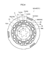
Fig. 4 is a cross-sectional view in a direction orthogonal to the axial direction of the brake portion ofFig. 3 ; -
Fig. 5 is a front view in which the brake portion ofFig. 3 is seen from the axial direction; -
Fig. 6 is an enlarged view of the portion indicated byarrow 6 inFig. 4 ; -
Fig. 7 is an enlarged view that corresponds toFig. 6 and shows the state of the brake portion at the time of the raising operation of a seat cushion; -
Fig. 8 is an enlarged view that corresponds toFig. 6 and shows the state of the brake portion at the time of the lowering operation of the seat cushion; -
Fig. 9 is an exploded perspective view of a brake portion of a lifter device that is used in a seat lifter structure relating to a second embodiment; -
Fig. 10 is a cross-sectional view in a direction orthogonal to the axial direction of the brake portion ofFig. 9 ; -
Fig. 11 is a front view in which the brake portion ofFig. 9 is seen from the axial direction; -
Fig. 12 is an enlarged view of the portion indicated byarrow 12 inFig. 10 ; -
Fig. 13 is an enlarged view that corresponds toFig. 12 and shows the state of the brake portion at the time of the raising operation of the seat cushion; and -
Fig. 14 is an enlarged view that corresponds toFig. 12 and shows the state of the brake portion at the time of the lowering operation of the seat cushion. - A
seat lifter structure 20 relating to a first embodiment of the present invention, and aseat 22 for a vehicle (an automobile in the present embodiment) that is provided with theseat lifter structure 20, are described hereinafter on the basis ofFig. 1 through Fig. 8 . Note that arrow FR in the drawings indicates the forward direction of theseat 22, arrow UP indicates the upward direction of theseat 22, and arrow W indicates the transverse direction of theseat 22. Further, the forward, upward and transverse directions ofseat 22 correspond respectively to the forward, upward and transverse directions of the vehicle (the automobile) to which theseat 22 is applied. Hereinafter, when merely longitudinal direction, vertical direction and transverse directions are used, they mean the respective directions that are based on the seat 22 (the vehicle body of the automobile). - As shown in
Fig. 1 , theseat 22 has aseat cushion 24 on which a vehicle occupant (a seated person) sits, aseat back 26 for supporting the back of the vehicle occupant, and unillustrated reclining mechanism, aseat sliding mechanism 28, and theseat lifter structure 20. - The
seat cushion 24 has aseat cushion frame 30 that is the skeleton. Theseat cushion 24 is formed by apad 32 being mounted to theseat cushion frame 30 and being covered from above by askin 34. - The seat back 26 has an unillustrated seat back frame that is the skeleton. The seat back 26 is formed by a
pad 36 being mounted to the seat back frame and being covered from above by askin 38. - The reclining mechanism is provided between the
seat cushion 24 and the seat back 26, and connects the seat back frame and the rear end portion of theseat cushion frame 30. This reclining mechanism is a conventional, well-known mechanism, and makes it possible to adjust the angle of tilting of the seat back 26 with respect to theseat cushion 24 in several stages. - The
seat sliding mechanism 28 is provided beneath theseat cushion 24, and supports theseat cushion 24 via alink mechanism 46 that is described later. Thisseat sliding mechanism 28 haslower rails 42 that are fixed to avehicle body floor 40,upper rails 44 that are supported (guided) so as to be able to slide in the seat longitudinal direction with respect to thelower rails 42, and an unillustrated locking mechanism that locks the sliding of theupper rails 44 with respect to the lower rails 42. Theseat sliding mechanism 28 makes it possible to adjust the position of theseat cushion 24 and the seat back 26 with respect to thevehicle body floor 40 in the seat longitudinal direction. - The
seat lifter structure 20 has thelink mechanism 46 that makes it possible to move theseat cushion 24 in the vertical direction with respect to thevehicle body floor 40, and alifter device 48 that transmits operational force (rotational force), by which the vehicle occupant operates anoperation lever 62 that is described later, to thelink mechanism 46. - The
link mechanism 46 has frontside link members 50 and rearside link members 52 that connect theseat cushion frame 30 and the upper rails 44. - The upper end of the front
side link member 50 is connected by a link shaft (link pin) 50A to afront portion 30A of theseat cushion frame 30 so as to be able to rotate around thelink shaft 50A. On the other hand, the lower end of the frontside link member 50 is connected by alink shaft 50B to afront portion 44A of theupper rail 44 so as to be able to rotate around thelink shaft 50B. - The upper end of the rear
side link member 52 is connected by alifter rod 54 to arear portion 30B of theseat cushion frame 30 so as to be able to rotate around thelifter rod 54. On the other hand, the lower end of the rearside link member 52 is connected by alink shaft 52A to arear portion 44B of theupper rail 44 so as to be able to rotate around thelink shaft 52A. Thelifter rod 54 connects the pair of rearside link members 52, that are provided at the seat transverse direction both sides, so as to synchronize the operations of the pair of rearside link members 52. - By the
upper rail 44, the frontside link member 50, theseat cushion frame 30 and the rearside link member 52, thelink mechanism 46 structures a 4-joint link in which theupper rail 44 is made to be a fixed link. The range between a posture in which the frontside link member 50 and the rearside link member 52 are tilted rearward at a predetermined angle, and a posture in which the frontside link member 50 and the rearside link member 52 are substantially upright, is the range of operation of thelink mechanism 46. Thelink mechanism 46 makes it possible to move theseat cushion 24 in the vertical direction with respect to thevehicle body floor 40, by operation (swinging) of the frontside link member 50 and the rearside link member 52. Namely, thelink mechanism 46 makes it possible to adjust the vertical direction position (the height) of theseat cushion 24. - A
lifter gear 56 is provided integrally with the rearside link member 52. Thelifter gear 56 is formed substantially in the shape of a fan-shaped plate at which anouter tooth 56A is formed along a circular arc around thelifter rod 54. Thelifter gear 56 extends forward from the upper portion of the rearside link member 52, such that theouter tooth 56A is positioned at the front side with respect to thelifter rod 54. Further, theouter tooth 56A of thelifter gear 56 meshes-together with apinion gear 60 that is provided at anoutput shaft 58 of thelifter device 48. Therefore, when theoutput shaft 58 rotates, the rotational force of theoutput shaft 58 is transmitted from thepinion gear 60 via thelifter gear 56 to the rearside link member 52. - As shown in
Fig. 2 , when theoutput shaft 58 rotates in a first direction (the arrow A direction inFig. 2 ) around the axis, the rearside link member 52 tilts rearward (rotates in the arrow B direction inFig. 2 ), and, accompanying this, the frontside link member 50 also tilts rearward, and theseat cushion 24 moves downward (falls). On the other hand, when theoutput shaft 58 rotates in a second direction (the arrow C direction inFig. 2 ), the rearside link member 52 stands-up (rotates in the arrow D direction inFig. 2 ), and, accompanying this, the frontside link member 50 also stands-up, and theseat cushion 24 moves upward (rises). - The
lifter device 48 is mounted to a seat transverse direction side surface of the seat cushion 24 (the seat cushion frame 30). Thislifter device 48 is structured by an unillustrated force converting section that converts the swinging operation of theoperation lever 62 that the vehicle occupant operates (the swinging operation in the arrow E direction and the arrow F direction inFig. 2 ) into rotational force, and abrake portion 64 that transmits to thelink mechanism 46 the rotational force obtained by conversion at the force converting section, and cuts-off reverse input from the link mechanism 46 (rotational force in the opposite direction). - The force converting section of the
lifter device 48 is a structure that converts operation, at the time when theoperation lever 62 is pushed-down (swinging operation in the arrow E direction inFig. 2 ) from a neutral position (the position of the state shown inFig. 1 orFig. 2 ) or pulled-up (swinging operation in the arrow F direction inFig. 2 ) from the neutral position, into rotational force, and does not convert operation, at the time when theoperation lever 62 returns to the neutral position, into rotational force. Note that, due to the operation of pushing theoperation lever 62 down from the neutral position, theoutput shaft 58, together with aninput shaft 66 that is described later, rotates in the first direction. Due to the operation of pulling theoperation lever 62 up from the neutral position, theoutput shaft 58, together with theinput shaft 66 that is described later, rotates in the second direction. - As shown in
Fig. 3 through Fig. 5 , thebrake portion 64 has: theinput shaft 66 to which is received the rotational force obtained by conversion at the force converting section; theoutput shaft 58 that is connected to theinput shaft 66, and rotates in the same direction as the direction in which theinput shaft 66 rotates, and that transmits rotational force to thelink mechanism 46; alocking mechanism 68 that permits the transmission of rotational force from theinput shaft 66 to theoutput shaft 58 and cuts-off reverse input from theoutput shaft 58 to the input shaft; afriction ring 70 that serves as an example of a friction member and is fixed to theseat cushion frame 30; andsliders 72 that are provided at theoutput shaft 58 andstructure abutting portions 72A that, when theinput shaft 66 rotates in the first direction, abut an outerperipheral surface 70A that serves as a friction surface of thefriction ring 70. Further, as shown inFig. 3 , in the present embodiment, the axis of theinput shaft 66 and the axis of theoutput shaft 58 coincide, i.e., theinput shaft 66 and theoutput shaft 58 are disposed on the same axis. - As shown in
Fig. 3 , theinput shaft 66 has: atubular portion 66A in which ashaft portion 58A of theoutput shaft 58 is inserted; an overhangingportion 66B that is annular and juts-out toward the radial direction outer side from an axial direction one end portion (inFig. 3 , the end portion at a fixedplate 82 side that is described later) of thetubular portion 66A; and anenlarged diameter portion 66C that extends from the outer peripheral edge portion of the overhangingportion 66B toward an axial direction one side (inFig. 3 , the fixedplate 82 side that is described later). - Plural (eight in the present embodiment) notches, that are concave from the one end portion in the axial direction toward the other end portion side, are formed at the
enlarged diameter portion 66C at an interval (in the present embodiment, a uniform interval) in the peripheral direction. These notched portions are made to bepocket portions 66D (seeFig. 4 ) that holdtubular rollers 74 and plate springs 76 that are described later and that structure thelocking mechanism 68. Note that, in the present embodiment, thepocket portions 66D are formed by notching theenlarged diameter portion 66C from the axial direction one end portion all the way to the overhangingportion 66B. However, the present invention is not limited to this structure, and, provided that thepocket portions 66D can accommodate and hold thetubular rollers 74 and the plate springs 76, thepocket portions 66D may be formed by notching theenlarged diameter portion 66C from the axial direction one end portion until just before reaching the overhangingportion 66B. Further, there may be a structure in which, without notching theenlarged diameter portion 66C, opening portions are formed at an interval in the peripheral direction in theenlarged diameter portion 66C, and thetubular rollers 74 and the plate springs 76 are accommodated and held in these opening portions. - Through-
holes 67, that pass through the overhangingportion 66B in the axial direction, are formed at the overhangingportion 66B at the periphery of thetubular portion 66A at an interval (in the present embodiment, a uniform interval) in the peripheral direction. These through-holes 67 are long holes whose lengths along the peripheral direction of theinput shaft 66 are the length directions thereof, and projectingportions 59 of theoutput shaft 58 that are described later are inserted therein (seeFig. 5 ). - The
output shaft 58 has: theshaft portion 58A; an overhangingportion 58B that is annular and that juts-out toward the radial direction outer side from an axial direction intermediate portion of theshaft portion 58A; and anenlarged diameter portion 58C that extends from the outer peripheral edge portion of the overhangingportion 58B toward an axial direction one side (inFig. 3 , the fixedplate 82 side), and that is inserted into the radial direction inner side of theenlarged diameter portion 66C of theinput shaft 66. - The
pinion gear 60 is formed at the axial direction one end portion (inFig. 3 , the end portion at the fixedplate 82 side) of theshaft portion 58A. The axial direction other end portion of theshaft portion 58A is inserted in thetubular portion 66A. - The outer peripheral surface of the
enlarged diameter portion 58C is structured by plural (e.g., eight) cam surfaces 58D (seeFig. 4 ) that are flat and are formed at a uniform interval in the peripheral direction. Between thesecam surfaces 58D and an innerperipheral surface 78A of anouter ring 78 that is described later, there are formed gaps 80 (seeFig. 4 ) that are shaped such that the lengths thereof from the cam surfaces 58D to the innerperipheral surface 78A become longer from the both ends of the cam surfaces 58D toward the centers. Two of thetubular rollers 74 and one of the plate springs 76 are disposed in each of thegaps 80. - Further, plural (eight in the present embodiment) notches, that are concave from the axial direction one end portion toward the other end portion side, are formed at the
enlarged diameter portion 58C at an interval (in the present embodiment, a uniform interval) in the peripheral direction, at the boundary portions between the cam surfaces 58D that are adjacent one another. These notched portions arepocket portions 58E that are for accommodating and holding the sliders 72 (seeFig. 4 ). Note that, in the present embodiment, thepocket portions 58E are formed by notching theenlarged diameter portion 58C from the axial direction one end portion all the way to the overhangingportion 58B. However, the present invention is not limited to this structure, and, provided that thepocket portions 58E can accommodate and hold thesliders 72, thepocket portions 58E may be formed by notching theenlarged diameter portion 58C from the axial direction one end portion until just before reaching the overhangingportion 58B. Further, there may be a structure in which, without notching theenlarged diameter portion 58C, opening portions are formed at an interval in the peripheral direction in theenlarged diameter portion 58C, and thesliders 72 are accommodated and held in these opening portions. - The projecting
portions 59, that project-out in the axial direction from the overhangingportion 58B, are formed at the overhangingportion 58B at the periphery of theshaft portion 58A at an interval (in the present embodiment, a uniform interval) in the peripheral direction. The projectingportions 59 are inserted in the through-holes 67 of theinput shaft 66, and theinput shaft 66 and theoutput shaft 58 are connected. Note that, as shown inFig. 4 andFig. 5 , in the state in which rotational force is not being imparted to the input shaft 66 (an unloaded state), plate-shapedportions 66E that structure theenlarged diameter portion 66C of theinput shaft 66 are disposed at the radial direction outer sides of thepocket portions 58E of theoutput shaft 58. - As shown in
Fig. 3 , thebrake member 64 has the fixingplate 82 that fixes thelifter device 48 to the side surface of theseat cushion frame 30, and theouter ring 78 that is annular and is fixed to the fixingplate 82. Because the fixingplate 82 and theouter ring 78 are fixed to theseat cushion frame 30, the fixingplate 82 and theouter ring 78 are in static states (non-rotating states) with respect to theinput shaft 66 and theoutput shaft 58 that rotate with respect to the seat cushion frame 30 (the seat cushion 24). Further, thefriction ring 70 also is fixed to the fixingplate 82, and is in a static state with respect to theinput shaft 66 and theoutput shaft 58. - A through-
hole 82A, through which theshaft portion 58A of theoutput shaft 58 passes, is formed at the central portion of the fixingplate 82. Further, plural (three in the present embodiment) mountingholes 82B are formed at intervals in the outer peripheral edge portion of the fixingplate 82. Unillustrated bolts are passed-through the mountingholes 82B, and the fixingplate 82 is fixed to the side surface of theseat cushion frame 30. Further, plural through-holes 82C are formed at the periphery of the through-hole 82A of the fixingplate 82 at an interval (in the present embodiment, a uniform interval) around the through-hole 82A. Unillustrated projecting portions, that are formed at the side surface of the friction ring 70 (the side surface at the fixingplate 82 side), are inserted (press-fit) into these through-holes 82C. The projecting portions are inserted into the through-holes 82C, and thefriction ring 70 is fixed to the fixingplate 82. - Plural (three in the present embodiment) notched portions 78B that are concave are formed at the outer peripheral edge portion of the
outer ring 78.Claw portions 82D, that are formed at the outer peripheral edge portion of the fixingplate 82, are fit into these notched portions 78B, and theouter ring 78 is fixed to the fixingplate 82. Note that, in the present embodiment, theenlarged diameter portion 66C of theinput shaft 66, theenlarged diameter portion 58C of theoutput shaft 58, thefriction ring 70, thetubular rollers 74 and the plate springs 76 are disposed at the radial direction inner side of theouter ring 78. - The
friction ring 70 is annular, and is disposed at the radial direction inner side of theenlarged diameter portion 58C of theoutput shaft 58, and is fixed to the fixing plate 82 (seeFig. 3 andFig. 4 ). As shown inFig. 8 , due to the abuttingportions 72A that are the distal end portions of thesliders 72 abutting the outerperipheral surface 70A of thefriction ring 70, thefriction ring 70 generates frictional force between the outerperipheral surface 70A and the abuttingportions 72A, and can impart rotational resistance to theoutput shaft 58. - The
locking mechanism 68 has the pairs oftubular rollers 74 that are disposed in thegaps 80, and the plate springs 76 that are disposed between the pairs oftubular rollers 74 and apply separating force to the bothtubular rollers 74. Note that N-shaped plate springs are used as the plate springs 76 in the present embodiment. However, the shape of the plate springs is not limited, provided that the plate spring can, between the pair oftubular rollers 74, impart separating force to the bothtubular rollers 74. For example, plate springs that are M-shaped may be used. - As shown in
Fig. 6 , in the state in which rotational force is not imparted to theinput shaft 66, due to the separating force of theplate spring 76, the twotubular rollers 74 respectively abut the innerperipheral surface 78A of theouter ring 78 and end portion sides of thecam surface 58D of theoutput shaft 58, that form thegap 80, and rotation of theoutput shaft 58 is locked. In this state, the transmission of reverse input from theoutput shaft 58 to theinput shaft 66 is cut-off. On the other hand, as shown inFig. 7 andFig. 8 , when rotational force is imparted (transmitted) to theinput shaft 66, onetubular roller 74 among the twotubular rollers 74 is pushed by the plate-shapedportion 66E that structures theenlarged diameter portion 66C, and approaches the othertubular roller 74 while elastically deforming theplate spring 76. At this time, because the onetubular roller 74 moves on thecam surface 58D, as the onetubular roller 74 approaches the othertubular roller 74, the onetubular roller 74 moves away from the innerperipheral surface 78A of theouter ring 78, and locking of theoutput shaft 58 is released. Further, a length direction end portion of the through-hole 67 of theinput shaft 66 and the projectingportion 59 of theoutput shaft 58 abut one another, and rotational force is transmitted from theinput shaft 66 to theoutput shaft 58. - The
sliders 72 are accommodated and held in thepocket portions 58E of theoutput shaft 58, and can move in directions of approaching and moving away from the outerperipheral surface 70A of thefriction ring 70. Concretely, thesliders 72 can move in the radial direction of theoutput shaft 58. Further, because thesliders 72 are accommodated and held in thepocket portions 58E, theplural sliders 72 are disposed at the outer peripheral side of thefriction ring 70 at an interval in the peripheral direction of thefriction ring 70. - Further, when the
slider 72 is pushed by the plate-shapedportion 66E of theinput shaft 66 that rotates in the first direction, theslider 72 approaches the outerperipheral surface 70A of thefriction ring 70, and the abuttingportion 72A abuts the outerperipheral surface 70A. Concretely, as shown inFig. 6 through Fig. 8 , aninclined portion 84, that is inclined such that the height of an outerperipheral surface 72B becomes higher while heading toward the first direction, is formed at the outerperipheral surface 72B of theslider 72. On the other hand, an oppositelyinclined portion 86, that is inclined in the direction opposite theinclined portion 84, is formed at the inner peripheral surface of the plate-shapedportion 66E of theinput shaft 66. Note that "the outerperipheral surface 72B of theslider 72 becomes higher" here means that the distance from the axis of theoutput shaft 58 becomes longer. - Operation and effects of the
seat lifter structure 20 of the present embodiment are described next. - At the
seat lifter structure 20, when operational force is received from a seated person via theoperation lever 62 and theinput shaft 66 rotates in the first direction around the axis, as shown inFig. 8 , one of the tubular rollers 74 (thetubular roller 74 at the first direction side of the plate-shapedportion 66E inFig. 8 ) of the twotubular rollers 74 that are disposed within thegap 80 is pushed by the plate-shapedportion 66E of theinput shaft 66, and the locked state is released. At this time, theslider 72 is pushed by the plate-shapedportion 66E and approaches thefriction ring 70, and the abuttingportion 72A that is the distal end portion abuts the outerperipheral surface 70A. Further, theoutput shaft 58 rotates in the first direction together with theinput shaft 66, in a state in which frictional force is generated between the abuttingportion 72A and the outerperipheral surface 70A. When theoutput shaft 58 rotates in the first direction, rotational force is transmitted from thepinion gear 60 via theouter tooth 56A of thelifter gear 56 to the link mechanism 46 (the rear side link member 52), and theseat cushion 24 is lowered with respect to thevehicle body floor 40. - Here, when the
input shaft 66 is rotated in the first direction in order to lower theseat cushion 24, because the abuttingportions 72A of thesliders 72 abut the outerperipheral surface 70A of thefriction ring 70, relative rotation in the first direction of theoutput shaft 58 with respect to theinput shaft 66 due to the weights of the seated person and the seat (here, the seat main body that is structured by theseat cushion 24 and the seat back 26) is suppressed by the frictional force that arises between the abuttingportions 72A and the outerperipheral surface 70A. Namely, at the time of the lowering operation of the seat cushion 24 (at the time of the operation of rotating theinput shaft 66 in the first direction), relative rotation of theoutput shaft 58 with respect to theinput shaft 66 due to the weights of the seat and the seated person can be suppressed. - Further, in the above-described seat lifter structure, when operational force is received from a seated person via the
operation lever 62 and theinput shaft 66 rotates in the second direction around the axis, as shown inFig. 7 , the other tubular roller 74 (thetubular roller 74 at the second direction side of the plate-shapedportion 66E inFig. 7 ) of the twotubular rollers 74 that are disposed within thegap 80 is pushed by the plate-shapedportion 66E of theinput shaft 66, and the locked state is released, and theoutput shaft 58 rotates together with theinput shaft 66. When theoutput shaft 58 rotates in the second direction, rotational force is transmitted from thepinion gear 60 via theouter tooth 56A of thelifter gear 56 to the link mechanism 46 (the rear side link member 52), and theseat cushion 24 is raised with respect to thevehicle body floor 40. - Here, even if the
input shaft 66 is rotated in the second direction in order to raise theseat cushion 24, the abuttingportions 72A of thesliders 72 do not abut the outerperipheral surface 70A of thefriction ring 70, or are not pushed by the plate-shapedportions 66E of theinput shaft 66. Therefore, frictional force is not generated between the abuttingportions 72A and the outerperipheral surface 70A, and the operational force at the time of the raising operation of the seat cushion 24 (at the time of the operation of rotating theinput shaft 66 in the second direction) can be reduced. - Further, at the
seat lifter structure 20, at the time of the lowering operation of theseat cushion 24, frictional force is generated substantially continuously between theoutput shaft 58 that rotates in the first direction and thefriction ring 70 that is fixed to theseat cushion 24. Therefore, stable frictional force can be ensured. Accordingly, at the time of the lowering operation of theseat cushion 24, relative rotation of theoutput shaft 58 with respect to theinput shaft 66 due to the weights of the seat and the seated person can be suppressed more. - Moreover, in the
seat lifter structure 20, at the time of the lowering operation of theseat cushion 24, the oppositely inclinedportions 86 of the plate-shapedportions 66E of theinput shaft 66 contact theinclined portions 84 of thesliders 72, and some of the rotational force of theinput shaft 66 is converted into moving force that causes thesliders 72 to approach the outerperipheral surface 70A of thefriction ring 70. In this way, the rotational force of theinput shaft 66 can be converted into moving force of thesliders 72 by the simple structure for forming theinclined portions 84 at thesliders 72 and forming the oppositely inclinedportions 86 at the plate-shapedportions 66E of theinput shaft 66. - Still further, in the
seat lifter structure 20, theplural sliders 72 are disposed at the outer peripheral side of thefriction ring 70 at an interval in the peripheral direction of thefriction ring 70. Therefore, wear of therespective sliders 72 can be reduced while the frictional force that is generated between theoutput shaft 58 and thefriction ring 70 is ensured. - In the first embodiment, the
plural pocket portions 58E are formed at theoutput shaft 58. However, the present invention is not limited to this structure, and there may be a structure in which one of thepocket portions 58E is formed at theoutput shaft 58, and, at the time of the lowering operation of theseat cushion 24, frictional force is generated between thefriction ring 70 and theslider 72 that is accommodated and held in thispocket portion 58E. - A
seat lifter structure 90 relating to a second embodiment of the present invention is described next with reference toFig. 9 through Fig. 14 . Note that structures that are similar to those of the first embodiment are denoted by the same reference numerals, and description thereof is omitted as appropriate. - As shown in
Fig. 9 , in theseat lifter structure 90 of the present embodiment, structures other than abrake portion 93 of alifter device 92 are similar to those of theseat lifter structure 20 of the first embodiment. - The
brake portion 93 has theinput shaft 66, anoutput shaft 94, thelocking mechanism 68, thefriction ring 70, theouter ring 78, the fixingplate 82, and plate springs 96 that serve as friction members and that are fixed to the wall surfaces of the through-holes 67 of theinput shaft 66. Note that this is a structure in which theinclined portions 84 of the first embodiment are not formed at the plate-shapedportions 66E of theinput shaft 66 of the present embodiment (refer toFig. 12 ). - The
output shaft 94 has ashaft portion 94A and an overhangingportion 94B that juts-out toward the radial direction outer side from an axial direction intermediate portion of theshaft portion 94A. - The
pinion gear 60 is formed at one end portion (inFig. 9 , the end portion at the fixedplate 82 side) in the axial direction of theshaft portion 94A. The axial direction other end portion of theshaft portion 94A is inserted in thetubular portion 66A. - The outer peripheral surface of the overhanging
portion 94B is structured by plural (e.g., eight) cam surfaces 94C (seeFig. 10 ) that are flat and that are formed at a uniform interval in the peripheral direction. Gaps 98 (seeFig. 10 ), that are shaped such that the lengths thereof from the cam surfaces 94C to the innerperipheral surface 78A become longer from the both ends of the cam surfaces 94C toward the centers, are formed between these cam surfaces 94C and the innerperipheral surface 78A of theouter ring 78. Two of thetubular rollers 74 and one of the plate springs 76 are disposed in each of thegaps 98. - Further, projecting
portions 95, that project-out in the axial direction from the overhangingportion 94B, are formed at the overhangingportion 94B at the periphery of theshaft portion 94A at an interval (in the present embodiment, a uniform interval) in the peripheral direction. These projectingportions 95 are inserted into the through-holes 67 of theinput shaft 66, and theinput shaft 66 and theoutput shaft 58 are connected. Note that, as shown inFig. 10 andFig. 11 , in the state in which rotational force is not being imparted to the input shaft 66 (an unloaded state), the plate-shapedportions 66E of theinput shaft 66 are disposed at the radial direction outer sides of the boundary portions of the adjacent cam surfaces 94C of the output shaft 94 (seeFig. 12 ). - As shown in
Fig. 12 , the plate springs 96 are provided in convex shapes atwall surfaces 67A of a length direction intermediate portion of the through-hole 67. Concretely, the length direction both ends of the plate springs 96 are fixed to the wall surfaces 67A, and the length direction intermediate portions are curved in convex shapes in directions of moving away from the wall surfaces 67A. Further, in the present embodiment, the plate springs 96 are provided respectively at facing portions of the through-hole 67, and the interval between the both is smaller than the outer diameter of the projectingportion 95. Therefore, in the present embodiment, when theinput shaft 66 rotates in the first direction, the projectingportion 95 moves, with respect to theinput shaft 66, to a seconddirection end portion 67B side of the through-hole 67, and is nipped by theend portion 67B of the through-hole 67 and the plate springs 96. Note that, in the present embodiment, there is a structure in which two of the plate springs 96 are provided at the one through-hole 67. However, the present invention is not limited to this structure, and may be a structure in which one of the plate springs 96 is provided in one of the through-holes 67. In a case in which oneplate spring 96 is provided in one through-hole 67, by making the interval between an outerperipheral surface 96A of theplate spring 96 and the facingwall surface 67A be smaller than the outer diameter of the projectingportion 95, in the same way as a case in which two of the plate springs 96 are provided, when theinput shaft 66 rotates in the first direction, the projectingportion 95 moves, with respect to theinput shaft 66, to the seconddirection end portion 67B side of the through-hole 67, and the projectingportion 95 is nipped by theend portion 67B of the through-hole 67 and theplate spring 96. - Operation and effects of the
seat lifter structure 90 of the present embodiment are described next. - In the
seat lifter structure 90, as shown inFig. 14 , at the time of the lowering operation of theseat cushion 24, in the state in which the projectingportion 95 of theoutput shaft 94 has moved (moved relatively) toward theend portion 67B side of the through-hole 67 with respect to theinput shaft 66 and is nipped by theend portion 67B of the through-hole 67 and the plate springs 96, theoutput shaft 94 rotates in the first direction together with theinput shaft 66. Here, even if theoutput shaft 94 attempts to rotate in the first direction relative to theinput shaft 66 due to the weights of the seat and the seated person, because an abutting portion 95A that is the outer peripheral surface of the projectingportion 95 is abutting the outerperipheral surfaces 96A of the plate springs 96 that are elastically deformable, relative rotation of theoutput shaft 94 in the first direction with respect to theinput shaft 66 is suppressed by the frictional force that is generated between the abutting portion 95A of the projectingportion 95 and the outerperipheral surfaces 96A. In this way, frictional force can be generated between the projectingportions 95 and the outerperipheral surfaces 96A of the plate springs 96 as described above, by the simple structure of providing the plate springs 96 at the wall surfaces 67A of the through-holes 67 of theinput shaft 66 and providing the projectingportions 95 at theoutput shaft 94. - Note that an unillustrated spring for returning the
operation lever 62 to its original position is provided at thelifter device 92. Therefore, in the state in which theoperation lever 62 is not operated, the projectingportions 95 return to the length direction central portions of the through-holes 67 due to the elastic force of the spring that returns theoperation lever 62 to its original position. - Further, at the time of the raising operation of the
seat cushion 24, the projectingportions 95 of theoutput shaft 94 move, with respect to theinput shaft 66, to endportion 67C sides of the through-holes 67 (seeFig. 13 ). Further, rotational force is transmitted from theinput shaft 66 to theoutput shaft 94 via the projectingportions 95 that abut theend portions 67C of the through-holes 67. - Further, the
seat lifter structure 90 uses, as the friction member, theplate spring 96 whose length direction both ends are fixed to thewall surface 67A of the through-hole 67 and whose length direction intermediate portion is curved in a convex shape. Therefore, theoutput shaft 58 rotating in the first direction relative to theinput shaft 66 due to the weights of the seat and the seated person can be suppressed by a simple structure. - Moreover, in the
seat lifter structure 90, the plate springs 96 are respectively provided at facing portions of the wall surfaces 67A of the through-hole 67, and moreover, the interval between the facing plate springs 96 is made to be smaller than the outer diameter of the projectingportion 95. Therefore, at the time of the lowering operation of theseat cushion 24, the frictional force that is generated due to the projectingportion 95 abutting the outerperipheral surfaces 96A of the plate springs 96 is increased. - In the second embodiment, the
plate spring 96, that is provided at thewall surface 67A of the through-hole 67 and that is curved in a convex shape, is made to be the friction member of the present invention, but the present invention is not limited to this structure. For example, a projecting member that projects-out freely from thewall surface 67A may be used as the friction member of the present invention. Concretely, at the time of the lowering operation of theseat cushion 24, the projectingportion 95 can be nipped by theend portion 67B of the through-hole 67 and theplate spring 96 by inserting and placing an urging member (e.g., a coil spring) and a projecting member, whose outer peripheral surface is curved in a circular arc shape, within a concave portion that is formed at thewall surface 67A, and causing the outer peripheral surface of the projecting member to project-out from thewall surface 67A due to the urging force of the urging member. Note that, at the time when the projectingportion 95 returns to the length direction central portion of the through-hole 67 due to the elastic force of the spring that returns theoperation lever 62 to its original position, the aforementioned projecting member is pushed by the projectingportion 95 into the concave portion, and the projectingportion 95 passes thereon. - Although embodiments of the present invention have been described above, the present invention is not limited to the above description, and, of course, can be embodied by being modified in various ways other than the above within a scope that does not depart from the gist thereof.
Claims (6)
- A seat lifter structure (20) characterized in that it comprises:an input shaft (66) that is rotatably provided at a seat cushion (24) of a seat (22) that is set on a vehicle body floor (40), and that rotates around an axis when operational force is received from a seated person;an output shaft (58) that is connected to the input shaft (66), and that, when the input shaft (66) rotates, rotates in a same direction as the input shaft (66);a link mechanism (46) that is provided between the vehicle body floor (40) and the seat cushion (24), and is connected to the output shaft (58), when the output shaft (58) rotates in a first direction, the link mechanism (46) moving the seat cushion (24) downward in a vehicle body vertical direction with respect to the vehicle body floor (40), and when the output shaft (58) rotates in a second direction that is opposite to the first direction, the link mechanism (46) moving the seat cushion (24) upward in the vehicle body vertical direction with respect to the vehicle body floor (40); andan abutting portion (72A) that is provided at the output shaft (58), and that, when the input shaft (66) rotates in the first direction, abuts a friction surface that is provided at the seat cushion (24) or the input shaft (66).
- The seat lifter structure (20) of claim 1, wherein
the friction surface is an outer peripheral surface (70A) of a friction member (70) that is annular and is fixed to the seat cushion (24),
the abutting portion (72A) is structured by a moving member (72) that is provided at the output shaft (58) and moves in directions of approaching and moving away from the friction surface, and
an outer peripheral surface (72B) of the moving member (72) is pushed by a portion of the input shaft (66) that rotates in the first direction, and approaches the friction surface. - The seat lifter structure (20) of claim 2, wherein
an inclined portion (84), that is inclined such that a height of the outer peripheral surface (72B) of the moving member (72) becomes higher while heading in the first direction, is formed at the outer peripheral surface (72B) of the moving member (72), and
an oppositely inclined portion (86), that is inclined in a direction opposite the inclined portion (84), is formed at a portion of the input shaft (66) which portion contacts the inclined portion. - The seat lifter structure (20) of claim 2 or claim 3, wherein a plurality of the moving members (72) are disposed at an outer peripheral side of the friction member (70) at an interval in a peripheral direction of the friction member (70).
- The seat lifter structure (20) of claim 1, wherein
a through-hole (67), that passes-through in an axial direction of the input shaft (66) and whose length direction is a rotating direction of the input shaft, is formed at the input shaft (66),
the friction surface is an outer peripheral surface of a friction member that is elastically deformable and is provided in a convex shape at a wall surface of a length direction intermediate portion of the through-hole (67),
the abutting portion is structured by a projecting portion (95) that is cylindrical and projects-out in an axial direction of the output shaft (58) and is inserted in the through-hole (67), and
when the input shaft (66) rotates in the first direction, the projecting portion (95) moves, with respect to the input shaft (66), to a second direction end portion (67B) side of the through-hole (67), and is nipped by the friction member and the second direction end portion (67B) of the through-hole (67). - The seat lifter structure (20) of claim 5, wherein the friction member is a plate spring (96) whose length direction both ends are fixed to the wall surface of the length direction intermediate portion of the through-hole (67), and whose length direction intermediate portion is curved in a convex shape.
Applications Claiming Priority (1)
| Application Number | Priority Date | Filing Date | Title |
|---|---|---|---|
| JP2014238222A JP6149848B2 (en) | 2014-11-25 | 2014-11-25 | Seat lifter structure |
Publications (2)
| Publication Number | Publication Date |
|---|---|
| EP3042801A1 true EP3042801A1 (en) | 2016-07-13 |
| EP3042801B1 EP3042801B1 (en) | 2017-09-27 |
Family
ID=54251410
Family Applications (1)
| Application Number | Title | Priority Date | Filing Date |
|---|---|---|---|
| EP15187726.3A Not-in-force EP3042801B1 (en) | 2014-11-25 | 2015-09-30 | Seat lifter structure |
Country Status (2)
| Country | Link |
|---|---|
| EP (1) | EP3042801B1 (en) |
| JP (1) | JP6149848B2 (en) |
Cited By (1)
| Publication number | Priority date | Publication date | Assignee | Title |
|---|---|---|---|---|
| JP2020147267A (en) * | 2019-03-08 | 2020-09-17 | トヨタ紡織株式会社 | Lifter device |
Families Citing this family (4)
| Publication number | Priority date | Publication date | Assignee | Title |
|---|---|---|---|---|
| JP7087672B2 (en) * | 2018-05-24 | 2022-06-21 | トヨタ紡織株式会社 | Lifter device |
| JP7135945B2 (en) * | 2019-03-08 | 2022-09-13 | トヨタ紡織株式会社 | Lifter device |
| JP7259712B2 (en) * | 2019-11-20 | 2023-04-18 | トヨタ紡織株式会社 | Lifter device |
| KR102731314B1 (en) * | 2022-04-21 | 2024-11-15 | 대원강업주식회사 | Slide Locking Device |
Citations (4)
| Publication number | Priority date | Publication date | Assignee | Title |
|---|---|---|---|---|
| EP1308643A1 (en) * | 2000-08-08 | 2003-05-07 | Ntn Corporation | Clutch unit |
| US20070137965A1 (en) * | 2005-12-21 | 2007-06-21 | Aisin Seiki Kabushiki Kaisha | Seat adjusting apparatus for vehicle |
| JP2007261388A (en) | 2006-03-28 | 2007-10-11 | Toyota Motor Corp | Support structure for vehicle seat |
| WO2014021582A1 (en) * | 2012-07-30 | 2014-02-06 | Km&I.Co.,Ltd | Pumping device for adjusting seat height and apparatus for adjusting seat height for motor vehicle having the same |
Family Cites Families (7)
| Publication number | Priority date | Publication date | Assignee | Title |
|---|---|---|---|---|
| JP4278844B2 (en) * | 2000-08-08 | 2009-06-17 | Ntn株式会社 | Clutch unit |
| JP2003294060A (en) * | 2002-03-29 | 2003-10-15 | Ntn Corp | Reversed input breaking clutch |
| JP4940650B2 (en) * | 2005-12-21 | 2012-05-30 | アイシン精機株式会社 | Vehicle seat adjustment device |
| JP4940653B2 (en) * | 2005-12-22 | 2012-05-30 | アイシン精機株式会社 | Vehicle seat adjustment device |
| US8292367B2 (en) * | 2006-09-26 | 2012-10-23 | Das Corporation | Pumping device for seat cushion of vehicle |
| US8678154B2 (en) * | 2010-05-03 | 2014-03-25 | Das Corporation | Apparatus for adjusting height of vehicle seat |
| JP2012158301A (en) * | 2011-02-02 | 2012-08-23 | Aisin Seiki Co Ltd | Seat lifter system for vehicle |
-
2014
- 2014-11-25 JP JP2014238222A patent/JP6149848B2/en not_active Expired - Fee Related
-
2015
- 2015-09-30 EP EP15187726.3A patent/EP3042801B1/en not_active Not-in-force
Patent Citations (4)
| Publication number | Priority date | Publication date | Assignee | Title |
|---|---|---|---|---|
| EP1308643A1 (en) * | 2000-08-08 | 2003-05-07 | Ntn Corporation | Clutch unit |
| US20070137965A1 (en) * | 2005-12-21 | 2007-06-21 | Aisin Seiki Kabushiki Kaisha | Seat adjusting apparatus for vehicle |
| JP2007261388A (en) | 2006-03-28 | 2007-10-11 | Toyota Motor Corp | Support structure for vehicle seat |
| WO2014021582A1 (en) * | 2012-07-30 | 2014-02-06 | Km&I.Co.,Ltd | Pumping device for adjusting seat height and apparatus for adjusting seat height for motor vehicle having the same |
Cited By (1)
| Publication number | Priority date | Publication date | Assignee | Title |
|---|---|---|---|---|
| JP2020147267A (en) * | 2019-03-08 | 2020-09-17 | トヨタ紡織株式会社 | Lifter device |
Also Published As
| Publication number | Publication date |
|---|---|
| JP2016097899A (en) | 2016-05-30 |
| EP3042801B1 (en) | 2017-09-27 |
| JP6149848B2 (en) | 2017-06-21 |
Similar Documents
| Publication | Publication Date | Title |
|---|---|---|
| EP3042801B1 (en) | Seat lifter structure | |
| US8820501B2 (en) | Pumping device for vehicle seat cushion | |
| US20080309136A1 (en) | Seat device for vehicle | |
| EP1905640A2 (en) | Seat device for vehicle | |
| JP5575573B2 (en) | Elevating mechanism for vehicle seat | |
| JP5949096B2 (en) | Ottoman equipment | |
| JP4735187B2 (en) | Vehicle seat adjustment device | |
| WO2014077389A1 (en) | Operating lever, seat device, and operating section structure | |
| JP2007126133A (en) | Adjustable lower seat to be used with upright/tilting backrest | |
| KR20200064261A (en) | Reclining device for vehicle seat | |
| EP2946758A1 (en) | Backrest assembly for wheelchair with reclining seat | |
| KR101787990B1 (en) | Reclining device for seat of vehicle | |
| JP6184275B2 (en) | Vehicle seat | |
| CN111200955A (en) | Chair with self-adjusting joint | |
| US20060061182A1 (en) | Seat for vehicle | |
| EP3691498A1 (en) | Oscillation system for chairs | |
| JP6588025B2 (en) | Rotation motion control mechanism and seat | |
| US9174558B2 (en) | Seat operating device and vehicle seat | |
| JP2018177018A (en) | Vehicle seat | |
| JP6150597B2 (en) | Seat device | |
| JP2004203252A (en) | Seat for vehicle | |
| US20060163925A1 (en) | Synchronizing mechanism | |
| JP4122444B2 (en) | Vehicle seat device | |
| EP3398808B1 (en) | Rotary seat with raisable footrest, in particular for railway vehicle | |
| JP5965705B2 (en) | Air suspension type seat support device for vehicles |
Legal Events
| Date | Code | Title | Description |
|---|---|---|---|
| PUAI | Public reference made under article 153(3) epc to a published international application that has entered the european phase |
Free format text: ORIGINAL CODE: 0009012 |
|
| 17P | Request for examination filed |
Effective date: 20150930 |
|
| AK | Designated contracting states |
Kind code of ref document: A1 Designated state(s): AL AT BE BG CH CY CZ DE DK EE ES FI FR GB GR HR HU IE IS IT LI LT LU LV MC MK MT NL NO PL PT RO RS SE SI SK SM TR |
|
| AX | Request for extension of the european patent |
Extension state: BA ME |
|
| GRAP | Despatch of communication of intention to grant a patent |
Free format text: ORIGINAL CODE: EPIDOSNIGR1 |
|
| STAA | Information on the status of an ep patent application or granted ep patent |
Free format text: STATUS: GRANT OF PATENT IS INTENDED |
|
| RIC1 | Information provided on ipc code assigned before grant |
Ipc: B60N 2/16 20060101AFI20170329BHEP |
|
| INTG | Intention to grant announced |
Effective date: 20170411 |
|
| GRAS | Grant fee paid |
Free format text: ORIGINAL CODE: EPIDOSNIGR3 |
|
| GRAA | (expected) grant |
Free format text: ORIGINAL CODE: 0009210 |
|
| STAA | Information on the status of an ep patent application or granted ep patent |
Free format text: STATUS: THE PATENT HAS BEEN GRANTED |
|
| AK | Designated contracting states |
Kind code of ref document: B1 Designated state(s): AL AT BE BG CH CY CZ DE DK EE ES FI FR GB GR HR HU IE IS IT LI LT LU LV MC MK MT NL NO PL PT RO RS SE SI SK SM TR |
|
| REG | Reference to a national code |
Ref country code: GB Ref legal event code: FG4D |
|
| REG | Reference to a national code |
Ref country code: CH Ref legal event code: EP |
|
| REG | Reference to a national code |
Ref country code: AT Ref legal event code: REF Ref document number: 931626 Country of ref document: AT Kind code of ref document: T Effective date: 20171015 |
|
| REG | Reference to a national code |
Ref country code: IE Ref legal event code: FG4D |
|
| REG | Reference to a national code |
Ref country code: FR Ref legal event code: PLFP Year of fee payment: 3 |
|
| REG | Reference to a national code |
Ref country code: DE Ref legal event code: R096 Ref document number: 602015004976 Country of ref document: DE |
|
| PG25 | Lapsed in a contracting state [announced via postgrant information from national office to epo] |
Ref country code: SE Free format text: LAPSE BECAUSE OF FAILURE TO SUBMIT A TRANSLATION OF THE DESCRIPTION OR TO PAY THE FEE WITHIN THE PRESCRIBED TIME-LIMIT Effective date: 20170927 Ref country code: LT Free format text: LAPSE BECAUSE OF FAILURE TO SUBMIT A TRANSLATION OF THE DESCRIPTION OR TO PAY THE FEE WITHIN THE PRESCRIBED TIME-LIMIT Effective date: 20170927 Ref country code: FI Free format text: LAPSE BECAUSE OF FAILURE TO SUBMIT A TRANSLATION OF THE DESCRIPTION OR TO PAY THE FEE WITHIN THE PRESCRIBED TIME-LIMIT Effective date: 20170927 Ref country code: NO Free format text: LAPSE BECAUSE OF FAILURE TO SUBMIT A TRANSLATION OF THE DESCRIPTION OR TO PAY THE FEE WITHIN THE PRESCRIBED TIME-LIMIT Effective date: 20171227 Ref country code: HR Free format text: LAPSE BECAUSE OF FAILURE TO SUBMIT A TRANSLATION OF THE DESCRIPTION OR TO PAY THE FEE WITHIN THE PRESCRIBED TIME-LIMIT Effective date: 20170927 |
|
| REG | Reference to a national code |
Ref country code: NL Ref legal event code: MP Effective date: 20170927 |
|
| REG | Reference to a national code |
Ref country code: LT Ref legal event code: MG4D |
|
| REG | Reference to a national code |
Ref country code: AT Ref legal event code: MK05 Ref document number: 931626 Country of ref document: AT Kind code of ref document: T Effective date: 20170927 |
|
| PG25 | Lapsed in a contracting state [announced via postgrant information from national office to epo] |
Ref country code: LV Free format text: LAPSE BECAUSE OF FAILURE TO SUBMIT A TRANSLATION OF THE DESCRIPTION OR TO PAY THE FEE WITHIN THE PRESCRIBED TIME-LIMIT Effective date: 20170927 Ref country code: BG Free format text: LAPSE BECAUSE OF FAILURE TO SUBMIT A TRANSLATION OF THE DESCRIPTION OR TO PAY THE FEE WITHIN THE PRESCRIBED TIME-LIMIT Effective date: 20171227 Ref country code: RS Free format text: LAPSE BECAUSE OF FAILURE TO SUBMIT A TRANSLATION OF THE DESCRIPTION OR TO PAY THE FEE WITHIN THE PRESCRIBED TIME-LIMIT Effective date: 20170927 Ref country code: GR Free format text: LAPSE BECAUSE OF FAILURE TO SUBMIT A TRANSLATION OF THE DESCRIPTION OR TO PAY THE FEE WITHIN THE PRESCRIBED TIME-LIMIT Effective date: 20171228 |
|
| PG25 | Lapsed in a contracting state [announced via postgrant information from national office to epo] |
Ref country code: NL Free format text: LAPSE BECAUSE OF FAILURE TO SUBMIT A TRANSLATION OF THE DESCRIPTION OR TO PAY THE FEE WITHIN THE PRESCRIBED TIME-LIMIT Effective date: 20170927 |
|
| PG25 | Lapsed in a contracting state [announced via postgrant information from national office to epo] |
Ref country code: ES Free format text: LAPSE BECAUSE OF FAILURE TO SUBMIT A TRANSLATION OF THE DESCRIPTION OR TO PAY THE FEE WITHIN THE PRESCRIBED TIME-LIMIT Effective date: 20170927 Ref country code: RO Free format text: LAPSE BECAUSE OF FAILURE TO SUBMIT A TRANSLATION OF THE DESCRIPTION OR TO PAY THE FEE WITHIN THE PRESCRIBED TIME-LIMIT Effective date: 20170927 Ref country code: CZ Free format text: LAPSE BECAUSE OF FAILURE TO SUBMIT A TRANSLATION OF THE DESCRIPTION OR TO PAY THE FEE WITHIN THE PRESCRIBED TIME-LIMIT Effective date: 20170927 |
|
| PG25 | Lapsed in a contracting state [announced via postgrant information from national office to epo] |
Ref country code: EE Free format text: LAPSE BECAUSE OF FAILURE TO SUBMIT A TRANSLATION OF THE DESCRIPTION OR TO PAY THE FEE WITHIN THE PRESCRIBED TIME-LIMIT Effective date: 20170927 Ref country code: IS Free format text: LAPSE BECAUSE OF FAILURE TO SUBMIT A TRANSLATION OF THE DESCRIPTION OR TO PAY THE FEE WITHIN THE PRESCRIBED TIME-LIMIT Effective date: 20180127 Ref country code: SK Free format text: LAPSE BECAUSE OF FAILURE TO SUBMIT A TRANSLATION OF THE DESCRIPTION OR TO PAY THE FEE WITHIN THE PRESCRIBED TIME-LIMIT Effective date: 20170927 Ref country code: SM Free format text: LAPSE BECAUSE OF FAILURE TO SUBMIT A TRANSLATION OF THE DESCRIPTION OR TO PAY THE FEE WITHIN THE PRESCRIBED TIME-LIMIT Effective date: 20170927 Ref country code: AT Free format text: LAPSE BECAUSE OF FAILURE TO SUBMIT A TRANSLATION OF THE DESCRIPTION OR TO PAY THE FEE WITHIN THE PRESCRIBED TIME-LIMIT Effective date: 20170927 Ref country code: IT Free format text: LAPSE BECAUSE OF FAILURE TO SUBMIT A TRANSLATION OF THE DESCRIPTION OR TO PAY THE FEE WITHIN THE PRESCRIBED TIME-LIMIT Effective date: 20170927 |
|
| REG | Reference to a national code |
Ref country code: DE Ref legal event code: R084 Ref document number: 602015004976 Country of ref document: DE |
|
| REG | Reference to a national code |
Ref country code: IE Ref legal event code: MM4A |
|
| REG | Reference to a national code |
Ref country code: DE Ref legal event code: R097 Ref document number: 602015004976 Country of ref document: DE Ref country code: BE Ref legal event code: MM Effective date: 20170930 |
|
| PG25 | Lapsed in a contracting state [announced via postgrant information from national office to epo] |
Ref country code: MC Free format text: LAPSE BECAUSE OF FAILURE TO SUBMIT A TRANSLATION OF THE DESCRIPTION OR TO PAY THE FEE WITHIN THE PRESCRIBED TIME-LIMIT Effective date: 20170927 Ref country code: LU Free format text: LAPSE BECAUSE OF NON-PAYMENT OF DUE FEES Effective date: 20170930 |
|
| REG | Reference to a national code |
Ref country code: GB Ref legal event code: 746 Effective date: 20180625 |
|
| PG25 | Lapsed in a contracting state [announced via postgrant information from national office to epo] |
Ref country code: DK Free format text: LAPSE BECAUSE OF FAILURE TO SUBMIT A TRANSLATION OF THE DESCRIPTION OR TO PAY THE FEE WITHIN THE PRESCRIBED TIME-LIMIT Effective date: 20170927 Ref country code: IE Free format text: LAPSE BECAUSE OF NON-PAYMENT OF DUE FEES Effective date: 20170930 |
|
| PLBE | No opposition filed within time limit |
Free format text: ORIGINAL CODE: 0009261 |
|
| STAA | Information on the status of an ep patent application or granted ep patent |
Free format text: STATUS: NO OPPOSITION FILED WITHIN TIME LIMIT |
|
| REG | Reference to a national code |
Ref country code: FR Ref legal event code: PLFP Year of fee payment: 4 |
|
| PG25 | Lapsed in a contracting state [announced via postgrant information from national office to epo] |
Ref country code: PL Free format text: LAPSE BECAUSE OF FAILURE TO SUBMIT A TRANSLATION OF THE DESCRIPTION OR TO PAY THE FEE WITHIN THE PRESCRIBED TIME-LIMIT Effective date: 20170927 Ref country code: BE Free format text: LAPSE BECAUSE OF NON-PAYMENT OF DUE FEES Effective date: 20170930 |
|
| 26N | No opposition filed |
Effective date: 20180628 |
|
| PG25 | Lapsed in a contracting state [announced via postgrant information from national office to epo] |
Ref country code: MT Free format text: LAPSE BECAUSE OF NON-PAYMENT OF DUE FEES Effective date: 20170930 |
|
| PG25 | Lapsed in a contracting state [announced via postgrant information from national office to epo] |
Ref country code: SI Free format text: LAPSE BECAUSE OF FAILURE TO SUBMIT A TRANSLATION OF THE DESCRIPTION OR TO PAY THE FEE WITHIN THE PRESCRIBED TIME-LIMIT Effective date: 20170927 |
|
| REG | Reference to a national code |
Ref country code: CH Ref legal event code: PL |
|
| PG25 | Lapsed in a contracting state [announced via postgrant information from national office to epo] |
Ref country code: HU Free format text: LAPSE BECAUSE OF FAILURE TO SUBMIT A TRANSLATION OF THE DESCRIPTION OR TO PAY THE FEE WITHIN THE PRESCRIBED TIME-LIMIT; INVALID AB INITIO Effective date: 20150930 |
|
| PG25 | Lapsed in a contracting state [announced via postgrant information from national office to epo] |
Ref country code: LI Free format text: LAPSE BECAUSE OF NON-PAYMENT OF DUE FEES Effective date: 20180930 Ref country code: CH Free format text: LAPSE BECAUSE OF NON-PAYMENT OF DUE FEES Effective date: 20180930 |
|
| PG25 | Lapsed in a contracting state [announced via postgrant information from national office to epo] |
Ref country code: CY Free format text: LAPSE BECAUSE OF FAILURE TO SUBMIT A TRANSLATION OF THE DESCRIPTION OR TO PAY THE FEE WITHIN THE PRESCRIBED TIME-LIMIT Effective date: 20170927 |
|
| PG25 | Lapsed in a contracting state [announced via postgrant information from national office to epo] |
Ref country code: MK Free format text: LAPSE BECAUSE OF FAILURE TO SUBMIT A TRANSLATION OF THE DESCRIPTION OR TO PAY THE FEE WITHIN THE PRESCRIBED TIME-LIMIT Effective date: 20170927 |
|
| PG25 | Lapsed in a contracting state [announced via postgrant information from national office to epo] |
Ref country code: TR Free format text: LAPSE BECAUSE OF FAILURE TO SUBMIT A TRANSLATION OF THE DESCRIPTION OR TO PAY THE FEE WITHIN THE PRESCRIBED TIME-LIMIT Effective date: 20170927 |
|
| PG25 | Lapsed in a contracting state [announced via postgrant information from national office to epo] |
Ref country code: PT Free format text: LAPSE BECAUSE OF FAILURE TO SUBMIT A TRANSLATION OF THE DESCRIPTION OR TO PAY THE FEE WITHIN THE PRESCRIBED TIME-LIMIT Effective date: 20170927 |
|
| PG25 | Lapsed in a contracting state [announced via postgrant information from national office to epo] |
Ref country code: AL Free format text: LAPSE BECAUSE OF FAILURE TO SUBMIT A TRANSLATION OF THE DESCRIPTION OR TO PAY THE FEE WITHIN THE PRESCRIBED TIME-LIMIT Effective date: 20170927 |
|
| PGFP | Annual fee paid to national office [announced via postgrant information from national office to epo] |
Ref country code: FR Payment date: 20210812 Year of fee payment: 7 |
|
| PGFP | Annual fee paid to national office [announced via postgrant information from national office to epo] |
Ref country code: DE Payment date: 20210818 Year of fee payment: 7 Ref country code: GB Payment date: 20210825 Year of fee payment: 7 |
|
| REG | Reference to a national code |
Ref country code: DE Ref legal event code: R119 Ref document number: 602015004976 Country of ref document: DE |
|
| GBPC | Gb: european patent ceased through non-payment of renewal fee |
Effective date: 20220930 |
|
| PG25 | Lapsed in a contracting state [announced via postgrant information from national office to epo] |
Ref country code: FR Free format text: LAPSE BECAUSE OF NON-PAYMENT OF DUE FEES Effective date: 20220930 Ref country code: DE Free format text: LAPSE BECAUSE OF NON-PAYMENT OF DUE FEES Effective date: 20230401 |
|
| PG25 | Lapsed in a contracting state [announced via postgrant information from national office to epo] |
Ref country code: GB Free format text: LAPSE BECAUSE OF NON-PAYMENT OF DUE FEES Effective date: 20220930 |