EP3042797A1 - Dispositif d'inviolabilite de reservoir d'agent reducteur de vehicule automobile - Google Patents
Dispositif d'inviolabilite de reservoir d'agent reducteur de vehicule automobile Download PDFInfo
- Publication number
- EP3042797A1 EP3042797A1 EP15198461.4A EP15198461A EP3042797A1 EP 3042797 A1 EP3042797 A1 EP 3042797A1 EP 15198461 A EP15198461 A EP 15198461A EP 3042797 A1 EP3042797 A1 EP 3042797A1
- Authority
- EP
- European Patent Office
- Prior art keywords
- reducing agent
- extension
- fuel tank
- agent reservoir
- cap
- Prior art date
- Legal status (The legal status is an assumption and is not a legal conclusion. Google has not performed a legal analysis and makes no representation as to the accuracy of the status listed.)
- Withdrawn
Links
- 239000003638 chemical reducing agent Substances 0.000 title claims abstract description 46
- 239000002828 fuel tank Substances 0.000 claims abstract description 27
- MWUXSHHQAYIFBG-UHFFFAOYSA-N Nitric oxide Chemical compound O=[N] MWUXSHHQAYIFBG-UHFFFAOYSA-N 0.000 claims abstract description 21
- 239000000446 fuel Substances 0.000 claims abstract description 16
- 239000000463 material Substances 0.000 claims description 13
- 239000002184 metal Substances 0.000 claims description 5
- 239000003795 chemical substances by application Substances 0.000 abstract description 2
- QGZKDVFQNNGYKY-UHFFFAOYSA-N Ammonia Chemical compound N QGZKDVFQNNGYKY-UHFFFAOYSA-N 0.000 description 2
- 238000010531 catalytic reduction reaction Methods 0.000 description 2
- XSQUKJJJFZCRTK-UHFFFAOYSA-N Urea Chemical compound NC(N)=O XSQUKJJJFZCRTK-UHFFFAOYSA-N 0.000 description 1
- 229910021529 ammonia Inorganic materials 0.000 description 1
- 239000004202 carbamide Substances 0.000 description 1
- 238000005255 carburizing Methods 0.000 description 1
- 230000000295 complement effect Effects 0.000 description 1
- 230000001934 delay Effects 0.000 description 1
- 238000000605 extraction Methods 0.000 description 1
- 239000000945 filler Substances 0.000 description 1
- 239000003502 gasoline Substances 0.000 description 1
- 238000002347 injection Methods 0.000 description 1
- 239000007924 injection Substances 0.000 description 1
- 239000007788 liquid Substances 0.000 description 1
- 230000000717 retained effect Effects 0.000 description 1
- 238000000926 separation method Methods 0.000 description 1
Images
Classifications
-
- B—PERFORMING OPERATIONS; TRANSPORTING
- B60—VEHICLES IN GENERAL
- B60K—ARRANGEMENT OR MOUNTING OF PROPULSION UNITS OR OF TRANSMISSIONS IN VEHICLES; ARRANGEMENT OR MOUNTING OF PLURAL DIVERSE PRIME-MOVERS IN VEHICLES; AUXILIARY DRIVES FOR VEHICLES; INSTRUMENTATION OR DASHBOARDS FOR VEHICLES; ARRANGEMENTS IN CONNECTION WITH COOLING, AIR INTAKE, GAS EXHAUST OR FUEL SUPPLY OF PROPULSION UNITS IN VEHICLES
- B60K13/00—Arrangement in connection with combustion air intake or gas exhaust of propulsion units
- B60K13/04—Arrangement in connection with combustion air intake or gas exhaust of propulsion units concerning exhaust
-
- B—PERFORMING OPERATIONS; TRANSPORTING
- B60—VEHICLES IN GENERAL
- B60K—ARRANGEMENT OR MOUNTING OF PROPULSION UNITS OR OF TRANSMISSIONS IN VEHICLES; ARRANGEMENT OR MOUNTING OF PLURAL DIVERSE PRIME-MOVERS IN VEHICLES; AUXILIARY DRIVES FOR VEHICLES; INSTRUMENTATION OR DASHBOARDS FOR VEHICLES; ARRANGEMENTS IN CONNECTION WITH COOLING, AIR INTAKE, GAS EXHAUST OR FUEL SUPPLY OF PROPULSION UNITS IN VEHICLES
- B60K15/00—Arrangement in connection with fuel supply of combustion engines or other fuel consuming energy converters, e.g. fuel cells; Mounting or construction of fuel tanks
- B60K15/03—Fuel tanks
- B60K15/04—Tank inlets
-
- B—PERFORMING OPERATIONS; TRANSPORTING
- B60—VEHICLES IN GENERAL
- B60K—ARRANGEMENT OR MOUNTING OF PROPULSION UNITS OR OF TRANSMISSIONS IN VEHICLES; ARRANGEMENT OR MOUNTING OF PLURAL DIVERSE PRIME-MOVERS IN VEHICLES; AUXILIARY DRIVES FOR VEHICLES; INSTRUMENTATION OR DASHBOARDS FOR VEHICLES; ARRANGEMENTS IN CONNECTION WITH COOLING, AIR INTAKE, GAS EXHAUST OR FUEL SUPPLY OF PROPULSION UNITS IN VEHICLES
- B60K15/00—Arrangement in connection with fuel supply of combustion engines or other fuel consuming energy converters, e.g. fuel cells; Mounting or construction of fuel tanks
- B60K15/03—Fuel tanks
- B60K15/04—Tank inlets
- B60K15/0406—Filler caps for fuel tanks
- B60K15/0409—Provided with a lock
-
- B—PERFORMING OPERATIONS; TRANSPORTING
- B60—VEHICLES IN GENERAL
- B60K—ARRANGEMENT OR MOUNTING OF PROPULSION UNITS OR OF TRANSMISSIONS IN VEHICLES; ARRANGEMENT OR MOUNTING OF PLURAL DIVERSE PRIME-MOVERS IN VEHICLES; AUXILIARY DRIVES FOR VEHICLES; INSTRUMENTATION OR DASHBOARDS FOR VEHICLES; ARRANGEMENTS IN CONNECTION WITH COOLING, AIR INTAKE, GAS EXHAUST OR FUEL SUPPLY OF PROPULSION UNITS IN VEHICLES
- B60K15/00—Arrangement in connection with fuel supply of combustion engines or other fuel consuming energy converters, e.g. fuel cells; Mounting or construction of fuel tanks
- B60K15/03—Fuel tanks
- B60K15/04—Tank inlets
- B60K15/0406—Filler caps for fuel tanks
- B60K2015/0432—Filler caps for fuel tanks having a specific connection between the cap and the vehicle or tank opening
Definitions
- the invention relates to the plugs of tanks of motor vehicles and in particular the plugs of reducing agent tanks of nitrogen oxide.
- More and more motor vehicles will be equipped with a selective catalytic reduction system of nitrogen oxides or SCR for Selective Catalytic Reduction in English.
- Such vehicles are equipped with a nitrogen oxide reducing agent reservoir such as urea, which reducing agent is typically decomposed into ammonia within the vehicle.
- a nitrogen oxide reducing agent reservoir such as urea
- Such a reducing agent of nitrogen oxide is in particular known under the trade name of Adblue, registered trademark.
- the reducing agent reservoir cap is often placed near the fuel cap, and can thus be enclosed by the same hatch as the fuel cap. There remains, however, a need for a locking of the reducing agent cap in the absence of a controlled flap. There is also a need for a reducing agent plug which helps to prevent confusion between the two plugs at the time of filling.
- the object of the invention is to meet these needs.
- gearbox characterized in that it comprises an extension extending from the plug, which extension comprises fastening means for cooperating with a fuel tank cap to retain the extension against an opening of the plug of reducing agent tank.
- the device comprises a captive link of the reducing agent reservoir cap, and the extension is integral with the link of captivity.
- the extension extends from the reducing agent reservoir plug radially to the reducing agent reservoir chute.
- the invention also relates to a device for closing a reservoir of reducing agent and for closing a fuel tank, the device comprising such a device for closing a reducing agent tank and further comprising a fuel tank chute. and a fuel tank cap
- the attachment means of the extension comprise two branches configured to come on either side of the fuel tank chute.
- extension attachment means are clamped between the fuel tank cap and the fuel tank chute to retain the extension against an opening of the reducing agent reservoir cap.
- the extension comprises a metal piece extending between the two plugs.
- the metal part is embedded in a plastic material which plastic material is made of material with a plastic material constituting the link of captivity.
- the extension is rigid so that the stopper of the reducing agent reservoir can not be opened without opening the fuel tank cap so as to allow the extension to move away from the trough of the fuel tank. fuel.
- the extension forms a ring arranged so as to surround the chute of the fuel tank.
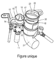
- a reducing agent reservoir filling chute 10 and a fuel tank chute 20 there is shown a reducing agent reservoir filling chute 10 and a fuel tank chute 20.
- the trough 10 extends towards the reducing agent reservoir via a filling line 11 while the trough 20 extends towards the fuel tank via a filling line 21.
- These two troughs are arranged side by side and may for example be accessible under a hatch which is common to them.
- the trough 10 of the reducing agent reservoir is provided with a plug 12 and the fuel filling trough 20 is provided with a plug 22.
- the plug 12 is here equipped with an impedance link 13 which, in a manner known per se, is a flexible link connecting the trough 10 to the plug 12.
- the link 13 here consists of an elastomeric plastic strip and two rings, one 14 surrounding the chute 10 and the other 15 surrounding the plug 12 so that when the plug 12 is disengaged from the chute 10 it is retained against an inadvertent fall by the link 13 which links it to the chute 10.
- the This fastening link 13 thus forms a loop or part of an arc extending from the ring 14 to the ring 15 on the side of the plug 12 so that the link 13 extends opposite the plug. 22 with respect to the reducing agent plug 12.
- the fastening link 13 is extended here in the direction of the plug 10 in the form of an extension 16 which extends under the plug 22.
- the extension 16 is extends from the reducing agent plug 12 substantially radially relative to the longitudinal direction of the trough 10.
- the extension 16 of the captive link and the plug comprises a tongue 17 and then an arcuate part 18 as fixing means which part is complementary to the circumference of the carburizing chute 20 and which is sandwiched between the cap 22 and the fuel filler neck 20 to retain the extension 16 of a reducing agent reservoir opening 12.
- the cap 22 thus comes to press the part in an arc 18 against a flange of the chute 20, thus preventing extraction of the arcuate portion 18 when the fuel cap 22 is closed.
- the arcuate portion 18 thus forms two branches configured to come on both sides of the fuel tank cap 22 and anchor therebelow.
- the tongue 17 and the arcuate part 18 thus form an extension of the plug 12 which indexes the position of the plug 12 on the position of the plug 22.
- the arcuate part 18 may be replaced by a ring surrounding the chute 20 as fastening means for cooperating with the fuel tank cap.
- the tongue 17 is made of flexible material but alternatively, the material constituting the tongue may have sufficient rigidity so that, even if the arcuate portion 18 is not sandwiched, its separation from the chute 20 is not possible without extracting the fuel cap 22. It is in particular possible to produce the tongue 17 in the form of a metal strip, optionally embedded in a plastic material, preferably in the plastic material forming by continuity the handle of the link of captivity 13. Similarly, alternatively the arcuate part 18 may be absent, the tongue 17 alone producing a locking plug 12 indexing the presence of the fuel cap 22 on its chute 20.
- the reducing agent plug 12 can be removed only if the fuel cap 22 is itself separated from its chute.
- the cap of fuel 22 having a lock 23 here only the vehicle owner can release the plug 12 of the chute 10 for filling the reducing agent.
- extension 16 integral with the link of captivity 13 alternatively such an extension can be replaced by any other form extending from the reducing agent plug 12 and coming to index on the position of the fuel cap 22.
- extension coming from the material with the reducing agent plug 12 and coming under the fuel cap 22 is possible to provide an extension coming from the material with the reducing agent plug 12 and coming under the fuel cap 22.
- Such an indexing extension 16 coming under the fuel cap 22 not only prevents or delays an intrusion, but more generally forms a tamper-evident tab making it possible to observe or, if necessary, prove an intrusion.
- Such a device avoids the adoption of an actuator door and the extra cost inherent in it.
- Such a device not only limits the risk of plug theft or reducing agent but also limits the risk of sabotage. Indeed it is no longer possible for a saboteur to put for example gasoline in the reducing agent tank, at least without the customer knowing by the finding that the tongue 17 has been damaged.
- Such a device thus compensates for the absence of a liquid analyzer in the reducing agent reservoir, thus making it possible to avoid immobilizations, engine runaways and fire risks, especially if a fuel injection occurs in a vehicle. particulate filter being regenerated.
Landscapes
- Engineering & Computer Science (AREA)
- Chemical & Material Sciences (AREA)
- Combustion & Propulsion (AREA)
- Transportation (AREA)
- Mechanical Engineering (AREA)
- Life Sciences & Earth Sciences (AREA)
- Sustainable Development (AREA)
- Sustainable Energy (AREA)
- Cooling, Air Intake And Gas Exhaust, And Fuel Tank Arrangements In Propulsion Units (AREA)
Abstract
Description
- L'invention concerne les bouchons de réservoirs de véhicules automobiles et notamment les bouchons de réservoirs d'agent réducteur d'oxyde d'azote.
- De plus en plus de véhicules automobiles vont être équipés d'un système de réduction catalytique sélective des oxydes d'azote ou SCR pour Selective Catalytic Reduction en Anglais. De tels véhicules sont équipés d'un réservoir d'agent réducteur d'oxyde d'azote tel que de l'urée, lequel agent réducteur est typiquement décomposé en ammoniac au sein du véhicule. Un tel agent réducteur d'oxyde d'azote est notamment connu sous le nom commercial de Adblue, marque déposée.
- Comme pour les bouchons de réservoir de carburant, il existe un besoin d'empêcher l'accès au réservoir à une personne non autorisée. Pour le réservoir de carburant, on connait le principe du bouchon ayant un verrou intégré ou de la trappe équipée d'un verrou commandé lequel se libère simultanément au déverrouillage des portes du véhicule.
- Le bouchon de réservoir d'agent réducteur est souvent placé à proximité du bouchon de carburant, et peut ainsi être enfermé par la même trappe que le bouchon de carburant. Il reste néanmoins un besoin pour un verrouillage du bouchon d'agent réducteur en l'absence de trappe commandée. Il existe en outre un besoin pour un bouchon d'agent réducteur qui participe à empêcher une confusion entre les deux bouchons au moment du remplissage.
- Le but de l'invention est de répondre à ces besoins.
- Ce but est atteint selon l'invention grâce à un dispositif d'obturation de réservoir d'agent réducteur d'oxydes d'azote de véhicule automobile, le dispositif comprenant une goulotte de réservoir d'agent réducteur et un bouchon de réservoir d'agent réducteur, caractérisé en ce qu'il comporte une extension s'étendant depuis le bouchon, laquelle extension comprend des moyens de fixation destinés à coopérer avec un bouchon de réservoir de carburant pour retenir l'extension à l'encontre d'une ouverture du bouchon de réservoir d'agent réducteur.
- Avantageusement, le dispositif comporte un lien d'imperdabilité du bouchon de réservoir d'agent réducteur, et l'extension est venue de matière avec le lien d'imperdabilité.
- Avantageusement, l'extension s'étend depuis le bouchon de réservoir d'agent réducteur radialement à la goulotte de réservoir d'agent réducteur.
- L'invention concerne également un dispositif d'obturation de réservoir d'agent réducteur et d'obturation de réservoir de carburant, le dispositif comprenant un tel dispositif d'obturation de réservoir d'agent réducteur et comprenant en outre une goulotte de réservoir de carburant et un bouchon de réservoir de carburant
- Avantageusement, les moyens de fixation de l'extension comportent deux branches configurées pour venir de part et d'autre de la goulotte de réservoir de carburant.
- Avantageusement, les moyens de fixation de l'extension sont pincés entre le bouchon du réservoir de carburant et la goulotte du réservoir de carburant pour retenir l'extension à l'encontre d'une ouverture du bouchon de réservoir d'agent réducteur.
- Avantageusement, l'extension comporte une pièce métallique s'étendant entre les deux bouchons.
- Avantageusement, la pièce métallique est noyée dans un matériau plastique lequel matériau plastique est venu de matière avec un matériau plastique constitutif du lien d'imperdabilité.
- Avantageusement, l'extension est rigide de telle sorte que le bouchon du réservoir d'agent réducteur ne peut pas être ouvert sans ouvrir le bouchon du réservoir de carburant de manière à permettre à l'extension de s'écarter de la goulotte du réservoir de carburant.
- Avantageusement, l'extension forme un anneau disposé de manière à entourer la goulotte du réservoir de carburant.
- D'autres caractéristiques, buts et avantages de l'invention apparaîtront à la lecture de la description détaillée qui va suivre, faite en référence à la figure annexée qui représente un bouchon de réservoir d'agent réducteur selon un mode de réalisation de l'invention.
- Sur la figure annexée, on a représenté une goulotte 10 de remplissage de réservoir d'agent réducteur et une goulotte 20 de réservoir de carburant. La goulotte 10 se prolonge vers le réservoir d'agent réducteur par une conduite de remplissage 11 tandis que la goulotte 20 se prolonge vers le réservoir de carburant par une conduite de remplissage 21. Ces deux goulottes sont disposées côte à côte et peuvent par exemple être accessibles sous une trappe qui leur est commune. La goulotte 10 du réservoir d'agent réducteur est munie d'un bouchon 12 et la goulotte de remplissage de carburant 20 est munie d'un bouchon 22.
- Le bouchon 12 est ici équipé d'un lien d'imperdabilitié 13 qui, de manière connue en soi, est un lien souple reliant la goulotte 10 au bouchon 12. Le lien 13 est ici constitué d'une bande en matière plastique élastomère et de deux anneaux, l'un 14 entourant la goulotte 10 et l'autre 15 entourant le bouchon 12 de telle sorte que lorsque le bouchon 12 est désolidarisé de la goulotte 10 il est retenu à l'encontre d'une chute intempestive par le lien 13 qui le lie à la goulotte 10. Le lien d'imperdabilité 13 forme ainsi une anse ou partie en arc de cercle s'étendant de l'anneau 14 à l'anneau 15 sur le côté du bouchon 12 de telle sorte que le lien 13 s'étend à l'opposé du bouchon de carburant 22 par rapport au bouchon d'agent réducteur 12. Le lien d'imperdabilité 13 se prolonge ici en direction du bouchon 10 sous la forme d'une extension 16 laquelle s'étend sous le bouchon 22. L'extension 16 s'étend depuis le bouchon d'agent réducteur 12 sensiblement radialement relativement au sens longitudinal de goulotte 10. L'extension 16 du lien d'imperdabilité et du bouchon comprend une languette 17 puis une partie en arc de cercle 18 comme moyens de fixation laquelle partie est complémentaire de la circonférence de la goulotte de carburant 20 et laquelle est prise en sandwich entre le bouchon 22 et la goulotte 20 de remplissage de carburant pour retenir l'extension 16 d'une ouverture de réservoir d'agent réducteur 12. Le bouchon 22 vient donc plaquer la partie en arc de cercle 18 contre une collerette de la goulotte 20, empêchant ainsi une extraction de la partie en arc de cercle 18 lorsque le bouchon de carburant 22 est fermé. La partie en arc de cercle 18 forme donc deux branches configurées pour venir de part et d'autre du bouchon de réservoir de carburant 22 et s'ancrer sous celui-ci. La languette 17 et la partie en arc de cercle 18 forment ainsi une extension du bouchon 12 venant indexer la position du bouchon 12 sur la position du bouchon 22.
- La partie en arc de cercle 18 peut être remplacée par un anneau entourant la goulotte 20 comme moyens de fixation destinés à coopérer avec le bouchon de réservoir de carburant. Dans le présent mode de réalisation, la languette 17 est réalisée en matériau souple mais en variante, le matériau constitutif de la languette peut présenter une rigidité suffisante pour que, même si la partie en arc de cercle 18 n'est pas prise en sandwich, sa séparation de la goulotte 20 n'est pas possible sans extraction du bouchon de carburant 22. Il est notamment possible de réaliser la languette 17 sous la forme d'une bande métallique, éventuellement noyée dans une matière plastique, préférentiellement dans la matière plastique formant par continuité l'anse du lien d'imperdabilité 13. De même, en variante la partie en arc de cercle 18 peut être absente, la languette 17 seule produisant un verrouillage du bouchon 12 en indexation de la présence du bouchon de carburant 22 sur sa goulotte 20.
- Grace à un tel dispositif, le bouchon d'agent réducteur 12 ne peut être retiré que si le bouchon de carburant 22 est lui-même séparé de sa goulotte. Le bouchon de carburant 22 présentant ici un verrou 23, seul le propriétaire du véhicule peut donc libérer le bouchon 12 de la goulotte 10 de remplissage de l'agent réducteur.
- Bien que l'on ait décrit ici une extension 16 faisant corps avec le lien d'imperdabilité 13, en variante une telle extension peut être remplacée par toute autre forme s'étendant depuis le bouchon d'agent réducteur 12 et venant s'indexer sur la position du bouchon de carburant 22. Ainsi on peut prévoir une extension venant de matière avec le bouchon d'agent réducteur 12 et venant se placer sous le bouchon de carburant 22.
- Une telle extension d'indexation 16 venant se placer sous le bouchon de carburant 22 permet non seulement d'empêcher ou de retarder une intrusion, mais forme plus généralement une languette d'inviolabilité permettant de constater ou au besoin de prouver une intrusion. Un tel dispositif permet d'éviter l'adoption d'une trappe à actionneur et le surcout inhérent à celle-ci. Un tel dispositif limite non seulement le risque de vol de bouchon ou d'agent réducteur mais limite aussi le risque de sabotage. En effet il n'est plus possible à un saboteur de mettre par exemple de l'essence dans le réservoir d'agent réducteur, à tout le moins sans que le client le sache par la constatation que la languette 17 a été endommagée. Un tel dispositif pallie donc à l'absence d'analyseur de liquide dans le réservoir d'agent réducteur, permettant ainsi d'éviter des immobilisations, des emballements moteur et des risques d'incendie notamment si il se produit une injection de carburant dans un filtre à particules en cours de régénération.
Claims (10)
- Dispositif d'obturation de réservoir d'agent réducteur d'oxydes d'azote de véhicule automobile, le dispositif comprenant une goulotte de réservoir d'agent réducteur (10) et un bouchon (12) de réservoir d'agent réducteur, caractérisé en ce qu'il comporte une extension (16, 17, 18) s'étendant depuis le bouchon (12) laquelle extension (16, 17, 18) comprend des moyens de fixation destinés à coopérer avec un bouchon de réservoir de carburant (22) pour retenir l'extension (16,17,18) à l'encontre d'une ouverture du bouchon de réservoir d'agent réducteur (12).
- Dispositif d'obturation selon la revendication 1, caractérisé en ce qu'il comporte un lien d'imperdabilité (13, 14, 15) du bouchon de réservoir d'agent réducteur (12), et l'extension (16, 17, 18) est venue de matière avec le lien d'imperdabilité (13, 14, 15).
- Dispositif selon la revendication 1 ou la revendication 2, caractérisé en ce que l'extension (16, 17, 18) s'étend depuis le bouchon (12) de réservoir d'agent réducteur radialement à la goulotte (10) de réservoir d'agent réducteur.
- Dispositif d'obturation de réservoir d'agent réducteur et d'obturation de réservoir de carburant, le dispositif comprenant un dispositif d'obturation de réservoir d'agent réducteur selon l'une quelconque des revendications 1 à 3 et comprenant en outre une goulotte de réservoir de carburant (20) et un bouchon (22) de réservoir de carburant.
- Dispositif selon la revendication 4, caractérisé en ce que les moyens de fixation de l'extension (16, 17, 18) comportent deux branches configurées pour venir de part et d'autre de la goulotte (20) de réservoir de carburant.
- Dispositif selon la revendication 4 ou la revendication 5, caractérisé en ce que les moyens de fixation de l'extension (16, 17, 18) sont pincés entre le bouchon (22) du réservoir de carburant et la goulotte (20) du réservoir de carburant pour retenir l'extension (16, 17, 18) à l'encontre d'une ouverture du bouchon de réservoir d'agent réducteur (12).
- Dispositif selon l'une quelconque des revendications 4 à 6, caractérisé en ce que l'extension (16, 17, 18) comporte une pièce métallique s'étendant entre les deux bouchons (12, 22).
- Dispositif selon la revendication précédente, caractérisé en ce que la pièce métallique est noyée dans un matériau plastique lequel matériau plastique est venu de matière avec un matériau plastique constitutif du lien d'imperdabilité (16, 17, 18).
- Dispositif selon l'une quelconque des revendications 4 à 8, caractérisé en ce que l'extension (16, 17, 18) est rigide de telle sorte que le bouchon du réservoir d'agent réducteur (12) ne peut pas être ouvert sans ouvrir le bouchon du réservoir de carburant (22) de manière à permettre à l'extension (16, 17, 18) de s'écarter de la goulotte (20) du réservoir de carburant.
- Dispositif selon l'une quelconque des revendications 4 à 9, caractérisé en ce que l'extension (16, 17, 18) forme un anneau disposé de manière à entourer la goulotte (20) du réservoir de carburant.
Applications Claiming Priority (1)
| Application Number | Priority Date | Filing Date | Title |
|---|---|---|---|
| FR1550087A FR3031327B1 (fr) | 2015-01-07 | 2015-01-07 | Dispositif d’inviolabilite de reservoir d’agent reducteur de vehicule automobile |
Publications (1)
| Publication Number | Publication Date |
|---|---|
| EP3042797A1 true EP3042797A1 (fr) | 2016-07-13 |
Family
ID=52684540
Family Applications (1)
| Application Number | Title | Priority Date | Filing Date |
|---|---|---|---|
| EP15198461.4A Withdrawn EP3042797A1 (fr) | 2015-01-07 | 2015-12-08 | Dispositif d'inviolabilite de reservoir d'agent reducteur de vehicule automobile |
Country Status (2)
| Country | Link |
|---|---|
| EP (1) | EP3042797A1 (fr) |
| FR (1) | FR3031327B1 (fr) |
Cited By (2)
| Publication number | Priority date | Publication date | Assignee | Title |
|---|---|---|---|---|
| WO2018185229A1 (fr) * | 2017-04-06 | 2018-10-11 | Plastic Omnium Advanced Innovation And Research | Dispositif de protection temporaire destiné à être utilisé dans un véhivule à moteur |
| WO2018189439A1 (fr) * | 2017-04-13 | 2018-10-18 | Psa Automobiles Sa | Ensemble de deux reservoirs de fluide avec goulottes solidarisees |
Citations (3)
| Publication number | Priority date | Publication date | Assignee | Title |
|---|---|---|---|---|
| US5150808A (en) * | 1990-10-24 | 1992-09-29 | Tyrone Hamilton | Cap holder device |
| JPH10211821A (ja) * | 1996-11-27 | 1998-08-11 | Calsonic Corp | 紐付きキャップ |
| US20090145903A1 (en) * | 2007-12-11 | 2009-06-11 | Soltis Michael W | Fluid fill system for an automotive vehicle |
-
2015
- 2015-01-07 FR FR1550087A patent/FR3031327B1/fr not_active Expired - Fee Related
- 2015-12-08 EP EP15198461.4A patent/EP3042797A1/fr not_active Withdrawn
Patent Citations (3)
| Publication number | Priority date | Publication date | Assignee | Title |
|---|---|---|---|---|
| US5150808A (en) * | 1990-10-24 | 1992-09-29 | Tyrone Hamilton | Cap holder device |
| JPH10211821A (ja) * | 1996-11-27 | 1998-08-11 | Calsonic Corp | 紐付きキャップ |
| US20090145903A1 (en) * | 2007-12-11 | 2009-06-11 | Soltis Michael W | Fluid fill system for an automotive vehicle |
Cited By (3)
| Publication number | Priority date | Publication date | Assignee | Title |
|---|---|---|---|---|
| WO2018185229A1 (fr) * | 2017-04-06 | 2018-10-11 | Plastic Omnium Advanced Innovation And Research | Dispositif de protection temporaire destiné à être utilisé dans un véhivule à moteur |
| WO2018189439A1 (fr) * | 2017-04-13 | 2018-10-18 | Psa Automobiles Sa | Ensemble de deux reservoirs de fluide avec goulottes solidarisees |
| FR3065187A1 (fr) * | 2017-04-13 | 2018-10-19 | Peugeot Citroen Automobiles Sa | Ensemble de deux reservoirs de fluide avec goulottes solidarisees |
Also Published As
| Publication number | Publication date |
|---|---|
| FR3031327A1 (fr) | 2016-07-08 |
| FR3031327B1 (fr) | 2017-07-14 |
Similar Documents
| Publication | Publication Date | Title |
|---|---|---|
| EP2300331A2 (fr) | Bouchon clipse a onglet saillant pour un col de recipient | |
| FR3031327A1 (fr) | Dispositif d’inviolabilite de reservoir d’agent reducteur de vehicule automobile | |
| WO2015158553A2 (fr) | Ensemble de filtrage de fluide avec verouillage/deverouillage du corps de filtre | |
| FR2918841A1 (fr) | Bague d'identification pour animaux | |
| FR2967403A1 (fr) | Capsule de securite et de garantie d'inviolabilite et procede pour la mise en place de cette capsule, notamment sur une bouteille de gaz | |
| EP1610086B1 (fr) | Conteneur pour munition | |
| FR2714991A1 (fr) | Dispositifs de scellés et parties mâles de tels dispositifs. | |
| WO2020104908A2 (fr) | Conteneur équipé d'un système de verrouillage de conteneur | |
| FR3099809A1 (fr) | Dispositif de raccordement entre un élément tubulaire et une embase | |
| WO2010144966A1 (fr) | Ensemble capuchon de récipient de carburant | |
| EP3213804B1 (fr) | Dispositif de support pour filtre a gasoil d'un vehicule automobile | |
| US20150114960A1 (en) | Dust cover for capless fuel filler system | |
| EP2928767A1 (fr) | Engin sous marin équipé d'un système de remorquage | |
| FR3076798A1 (fr) | Carénage pour véhicule | |
| EP4204119B1 (fr) | Systeme de filtre a carburant a goupille de securite | |
| EP2923863B1 (fr) | Dispositif antivol pour attelage | |
| FR2917794A1 (fr) | Dispositif de fixation inviolable d'une piece dans une decoupe prevue sur une structure. | |
| FR2979063A1 (fr) | Filtre a liquide, notamment filtre a huile | |
| CN1951779A (zh) | 显窃启密封组件 | |
| IES85620Y1 (en) | A security cap and a locking device for a cap | |
| FR3134142A1 (fr) | Dispositif anti-violation pour bouchon de réservoir de dégazage | |
| GB2467427A (en) | Security Cap for Tank Neck having Retaining Pin | |
| FR2982537A1 (fr) | Dispositif de remplissage d'un reservoir d'un vehicule automobile | |
| WO2005073102A1 (fr) | Dispositif de securisation de tubes | |
| EP2912357B1 (fr) | Vanne a usage unique |
Legal Events
| Date | Code | Title | Description |
|---|---|---|---|
| PUAI | Public reference made under article 153(3) epc to a published international application that has entered the european phase |
Free format text: ORIGINAL CODE: 0009012 |
|
| AK | Designated contracting states |
Kind code of ref document: A1 Designated state(s): AL AT BE BG CH CY CZ DE DK EE ES FI FR GB GR HR HU IE IS IT LI LT LU LV MC MK MT NL NO PL PT RO RS SE SI SK SM TR |
|
| AX | Request for extension of the european patent |
Extension state: BA ME |
|
| 17P | Request for examination filed |
Effective date: 20161208 |
|
| RBV | Designated contracting states (corrected) |
Designated state(s): AL AT BE BG CH CY CZ DE DK EE ES FI FR GB GR HR HU IE IS IT LI LT LU LV MC MK MT NL NO PL PT RO RS SE SI SK SM TR |
|
| GRAP | Despatch of communication of intention to grant a patent |
Free format text: ORIGINAL CODE: EPIDOSNIGR1 |
|
| INTG | Intention to grant announced |
Effective date: 20170622 |
|
| RAP1 | Party data changed (applicant data changed or rights of an application transferred) |
Owner name: PSA AUTOMOBILES SA |
|
| STAA | Information on the status of an ep patent application or granted ep patent |
Free format text: STATUS: THE APPLICATION IS DEEMED TO BE WITHDRAWN |
|
| 18D | Application deemed to be withdrawn |
Effective date: 20171103 |