EP3042706B1 - Composite defoaming method for high-viscosity pure-chitosan spinning solution - Google Patents
Composite defoaming method for high-viscosity pure-chitosan spinning solution Download PDFInfo
- Publication number
- EP3042706B1 EP3042706B1 EP14841045.9A EP14841045A EP3042706B1 EP 3042706 B1 EP3042706 B1 EP 3042706B1 EP 14841045 A EP14841045 A EP 14841045A EP 3042706 B1 EP3042706 B1 EP 3042706B1
- Authority
- EP
- European Patent Office
- Prior art keywords
- spinning solution
- degassing
- umbrella
- vessel
- diffusion plate
- Prior art date
- Legal status (The legal status is an assumption and is not a legal conclusion. Google has not performed a legal analysis and makes no representation as to the accuracy of the status listed.)
- Active
Links
Images

Classifications
-
- B—PERFORMING OPERATIONS; TRANSPORTING
- B01—PHYSICAL OR CHEMICAL PROCESSES OR APPARATUS IN GENERAL
- B01D—SEPARATION
- B01D19/00—Degasification of liquids
- B01D19/02—Foam dispersion or prevention
-
- B—PERFORMING OPERATIONS; TRANSPORTING
- B01—PHYSICAL OR CHEMICAL PROCESSES OR APPARATUS IN GENERAL
- B01D—SEPARATION
- B01D19/00—Degasification of liquids
-
- B—PERFORMING OPERATIONS; TRANSPORTING
- B01—PHYSICAL OR CHEMICAL PROCESSES OR APPARATUS IN GENERAL
- B01F—MIXING, e.g. DISSOLVING, EMULSIFYING OR DISPERSING
- B01F27/00—Mixers with rotary stirring devices in fixed receptacles; Kneaders
- B01F27/80—Mixers with rotary stirring devices in fixed receptacles; Kneaders with stirrers rotating about a substantially vertical axis
- B01F27/91—Mixers with rotary stirring devices in fixed receptacles; Kneaders with stirrers rotating about a substantially vertical axis with propellers
-
- B—PERFORMING OPERATIONS; TRANSPORTING
- B29—WORKING OF PLASTICS; WORKING OF SUBSTANCES IN A PLASTIC STATE IN GENERAL
- B29B—PREPARATION OR PRETREATMENT OF THE MATERIAL TO BE SHAPED; MAKING GRANULES OR PREFORMS; RECOVERY OF PLASTICS OR OTHER CONSTITUENTS OF WASTE MATERIAL CONTAINING PLASTICS
- B29B7/00—Mixing; Kneading
- B29B7/02—Mixing; Kneading non-continuous, with mechanical mixing or kneading devices, i.e. batch type
- B29B7/06—Mixing; Kneading non-continuous, with mechanical mixing or kneading devices, i.e. batch type with movable mixing or kneading devices
- B29B7/10—Mixing; Kneading non-continuous, with mechanical mixing or kneading devices, i.e. batch type with movable mixing or kneading devices rotary
- B29B7/12—Mixing; Kneading non-continuous, with mechanical mixing or kneading devices, i.e. batch type with movable mixing or kneading devices rotary with single shaft
- B29B7/14—Mixing; Kneading non-continuous, with mechanical mixing or kneading devices, i.e. batch type with movable mixing or kneading devices rotary with single shaft with screw or helix
-
- B—PERFORMING OPERATIONS; TRANSPORTING
- B29—WORKING OF PLASTICS; WORKING OF SUBSTANCES IN A PLASTIC STATE IN GENERAL
- B29B—PREPARATION OR PRETREATMENT OF THE MATERIAL TO BE SHAPED; MAKING GRANULES OR PREFORMS; RECOVERY OF PLASTICS OR OTHER CONSTITUENTS OF WASTE MATERIAL CONTAINING PLASTICS
- B29B7/00—Mixing; Kneading
- B29B7/80—Component parts, details or accessories; Auxiliary operations
- B29B7/84—Venting or degassing ; Removing liquids, e.g. by evaporating components
- B29B7/845—Venting, degassing or removing evaporated components in devices with rotary stirrers
-
- B—PERFORMING OPERATIONS; TRANSPORTING
- B29—WORKING OF PLASTICS; WORKING OF SUBSTANCES IN A PLASTIC STATE IN GENERAL
- B29B—PREPARATION OR PRETREATMENT OF THE MATERIAL TO BE SHAPED; MAKING GRANULES OR PREFORMS; RECOVERY OF PLASTICS OR OTHER CONSTITUENTS OF WASTE MATERIAL CONTAINING PLASTICS
- B29B7/00—Mixing; Kneading
- B29B7/80—Component parts, details or accessories; Auxiliary operations
- B29B7/86—Component parts, details or accessories; Auxiliary operations for working at sub- or superatmospheric pressure
-
- D—TEXTILES; PAPER
- D01—NATURAL OR MAN-MADE THREADS OR FIBRES; SPINNING
- D01D—MECHANICAL METHODS OR APPARATUS IN THE MANUFACTURE OF ARTIFICIAL FILAMENTS, THREADS, FIBRES, BRISTLES OR RIBBONS
- D01D1/00—Treatment of filament-forming or like material
- D01D1/06—Feeding liquid to the spinning head
- D01D1/065—Addition and mixing of substances to the spinning solution or to the melt; Homogenising
-
- D—TEXTILES; PAPER
- D01—NATURAL OR MAN-MADE THREADS OR FIBRES; SPINNING
- D01D—MECHANICAL METHODS OR APPARATUS IN THE MANUFACTURE OF ARTIFICIAL FILAMENTS, THREADS, FIBRES, BRISTLES OR RIBBONS
- D01D1/00—Treatment of filament-forming or like material
- D01D1/10—Filtering or de-aerating the spinning solution or melt
- D01D1/103—De-aerating
-
- D—TEXTILES; PAPER
- D01—NATURAL OR MAN-MADE THREADS OR FIBRES; SPINNING
- D01F—CHEMICAL FEATURES IN THE MANUFACTURE OF ARTIFICIAL FILAMENTS, THREADS, FIBRES, BRISTLES OR RIBBONS; APPARATUS SPECIALLY ADAPTED FOR THE MANUFACTURE OF CARBON FILAMENTS
- D01F9/00—Artificial filaments or the like of other substances; Manufacture thereof; Apparatus specially adapted for the manufacture of carbon filaments
-
- Y—GENERAL TAGGING OF NEW TECHNOLOGICAL DEVELOPMENTS; GENERAL TAGGING OF CROSS-SECTIONAL TECHNOLOGIES SPANNING OVER SEVERAL SECTIONS OF THE IPC; TECHNICAL SUBJECTS COVERED BY FORMER USPC CROSS-REFERENCE ART COLLECTIONS [XRACs] AND DIGESTS
- Y02—TECHNOLOGIES OR APPLICATIONS FOR MITIGATION OR ADAPTATION AGAINST CLIMATE CHANGE
- Y02P—CLIMATE CHANGE MITIGATION TECHNOLOGIES IN THE PRODUCTION OR PROCESSING OF GOODS
- Y02P70/00—Climate change mitigation technologies in the production process for final industrial or consumer products
- Y02P70/50—Manufacturing or production processes characterised by the final manufactured product
- Y02P70/62—Manufacturing or production processes characterised by the final manufactured product related technologies for production or treatment of textile or flexible materials or products thereof, including footwear
Definitions
- the present invention relates to a degassing method for ultra-high-viscosity spinning solutions, in particular to a degassing method for ultra-high-viscosity pure-chitosan spinning solutions.
- Pure chitosan fibers refer to the fibers made of extracts from shells of shrimps and crabs, and have many advantages as compared with the conventional land natural fibers and synthetic fibers.
- pure chitosan fibers neither depend on petroleum nor compete against crops for the land, and serve as the third source of chemical fibers.
- the waste reutilization conforms to the trend of environmentally sustainable development.
- pure chitosan fibers have broad-spectrum antimicrobial activity, mildew resistance, excellent biocompatibility and no immunogenicity, and also have the effects of adsorption chelation, hemostasis, wound-healing and scar formation inhibition. Owing to these functions, pure chitosan fibers can be widely applied in the fields of aerospace, medical and health care, military and civil textiles and filter protection, have a good market prospect, and play a positive role in promoting human health.
- high-viscocity pure chitosan spinning solution can meet the requirements for spinning of high-quality pure chitosan fibers, and the desired viscocity of spinning solution for spinning of high-quality pure chitosan fibers is greater than 450,000 mpa ⁇ s.
- flake chitosan Upon decalcification and deproteinization, a great deal of cavities are generated in the structure of flake chitosan, and these cavities are filled with air, flake chitosan itself is formed by lamination of two or more layers, with a great deal of air in the gaps.
- the air in the cavities and gaps are entrained in the chitosan solution and can not escape.
- a large amount of air bubbles are generated during stir-dissolution, filtration and transport of the chitosan spinning solution, and these air bubbles enter the degassing vessel along with the spinning solution.
- the spinning solution should be degassed before being sprayed into the solidification bath from the spinning plate, if there are air bubbles in the spinning solution in the solidification bath, the air bubbles escape to cause filament breakage, and the viscocity of the pure chitosan spinning solution is greater than 450,000 mpa ⁇ s, which is almost 10 times the viscocity of the common spinning solution, as a result, the conventional degassing process has an extremely-low production efficiency and fails to realize industrial production.
- the present invention solves the technical problems in the prior art, and provides a degassing method with high degassing efficiency and good degassing effect, and is applicable to spinning solutions of a wide range of viscocity.
- Degassing of chitosan is e.g. disclosed in CN102851790 where the chitosan solution is exposed to a vacuum.
- An apparatus to perform degassing in a tank that feeds a solution onto an umbrella shaped cone so that the solution is flowing as a film onto it and whereby this is repeated by recirculating the solution via an internal central tube with a helical screw inside is disclosed in GB2079616 .
- the present invention adopts the technical scheme as follows:
- the degassing vessel comprises a degassing vessel body (1) and a stirring device (2).
- a feed port (3), a vacuum port (5), a vacuum relief port and a vacuum meter are disposed at the upper part of the degassing vessel body (1);
- a discharge port (4) is disposed at the bottom center, and a sampling port (18) is disposed on the bottom lateral side;
- an annular feed pipe (7) is fixedly disposed at the inner upper part of the degassing vessel body (1), and the annular feed pipe (7) communicates with the feed port (3); and small discharge holes (8) of 0.5-5 mm diameter are distributed on the part below the horizontal central plane of the annular feed pipe (7).
- An inner cylinder body (9) is fixedly disposed in the axial position inside the degassing vessel body (1), the upper end opening of the inner cylinder body (9) is closed by a round plate on which small liquid outlet holes (11) of 0.5-5 mm diameter are distributed and the lower end opening is open; an umbrella-shaped diffusion plate (10) is fixedly disposed at the periphery of the upper half part of the inner cylinder body (9), the inner cylinder body (9) is divided by the umbrella-shaped diffusion plate (10) to upper and lower portions; a gap of 100-200 mm is formed between the outer edge of the umbrella-shaped diffusion plate (10) and the inner wall of the degassing vessel body (1); and small liquid outlet holes (11) of 0.5-5 mm diameter are distributed on the body of the inner cylinder body (9) above the umbrella-shaped diffusion plate (10).
- a stirring power device (13) comprises a motor, a speed reducer and a power support, the power support is disposed in the center position of the outer top wall of the degassing vessel (1), and the speed reducer and the motor are disposed on the power support; the upper end of a stirring shaft (12) is disposed on the stirring power device (13) such that the stirring shaft (12) and the output shaft of the speed reducer are engaged; the stirring shaft (12), from top to bottom, passes through a seat-mounted bearing which is disposed inside the power support, passes through a mechanical seal device (16) used for sealing the assembly gap between the degassing vessel (1) and the stirring shaft (12), enters the degassing vessel (1) with the lower end being fixed on the seat-mounted bearing (6); and by the fixation of the upper and lower ends, the stirring shaft (12) run more stably.
- a gap of 3 mm-5 mm is formed between the inner wall of the inner cylinder body (9) and the screw propeller (14).
- step (2) the spinning solution is delivered to the feed port of the degassing vessel from the dissolution vessel upon the filtration of a two-stage filter, under compressed air of 0.8 MPa-1.2 MPa as power.
- step (3) the stirring shaft with the screw propeller lifts the spinning solution up to the umbrella-shaped diffusion plate from the bottom of the degassing vessel, with the rotational speed of 60-90 rpm.
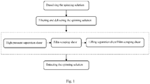
- Fig.1 is a flow diagram of the present invention
- Fig. 1 is a structural schematic diagram of the present invention
- the pure-chitosan spinning solution uniformly drops onto the umbrella-shaped diffusion plate, under the action of gravity and the action of inclination of the umbrella-shaped diffusion plate, the spinning solution flows from the inner edge to the outer edge of the umbrella-shaped diffusion plate to form a spinning solution film which increases the degassing area, and under the condition that the inner pressure of the degassing vessel is 500 Pa, a part of air bubbles escape;
- the spinning solution flows to the outer edge of the umbrella-shaped diffusion plate, the spinning solution falls freely under the gravity action and drops to the bottom of the degassing vessel, during down-flow, the outer edge of the umbrella-shaped diffusion plate takes the shear action on the spinning solution, leading to the changes of the interfacial layer of the spinning solution, as a result, the air bubbles escape rapidly, thereby completing the second-stage degassing process by film-scraping shear.
- the pure-chitosan spinning solution is stirred by the screw propeller, lifted up to the inner cavity of the inner cylinder body at the upper part of the umbrella-shaped diffusion plate, under the stirring action of the stirring shaft with the screw propeller at the constant rotational speed of 90 rpm, as the inner body wall of the upper part of the umbrella-shaped diffusion plate and the upper cylinder opening are distributed with the small liquid outlet holes, the spinning solution is forced to flow out of the small liquid outlet holes, thereby achieving the effect of degassing process (a); when the spinning solution drops to the vessel bottom from the umbrella-shaped diffusion plate, the effect of degassing process (b) is achieved, as a result, the effects of both degassing process (a) and degassing process (b) are achieved in one step by the stirring-lifting device alone.
- the problem in the prior art that the spinning solution at the bottom of the degassing vessel is not degassed can be solved.
- the device runs continuously and completed the high-efficiency high-quality
- step (3) is repeated until the detection result is eligible.
- Example 1 The steps of Example 1 are re-performed, under the conditions that the 6 tons of ultra-pure-chitosan spinning solution having 450,000 mpa ⁇ s viscosity which is thoroughly dissolved in the dissolution vessel is used, compressed air of 1.2 MPa is used as power, the degassing vessel is vacuumized and the inner pressure of the degassing vessel is maintained to be 3,000 Pa, and the stirring shaft runs with the constant rotational speed of 60 rpm, thereby completing high-efficiency high-quality degassing operation of the present invention.
- Example 1 The steps of Example 1 are re-performed, under the conditions that the 6 tons of ultra-pure-chitosan spinning solution having 480,000 mpa ⁇ s viscosity which is thoroughly dissolved in the dissolution vessel is used, compressed air of 1.0 MPa is used as power, the degassing vessel is vacuumized and the inner pressure of the degassing vessel is maintained to be 2,000 Pa, and the stirring shaft runs with the constant rotational speed of 70 rpm, thereby completing high-efficiency high-quality degassing operation of the present invention.
- the degassing efficiency of pure-chitosan spinning solution is increased, which can not only achieve continuous industrial production but also avoid the reduction in viscocity of the spinning solution, thereby ensuring the quality of pure-chitosan fibers.
- the present invention is also applicable to the degassing operation of other high-viscocity spinning solutions.
Landscapes
- Engineering & Computer Science (AREA)
- Chemical & Material Sciences (AREA)
- Chemical Kinetics & Catalysis (AREA)
- Textile Engineering (AREA)
- Mechanical Engineering (AREA)
- Dispersion Chemistry (AREA)
- General Chemical & Material Sciences (AREA)
- Degasification And Air Bubble Elimination (AREA)
- Artificial Filaments (AREA)
- Spinning Methods And Devices For Manufacturing Artificial Fibers (AREA)
- Polysaccharides And Polysaccharide Derivatives (AREA)
Description
- The present invention relates to a degassing method for ultra-high-viscosity spinning solutions, in particular to a degassing method for ultra-high-viscosity pure-chitosan spinning solutions.
- Pure chitosan fibers refer to the fibers made of extracts from shells of shrimps and crabs, and have many advantages as compared with the conventional land natural fibers and synthetic fibers. On the one hand, pure chitosan fibers neither depend on petroleum nor compete against crops for the land, and serve as the third source of chemical fibers. On the other hand, the waste reutilization conforms to the trend of environmentally sustainable development. Furthermore, pure chitosan fibers have broad-spectrum antimicrobial activity, mildew resistance, excellent biocompatibility and no immunogenicity, and also have the effects of adsorption chelation, hemostasis, wound-healing and scar formation inhibition. Owing to these functions, pure chitosan fibers can be widely applied in the fields of aerospace, medical and health care, military and civil textiles and filter protection, have a good market prospect, and play a positive role in promoting human health.
- Deacetylation and viscocity are two important quality indicators of chitosan. It is well known that the greater the molecular weight of chitosan, the higher the viscocity. The relation (Mark-Houwink) between viscocity and molecular weight is represented by the formula: [η] = kMα (η: viscocity, mpa·s, K: constant, M: relative molecular mass, α: a numerical value related to molecular weight). It thus can be seen that the higher the viscocity of pure chitosan spinning solution, the greater the molecular weight, so that the pure chitosan fibers spun therefrom are better in dry-breaking strength, breaking elongation and spinnability. Accordingly, only high-viscocity pure chitosan spinning solution can meet the requirements for spinning of high-quality pure chitosan fibers, and the desired viscocity of spinning solution for spinning of high-quality pure chitosan fibers is greater than 450,000 mpa·s.
- Upon decalcification and deproteinization, a great deal of cavities are generated in the structure of flake chitosan, and these cavities are filled with air, flake chitosan itself is formed by lamination of two or more layers, with a great deal of air in the gaps. During the dissolution of chitosan, the air in the cavities and gaps are entrained in the chitosan solution and can not escape. In addition, a large amount of air bubbles are generated during stir-dissolution, filtration and transport of the chitosan spinning solution, and these air bubbles enter the degassing vessel along with the spinning solution.
- In the wet-spinning process, the spinning solution should be degassed before being sprayed into the solidification bath from the spinning plate, if there are air bubbles in the spinning solution in the solidification bath, the air bubbles escape to cause filament breakage, and the viscocity of the pure chitosan spinning solution is greater than 450,000 mpa·s, which is almost 10 times the viscocity of the common spinning solution, as a result, the conventional degassing process has an extremely-low production efficiency and fails to realize industrial production.
- The present invention solves the technical problems in the prior art, and provides a degassing method with high degassing efficiency and good degassing effect, and is applicable to spinning solutions of a wide range of viscocity. Degassing of chitosan is e.g. disclosed in
CN102851790 where the chitosan solution is exposed to a vacuum. An apparatus to perform degassing in a tank that feeds a solution onto an umbrella shaped cone so that the solution is flowing as a film onto it and whereby this is repeated by recirculating the solution via an internal central tube with a helical screw inside is disclosed inGB2079616 - The present invention adopts the technical scheme as follows:
- a combined degassing method for a high-viscosity pure-chitosan spinning solution is characterized by comprising the following steps of:
- step 1, thoroughly dissolving the spinning solution in a dissolution vessel for subsequent use, the viscosity thereof reaching 450,000-500,000 mpa·s;
-
step 2, delivering the spinning solution in step 1 to the feed port of a degassing vessel from the dissolution vessel through a filter under the action of compressed air as power; - step 3, in the degassing vessel, under the conditions of vacuumizing and maintaining the inner pressure of the degassing vessel to be 500-3,000 Pa, performing continuous treatment on the spinning solution in
step 2 by a combined degassing process integrating separation, film-scraping, lifting and shear, specifically comprising:- (a) high-pressure separation shear: forcing the spinning solution in
step 2 which is delivered to the feed port of the degassing vessel under the power of compress air to pass through small discharge holes distributed at the bottom of an annular feed pipe; - (b) film-scraping shear: enabling the spinning solution from step (a) to drop onto an umbrella-shaped diffusion plate in the degassing vessel, flow from the inner edge to the outer edge of the umbrella-shaped diffusion plate, and drop to the bottom of the degassing vessel when flowing to the outer edge of the umbrella-shaped diffusion plate;
- (c) lifting separation shear and film-scraping shear: lifting the spinning solution at the bottom of the degassing vessel in step (b) up to the inner cavity of an inner cylinder body which is located above the umbrella-shaped diffusion plate via a stirring shaft with a screw propeller, enabling the solution to drop onto the umbrella-shaped diffusion plate through small liquid outlet holes and then drop to the bottom of the degassing vessel from the umbrella-shaped diffusion plate;
- (a) high-pressure separation shear: forcing the spinning solution in
- repeating step (c);
- steps (a), (b) and (c) being completed in the degassing vessel;
- step 4, sampling the spinning solution in step (3) at a sampling port for the detection of degassing degree, finishing the degassing operation if the detection result is eligible, otherwise repeating step (3) until the detection result is eligible.
- The degassing vessel comprises a degassing vessel body (1) and a stirring device (2). A feed port (3), a vacuum port (5), a vacuum relief port and a vacuum meter are disposed at the upper part of the degassing vessel body (1); a discharge port (4) is disposed at the bottom center, and a sampling port (18) is disposed on the bottom lateral side; an annular feed pipe (7) is fixedly disposed at the inner upper part of the degassing vessel body (1), and the annular feed pipe (7) communicates with the feed port (3); and small discharge holes (8) of 0.5-5 mm diameter are distributed on the part below the horizontal central plane of the annular feed pipe (7).
- An inner cylinder body (9) is fixedly disposed in the axial position inside the degassing vessel body (1), the upper end opening of the inner cylinder body (9) is closed by a round plate on which small liquid outlet holes (11) of 0.5-5 mm diameter are distributed and the lower end opening is open; an umbrella-shaped diffusion plate (10) is fixedly disposed at the periphery of the upper half part of the inner cylinder body (9), the inner cylinder body (9) is divided by the umbrella-shaped diffusion plate (10) to upper and lower portions; a gap of 100-200 mm is formed between the outer edge of the umbrella-shaped diffusion plate (10) and the inner wall of the degassing vessel body (1); and small liquid outlet holes (11) of 0.5-5 mm diameter are distributed on the body of the inner cylinder body (9) above the umbrella-shaped diffusion plate (10).
- The lower edge of the umbrella-shaped diffusion plate (10) is located above the effective solution level, and the included angle of axial lines of the umbrella-shaped diffusion plate (10) and the inner cylinder body (9) is as follows: α=65°-80°.
- A stirring power device (13) comprises a motor, a speed reducer and a power support, the power support is disposed in the center position of the outer top wall of the degassing vessel (1), and the speed reducer and the motor are disposed on the power support; the upper end of a stirring shaft (12) is disposed on the stirring power device (13) such that the stirring shaft (12) and the output shaft of the speed reducer are engaged; the stirring shaft (12), from top to bottom, passes through a seat-mounted bearing which is disposed inside the power support, passes through a mechanical seal device (16) used for sealing the assembly gap between the degassing vessel (1) and the stirring shaft (12), enters the degassing vessel (1) with the lower end being fixed on the seat-mounted bearing (6); and by the fixation of the upper and lower ends, the stirring shaft (12) run more stably.
- A gap of 3 mm-5 mm is formed between the inner wall of the inner cylinder body (9) and the screw propeller (14).
- In step (2), the spinning solution is delivered to the feed port of the degassing vessel from the dissolution vessel upon the filtration of a two-stage filter, under compressed air of 0.8 MPa-1.2 MPa as power.
- In step (3), the stirring shaft with the screw propeller lifts the spinning solution up to the umbrella-shaped diffusion plate from the bottom of the degassing vessel, with the rotational speed of 60-90 rpm.
- The present invention has the advantages as follows:
- (a) since the annular feed pipe is disposed at the inner upper part of the vessel, the annular feed pipe communicates with the feed port and is provided at the bottom with the small discharge holes, the pressurized high-viscosity pure-chitosan spinning solution enters the annular feed pipe through the feed port and then is forced to flow out of the small discharge holes, and also the diameter of the small discharge holes is only 0.5-5 mm and the inner pressure of the degassing vessel is less than 3,000 Pa, the spinning solution falls freely under the gravity action and drops onto the umbrella-shaped diffusion plate, the air bubbles in the spinning solution are sheared when going through the small discharge holes, leading to the changes of the interfacial layer of the spinning solution, as a result, the air bubbles escape rapidly, thereby completing the first-stage degassing process by high-pressure separation shear.
- (b) after the first-stage degassing process, the pure-chitosan spinning solution uniformly drops on the umbrella-shaped diffusion plate, under the action of gravity and the action of inclination of the umbrella-shaped diffusion plate, the spinning solution flows from the inner edge to the outer edge of the umbrella-shaped diffusion plate to form a spinning solution film which increases the degassing area, under such a condition that the inner pressure of the degassing vessel is less than 3,000 Pa, a part of air bubbles escape; when the spinning solution flows to the outer edge of the umbrella-shaped diffusion plate, the spinning solution falls freely under the gravity action and drops to the bottom of the degassing vessel, during down-flow, the outer edge of the umbrella-shaped diffusion plate takes the shear action on the spinning solution, leading to the changes of the interfacial layer of the spinning solution, as a result, the air bubbles escape rapidly, thereby completing the second-stage degassing process by film-scraping shear.
- (c) Owing to the special structure that the degassing vessel of the present invention has the inner cylinder body and the stirring shaft with screw propeller, and the inner body wall of the upper part of the umbrella-shaped diffusion plate and the upper end closing cover are distributed with small liquid outlet holes, after the second-stage degassing process the pure-chitosan spinning solution is lifted up from the vessel bottom to the upper part of the inner cylinder body under the stirring action of the screw propeller, so that the pure-chitosan spinning solution only flows out of the small liquid outlet holes, achieving the effect of degassing process (a); when the spinning solution drops to the vessel bottom from the umbrella-shaped diffusion plate, the effect of degassing process (b) is achieved, as a result, the effects of both degassing process (a) and degassing process (b) are achieved in one step by the stirring-lifting device alone. Particularly, the problem in the prior art that the spinning solution at the bottom of the degassing vessel is not degassed can be solved. The device runs continuously and completes the high-efficiency high-quality degassing operation.
- (d) In terms of actual degassing effect, in the degassing vessels of the same volume and sectional area, 6 tons of pure-chitosan spinning solution having 500,000 mpa·s viscosity can be fully degassed within 8 hours by the method of the present invention, while 6 tons of pure-chitosan spinning solution having 500,000 mpa·s viscosity can be fully degassed within 40-55 hours by the conventional degassing method, accordingly, the degassing efficiency of the present invention is increased by 5-7 times.
-
Fig.1 is a flow diagram of the present invention;
Fig. 1 is a structural schematic diagram of the present invention;
Description of the reference numbers in specification: - degassing vessel body --- 1, stirring device --- 2, feed port --- 3, discharge port --- 4, vacuum port --- 5, seat-mounted bearing --- 6, annular feed pipe --- 7, small discharge hole --- 8, inner cylinder body --- 9, umbrella-shaped dispersion plate --- 10, small liquid outlet hole --- 11, stirring shaft --- 12, stirring power unit --- 13, screw propeller --- 14, mechanical sealing device --- 16, vacuum meter --- 17, sampling port --- 18
- The present invention is illustrated more clearly with reference to the accompanying
drawings 1, 2, and the detailed description is as follows: - 6 Tons of ultra-pure-chitosan spinning solution having 500,000 mpa·s viscosity is thoroughly dissolved in the dissolution vessel, delivered to the feed port of the degassing vessel from the dissolution vessel under the action of 0.8 MPa compressed air as power after the filtration of the two-stage filter, moved to the annular feed pipe in the degassing vessel which is vacuumized and has the inner pressure maintained to be 500 Pa, and forced to flow out of the small discharge holes, the spinning solution falls freely under the gravity action and drops to the umbrella-shaped dispersion plate, the air bubbles in the spinning solution are sheared when flowing out of the small discharge holes, leading to the changes of the interfacial layer of the spinning solution, as a result, the air bubbles escape rapidly, thereby completing the first-stage degassing process by high-pressure separation shear.
- After the first-stage degassing process, the pure-chitosan spinning solution uniformly drops onto the umbrella-shaped diffusion plate, under the action of gravity and the action of inclination of the umbrella-shaped diffusion plate, the spinning solution flows from the inner edge to the outer edge of the umbrella-shaped diffusion plate to form a spinning solution film which increases the degassing area, and under the condition that the inner pressure of the degassing vessel is 500 Pa, a part of air bubbles escape; when the spinning solution flows to the outer edge of the umbrella-shaped diffusion plate, the spinning solution falls freely under the gravity action and drops to the bottom of the degassing vessel, during down-flow, the outer edge of the umbrella-shaped diffusion plate takes the shear action on the spinning solution, leading to the changes of the interfacial layer of the spinning solution, as a result, the air bubbles escape rapidly, thereby completing the second-stage degassing process by film-scraping shear.
- After the second-stage degassing process, the pure-chitosan spinning solution is stirred by the screw propeller, lifted up to the inner cavity of the inner cylinder body at the upper part of the umbrella-shaped diffusion plate, under the stirring action of the stirring shaft with the screw propeller at the constant rotational speed of 90 rpm, as the inner body wall of the upper part of the umbrella-shaped diffusion plate and the upper cylinder opening are distributed with the small liquid outlet holes, the spinning solution is forced to flow out of the small liquid outlet holes, thereby achieving the effect of degassing process (a); when the spinning solution drops to the vessel bottom from the umbrella-shaped diffusion plate, the effect of degassing process (b) is achieved, as a result, the effects of both degassing process (a) and degassing process (b) are achieved in one step by the stirring-lifting device alone. Particularly, the problem in the prior art that the spinning solution at the bottom of the degassing vessel is not degassed can be solved. The device runs continuously and completed the high-efficiency high-quality degassing operation.
- After the stirring-lifting degassing process, the spinning solution is sampled at the sampling port for the detection of degassing degree, the degassing process is finished if the detection result is eligible, otherwise step (3) is repeated until the detection result is eligible.
- Therefore, by the combined continuous degassing treatment integrating separation, film-scraping, lifting and shear, 6 tons of ultra-pure-chitosan spinning solution having 500,000 mpa·s viscosity which is thoroughly dissolved in the dissolution vessel can be fully degassed within 6-8 hours.
- The steps of Example 1 are re-performed, under the conditions that the 6 tons of ultra-pure-chitosan spinning solution having 450,000 mpa·s viscosity which is thoroughly dissolved in the dissolution vessel is used, compressed air of 1.2 MPa is used as power, the degassing vessel is vacuumized and the inner pressure of the degassing vessel is maintained to be 3,000 Pa, and the stirring shaft runs with the constant rotational speed of 60 rpm, thereby completing high-efficiency high-quality degassing operation of the present invention.
- The steps of Example 1 are re-performed, under the conditions that the 6 tons of ultra-pure-chitosan spinning solution having 480,000 mpa·s viscosity which is thoroughly dissolved in the dissolution vessel is used, compressed air of 1.0 MPa is used as power, the degassing vessel is vacuumized and the inner pressure of the degassing vessel is maintained to be 2,000 Pa, and the stirring shaft runs with the constant rotational speed of 70 rpm, thereby completing high-efficiency high-quality degassing operation of the present invention.
- It is well known that the greater the viscocity of the pure-chitosan spinning solution, the better performances of the chitosan fibers therefrom, including dry-breaking strength, breaking elongation and spinnability. At room temperature, the pure chitosan spinning solution degrades along with time, and the viscocity is reduced, resulting the decrease in quality of pure chitosan fibers therefrom.
- According to the present invention, the degassing efficiency of pure-chitosan spinning solution is increased, which can not only achieve continuous industrial production but also avoid the reduction in viscocity of the spinning solution, thereby ensuring the quality of pure-chitosan fibers.
- The present invention is also applicable to the degassing operation of other high-viscocity spinning solutions.
Claims (3)
- A combined degassing method for a high-viscosity pure-chitosan spinning solution, characterized by comprising the following steps of:step 1, thoroughly dissolving the spinning solution in a dissolution vessel for subsequent use, the viscosity thereof reaching 450,000-500,000 mpa·s;step 2, delivering the spinning solution in step 1 to the feed port (3) of a degassing vessel from the dissolution vessel through a filter under the action of compressed air as power;step 3, in the degassing vessel (1), under the conditions of vacuumizing and maintaining the inner pressure of the degassing vessel to be 500-3,000 Pa, performing continuous treatment on the spinning solution in step 2 by a combined degassing process integrating separation, film-scraping, lifting and shear, specifically comprising:(a) high-pressure separation shear: forcing the spinning solution in step 2 which is delivered to the feed port of the degassing vessel under the power of compressed air, to pass through 0.5 - 5 mm discharge holes (8) distributed at the bottom of an annular feed pipe (7) above the umbrella-shaped diffusion plate;(b) film-scraping shear: enabling the spinning solution from step (a) to drop onto an umbrella-shaped diffusion plate (10) in the degassing vessel, flow from the inner edge to the outer edge of the umbrella-shaped diffusion plate, and drop to the bottom of the degassing vessel when flowing to the outer edge of the umbrella-shaped diffusion plate;(c) lifting separation shear and film-scraping shear: lifting the spinning solution at the bottom of the degassing vessel in step (b) up to the inner cavity of an inner cylinder body (9) which is located above the umbrella-shaped diffusion plate via a stirring shaft (12) with a screw propeller, enabling the solution to drop onto the umbrella-shaped diffusion plate (10) through 0.5 - 5 mm liquid outlet holes (11) and then drop to the bottom of the degassing vessel from the umbrella-shaped diffusion plate;repeating step (c);
step (a), (b) and (c) being completed in the degassing vessel; andstep 4, sampling the spinning solution in step 3 at a sampling port for the detection of degassing degree, finishing the degassing operation if the detection result is eligible, otherwise repeating step 3 until the detection result is eligible. - The combined degassing method for the high-viscosity pure-chitosan spinning solution of claim 1, is characterized in that in step 2 the spinning solution is delivered to the feed port (3) of the degassing vessel (1) from the dissolution vessel after the filtration of the two-stage filter, under the action of compressed air as power.
- The combined degassing method for the high-viscosity pure-chitosan spinning solution of claim 1 or 2, is characterized in that in step 3 the stirring shaft (12) with the screw propeller lifts the spinning solution up to the umbrella-shaped diffusion plate, with the rotational speed of 60-90 rpm.
Applications Claiming Priority (2)
| Application Number | Priority Date | Filing Date | Title |
|---|---|---|---|
| CN201310391868 | 2013-09-02 | ||
| PCT/CN2014/085696 WO2015027957A1 (en) | 2013-09-02 | 2014-09-01 | Composite defoaming method for high-viscosity pure-chitosan spinning solution |
Publications (3)
| Publication Number | Publication Date |
|---|---|
| EP3042706A1 EP3042706A1 (en) | 2016-07-13 |
| EP3042706A4 EP3042706A4 (en) | 2016-09-21 |
| EP3042706B1 true EP3042706B1 (en) | 2017-11-29 |
Family
ID=52585461
Family Applications (1)
| Application Number | Title | Priority Date | Filing Date |
|---|---|---|---|
| EP14841045.9A Active EP3042706B1 (en) | 2013-09-02 | 2014-09-01 | Composite defoaming method for high-viscosity pure-chitosan spinning solution |
Country Status (6)
| Country | Link |
|---|---|
| US (1) | US10040003B2 (en) |
| EP (1) | EP3042706B1 (en) |
| JP (1) | JP6152479B2 (en) |
| KR (1) | KR101770659B1 (en) |
| CA (1) | CA2926041C (en) |
| WO (2) | WO2015027552A1 (en) |
Families Citing this family (8)
| Publication number | Priority date | Publication date | Assignee | Title |
|---|---|---|---|---|
| JP7089356B2 (en) * | 2017-11-15 | 2022-06-22 | 住友化学株式会社 | Manufacturing method and manufacturing equipment for acid gas separation membrane sheet |
| CN111434816A (en) * | 2019-01-15 | 2020-07-21 | 青岛大学 | A kind of anti-scattering chitin fiber fabric and preparation method thereof |
| CN112263849B (en) * | 2020-09-29 | 2021-09-28 | 湖北鑫英泰系统技术股份有限公司 | Stirring speed control method and device based on environmental pressure |
| CN112646692A (en) * | 2020-12-11 | 2021-04-13 | 中国人民解放军陆军军医大学第二附属医院 | Intestinal canal bacterium liquid culture apparatus |
| CN113371801B (en) * | 2021-06-24 | 2022-05-10 | 江阴市港城市政工程有限公司 | Sewage treatment structure |
| CN115726047B (en) | 2022-11-03 | 2023-07-28 | 温州佳远生物科技有限公司 | Preparation method of pure chitosan fiber |
| CN116440766B (en) * | 2023-06-20 | 2023-09-12 | 华厦半导体(深圳)有限公司 | Gallium oxide powder mixing device and mixing method thereof |
| CN117822133B (en) * | 2024-03-04 | 2024-06-04 | 江苏青昀新材料有限公司 | Flash evaporation material and melt filter for flash evaporation spinning |
Family Cites Families (26)
| Publication number | Priority date | Publication date | Assignee | Title |
|---|---|---|---|---|
| JPS56106901A (en) * | 1980-01-30 | 1981-08-25 | Mitsubishi Rayon Co Ltd | Production of formed product of chitosan |
| JPS56112937A (en) * | 1980-02-08 | 1981-09-05 | Mitsubishi Rayon Co Ltd | Preparation of chitosan molded product |
| DE3026492A1 (en) * | 1980-07-12 | 1982-02-04 | Wilhelm Hedrich Vakuumanlagen GmbH und Co KG, 6332 Ehringshausen | DEVICE FOR MIXING AND DEGASSING COMPONENTS OF SYNTHETIC RESINS, ESPECIALLY DUROPLASTIC RESINS |
| DE3026493A1 (en) * | 1980-07-12 | 1982-02-04 | Wilhelm Hedrich Vakuumanlagen GmbH und Co KG, 6332 Ehringshausen | DEVICE FOR MIXING AND DEGASSING COMPONENTS OF SYNTHETIC RESINS, ESPECIALLY DUROPLASTIC RESINS |
| JPS5870710A (en) * | 1981-10-16 | 1983-04-27 | Unitika Ltd | Preparation of chitinous dope |
| JPS58214513A (en) * | 1982-06-04 | 1983-12-13 | Unitika Ltd | Production of chitin yarn |
| JPS6040224A (en) * | 1983-08-16 | 1985-03-02 | Dainichi Seika Kogyo Kk | Manufacture of formed article of chitosan |
| JP2720052B2 (en) | 1988-10-31 | 1998-02-25 | 東レ・ダウコーニング・シリコーン株式会社 | Defoaming discharge device and defoaming discharge method for viscous liquid |
| JPH06192475A (en) * | 1992-12-24 | 1994-07-12 | Asahi Chem Ind Co Ltd | Cellulose dope |
| JPH08309172A (en) * | 1995-05-22 | 1996-11-26 | Kao Corp | Liquid processing device |
| JPH0947647A (en) * | 1995-08-10 | 1997-02-18 | Nikku Ind Co Ltd | Flowing plate rotating type mixing defoaming device |
| JP3831999B2 (en) * | 1996-11-21 | 2006-10-11 | 東洋紡績株式会社 | Regenerated cellulose fiber and process for producing the same |
| JP2002045608A (en) * | 2000-08-01 | 2002-02-12 | Konica Corp | Defoaming device |
| JP3945203B2 (en) | 2001-09-28 | 2007-07-18 | 日本製紙株式会社 | Liquid defoaming method and apparatus |
| JP2006061780A (en) | 2004-08-25 | 2006-03-09 | Kobelco Eco-Solutions Co Ltd | Aeration tank and defoaming method in the aeration tank |
| JP4342414B2 (en) * | 2004-10-04 | 2009-10-14 | 日東電工株式会社 | Defoaming method and defoaming apparatus |
| JP4974160B2 (en) | 2007-05-17 | 2012-07-11 | 株式会社イズミフードマシナリ | Continuous degassing deaerator |
| CN101519809A (en) * | 2008-02-27 | 2009-09-02 | 邵阳纺织机械有限责任公司 | High-viscosity fluid defoaming method and device thereof |
| CN201445833U (en) * | 2009-06-19 | 2010-05-05 | 卢明立 | Defoaming equipment |
| CN201415833Y (en) | 2009-07-07 | 2010-03-03 | 佛山市顺德区全兴水产饲料有限公司 | Feedstuff storage barrel |
| CN101797449B (en) * | 2010-03-30 | 2012-01-11 | 江苏天明机械集团有限公司 | Combined vacuum defoaming device |
| CN101812743B (en) * | 2010-05-10 | 2012-10-17 | 山东华兴海慈新材料有限公司 | A kind of spinning solution preparation method of industrialized production pure chitosan fiber |
| CN102851790B (en) * | 2011-07-01 | 2014-08-06 | 周新民 | Preparation method of producing high-strength chitosan fiber by use of double-screw pump |
| CN202185186U (en) * | 2011-08-05 | 2012-04-11 | 东莞优邦材料科技有限公司 | Defoaming device for high-viscosity fluid |
| CN103007585A (en) * | 2011-09-20 | 2013-04-03 | 许洪军 | Heating type micropore laminar flow plate efficient deaerator |
| CN203494229U (en) | 2013-09-02 | 2014-03-26 | 海斯摩尔生物科技有限公司 | Defoaming device for high-viscosity pure-chitosan spinning solution |
-
2013
- 2013-10-22 WO PCT/CN2013/085702 patent/WO2015027552A1/en not_active Ceased
-
2014
- 2014-09-01 KR KR1020167008786A patent/KR101770659B1/en active Active
- 2014-09-01 US US14/916,024 patent/US10040003B2/en active Active
- 2014-09-01 WO PCT/CN2014/085696 patent/WO2015027957A1/en not_active Ceased
- 2014-09-01 JP JP2016539407A patent/JP6152479B2/en active Active
- 2014-09-01 EP EP14841045.9A patent/EP3042706B1/en active Active
- 2014-09-01 CA CA2926041A patent/CA2926041C/en active Active
Non-Patent Citations (1)
| Title |
|---|
| None * |
Also Published As
| Publication number | Publication date |
|---|---|
| US10040003B2 (en) | 2018-08-07 |
| CA2926041C (en) | 2018-07-10 |
| EP3042706A4 (en) | 2016-09-21 |
| EP3042706A1 (en) | 2016-07-13 |
| WO2015027957A1 (en) | 2015-03-05 |
| CA2926041A1 (en) | 2015-03-05 |
| JP2016536481A (en) | 2016-11-24 |
| KR101770659B1 (en) | 2017-08-23 |
| WO2015027552A1 (en) | 2015-03-05 |
| JP6152479B2 (en) | 2017-06-21 |
| KR20160050077A (en) | 2016-05-10 |
| US20160214035A1 (en) | 2016-07-28 |
Similar Documents
| Publication | Publication Date | Title |
|---|---|---|
| CA2936307C (en) | Defoaming apparatus for high-viscosity pure-chitosan spinning solution | |
| US10040003B2 (en) | Combined degassing method for spinning solutions | |
| CN107335353A (en) | A kind of preparation facilities and preparation method of small molecule nanometer reduction high concentrate hydrogen-rich drinking water | |
| CN205127478U (en) | Alcohol precipitation device | |
| CN203494229U (en) | Defoaming device for high-viscosity pure-chitosan spinning solution | |
| JP5384772B2 (en) | Method for producing spinning solution for industrial production of pure chitosan fiber | |
| CN207838771U (en) | A kind of lubricating oil processing unit of discontinuous discharge | |
| CN203347970U (en) | Centrifugal filter | |
| CN210814036U (en) | A kind of multifunctional extraction tank for ointment production | |
| CN203570705U (en) | Booster and centrifugal vacuum oil-purifying machine using booster | |
| CN207221771U (en) | It is a kind of to be used to produce the emulsion tank that Meloxicam takes suspension orally | |
| CN109987348A (en) | Storage device is used in a kind of production of paracide | |
| CN213643182U (en) | Separating tank for extracting industrial hemp | |
| CN114775069B (en) | A spinning solution degassing method for industrial production of pure chitosan fiber | |
| CN106315782A (en) | Device for producing magnetized high-dissolved-oxygen water | |
| CN206045497U (en) | A kind of alcohol precipitation equipment | |
| CN205659441U (en) | Convenient operation's 1, 3 ring acetyl butyryl is refined with separation precipitation apparatus | |
| CN204208471U (en) | Antimicrobial fluid proportioner | |
| CN207582013U (en) | A kind of defoaming device of high viscosity pure chitosan spinning solution | |
| CN107444793A (en) | A kind of storage acid tank with anti-precipitation function | |
| CN207418687U (en) | Deaerator | |
| CN211537588U (en) | Carry mark transformation and use sewage treatment mixing arrangement | |
| CN207158006U (en) | A kind of storage acid tank with anti-precipitation function | |
| CN103603831B (en) | A kind of pressurized machine and use the centrifugal vacuum oil conditioner of this pressurized machine | |
| CN205288202U (en) | A thick liquids agitating unit for producing fish tape box |
Legal Events
| Date | Code | Title | Description |
|---|---|---|---|
| PUAI | Public reference made under article 153(3) epc to a published international application that has entered the european phase |
Free format text: ORIGINAL CODE: 0009012 |
|
| 17P | Request for examination filed |
Effective date: 20160322 |
|
| AK | Designated contracting states |
Kind code of ref document: A1 Designated state(s): AL AT BE BG CH CY CZ DE DK EE ES FI FR GB GR HR HU IE IS IT LI LT LU LV MC MK MT NL NO PL PT RO RS SE SI SK SM TR |
|
| AX | Request for extension of the european patent |
Extension state: BA ME |
|
| A4 | Supplementary search report drawn up and despatched |
Effective date: 20160819 |
|
| RIC1 | Information provided on ipc code assigned before grant |
Ipc: B01D 19/02 20060101AFI20160812BHEP |
|
| DAX | Request for extension of the european patent (deleted) | ||
| GRAP | Despatch of communication of intention to grant a patent |
Free format text: ORIGINAL CODE: EPIDOSNIGR1 |
|
| INTG | Intention to grant announced |
Effective date: 20170630 |
|
| GRAS | Grant fee paid |
Free format text: ORIGINAL CODE: EPIDOSNIGR3 |
|
| GRAA | (expected) grant |
Free format text: ORIGINAL CODE: 0009210 |
|
| AK | Designated contracting states |
Kind code of ref document: B1 Designated state(s): AL AT BE BG CH CY CZ DE DK EE ES FI FR GB GR HR HU IE IS IT LI LT LU LV MC MK MT NL NO PL PT RO RS SE SI SK SM TR |
|
| REG | Reference to a national code |
Ref country code: CH Ref legal event code: EP |
|
| REG | Reference to a national code |
Ref country code: AT Ref legal event code: REF Ref document number: 949866 Country of ref document: AT Kind code of ref document: T Effective date: 20171215 |
|
| REG | Reference to a national code |
Ref country code: IE Ref legal event code: FG4D |
|
| REG | Reference to a national code |
Ref country code: DE Ref legal event code: R096 Ref document number: 602014018052 Country of ref document: DE |
|
| REG | Reference to a national code |
Ref country code: NL Ref legal event code: FP |
|
| REG | Reference to a national code |
Ref country code: LT Ref legal event code: MG4D |
|
| REG | Reference to a national code |
Ref country code: AT Ref legal event code: MK05 Ref document number: 949866 Country of ref document: AT Kind code of ref document: T Effective date: 20171129 |
|
| PG25 | Lapsed in a contracting state [announced via postgrant information from national office to epo] |
Ref country code: LT Free format text: LAPSE BECAUSE OF FAILURE TO SUBMIT A TRANSLATION OF THE DESCRIPTION OR TO PAY THE FEE WITHIN THE PRESCRIBED TIME-LIMIT Effective date: 20171129 Ref country code: ES Free format text: LAPSE BECAUSE OF FAILURE TO SUBMIT A TRANSLATION OF THE DESCRIPTION OR TO PAY THE FEE WITHIN THE PRESCRIBED TIME-LIMIT Effective date: 20171129 Ref country code: NO Free format text: LAPSE BECAUSE OF FAILURE TO SUBMIT A TRANSLATION OF THE DESCRIPTION OR TO PAY THE FEE WITHIN THE PRESCRIBED TIME-LIMIT Effective date: 20180228 Ref country code: SE Free format text: LAPSE BECAUSE OF FAILURE TO SUBMIT A TRANSLATION OF THE DESCRIPTION OR TO PAY THE FEE WITHIN THE PRESCRIBED TIME-LIMIT Effective date: 20171129 Ref country code: FI Free format text: LAPSE BECAUSE OF FAILURE TO SUBMIT A TRANSLATION OF THE DESCRIPTION OR TO PAY THE FEE WITHIN THE PRESCRIBED TIME-LIMIT Effective date: 20171129 |
|
| PG25 | Lapsed in a contracting state [announced via postgrant information from national office to epo] |
Ref country code: LV Free format text: LAPSE BECAUSE OF FAILURE TO SUBMIT A TRANSLATION OF THE DESCRIPTION OR TO PAY THE FEE WITHIN THE PRESCRIBED TIME-LIMIT Effective date: 20171129 Ref country code: HR Free format text: LAPSE BECAUSE OF FAILURE TO SUBMIT A TRANSLATION OF THE DESCRIPTION OR TO PAY THE FEE WITHIN THE PRESCRIBED TIME-LIMIT Effective date: 20171129 Ref country code: AT Free format text: LAPSE BECAUSE OF FAILURE TO SUBMIT A TRANSLATION OF THE DESCRIPTION OR TO PAY THE FEE WITHIN THE PRESCRIBED TIME-LIMIT Effective date: 20171129 Ref country code: GR Free format text: LAPSE BECAUSE OF FAILURE TO SUBMIT A TRANSLATION OF THE DESCRIPTION OR TO PAY THE FEE WITHIN THE PRESCRIBED TIME-LIMIT Effective date: 20180301 Ref country code: RS Free format text: LAPSE BECAUSE OF FAILURE TO SUBMIT A TRANSLATION OF THE DESCRIPTION OR TO PAY THE FEE WITHIN THE PRESCRIBED TIME-LIMIT Effective date: 20171129 Ref country code: BG Free format text: LAPSE BECAUSE OF FAILURE TO SUBMIT A TRANSLATION OF THE DESCRIPTION OR TO PAY THE FEE WITHIN THE PRESCRIBED TIME-LIMIT Effective date: 20180228 |
|
| PG25 | Lapsed in a contracting state [announced via postgrant information from national office to epo] |
Ref country code: CY Free format text: LAPSE BECAUSE OF FAILURE TO SUBMIT A TRANSLATION OF THE DESCRIPTION OR TO PAY THE FEE WITHIN THE PRESCRIBED TIME-LIMIT Effective date: 20171129 Ref country code: SK Free format text: LAPSE BECAUSE OF FAILURE TO SUBMIT A TRANSLATION OF THE DESCRIPTION OR TO PAY THE FEE WITHIN THE PRESCRIBED TIME-LIMIT Effective date: 20171129 Ref country code: EE Free format text: LAPSE BECAUSE OF FAILURE TO SUBMIT A TRANSLATION OF THE DESCRIPTION OR TO PAY THE FEE WITHIN THE PRESCRIBED TIME-LIMIT Effective date: 20171129 Ref country code: DK Free format text: LAPSE BECAUSE OF FAILURE TO SUBMIT A TRANSLATION OF THE DESCRIPTION OR TO PAY THE FEE WITHIN THE PRESCRIBED TIME-LIMIT Effective date: 20171129 Ref country code: CZ Free format text: LAPSE BECAUSE OF FAILURE TO SUBMIT A TRANSLATION OF THE DESCRIPTION OR TO PAY THE FEE WITHIN THE PRESCRIBED TIME-LIMIT Effective date: 20171129 |
|
| REG | Reference to a national code |
Ref country code: DE Ref legal event code: R097 Ref document number: 602014018052 Country of ref document: DE |
|
| PG25 | Lapsed in a contracting state [announced via postgrant information from national office to epo] |
Ref country code: SM Free format text: LAPSE BECAUSE OF FAILURE TO SUBMIT A TRANSLATION OF THE DESCRIPTION OR TO PAY THE FEE WITHIN THE PRESCRIBED TIME-LIMIT Effective date: 20171129 Ref country code: RO Free format text: LAPSE BECAUSE OF FAILURE TO SUBMIT A TRANSLATION OF THE DESCRIPTION OR TO PAY THE FEE WITHIN THE PRESCRIBED TIME-LIMIT Effective date: 20171129 Ref country code: PL Free format text: LAPSE BECAUSE OF FAILURE TO SUBMIT A TRANSLATION OF THE DESCRIPTION OR TO PAY THE FEE WITHIN THE PRESCRIBED TIME-LIMIT Effective date: 20171129 |
|
| REG | Reference to a national code |
Ref country code: FR Ref legal event code: PLFP Year of fee payment: 5 |
|
| PLBE | No opposition filed within time limit |
Free format text: ORIGINAL CODE: 0009261 |
|
| STAA | Information on the status of an ep patent application or granted ep patent |
Free format text: STATUS: NO OPPOSITION FILED WITHIN TIME LIMIT |
|
| 26N | No opposition filed |
Effective date: 20180830 |
|
| PG25 | Lapsed in a contracting state [announced via postgrant information from national office to epo] |
Ref country code: SI Free format text: LAPSE BECAUSE OF FAILURE TO SUBMIT A TRANSLATION OF THE DESCRIPTION OR TO PAY THE FEE WITHIN THE PRESCRIBED TIME-LIMIT Effective date: 20171129 |
|
| PG25 | Lapsed in a contracting state [announced via postgrant information from national office to epo] |
Ref country code: MC Free format text: LAPSE BECAUSE OF FAILURE TO SUBMIT A TRANSLATION OF THE DESCRIPTION OR TO PAY THE FEE WITHIN THE PRESCRIBED TIME-LIMIT Effective date: 20171129 |
|
| REG | Reference to a national code |
Ref country code: CH Ref legal event code: PL |
|
| REG | Reference to a national code |
Ref country code: BE Ref legal event code: MM Effective date: 20180930 |
|
| REG | Reference to a national code |
Ref country code: IE Ref legal event code: MM4A |
|
| PG25 | Lapsed in a contracting state [announced via postgrant information from national office to epo] |
Ref country code: LU Free format text: LAPSE BECAUSE OF NON-PAYMENT OF DUE FEES Effective date: 20180901 |
|
| PG25 | Lapsed in a contracting state [announced via postgrant information from national office to epo] |
Ref country code: IE Free format text: LAPSE BECAUSE OF NON-PAYMENT OF DUE FEES Effective date: 20180901 |
|
| PG25 | Lapsed in a contracting state [announced via postgrant information from national office to epo] |
Ref country code: CH Free format text: LAPSE BECAUSE OF NON-PAYMENT OF DUE FEES Effective date: 20180930 Ref country code: LI Free format text: LAPSE BECAUSE OF NON-PAYMENT OF DUE FEES Effective date: 20180930 Ref country code: BE Free format text: LAPSE BECAUSE OF NON-PAYMENT OF DUE FEES Effective date: 20180930 |
|
| PG25 | Lapsed in a contracting state [announced via postgrant information from national office to epo] |
Ref country code: MT Free format text: LAPSE BECAUSE OF NON-PAYMENT OF DUE FEES Effective date: 20180901 |
|
| PG25 | Lapsed in a contracting state [announced via postgrant information from national office to epo] |
Ref country code: TR Free format text: LAPSE BECAUSE OF FAILURE TO SUBMIT A TRANSLATION OF THE DESCRIPTION OR TO PAY THE FEE WITHIN THE PRESCRIBED TIME-LIMIT Effective date: 20171129 |
|
| PG25 | Lapsed in a contracting state [announced via postgrant information from national office to epo] |
Ref country code: PT Free format text: LAPSE BECAUSE OF FAILURE TO SUBMIT A TRANSLATION OF THE DESCRIPTION OR TO PAY THE FEE WITHIN THE PRESCRIBED TIME-LIMIT Effective date: 20171129 |
|
| PG25 | Lapsed in a contracting state [announced via postgrant information from national office to epo] |
Ref country code: HU Free format text: LAPSE BECAUSE OF FAILURE TO SUBMIT A TRANSLATION OF THE DESCRIPTION OR TO PAY THE FEE WITHIN THE PRESCRIBED TIME-LIMIT; INVALID AB INITIO Effective date: 20140901 Ref country code: MK Free format text: LAPSE BECAUSE OF NON-PAYMENT OF DUE FEES Effective date: 20171129 |
|
| PG25 | Lapsed in a contracting state [announced via postgrant information from national office to epo] |
Ref country code: AL Free format text: LAPSE BECAUSE OF FAILURE TO SUBMIT A TRANSLATION OF THE DESCRIPTION OR TO PAY THE FEE WITHIN THE PRESCRIBED TIME-LIMIT Effective date: 20171129 Ref country code: IS Free format text: LAPSE BECAUSE OF FAILURE TO SUBMIT A TRANSLATION OF THE DESCRIPTION OR TO PAY THE FEE WITHIN THE PRESCRIBED TIME-LIMIT Effective date: 20180329 |
|
| PGFP | Annual fee paid to national office [announced via postgrant information from national office to epo] |
Ref country code: DE Payment date: 20250916 Year of fee payment: 12 |
|
| PGFP | Annual fee paid to national office [announced via postgrant information from national office to epo] |
Ref country code: NL Payment date: 20250909 Year of fee payment: 12 Ref country code: IT Payment date: 20250910 Year of fee payment: 12 |
|
| PGFP | Annual fee paid to national office [announced via postgrant information from national office to epo] |
Ref country code: GB Payment date: 20250919 Year of fee payment: 12 |
|
| PGFP | Annual fee paid to national office [announced via postgrant information from national office to epo] |
Ref country code: FR Payment date: 20250929 Year of fee payment: 12 |