EP3042639A1 - Absorbent product - Google Patents
Absorbent product Download PDFInfo
- Publication number
- EP3042639A1 EP3042639A1 EP14840443.7A EP14840443A EP3042639A1 EP 3042639 A1 EP3042639 A1 EP 3042639A1 EP 14840443 A EP14840443 A EP 14840443A EP 3042639 A1 EP3042639 A1 EP 3042639A1
- Authority
- EP
- European Patent Office
- Prior art keywords
- absorbent
- slit
- section
- region
- longitudinal
- Prior art date
- Legal status (The legal status is an assumption and is not a legal conclusion. Google has not performed a legal analysis and makes no representation as to the accuracy of the status listed.)
- Granted
Links
Images




Classifications
-
- A—HUMAN NECESSITIES
- A61—MEDICAL OR VETERINARY SCIENCE; HYGIENE
- A61F—FILTERS IMPLANTABLE INTO BLOOD VESSELS; PROSTHESES; DEVICES PROVIDING PATENCY TO, OR PREVENTING COLLAPSING OF, TUBULAR STRUCTURES OF THE BODY, e.g. STENTS; ORTHOPAEDIC, NURSING OR CONTRACEPTIVE DEVICES; FOMENTATION; TREATMENT OR PROTECTION OF EYES OR EARS; BANDAGES, DRESSINGS OR ABSORBENT PADS; FIRST-AID KITS
- A61F13/00—Bandages or dressings; Absorbent pads
- A61F13/15—Absorbent pads, e.g. sanitary towels, swabs or tampons for external or internal application to the body; Supporting or fastening means therefor; Tampon applicators
- A61F13/45—Absorbent pads, e.g. sanitary towels, swabs or tampons for external or internal application to the body; Supporting or fastening means therefor; Tampon applicators characterised by the shape
- A61F13/47—Sanitary towels, incontinence pads or napkins
- A61F13/472—Sanitary towels, incontinence pads or napkins specially adapted for female use
-
- A—HUMAN NECESSITIES
- A61—MEDICAL OR VETERINARY SCIENCE; HYGIENE
- A61F—FILTERS IMPLANTABLE INTO BLOOD VESSELS; PROSTHESES; DEVICES PROVIDING PATENCY TO, OR PREVENTING COLLAPSING OF, TUBULAR STRUCTURES OF THE BODY, e.g. STENTS; ORTHOPAEDIC, NURSING OR CONTRACEPTIVE DEVICES; FOMENTATION; TREATMENT OR PROTECTION OF EYES OR EARS; BANDAGES, DRESSINGS OR ABSORBENT PADS; FIRST-AID KITS
- A61F13/00—Bandages or dressings; Absorbent pads
- A61F13/15—Absorbent pads, e.g. sanitary towels, swabs or tampons for external or internal application to the body; Supporting or fastening means therefor; Tampon applicators
- A61F13/15577—Apparatus or processes for manufacturing
- A61F13/15699—Forming webs by bringing together several webs, e.g. by laminating or folding several webs, with or without additional treatment of the webs
-
- A—HUMAN NECESSITIES
- A61—MEDICAL OR VETERINARY SCIENCE; HYGIENE
- A61F—FILTERS IMPLANTABLE INTO BLOOD VESSELS; PROSTHESES; DEVICES PROVIDING PATENCY TO, OR PREVENTING COLLAPSING OF, TUBULAR STRUCTURES OF THE BODY, e.g. STENTS; ORTHOPAEDIC, NURSING OR CONTRACEPTIVE DEVICES; FOMENTATION; TREATMENT OR PROTECTION OF EYES OR EARS; BANDAGES, DRESSINGS OR ABSORBENT PADS; FIRST-AID KITS
- A61F13/00—Bandages or dressings; Absorbent pads
- A61F13/15—Absorbent pads, e.g. sanitary towels, swabs or tampons for external or internal application to the body; Supporting or fastening means therefor; Tampon applicators
- A61F13/15577—Apparatus or processes for manufacturing
- A61F13/15707—Mechanical treatment, e.g. notching, twisting, compressing, shaping
-
- A—HUMAN NECESSITIES
- A61—MEDICAL OR VETERINARY SCIENCE; HYGIENE
- A61F—FILTERS IMPLANTABLE INTO BLOOD VESSELS; PROSTHESES; DEVICES PROVIDING PATENCY TO, OR PREVENTING COLLAPSING OF, TUBULAR STRUCTURES OF THE BODY, e.g. STENTS; ORTHOPAEDIC, NURSING OR CONTRACEPTIVE DEVICES; FOMENTATION; TREATMENT OR PROTECTION OF EYES OR EARS; BANDAGES, DRESSINGS OR ABSORBENT PADS; FIRST-AID KITS
- A61F13/00—Bandages or dressings; Absorbent pads
- A61F13/15—Absorbent pads, e.g. sanitary towels, swabs or tampons for external or internal application to the body; Supporting or fastening means therefor; Tampon applicators
- A61F13/53—Absorbent pads, e.g. sanitary towels, swabs or tampons for external or internal application to the body; Supporting or fastening means therefor; Tampon applicators characterised by the absorbing medium
- A61F13/534—Absorbent pads, e.g. sanitary towels, swabs or tampons for external or internal application to the body; Supporting or fastening means therefor; Tampon applicators characterised by the absorbing medium having an inhomogeneous composition through the thickness of the pad
-
- A—HUMAN NECESSITIES
- A61—MEDICAL OR VETERINARY SCIENCE; HYGIENE
- A61F—FILTERS IMPLANTABLE INTO BLOOD VESSELS; PROSTHESES; DEVICES PROVIDING PATENCY TO, OR PREVENTING COLLAPSING OF, TUBULAR STRUCTURES OF THE BODY, e.g. STENTS; ORTHOPAEDIC, NURSING OR CONTRACEPTIVE DEVICES; FOMENTATION; TREATMENT OR PROTECTION OF EYES OR EARS; BANDAGES, DRESSINGS OR ABSORBENT PADS; FIRST-AID KITS
- A61F13/00—Bandages or dressings; Absorbent pads
- A61F13/15—Absorbent pads, e.g. sanitary towels, swabs or tampons for external or internal application to the body; Supporting or fastening means therefor; Tampon applicators
- A61F13/53—Absorbent pads, e.g. sanitary towels, swabs or tampons for external or internal application to the body; Supporting or fastening means therefor; Tampon applicators characterised by the absorbing medium
- A61F13/534—Absorbent pads, e.g. sanitary towels, swabs or tampons for external or internal application to the body; Supporting or fastening means therefor; Tampon applicators characterised by the absorbing medium having an inhomogeneous composition through the thickness of the pad
- A61F13/53409—Absorbent pads, e.g. sanitary towels, swabs or tampons for external or internal application to the body; Supporting or fastening means therefor; Tampon applicators characterised by the absorbing medium having an inhomogeneous composition through the thickness of the pad having a folded core
-
- A—HUMAN NECESSITIES
- A61—MEDICAL OR VETERINARY SCIENCE; HYGIENE
- A61F—FILTERS IMPLANTABLE INTO BLOOD VESSELS; PROSTHESES; DEVICES PROVIDING PATENCY TO, OR PREVENTING COLLAPSING OF, TUBULAR STRUCTURES OF THE BODY, e.g. STENTS; ORTHOPAEDIC, NURSING OR CONTRACEPTIVE DEVICES; FOMENTATION; TREATMENT OR PROTECTION OF EYES OR EARS; BANDAGES, DRESSINGS OR ABSORBENT PADS; FIRST-AID KITS
- A61F13/00—Bandages or dressings; Absorbent pads
- A61F13/15—Absorbent pads, e.g. sanitary towels, swabs or tampons for external or internal application to the body; Supporting or fastening means therefor; Tampon applicators
- A61F13/53—Absorbent pads, e.g. sanitary towels, swabs or tampons for external or internal application to the body; Supporting or fastening means therefor; Tampon applicators characterised by the absorbing medium
- A61F13/534—Absorbent pads, e.g. sanitary towels, swabs or tampons for external or internal application to the body; Supporting or fastening means therefor; Tampon applicators characterised by the absorbing medium having an inhomogeneous composition through the thickness of the pad
- A61F13/535—Absorbent pads, e.g. sanitary towels, swabs or tampons for external or internal application to the body; Supporting or fastening means therefor; Tampon applicators characterised by the absorbing medium having an inhomogeneous composition through the thickness of the pad inhomogeneous in the plane of the pad, e.g. core absorbent layers being of different sizes
-
- A—HUMAN NECESSITIES
- A61—MEDICAL OR VETERINARY SCIENCE; HYGIENE
- A61F—FILTERS IMPLANTABLE INTO BLOOD VESSELS; PROSTHESES; DEVICES PROVIDING PATENCY TO, OR PREVENTING COLLAPSING OF, TUBULAR STRUCTURES OF THE BODY, e.g. STENTS; ORTHOPAEDIC, NURSING OR CONTRACEPTIVE DEVICES; FOMENTATION; TREATMENT OR PROTECTION OF EYES OR EARS; BANDAGES, DRESSINGS OR ABSORBENT PADS; FIRST-AID KITS
- A61F13/00—Bandages or dressings; Absorbent pads
- A61F13/15—Absorbent pads, e.g. sanitary towels, swabs or tampons for external or internal application to the body; Supporting or fastening means therefor; Tampon applicators
- A61F13/53—Absorbent pads, e.g. sanitary towels, swabs or tampons for external or internal application to the body; Supporting or fastening means therefor; Tampon applicators characterised by the absorbing medium
- A61F13/539—Absorbent pads, e.g. sanitary towels, swabs or tampons for external or internal application to the body; Supporting or fastening means therefor; Tampon applicators characterised by the absorbing medium characterised by the connection of the absorbent layers with each other or with the outer layers
-
- A—HUMAN NECESSITIES
- A61—MEDICAL OR VETERINARY SCIENCE; HYGIENE
- A61F—FILTERS IMPLANTABLE INTO BLOOD VESSELS; PROSTHESES; DEVICES PROVIDING PATENCY TO, OR PREVENTING COLLAPSING OF, TUBULAR STRUCTURES OF THE BODY, e.g. STENTS; ORTHOPAEDIC, NURSING OR CONTRACEPTIVE DEVICES; FOMENTATION; TREATMENT OR PROTECTION OF EYES OR EARS; BANDAGES, DRESSINGS OR ABSORBENT PADS; FIRST-AID KITS
- A61F13/00—Bandages or dressings; Absorbent pads
- A61F13/15—Absorbent pads, e.g. sanitary towels, swabs or tampons for external or internal application to the body; Supporting or fastening means therefor; Tampon applicators
- A61F13/45—Absorbent pads, e.g. sanitary towels, swabs or tampons for external or internal application to the body; Supporting or fastening means therefor; Tampon applicators characterised by the shape
- A61F13/47—Sanitary towels, incontinence pads or napkins
- A61F2013/4708—Panty-liner
-
- A—HUMAN NECESSITIES
- A61—MEDICAL OR VETERINARY SCIENCE; HYGIENE
- A61F—FILTERS IMPLANTABLE INTO BLOOD VESSELS; PROSTHESES; DEVICES PROVIDING PATENCY TO, OR PREVENTING COLLAPSING OF, TUBULAR STRUCTURES OF THE BODY, e.g. STENTS; ORTHOPAEDIC, NURSING OR CONTRACEPTIVE DEVICES; FOMENTATION; TREATMENT OR PROTECTION OF EYES OR EARS; BANDAGES, DRESSINGS OR ABSORBENT PADS; FIRST-AID KITS
- A61F13/00—Bandages or dressings; Absorbent pads
- A61F13/15—Absorbent pads, e.g. sanitary towels, swabs or tampons for external or internal application to the body; Supporting or fastening means therefor; Tampon applicators
- A61F13/53—Absorbent pads, e.g. sanitary towels, swabs or tampons for external or internal application to the body; Supporting or fastening means therefor; Tampon applicators characterised by the absorbing medium
- A61F2013/530868—Absorbent pads, e.g. sanitary towels, swabs or tampons for external or internal application to the body; Supporting or fastening means therefor; Tampon applicators characterised by the absorbing medium characterized by the liquid distribution or transport means other than wicking layer
- A61F2013/530875—Absorbent pads, e.g. sanitary towels, swabs or tampons for external or internal application to the body; Supporting or fastening means therefor; Tampon applicators characterised by the absorbing medium characterized by the liquid distribution or transport means other than wicking layer having holes
-
- A—HUMAN NECESSITIES
- A61—MEDICAL OR VETERINARY SCIENCE; HYGIENE
- A61F—FILTERS IMPLANTABLE INTO BLOOD VESSELS; PROSTHESES; DEVICES PROVIDING PATENCY TO, OR PREVENTING COLLAPSING OF, TUBULAR STRUCTURES OF THE BODY, e.g. STENTS; ORTHOPAEDIC, NURSING OR CONTRACEPTIVE DEVICES; FOMENTATION; TREATMENT OR PROTECTION OF EYES OR EARS; BANDAGES, DRESSINGS OR ABSORBENT PADS; FIRST-AID KITS
- A61F13/00—Bandages or dressings; Absorbent pads
- A61F13/15—Absorbent pads, e.g. sanitary towels, swabs or tampons for external or internal application to the body; Supporting or fastening means therefor; Tampon applicators
- A61F13/53—Absorbent pads, e.g. sanitary towels, swabs or tampons for external or internal application to the body; Supporting or fastening means therefor; Tampon applicators characterised by the absorbing medium
- A61F13/534—Absorbent pads, e.g. sanitary towels, swabs or tampons for external or internal application to the body; Supporting or fastening means therefor; Tampon applicators characterised by the absorbing medium having an inhomogeneous composition through the thickness of the pad
- A61F2013/53445—Absorbent pads, e.g. sanitary towels, swabs or tampons for external or internal application to the body; Supporting or fastening means therefor; Tampon applicators characterised by the absorbing medium having an inhomogeneous composition through the thickness of the pad from several sheets
Definitions
- the present invention relates to an absorbent article such as a sanitary napkin.
- Patent Literature 1 discloses a method for forming three regions with different rigidities in an absorbent member, wherein one of the regions is formed by forming a plurality of long narrow holes in the absorbent member by removing the material forming the absorbent member.
- Patent Literature 2 discloses an absorbent article including an absorbent member that has a groove, wherein the opening width of the groove along a plane orthogonal to the thickness direction of the absorbent member decreases from one surface of the absorbent member toward the other surface thereof.
- an absorbent member used in an absorbent article is an absorbent member having a layered structure including two or more layers of absorbent sheets that are formed thinly by using adhesive means, such as a binder, with the aim of thinning down the absorbent member.
- a technique in which slits or openings are formed in the absorbent member having such a layered structure is also known.
- Patent Literature 3 discloses an absorbent article that uses an absorbent member in which: an upper absorbent sheet and a lower absorbent sheet are superposed; slits are provided in each absorbent sheet in the lateral direction; and the slits are arranged so as not to overlap one another in a planar view of the absorbent sheets.
- each slit or groove are made of absorbent fibers such as pulp.
- the absorbent fibers tend to be densified, which may make it difficult for liquid to diffuse to the interior of the absorbent member through the inner surfaces of the slits or grooves.
- the layered absorbent sheets tend to be densified and integrated; this causes the adjacent absorbent sheets to be joined together, thus making it difficult for liquid to diffuse to the interior of the absorbent member.
- the present invention provides an absorbent article including an absorbent assembly that includes: a liquid-retentive absorbent member; a topsheet arranged on a skin-opposing surface side of the absorbent member; and a backsheet arranged on a non-skin-opposing surface side of the absorbent member, wherein:
- a napkin 1 of the present embodiment includes an absorbent assembly 5 that includes: a liquid-retentive absorbent member 4; a topsheet 2 arranged on the skin-opposing surface side of the absorbent member 4; and a backsheet 3 arranged on the non-skin-opposing surface side of the absorbent member 4.
- the napkin has a longitudinal direction X corresponding to the wearer's front/rear direction, and a lateral direction Y orthogonal to the longitudinal direction.
- the skin-opposing surface is the surface of the absorbent article, or its constituent members (such as the absorbent assembly 5), that faces the wearer's skin when the absorbent article is worn
- the non-skin-opposing surface is the surface of the absorbent article, or its constituent members, that faces the opposite side from the skin (i.e., the garment side) when the absorbent article is worn.
- the longitudinal direction X matches the length direction of the absorbent article (absorbent assembly)
- the lateral direction Y matches the width direction (direction orthogonal to the length direction) of the absorbent article (absorbent assembly).
- the absorbent assembly 5 has, in the longitudinal direction X: an excretion-section opposing region B arranged so as to oppose the wearer's fluid excretion section (e.g. the introitus) when the absorbent article is worn; a front region A arranged more toward the wearer's front side (stomach side) than the excretion-section opposing region B when the article is worn; and a rear region C arranged more toward the wearer's rear side (back side) than the excretion-section opposing region B when the absorbent article is worn.
- an excretion-section opposing region B arranged so as to oppose the wearer's fluid excretion section (e.g. the introitus) when the absorbent article is worn
- a front region A arranged more toward the wearer's front side (stomach side) than the excretion-section opposing region B when the article is worn
- a rear region C arranged more toward the wearer's rear side (back side) than the excretion-section oppos
- the napkin 1 includes a pair of wings 7, 7 extending outwardly in the lateral direction Y from the respective lateral sides of the absorbent assembly 5's excretion-section opposing region B that extend along the longitudinal direction X.
- the excretion-section opposing region is the region where the wings are provided in the longitudinal direction (the length direction of the absorbent article; the X direction in the figures) of the absorbent article (i.e., is the region sandwiched between each wing's joining base on one side in the longitudinal direction and the joining base on the other side).
- the excretion-section opposing region is the region surrounded by a first fold line and a second fold line as counted from the absorbent article's front end in the longitudinal direction, the aforementioned first and second fold lines being the two fold lines (not illustrated) that traverse the absorbent article in the lateral direction (the width direction of the absorbent article; the Y direction in the figures) and that are created when the absorbent article is folded up in three into its individually-packaged form.
- the topsheet 2 covers the entire region of the skin-opposing surface of the absorbent member 4, and also extends outward in the lateral direction Y from the absorbent member 4's respective lateral side edges that extend along the longitudinal direction X.
- the backsheet 3 covers the entire region of the non-skin-opposing surface of the absorbent member 4, and also extends outward in the lateral direction Y from the absorbent member 4's respective lateral side edges that extend along the longitudinal direction X, and forms side flaps 6 together with later-described side sheets 10.
- the backsheet 3 and the side sheets 10 are joined together by a known joining means, such as an adhesive, heat sealing, ultrasonic sealing, etc., in extension portions extending from the absorbent member 4's respective lateral side edges which extend along the longitudinal direction X.
- a known joining means such as an adhesive, heat sealing, ultrasonic sealing, etc.
- the topsheet 2 and the absorbent member 4, as well as the backsheet 3 and the absorbent member 4 may be joined by an adhesive.
- the absorbent member 4 of the present embodiment has a layered structure which has base absorbent sheet 401 and a central absorbent sheet 402 and which has a plurality of layers, and includes a multi-layer section 42 in the excretion-section opposing region B, as illustrated in Figs. 1 and 2 .
- the multi-layer section 42 is a section where the number of layers of the absorbent sheets 401, 402 constituting the absorbent member 4 is greater than sections located in its periphery.
- the multi-layer section 42 in the present embodiment has a thickness that is thicker than that of sections located in its periphery, and forms a protruding section that protrudes toward the topsheet 2 side (the napkin 1's skin-opposing surface side) in the excretion-section opposing region B.
- the absorbent member 4 includes: a main absorbent member 40 forming the outer shape of the absorbent member 4; and an auxiliary absorbent member 41 that is arranged so as to overlap a portion of the main absorbent member 40 and that is smaller than the main absorbent member 40.
- the auxiliary absorbent member 41 is located at least in the excretion-section opposing region B.
- the absorbent member 4 of the present embodiment is preferably constituted only from the layered structure including the absorbent sheets 401, 402, and preferably, the absorbent member 4 does not include a fiber-stacked structure including absorbent fibers such as pulp.
- the absorbent sheet is a sheet-like absorbent structure made by forming an absorbent material, including pulp, into a thin sheet by using an adhesive means such as a binder.
- the main absorbent member 40 consists of a structure in which the base absorbent sheet 401 including pulp is folded up. More specifically, the main absorbent member 40 is formed by inwardly folding the base absorbent sheet 401 at positions of fold lines 401a, 401b that extend along the longitudinal direction X. Stated differently, the base absorbent sheet 401 is in a state where both ends thereof are folded up (in a gate fold). At this time, the positions of the fold lines 401a, 401b are adjusted in such a manner that the inwardly-folded sections of the base absorbent sheet 401 partially overlap one another. Thus, the main absorbent member 40 has a layered structure including two layers and three layers consisting of the base absorbent sheet 401.
- the auxiliary absorbent member 41 consists of a structure in which the central absorbent sheet 402 including pulp is folded up. More specifically, the auxiliary absorbent member 41 is made by: inwardly folding, along a fold line 402a that extends along the longitudinal direction X, a section of the central absorbent sheet 402 located outward of the fold line 402a; and then inwardly folding, along a fold line 402b, a section located outward of the fold line 402b toward the side of the section that has been folded first.
- the fold lines 402a, 402b are formed at positions that divide the central absorbent sheet 402's length in the lateral direction Y into three equal parts.
- the central absorbent sheet 402 is in a state where it is folded-up in a letter fold (tri-fold).
- the auxiliary absorbent member 41 has a layered structure including three layers consisting of the central absorbent sheet 402.
- the central absorbent sheet 402 which is in a state where it is folded-up in a letter fold (tri-fold), is arranged inside the base absorbent sheet 401, which is in a state where both ends thereof are folded up (in a gate fold).
- the base absorbent sheet 401 and the central absorbent sheet 402 have a nested folded-up structure.
- the base absorbent sheet 401 is layered on the central absorbent sheet 402 so as to extend outward from at least a portion--more specifically, the entire region--of the peripheral edge of the central absorbent sheet 402.
- the central absorbent sheet 402 constituting the auxiliary absorbent member 41 is also located in the excretion-section opposing region B.
- the main absorbent member 40 which is made of a folded-up structure of the base absorbent sheet 401, has a substantially rectangular shape with rounded corners in a planar view, and extends from the front region A to the rear region C across the excretion-section opposing region B.
- the auxiliary absorbent member 41 which is made of a folded-up structure of the central absorbent sheet 402, has a substantially rectangular shape in a planar view, and is arranged from the excretion-section opposing region B to its vicinity in the rear region C.
- the auxiliary absorbent member 41 may be layered on the skin-opposing surface side of the base absorbent sheet 401 constituting the main absorbent member 40, or may be layered on the non-skin-opposing surface side thereof.
- a pair of side sheets 10, 10 is arranged over substantially the entire length of the absorbent assembly 5 in the longitudinal direction X so as to overlap the absorbent member 4's respective lateral sides, which extend along the longitudinal direction X, in a planar view.
- Each of the side sheets 10, 10 is joined to the absorbent assembly 5 (topsheet 2) by: a linear first joining line 11 located in the excretion-section opposing region B; and linear second joining lines 12 located on the front and rear, in the longitudinal direction X, of the first joining line 11 (i.e., in the front region A and rear region C).
- the first joining line 11 is a curved line that protrudes outward in the lateral direction Y in a planar view.
- the second joining line 12 is a line (zigzag line) that extends so as to intersect with the longitudinal direction in a planar view.
- the side sheet 10 is made of a water-repellent nonwoven fabric.
- a space P defined by the side sheet 10 and the topsheet 2 is formed on a side more inward in the lateral direction Y than the joining lines 11, 12, as illustrated in Fig. 2 .
- Each space P is opened toward the absorbent assembly 5's center in the lateral direction Y; thus, excreted fluid, such as menstrual blood, that flows outward from the center in the lateral direction Y is captured by the spaces P, and as a result, leakage of excreted fluid is prevented effectively.
- the side flaps 6 project greatly outward in the lateral direction Y in the excretion-section opposing region B.
- a pair of wings 7, 7 extends on the absorbent assembly 5's respective lateral sides that extend along the longitudinal direction X.
- the topsheet 2 and the backsheet 3 extend outward in the longitudinal direction X from the absorbent member 4's front end and rear end in the longitudinal direction X, and their extension portions are joined together by a known joining means--such as an adhesive, heat sealing, or ultrasonic sealing--to form end sealed portions.
- each wing 7 is used by being folded toward the non-skin-opposing surface side in the crotch section of a garment, such as underpants.
- a garment such as underpants.
- each wing 7 has a substantially trapezoidal shape in which the lower base (the side longer than the upper base) is located on the side of the absorbent assembly 5's lateral side.
- a wing adhesive section (not illustrated) for fixing the wing 7 (napkin 1) onto a garment such as underpants (not illustrated) is formed on the non-skin-opposing surface of each wing 7.
- an assembly adhesive section (not illustrated) for fixing the absorbent assembly 5 onto a garment such as underpants is formed on the non-skin-opposing surface of the absorbent assembly 5. It should be noted that, in the napkin 1, the borderline between the absorbent assembly 5 and each wing 7 is a straight line (not illustrated) connecting both joining bases, in the longitudinal direction X, of the wing 7.
- the napkin 1 further includes a second sheet provided between the absorbent member 4 and the topsheet 2.
- the second sheet is a liquid-permeable fiber sheet in which the constituent fibers are synthetic fibers.
- the synthetic fiber constituting the second sheet is a weakly hydrophilic fiber.
- the second sheet may be formed by using fibers made of a resin--such as polyethylene, polypropylene, a polyester such as polyethylene terephthalate or polybutylene terephthalate, or a polyamide such as nylon-6 or nylon-66--singly, or by mixing two or more types of the fibers.
- a resin-- such as polyethylene, polypropylene, a polyester such as polyethylene terephthalate or polybutylene terephthalate, or a polyamide such as nylon-6 or nylon-66--singly
- mixing encompasses the use of making two or more types of resins having different melting points into a core-sheath-type conjugate fiber or a side-by-side conjugate fiber.
- the thickness is preferably 0.15 mm or greater, more preferably 0.2 mm or greater, and preferably 0.4 mm or less, more preferably 0.3 mm or less. In consideration of the state in which the diaper is worn, the thickness is measured under a load of 0.5 kPa.
- the second sheet it is possible to preferably use an air-through nonwoven fabric in which the intersecting points between intersecting synthetic fibers are joined by fusion-bonding according to an air-through method.
- air-through nonwoven fabrics it is possible to use, for example, point-bonded nonwoven fabrics, spun-bonded nonwoven fabrics, or spun-laced nonwoven fabrics.
- the basis weight is preferably from 15 g/m 2 to 40 g/m 2 inclusive.
- the topsheet 2 and the second sheet are partially fixed.
- the topsheet 2 can be prevented from rising up, and also, the adhesion between the topsheet 2 and the second sheet is improved and liquid can be transferred more easily.
- the second sheet and the absorbent member 4 are partially fixed.
- “partially fixed” means that there are fixing portions consisting of dots or lines, and, although the fixing portions do not have to be distributed evenly, the fixing portions are distributed over the entire sheet surface, and the sheets to be fixed are not fixed over the entire surface.
- the area of the fixing portions is preferably from about 10% to 70% inclusive with respect to the entire area of the sheet to be fixed.
- the topsheet 2 and the second sheet are partially fixed by intermittently applying an adhesive or by intermittently applying heat sealing.
- the topsheet 2 and the second sheet are partially bonded in a state where body fluid permeability is maintained between the topsheet 2 and the second sheet by employing known means, for example, by intermittently applying an adhesive with a slot-coating gun, by spirally applying an adhesive with a spiral spray gun, by intermittently applying an adhesive in an atomized form with a spray gun, or by applying an adhesive in dots with a dot gun.
- suitable adhesives that may be preferably used include hot-melt adhesives.
- hot-melt adhesives examples include styrene-based and olefin-based adhesives.
- styrene-based hot-melt adhesives examples include styrene-butadiene-styrene (SBS) copolymers, styrene-isoprene-styrene (SIS) copolymers, styrene-ethylene-butylene-styrene (SEBS) copolymers which are hydrogenated products of SBS, and blended hot-melt adhesives in which two or more types of the above are blended.
- SBS styrene-butadiene-styrene
- SIS styrene-isoprene-styrene
- SEBS styrene-ethylene-butylene-styrene
- a blended hot-melt adhesive including SIS and SBS or a blended hot-melt adhesive including SIS and SEBS is preferably used in the present invention because of the ease of balancing tack force and cohesive force.
- the amount of hot-melt adhesive applied is preferably from 3 g/m 2 to 10 g/m 2 inclusive.
- the topsheet 2 and the second sheet are partially fusion-bonded by, for example, employing a heat-embossing roller having a plurality of projections and a flat roller, transmitting a layered sheet consisting of the topsheet 2 and the second sheet between the heat-embossing roller and the flat roller, and embossing the layered sheet.
- the distance between the plurality of fusion-bonded points formed by fusion-bonding is preferably from 5 mm to 15 mm inclusive from the viewpoint of maintaining body fluid permeability while achieving moderate adhesion between the topsheet 2 and the second sheet.
- linear grooves which are formed by recessing the topsheet 2 and the absorbent member 4 in an integrated fashion toward the backsheet 3 side, are formed in the absorbent assembly 5's skin-opposing surface (the topsheet 2's skin-opposing surface).
- the linear grooves include: longitudinal grooves 51 that extend along the longitudinal direction X in the excretion-section opposing region B; and first and second lateral grooves 52, 53 formed so as to extend along the lateral direction Y in the front region A and the rear region C.
- the linear grooves can be formed according to an ordinary method, such as compression involving or not involving heat, or embossing such as ultrasonic embossing.
- the topsheet 2 and the absorbent member 4 are compression-bonded by an adhesive, or are integrated by thermal fusion-bonding etc.
- the width (length in the direction orthogonal to the length direction) of the linear groove and its depth can be set similarly to linear grooves employed in this type of absorbent article.
- the shape of the groove (recess) is not limited to a straight line in a planar view, but includes curved lines, and the lines may be continuous lines or broken lines.
- the linear groove may consist of a row of a multitude of discontinuous embossed dots. It should be noted that, as illustrated in Fig. 1 , the napkin 1 of the present embodiment is formed so as to have left-right symmetry with respect to a center line (not illustrated) that divides the absorbent assembly 5 in two in the lateral direction Y.
- the absorbent member 4 includes, in the excretion-section opposing region B, an excretion-section slit region S in which a plurality of longitudinal slits 43 extending along the longitudinal direction X are formed in a dispersed state.
- the excretion-section slit region S includes a central slit region S1 and side slit regions S2.
- the central slit region S1 is located in a central section, in the lateral direction Y, of the absorbent member 4 in the excretion-section opposing region B.
- the central slit region S1 substantially matches the multi-layer section 42, i.e., the section where the base absorbent sheet 401 and the central absorbent sheet 402 are layered.
- the side slit regions S2 are located outward, in the lateral direction Y, of the central slit region S1.
- the side slit regions S2 substantially match the sections in which the absorbent member 4 is formed only of the base absorbent sheet 401.
- each longitudinal slit 43 in the excretion-section slit region S are formed in a dispersed state in both the longitudinal direction X and the lateral direction Y.
- each longitudinal slit 43 is formed by cutting the absorbent member 4 toward the thickness direction thereof, and preferably penetrates the layered structure including the absorbent sheets 401, 402 constituting the absorbent member 4.
- the longitudinal slits 43 are not formed in the topsheet 2 and the backsheet 3, which are respectively arranged on the upper side and the lower side of the absorbent member 4, and are not formed in a nonwoven fabric-made intermediate sheet that may be arranged between the topsheet 2 and the absorbent member 4.
- the longitudinal slits 43 are formed separately and independently from one another, and there is a non-slit section 43' located between adjacent longitudinal slits 43. The entire region of the periphery of each longitudinal slit 43 is surrounded by the non-slit section 43'.
- the longitudinal slit 43 is formed by cutting the absorbent member 4 along the thickness direction thereof, and is constituted by a cut that substantially has no width, or is a narrow space with a width that is preferably 1.5 mm or less.
- the width refers to the length of the longitudinal slit 43 in the direction orthogonal to the direction along which the longitudinal slit 43 extends.
- Figs. 3(a) and 3(b) illustrate examples in which slit rows R1--each including two longitudinal slits 43 separated from one another in the lateral direction Y--and slit rows R2--each including three longitudinal slits 43 separated from one another in the lateral direction Y--are formed alternately in the longitudinal direction X.
- the excretion-section slit region S only needs to include at least two slit rows arranged in the longitudinal direction X, each slit row including two longitudinal slits 43 separated from one another in the lateral direction Y. It is, however, preferable to form three or more slit rows, more preferably four or more slit rows, and even more preferably five or more slit rows, in the longitudinal direction X. Further, as for the number of the longitudinal slits included in each slit row and separated from one another in the lateral direction X, preferably two or more longitudinal slits, more preferably three or more longitudinal slits, and even more preferably four or more longitudinal slits, are included in each slit row.
- the overlapping length L1 is preferably 20% or less, more preferably 10% or less, of the length L2, in the direction X, of each longitudinal slit constituting the slit rows.
- each slit 43 in one slit row R1 is located in the central section between two slits 43 in the other slit row R2; however, the slit 43 in one slit row R1 may be formed so as to be located closer to either one of the two slits 43 in the other slit row R2.
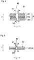
- Fig. 4 illustrates a vertical cross-sectional view of a longitudinal slit 43 formed in the central slit region S 1, and the absorbent member in sections in the vicinity of the longitudinal slit.
- Fig. 5 is a vertical cross-sectional view of a longitudinal slit 43 formed in the side slit region S2, and the absorbent member in sections in the vicinity of the longitudinal slit.
- the longitudinal slit 43 is formed in a layered structure having a five-layer structure including: a three-layer structure part formed by folding up the central absorbent sheet 402; and the layers 401, 401 of the base absorbent sheet located on the upper side and lower side of the three-layer structure part.
- the longitudinal slit 43 penetrates the five-layered structure over the entire region in the thickness direction thereof.
- the longitudinal slit 43 is formed in a layered structure having two layers made by folding up the base absorbent sheet 401.
- the longitudinal slit 43 penetrates the two-layered structure over the entire region in the thickness direction thereof.
- a portion of the plurality of layers of the absorbent sheets forming the layered structure is in a non-joined state in a section where each longitudinal slit 43 is formed.
- the expression "the absorbent sheets are in a non-joined state” means that the absorbent sheets adjacent to one another in the thickness direction are not joined by any of various types of joining means such as compression-bonding, adhesion, fusion-bonding, etc.
- Fig. 4 illustrates a state in which all of the absorbent sheets adjacent to one another in the thickness direction are in a non-joined state.
- a void is provided between adjacent absorbent sheets with the aim of visually illustrating that the absorbent sheets are in a non-joined state (likewise for Fig. 5 ).
- the void may or may not be formed. It is preferable to form a void between adjacent absorbent sheets from the viewpoint of increasing liquid retention capacity at the time of repeatedly absorbing liquid and to prevent a reduction in absorption speed.
- all of the absorbent sheets adjacent to one another in the thickness direction are in a non-joined state, but it will suffice if the non-joined state between absorbent sheets is present in at least one section of the adjacent absorbent sheets.
- the absorbent sheet has a flat shape, but microscopically, the surface of the absorbent sheet has fine projections and depressions.
- voids are created between the absorbent sheets simply by superposing the absorbent sheets. These voids are maintained so long as the layered structure of the absorbent sheets is not intentionally compressed.
- the absorbent sheets adjacent to one another in the thickness direction are in a non-joined state in a section where each longitudinal slit 43 is formed, when fluid excreted to the napkin 1 reaches the absorbent member 4 through the topsheet 2 and flows into the longitudinal slits 43, the liquid diffuses smoothly in the planar direction of the absorbent member 4 through the inner surfaces of each longitudinal slit 43.
- liquid is easily drawn in by capillary action, and thus, liquid is diffused in the planar direction even more easily. As a result, liquid absorption speed is increased.
- each side slit region S2 As in the central slit region S1, a section, in which each longitudinal slit 43 is formed, of each side slit region S2 has the two-layered structure, which constitutes each side slit region S2, of the absorbent sheets which is in a non-joined state.
- liquid absorption speed is increased according to the same mechanism as in the central slit region S1.
- the longitudinal slit 43's length in the lateral direction Y is viewed along the thickness direction T of the absorbent member 4, the slit's length W1 on the topsheet side is longer than the slit's length W2 on the backsheet side.
- the longitudinal slit 43's length in the lateral direction Y is illustrated so as to gradually decrease continuously from the topsheet side to the backsheet side.
- the longitudinal slit 43's length in the lateral direction Y does not have to change in this manner, and for example, the length may decrease stepwise from the topsheet side to the backsheet side.
- each longitudinal slit 43 has this structure, external force applied to the napkin 1 is less likely to be transmitted to the backsheet side of the absorbent member 4 in a state where the napkin 1 is worn, and thus, the napkin 1 can be fixed stably to underwear. Because external force is less likely to be transmitted to the backsheet side of the absorbent member 4, the flat shape on the backsheet side of the absorbent member 4 can be maintained, and this also allows the napkin 1 to be fixed stably to underwear. As a result, the napkin 1 is less likely to move out of place from its proper attachment position even when external force is applied to the napkin 1, and thus, reduction in absorptivity and degradation in comfortableness when worn are prevented effectively.
- the cross-sectional shape of the longitudinal slit 43 along the thickness direction T of the absorbent member 4 can be observed at a magnification of 20x to 100x with a microscope (e.g. VHX-1000 from Keyence Corporation).
- a cross section along the thickness direction T of the absorbent member 4 can be formed, for example, by cutting the absorbent member 4 with a single-edged razor from Feather Safety Razor Co., Ltd.
- the ratio W1/W2 between the aforementioned lengths W1 and W2 is preferably 5 or greater, more preferably 10 or greater.
- W1/W2 is preferably 80 or less, more preferably 60 or less.
- W1/W2 is preferably from 5 to 80 inclusive, more preferably from 10 to 60 inclusive.
- the density of the absorbent sheets in each longitudinal slit's vicinity is higher than the density of the absorbent sheets in the aforementioned non-slit section 43'. In this way, liquid that has flowed into the longitudinal slit 43 can be easily drawn in between the absorbent sheets more quickly by capillary action.
- the density of the absorbent sheets in each longitudinal slit 43's vicinity is preferably at least 1.05 times, more preferably at least 1.2 times, and preferably at most twice, more preferably at most 1.8 times, the density of the absorbent sheets in the non-slit section 43.
- the density of the absorbent sheets in each longitudinal slit 43's vicinity is preferably from 1.05 times to twice, more preferably from 1.2 times to 1.8 times, the density of the absorbent sheets in the non-slit section 43.
- the aforementioned density can be measured as follows.
- an electronic balance scale electronic balance scale
- the absorbent member 4 includes, in the rear region C located more toward the rear than the excretion-section opposing region B, a plurality of rear slits 45 each extending so as to have its length direction along a direction intersecting with the longitudinal direction X of the napkin 1, as illustrated in the figure. As illustrated in Figs.
- each rear slit 45 has a shape, in a planar view, in which the position of the slit 45's central section 45a in its length direction is located more toward the front region A than the positions of both end sections 45b, 45b in its length direction, and more preferably, the rear slit 45 has a shape, in a planar view, that is curved protrudingly toward the front region A.
- the plurality of rear slits 45 are formed with an interval therebetween in the longitudinal direction X of the absorbent article.
- the length L3, in the lateral direction Y, of a rear slit region S3 formed by the rear slits 45 is shorter than the length L4, in the direction Y, of the excretion-section slit region S.
- the excretion-section slit region S is illustrated with a slightly wider area--both in the longitudinal direction X and the lateral direction Y--than the actual area in which the longitudinal slits 43 are distributed.
- the excretion-section slit region S in the present invention is the area in which the longitudinal slits 43 are distributed, and the length L4 thereof in the lateral direction Y is the distance between the outer edge of the respective longitudinal slits 44 located at opposite ends in the lateral direction Y, as illustrated in Fig. 1(b) .
- the rear slit region S3 formed by the rear slits 45 is a region inside the smallest rectangle among various rectangles having two sides along the longitudinal direction X and two sides along the lateral direction Y and surrounding the entirety of the rear slits 45 (all of the rear slits in cases where there are a plurality of slits).
- the rear slit region S3 is also illustrated with a slightly wider area for convenience of visibility etc.
- the length L3 of the rear slit region S3 in the lateral direction Y is the distance between the two outermost end sections.
- the center position 4c that bisects the absorbent member 4's length in the lateral direction substantially matches the center position 45c that bisects the rear slit 45's length in the length direction.
- the expression “substantially match” means that the center position 4c of the absorbent member 4 may be misaligned from the center position 45c of the rear slit by a length that is 10% of the absorbent member 4's length in the lateral direction.
- each of the rear slits 45, 45 in the length direction is substantially the same.
- the expression “substantially the same” means that the difference in length is within 5% of the length L3 of the rear slit region S3 in the lateral direction Y.
- the center position 45c of each of the rear slits 45, 45 substantially matches one another.
- the expression “substantially match” means that the center positions may be misaligned from one another by a length that is 5% of the absorbent member 4's length in the lateral direction.
- the two layers of the base absorbent sheet 401 forming the layered structure are in a non-joined state in a section where each rear slit 45 is formed, as with the longitudinal slits 43 formed in the aforementioned excretion-section slit region S.
- liquid absorption speed is increased also in the rear region C, and not only in the excretion-section opposing region B.
- the rear slit 45's length in the longitudinal direction X is viewed along the thickness direction of the absorbent member 4, the rear slit 45's length on the topsheet side is longer than the length on the backsheet side.
- the density of the base absorbent sheet 401 in each rear slit 45's vicinity is higher than the density of the base absorbent sheet 401 in a non-slit section located between the rear slits 45.
- the length of the rear slit 45 in the longitudinal direction X and the density in the vicinity of the rear slit 45 can be measured according to the same methods as in the case of the aforementioned longitudinal slits 43.
- the napkin 1 of the present embodiment it is possible to achieve the aforementioned advantageous effect that liquid absorption speed is increased, and in addition, achieve an advantageous effect that deep folding creases are less likely to be created in the absorbent member 4 and the napkin 1 because the absorbent member 4 deforms finely at the various sections in the excretion-section slit region, even if a force that compresses the absorbent member 4 in the lateral direction X is applied by the wearer's thighs when the napkin 1 is worn. This prevents such deep folding creases from causing an uncomfortable feel to the wearer, and also prevents liquid from flowing along the folding creases and leaking.
- the napkin 1 of the present embodiment there is no space between adjacent slit rows R1, R2, and thus, the napkin 1 is less likely to get twisted due to pressure from the thighs, compared to cases where there is a space between the slit rows R1, R2.
- sections in the slit rows R1, R2 can deform so as to conform to movement and body shape and deep folding creases are less likely to be created, but folding creases are created in sections between the slit rows when the napkin is worn, and those folding creases are likely to propagate to slit-less sections within the slit rows, thus causing twisting of the napkin.
- a difference in rigidity arises between the sections where the slit rows are provided and the section in the space between the slit rows, and this may cause the napkin to be folded at the boundary therebetween and may impair fittability to the body.
- a plurality of rear slits 45 that extend along a direction intersecting with the longitudinal direction X of the absorbent article are formed in the rear region C, the rear slit 45 having a shape, in a planar view, that is curved protrudingly toward the front region A.
- the absorbent member 4 and the napkin 1 easily deform so as to conform to the wearer's movement and body shape.
- the napkin has excellent fittability and leakage preventability and is also comfortable to wear, even though an absorbent member 4 consisting of a laminate of absorbent sheets is used.
- the length L3 of the rear slit region S3 is equal to or shorter than the length L4 of the excretion-section slit region S (L3 ⁇ L4), it is possible to achieve advantageous effects that the napkin can be prevented from excessively wedging into the gluteal cleft and the napkin can be prevented from getting twisted in the rear region C.
- the excretion region is the region that receives the greatest pressure from the thighs, and thus, it is preferable to form slits over the absorbent member's entire width to the extent possible, in order to make the napkin conform to the body's complicated shape and movement.
- the rear region hardly receives any pressure from the thighs; rather, it is more important to make the napkin conform to the body along its front/rear direction.
- Forming slits in a direction intersecting with the excretion-section opposing region B can prevent creases and twists--which are created along the napkin 1's front/rear direction in the excretion region by the pressure from the thighs--from propagating to the rear region C; and by making the width of the rear slit equal to or narrower than the width of the slit region in the excretion-section opposing region B, the rear region C can conform to the body without becoming too soft, and can deform so as to envelop the buttocks.
- the length L3 of the rear slit region S3 By designing the length L3 of the rear slit region S3 to have the same length as the length L4 of the excretion-section slit region S, it is possible to further enhance the effect of preventing the propagation, to the rear region C, of creases and twists created along the napkin 1's front/rear direction in the excretion-section opposing region B. Further, the length of each of the rear slits 45 in the length direction may be gradually shortened toward the rear of the napkin 1, or only the rearmost rear slit 45 may be made shorter than the other rear slits 45 arranged more toward the front.
- the length L3 of the rear slit region S3 matches the straight-line distance between both ends, in the length direction, of the longest rear slit 45.
- the length of each of the rear slits 45 is gradually shortened toward the rear, it is possible to effectively prevent the napkin from wedging into the gluteal cleft while allowing the napkin to conform, to a certain extent, to the body's curved shape in the front/rear direction.
- the length of the rearmost rear slit 45 is designed to be short, it is possible to prevent uncomfortableness caused by creases and folds which are created in slit-less sections located more toward the rear than the rear slits 45 and created as a result of a difference in rigidity between the slit region and the slit-less region. It is more effective particularly if the rearmost slit and the end section of the absorbent member 4 are located relatively near one another. It is further preferable if the length L3 of the rear slit region 45 is from 50% to 100% inclusive of the length L4 of the excretion-section slit region S.
- each rear slit 45 in a shape in which the slit's central section 45a in its length direction is located more toward the front region than the positions of both end sections 45b, 45b in its length direction, the overlapping length between the rear slit 45 and a straight line extending along the direction orthogonal to the transporting direction can be reduced, and thus, the absorbent member etc.
- the rear slit 45 has a shape, in a planar view, that is curved protrudingly toward the front region, and for example, has an arc shape, a parabolic shape, or a U-shape.
- the longitudinal slit 43's length L2 (cf. Fig. 3 ) along the longitudinal direction X in the excretion-section slit region S is preferably 10 mm or greater, more preferably 15 mm or greater, and preferably 35 mm or less, more preferably 30 mm or less, and preferably from 10 mm to 35 mm inclusive, more preferably from 15 mm to 30 mm inclusive.
- the distance L5 (cf. Fig. 3 ) between the longitudinal slits 43 within the same slit row in the excretion-section slit region S is preferably 3 mm or greater, more preferably 7 mm or greater, and preferably 20 mm or less, more preferably 15 mm or less, and preferably from 3 mm to 20 mm inclusive, more preferably from 7 mm to 15 mm inclusive.
- an area from each end section of the absorbent member 4 to a point that is preferably at least 5 mm, more preferably at least 7.5 mm, inward from the end section preferably constitutes a non-slit section wherein no longitudinal slit 43 is formed.
- an area preferably up to 15 mm, more preferably up to 12.5 mm preferably constitutes a non-slit section.
- an area from each end section to a point that is from 5 mm to 15 mm, more preferably from 7.5 mm to 12.5 mm, from the end section constitutes a non-slit section wherein no longitudinal slit 43 is formed.
- the "end section" of the absorbent member 4 refers to the absorbent member 4's lateral side edge extending along the longitudinal direction X.
- the length L4 of the excretion-section slit region S in the lateral direction Y is preferably 30% or greater, more preferably 40% or greater, and preferably 85% or less, more preferably 75% or less, of the absorbent member 4's length in the direction Y in the excretion-section opposing region B.
- the length L4 of the excretion-section slit region S in the lateral direction Y is preferably 30 mm or greater, more preferably 40 mm or greater, and preferably 55 mm or less, more preferably 45 mm or less.
- the length L3, in the lateral direction Y, of the rear slit region S3 formed by the rear slits 45 is preferably 30% or greater, more preferably 40% or greater, and preferably 65% or less, more preferably 55% or less, of the absorbent member 4's length in the same direction Y in the section where the rear slits 45 are provided.
- the ratio of the length L3, in the lateral direction Y, of the rear slit region S3 formed by the rear slits 45 to the length L4 of the excretion-section slit region S in the lateral direction Y is preferably 1 or less, more preferably 5/6 or less, and preferably 2/5 or greater, more preferably 1/2 or greater.
- the length L3, in the lateral direction Y, of the rear slit region formed by the rear slits 45 is preferably 20 mm or greater, more preferably 25 mm or greater, and preferably 50 mm or less, more preferably 45 mm or less.
- the rear slit 45's length L6 (cf. Fig. 7(a) ) in the longitudinal direction X is preferably 5% or greater, more preferably 7.5% or greater, and preferably 17.5% or less, more preferably 15% or less, of the length L3 in the lateral direction Y.
- the absorbent member 4 of the napkin 1 of the present embodiment includes, in the excretion-section opposing region B, the multi-layer section 42 in which the number of layers of absorbent sheets is larger than that in sections located in its periphery, and the central slit region S1 is formed in the multi-layer section 42.
- the rear slits 45 are formed in a section that is located in the rear of the multi-layer section 42 and that has a smaller number of layers of absorbent sheets than the multi-layer section 42.
- the absorbent member etc. after the formation of the slits may be pulled in the transporting direction and fixed between e.g. upper and lower sheets in this state; in this way, a gap 46 in which the rear slit 45 is opened can be formed in the slit's central section 45a in the length direction, as illustrated in Fig. 7 .
- the central section 45a is located more toward the front region than the positions of both end sections 45b, 45b, and the central section 45a has a gap 46 formed by opening the slit.
- deformability into a shape that conforms to the body shape is further improved. If, however, sections other than the central section 45a are opened widely, absorption in sections overlapping the rear slits 45 may be inhibited. Thus, it is preferable that the rear slit 45 has non-opened regions in the vicinity of the respective end sections 45b in the length direction.
- rear slits 45 By forming the rear slits 45 in a section which is located in the rear of the multi-layer section 42 and which has a lower rigidity than the multi-layer section, it is possible to moderately neck-in the absorbent member etc. by pulling, in the transporting direction, the absorbent member etc. after the formation of the slits, and it is also possible to easily form rear slits 45 each having a gap in the central section 45a and slit-non-opened regions in the respective end sections 45b, 45b.
- the width L7 (cf. Fig. 7(a) ) in the central section 45a is preferably 0.05% or greater, more preferably 0.075% or greater, and preferably 10% or less, more preferably 8% or less, of the length L3, in the lateral direction Y, of the rear slit region S3 formed by the rear slits 45.
- the gap 46 in the central section 45a of the rear slit 45 is of a width that disappears when the absorbent member 4 is curved along the body shape during use of the napkin 1.
- the rear slits 45 in the absorbent member 4 of the present embodiment are formed in such a manner that, among two rear slits adjacent to one another in the longitudinal direction X of the napkin, the rear end position P1 of the rear slit located in the front is located more toward the front than the front end position P2 of the rear slit located in the rear.
- the absorbent member is curved so that either the opened apex closes or the opposing sides of the opening slightly overlap; this structure is also advantageous in terms of easy deformability so as to conform to the body shape. From this viewpoint, the distance L8 ( Fig.
- the absorbent member 4 in the present embodiment has, in the absorbent member 4's peripheral edge section, an annular non-slit region in which there are no slits.
- FIG. 8 schematically illustrates a process for manufacturing an absorbent member 4 of the present embodiment.
- This process for manufacturing an absorbent member 4 employs a cutting device 60 including: a cutter roller 61 that has a multitude of cutting blades 63 formed on its peripheral surface in a manner dispersed in the roller's circumferential direction and axial direction; and an anvil roller 62 that receives the cutting blades 63 of the cutter roller 61.
- This process also uses a nipping device 66 including a pair of nip rollers 64, 65 each having a smooth surface.
- the cutter roller 61 and the anvil roller 62 are arranged in such a manner that their axial centers are parallel to one another.
- a clearance may be provided between the cutter roller 61 and the anvil roller 62, or the two rollers may be in contact with one another.
- the cutting blades 63 located on the peripheral surface of the cutter roller 61 are formed and arranged so as to match the shapes of the slits 43, 45 to be formed in the target absorbent member 4. It should be noted that Fig. 8 illustrates only the cutting blades 63 for forming the longitudinal slits 43.
- the pair of nip rollers 64, 65 is arranged in such a manner that their axial centers are parallel to one another.
- a clearance may be provided between the pair of nip rollers 64, 65, or the two rollers may be in contact with one another.
- the axial centers of the rollers 61, 62 of the cutting device 60 are parallel to the axial centers of the rollers 64, 65 of the nipping device 66.
- An original textile 4a of the absorbent member 4 which has a layered structure including the base absorbent sheet and the central absorbent sheet, is transported in the direction indicated by arrow R in Fig. 8 , and is supplied between the cutter roller 61 and the anvil roller 62 in the cutting device 60.
- the state of the thickness-wise cross section of the original textile 4a before being supplied between the rollers 61, 62 is illustrated in the circle indicated by I in Fig. 8 .
- the absorbent sheets 401, 402 are in a non-joined state.
- the cutting blades 63 which are provided on the peripheral surface of the cutter roller 61, advance into the original textile 4a along the thickness direction of the original textile 4a by compression from the rollers 61, 62.
- longitudinal slits 43 and rear slits are formed in the original textile 4a.
- the state of the thickness-wise cross section of the original textile 4a immediately after a longitudinal slit 43 has been formed is illustrated in the circle indicated by II in Fig. 8 .
- the absorbent sheets 401, 402 are in a state protruding from one surface toward the other surface because of the advancement of the cutting blade 63 into the original textile 4a.
- the "one surface” is the surface in contact with the cutter roller 61
- the “other surface” is the surface in contact with the anvil roller 62.
- the protruding absorbent sheets 401, 402 are densified by the advancement of the cutting blade 63 and are in a joined state. This densification increases the density of the absorbent sheets 401, 402 in the vicinity of the longitudinal slit 43. In sections at a distance from the longitudinal slit 43, the absorbent sheets 401, 402 are not densified, or the degree of densification is small; thus, the density is not increased, or the degree of increase in density is small.
- the original textile 4a in which slits have been formed as above, is then supplied between the pair of nip rollers 64, 65 in the nipping device 66.
- the state of the thickness-wise cross section of the original textile 4a after being nipped by the rollers 64, 65 is illustrated in the circle indicated by III in Fig. 8 .
- the protruding section-- which consists of the absorbent sheets 401, 402 and has been created in the vicinity of the longitudinal slit 43--is pressed back into the longitudinal slit 43, and the absorbent sheets 401, 402 are flattened.
- the absorbent sheets 401, 402 which have been joined together up to this point, are separated, and voids are created between the absorbent sheets 401, 402.
- the absorbent sheets 401, 402 return to their non-joined state, which is the state before the formation of the slits.
- slits (longitudinal slits 43 and rear slits 45) having the intended shapes can be formed successfully.
- topsheet 2 and the backsheet 3 Materials for forming the various members of the napkin 1 are described below.
- topsheet 2 and the backsheet 3 it is possible to use various materials conventionally used in this technical field without particular limitation.
- a liquid-permeable sheet such as one of various nonwoven fabrics subjected to a hydrophilizing treatment, or a porous film.
- the backsheet 3 it is possible to use a liquid-impermeable or water-repellent material.
- liquid-impermeable materials include: resin films; microporous moisture-permeable resin films; and laminate materials of resin films and nonwoven fabrics.
- water-repellent materials that may be used include: multilayer composite nonwoven fabrics, such as spun-bonded/melt-blown/spun-bonded nonwoven fabrics; spun-bonded nonwoven fabrics; heat-bonded nonwoven fabrics; and air-through nonwoven fabrics.
- the absorbent sheets 401, 402 constituting the absorbent member 4 it is possible to preferably use a material made into a sheet by binding together constituent fibers such as pulp, and also binding the constituent fibers and an absorbent polymer together, by means of a separately added binder, such as an adhesive or an adhesive fiber, or the absorbent polymer's adhesive force that arises when the polymer is in a wet state.
- a material made into a sheet by binding together constituent fibers such as pulp, and also binding the constituent fibers and an absorbent polymer together, by means of a separately added binder, such as an adhesive or an adhesive fiber, or the absorbent polymer's adhesive force that arises when the polymer is in a wet state.
- absorbent sheets that may be used include: pulp-containing absorbent sheets manufactured according to the method disclosed in JP H8-246395A ; dry sheets made by depositing pulverized pulp and an absorbent polymer that have been supplied on an air flow, and then binding the pulp and the polymer with an adhesive (such as a vinyl acetate adhesive or PVA); absorbent sheets obtained by applying e.g. a hot-melt adhesive between sheets of pulp-containing paper or nonwoven fabric, and then sprinkling absorbent polymer particles thereon; and absorbent sheets obtained by blending a superabsorbent polymer during a step for manufacturing a spun-bonded or melt-blown nonwoven fabric.
- an adhesive such as a vinyl acetate adhesive or PVA
- Such absorbent sheets can be used as a sheet-like absorbent member by cutting a single sheet into a predetermined shape.
- the thickness of a single absorbent sheet is preferably 0.1 mm or greater, more preferably 0.3 mm or greater, and 2 mm or less, more preferably 1.5 mm or less, and more specifically, preferably from 0.1 mm to 2 mm inclusive, more preferably from 0.3 mm to 1.5 mm inclusive.
- each of the base absorbent sheet 401 and the central absorbent sheet 402 constituting the absorbent member 4 is folded up to form a layered structure including a plurality of layers.
- a plurality of individual absorbent sheets may be layered.
- the absorbent sheet may be folded up according to various folding methods.
- the auxiliary absorbent member 41 in the present embodiment may be obtained by folding the central absorbent sheet 402 according to the various folding methods illustrated in Figs. 9(a) to 9(d) .
- the thickness of the multi-layer section 42 in the absorbent member 4 is preferably 0.7 mm or greater, more preferably 1 mm or greater, and preferably 5 mm or less, more preferably 4 mm or less, and more specifically, preferably from 0.7 mm to 5 mm inclusive, more preferably from 1 mm to 4 mm inclusive.
- the thickness in sections of the absorbent member 4 other than the multi-layer section 42 is preferably 0.3 mm or greater, more preferably 0.5 mm or greater, and preferably 3 mm or less, more preferably 2.5 mm or less, and more specifically, preferably from 0.3 mm to 3 mm inclusive, more preferably from 0.5 mm to 2.5 mm inclusive. Setting the thickness within the aforementioned range is preferable from the viewpoint of achieving high absorption performance and improving followability to the wearer's movement.
- the difference in thickness (i.e., the step) at the boundary between the multi-layer section 42 and the peripheral section or in the boundary's vicinity is preferably 2 mm or less, more preferably 1.5 mm or less.
- the aim of this range is to suppress, in the excretion-section opposing region B, the occurrence of twisting in the vicinity of the boundary between the multi-layer section 42 and a region in its peripheral section where only the main absorbent member 40 is present. If the step is too large, when the napkin 1 follows the wearer's movement while it is worn, the napkin attempts to fill in the gap created by the step, and this may result in that the napkin is prone to getting twisted because of the presence of the step. In contrast, by setting the step within the aforementioned range, the effect of suppressing the occurrence of twisting in the excretion-section opposing region B is enhanced.
- the thickness of each of the members of the absorbent member 4 is measured according to the following method.
- absorbent polymers included in the absorbent sheets 401, 402 include sodium polyacrylate, (acrylic acid-vinyl alcohol) copolymers, crosslinked sodium polyacrylate, (starch-acrylic acid) graft copolymers, (isobutylene-maleic anhydride) copolymers and saponification products thereof, and polyaspartic acid. It is preferable that both the absorbent sheets 401, 402 constituting the absorbent member 4 are absorbent sheets including an absorbent polymer, but an absorbent sheet including an absorbent polymer and an absorbent sheet not including an absorbent polymer may be used in combination as a laminate of absorbent sheets constituting the absorbent member.
- a liquid-impermeable or water-repellent resin film or a laminate of a resin film and a nonwoven fabric may be used.
- other materials include water-repellent (hydrophobic) nonwoven fabrics, such as spun-bonded nonwoven fabrics, sheets in which spun-bonded nonwoven fabrics (S) and melt-blown nonwoven fabrics (M) have been composited (e.g. SM, SMS, and SMMS), heat-rolled nonwoven fabrics, and air-through nonwoven fabrics.
- SM spun-bonded nonwoven fabrics
- M melt-blown nonwoven fabrics
- heat-rolled nonwoven fabrics e.g. SM, SMS, and SMMS
- air-through nonwoven fabrics e.g., the use of a water-repellent air-through nonwoven fabric is preferred from the viewpoint of pleasant texture and side leakage prevention.
- the napkin 1 does not have to include wings 7.
- the napkin may include rear flaps which are provided on respective sides of the absorbent assembly 5 in the rear region and which are spread out and fixed to the inner surface of underpants.
- the excretion-section slit region S may be formed only in the excretion-section opposing region B, or may extend from the excretion-section opposing region B up to a portion of the rear region C, or may extend from the excretion-section opposing region B up to a portion of the front region A and a portion of the rear region C.
- the number of layers of absorbent sheets in the multi-layer section 42 is not limited to the number of layers illustrated in Fig. 2 . Also, the difference in the number of layers of absorbent sheets between the multi-layer section 42 and sections other than the multi-layer section is not limited to the number illustrated in Fig. 2 .
- rear slits 45 there may be two, three, or five or more rear slits 45.
- rear slits with a gap 46 opened in the central section 45a and rear slits without such a gap may co-exist.
- the rear slit 45 may have a shape formed by linking two straight lines at an angle in the slit's central section.
- the aforementioned slits penetrate the absorbent member 4 as described above, the slits do not have to penetrate the absorbent member; alternatively, only a portion of the slits may be non-penetrating. Examples of non-penetrating slits include slits that are not opened on the skin-opposing surface side or the non-skin-opposing surface side of the absorbent member 4.
- a space may be provided between the slit rows R1, R2 to the extent that the effects achieved by the present invention are not impaired.
- the absorbent article of the present invention is applicable to panty liners (vaginal discharge sheets), incontinence pads, and the like.
- the absorbent article of the present invention can instantaneously absorb excreted fluid into the absorbent member, can easily deform in response to external force in a state where it is worn, and is less likely to cause uncomfortableness when worn.
Landscapes
- Health & Medical Sciences (AREA)
- Engineering & Computer Science (AREA)
- Epidemiology (AREA)
- Life Sciences & Earth Sciences (AREA)
- Heart & Thoracic Surgery (AREA)
- Vascular Medicine (AREA)
- Biomedical Technology (AREA)
- Animal Behavior & Ethology (AREA)
- General Health & Medical Sciences (AREA)
- Public Health (AREA)
- Veterinary Medicine (AREA)
- Manufacturing & Machinery (AREA)
- Mechanical Engineering (AREA)
- Absorbent Articles And Supports Therefor (AREA)
Abstract
Description
- The present invention relates to an absorbent article such as a sanitary napkin.
- Known in the art is a technique that involves providing narrow slits or grooves in an absorbent member used in an absorbent article such as a sanitary napkin or a panty liner. For example, Patent Literature 1 discloses a method for forming three regions with different rigidities in an absorbent member, wherein one of the regions is formed by forming a plurality of long narrow holes in the absorbent member by removing the material forming the absorbent member.
Patent Literature 2 discloses an absorbent article including an absorbent member that has a groove, wherein the opening width of the groove along a plane orthogonal to the thickness direction of the absorbent member decreases from one surface of the absorbent member toward the other surface thereof. - Also known in the art as an absorbent member used in an absorbent article is an absorbent member having a layered structure including two or more layers of absorbent sheets that are formed thinly by using adhesive means, such as a binder, with the aim of thinning down the absorbent member. Also known is a technique in which slits or openings are formed in the absorbent member having such a layered structure. For example,
Patent Literature 3 discloses an absorbent article that uses an absorbent member in which: an upper absorbent sheet and a lower absorbent sheet are superposed; slits are provided in each absorbent sheet in the lateral direction; and the slits are arranged so as not to overlap one another in a planar view of the absorbent sheets. -
- Patent Literature 1:
JP 2008-529721 T - Patent Literature 2:
JP 2010-273842A - Patent Literature 3:
JP 2009-153835A - In the techniques disclosed in
Patent Literatures 1 and 2, the inner surfaces of each slit or groove are made of absorbent fibers such as pulp. Thus, in the course of forming the slits or grooves, the absorbent fibers tend to be densified, which may make it difficult for liquid to diffuse to the interior of the absorbent member through the inner surfaces of the slits or grooves. This applies to the slits formed in the layered structure of absorbent sheets disclosed inPatent Literature 3. On the inner surfaces of each slit, the layered absorbent sheets tend to be densified and integrated; this causes the adjacent absorbent sheets to be joined together, thus making it difficult for liquid to diffuse to the interior of the absorbent member. - The present invention provides an absorbent article including an absorbent assembly that includes: a liquid-retentive absorbent member; a topsheet arranged on a skin-opposing surface side of the absorbent member; and a backsheet arranged on a non-skin-opposing surface side of the absorbent member, wherein:
- the absorbent assembly has: an excretion-section opposing region arranged so as to oppose an excretion section of a wearer when the absorbent article is worn; a front region arranged more toward the wearer's front side than the excretion-section opposing region; and a rear region arranged more toward the wearer's rear side than the excretion-section opposing region;
- the absorbent article has a longitudinal direction corresponding to the wearer's front/rear direction, and a lateral direction orthogonal to the longitudinal direction;
- the absorbent member has a layered structure which has absorbent sheets including pulp and which has a plurality of layers;
- the layered structure of the absorbent sheets includes: a central absorbent sheet located in the excretion-section opposing region; and base absorbent sheet that is layered on the central absorbent sheet so as to extend outward from at least a portion of a peripheral edge of the central absorbent sheet;
- a plurality of longitudinal slits are formed in a dispersed state in the excretion-section opposing region of the absorbent member, each longitudinal slit being cut toward a thickness direction of the absorbent member and along the longitudinal direction; and
- in the layered structure, at least in the excretion-section opposing region, a portion of the plurality of layers of the absorbent sheets forming the layered structure is in a non-joined state in a section where each longitudinal slit is formed.
-
- [
Fig. 1] Fig. 1(a) is a plan view illustrating a skin-opposing surface side (topsheet side) of a sanitary napkin which is an embodiment of an absorbent article of the present invention, andFig. 1(b) is a plan view illustrating only the absorbent member extracted from the sanitary napkin. - [
Fig. 2] Fig. 2 is a schematic cross-sectional view taken along line II-II ofFig. 1 . - [
Fig. 3] Figs. 3(a) and 3(b) are partially enlarged plan views of absorbent members illustrating preferred arrangements of longitudinal slits in a central slit region. - [
Fig. 4] Fig. 4 is a vertical cross-sectional view of a longitudinal slit in a central slit region. - [
Fig. 5] Fig. 5 is a vertical cross-sectional view of a longitudinal slit in a side slit region. - [
Fig. 6] Fig. 6 is a schematic cross-sectional view taken along line IV-IV ofFig. 1 . - [
Fig. 7] Fig. 7(a) is a partially enlarged plan view of a rear slit region in the sanitary napkin illustrated inFig. 1 , andFig. 7(b) is a view of another embodiment corresponding toFig. 7(a) . - [
Fig. 8] Fig. 8 is a schematic diagram illustrating steps for manufacturing the absorbent member in the sanitary napkin illustrated inFig. 1 . - [
Fig. 9] Figs. 9(a) to 9(d) are schematic cross-sectional views of auxiliary absorbent members illustrating other examples of methods for folding up the absorbent sheet. - An absorbent article of the present invention is described below according to a sanitary napkin, which is a preferred embodiment of the invention, with reference to the drawings. As illustrated in
Figs. 1 and2 , a napkin 1 of the present embodiment includes anabsorbent assembly 5 that includes: a liquid-retentiveabsorbent member 4; atopsheet 2 arranged on the skin-opposing surface side of theabsorbent member 4; and abacksheet 3 arranged on the non-skin-opposing surface side of theabsorbent member 4. The napkin has a longitudinal direction X corresponding to the wearer's front/rear direction, and a lateral direction Y orthogonal to the longitudinal direction. - It should be noted that, in the present Description, the skin-opposing surface is the surface of the absorbent article, or its constituent members (such as the absorbent assembly 5), that faces the wearer's skin when the absorbent article is worn, and the non-skin-opposing surface is the surface of the absorbent article, or its constituent members, that faces the opposite side from the skin (i.e., the garment side) when the absorbent article is worn. The longitudinal direction X matches the length direction of the absorbent article (absorbent assembly), and the lateral direction Y matches the width direction (direction orthogonal to the length direction) of the absorbent article (absorbent assembly).
- The
absorbent assembly 5 has, in the longitudinal direction X: an excretion-section opposing region B arranged so as to oppose the wearer's fluid excretion section (e.g. the introitus) when the absorbent article is worn; a front region A arranged more toward the wearer's front side (stomach side) than the excretion-section opposing region B when the article is worn; and a rear region C arranged more toward the wearer's rear side (back side) than the excretion-section opposing region B when the absorbent article is worn. - In addition to the
absorbent assembly 5, the napkin 1 includes a pair ofwings absorbent assembly 5's excretion-section opposing region B that extend along the longitudinal direction X. - It should be noted that, in the absorbent article of the present invention, in cases where there are wings as in the napkin 1 of the present embodiment, the excretion-section opposing region is the region where the wings are provided in the longitudinal direction (the length direction of the absorbent article; the X direction in the figures) of the absorbent article (i.e., is the region sandwiched between each wing's joining base on one side in the longitudinal direction and the joining base on the other side). In an absorbent article without wings, the excretion-section opposing region is the region surrounded by a first fold line and a second fold line as counted from the absorbent article's front end in the longitudinal direction, the aforementioned first and second fold lines being the two fold lines (not illustrated) that traverse the absorbent article in the lateral direction (the width direction of the absorbent article; the Y direction in the figures) and that are created when the absorbent article is folded up in three into its individually-packaged form.
- As illustrated in
Fig. 2 , thetopsheet 2 covers the entire region of the skin-opposing surface of theabsorbent member 4, and also extends outward in the lateral direction Y from theabsorbent member 4's respective lateral side edges that extend along the longitudinal direction X. On the other hand, thebacksheet 3 covers the entire region of the non-skin-opposing surface of theabsorbent member 4, and also extends outward in the lateral direction Y from theabsorbent member 4's respective lateral side edges that extend along the longitudinal direction X, and formsside flaps 6 together with later-describedside sheets 10. Thebacksheet 3 and theside sheets 10 are joined together by a known joining means, such as an adhesive, heat sealing, ultrasonic sealing, etc., in extension portions extending from theabsorbent member 4's respective lateral side edges which extend along the longitudinal direction X. Thetopsheet 2 and theabsorbent member 4, as well as thebacksheet 3 and theabsorbent member 4, may be joined by an adhesive. - As illustrated in
Fig. 2 , theabsorbent member 4 of the present embodiment has a layered structure which has baseabsorbent sheet 401 and a centralabsorbent sheet 402 and which has a plurality of layers, and includes amulti-layer section 42 in the excretion-section opposing region B, as illustrated inFigs. 1 and2 . As illustrated inFig. 2 , themulti-layer section 42 is a section where the number of layers of theabsorbent sheets absorbent member 4 is greater than sections located in its periphery. Themulti-layer section 42 in the present embodiment has a thickness that is thicker than that of sections located in its periphery, and forms a protruding section that protrudes toward thetopsheet 2 side (the napkin 1's skin-opposing surface side) in the excretion-section opposing region B. Further, theabsorbent member 4 includes: a mainabsorbent member 40 forming the outer shape of theabsorbent member 4; and an auxiliaryabsorbent member 41 that is arranged so as to overlap a portion of the mainabsorbent member 40 and that is smaller than the mainabsorbent member 40. The auxiliaryabsorbent member 41 is located at least in the excretion-section opposing region B. - The
absorbent member 4 of the present embodiment is preferably constituted only from the layered structure including theabsorbent sheets absorbent member 4 does not include a fiber-stacked structure including absorbent fibers such as pulp. In the present invention, the absorbent sheet is a sheet-like absorbent structure made by forming an absorbent material, including pulp, into a thin sheet by using an adhesive means such as a binder. - The main
absorbent member 40 consists of a structure in which the baseabsorbent sheet 401 including pulp is folded up. More specifically, the mainabsorbent member 40 is formed by inwardly folding the baseabsorbent sheet 401 at positions offold lines absorbent sheet 401 is in a state where both ends thereof are folded up (in a gate fold). At this time, the positions of thefold lines absorbent sheet 401 partially overlap one another. Thus, the mainabsorbent member 40 has a layered structure including two layers and three layers consisting of the baseabsorbent sheet 401. - On the other hand, the auxiliary
absorbent member 41 consists of a structure in which the centralabsorbent sheet 402 including pulp is folded up. More specifically, the auxiliaryabsorbent member 41 is made by: inwardly folding, along afold line 402a that extends along the longitudinal direction X, a section of the centralabsorbent sheet 402 located outward of thefold line 402a; and then inwardly folding, along afold line 402b, a section located outward of thefold line 402b toward the side of the section that has been folded first. Thefold lines absorbent sheet 402's length in the lateral direction Y into three equal parts. Thus, the centralabsorbent sheet 402 is in a state where it is folded-up in a letter fold (tri-fold). Thus, the auxiliaryabsorbent member 41 has a layered structure including three layers consisting of the centralabsorbent sheet 402. - As illustrated in
Fig. 2 , the centralabsorbent sheet 402, which is in a state where it is folded-up in a letter fold (tri-fold), is arranged inside the baseabsorbent sheet 401, which is in a state where both ends thereof are folded up (in a gate fold). Stated differently, the baseabsorbent sheet 401 and the centralabsorbent sheet 402 have a nested folded-up structure. As a result, in the layered structure including the baseabsorbent sheet 401 and the centralabsorbent sheet 402, the baseabsorbent sheet 401 is layered on the centralabsorbent sheet 402 so as to extend outward from at least a portion--more specifically, the entire region--of the peripheral edge of the centralabsorbent sheet 402. It should be noted that, because the auxiliaryabsorbent member 41 is located in the excretion-section opposing region B as described above, the centralabsorbent sheet 402 constituting the auxiliaryabsorbent member 41 is also located in the excretion-section opposing region B. - The main
absorbent member 40, which is made of a folded-up structure of the baseabsorbent sheet 401, has a substantially rectangular shape with rounded corners in a planar view, and extends from the front region A to the rear region C across the excretion-section opposing region B. On the other hand, the auxiliaryabsorbent member 41, which is made of a folded-up structure of the centralabsorbent sheet 402, has a substantially rectangular shape in a planar view, and is arranged from the excretion-section opposing region B to its vicinity in the rear region C. By arranging the auxiliaryabsorbent member 41 in a portion of the mainabsorbent member 40, the absorption capacity in a portion of theabsorbent member 4 can be increased easily and efficiently. Instead of arranging the auxiliaryabsorbent member 41 inside the mainabsorbent member 40 made of the folded-up baseabsorbent sheet 401, the auxiliaryabsorbent member 41 may be layered on the skin-opposing surface side of the baseabsorbent sheet 401 constituting the mainabsorbent member 40, or may be layered on the non-skin-opposing surface side thereof. - As illustrated in
Figs. 1 and2 , on the respective lateral sides extending along the longitudinal direction X on theabsorbent assembly 5's skin-opposing surface (thetopsheet 2's skin-opposing surface), a pair ofside sheets absorbent assembly 5 in the longitudinal direction X so as to overlap theabsorbent member 4's respective lateral sides, which extend along the longitudinal direction X, in a planar view. Each of theside sheets line 11 located in the excretion-section opposing region B; and linear second joininglines 12 located on the front and rear, in the longitudinal direction X, of the first joining line 11 (i.e., in the front region A and rear region C). The first joiningline 11 is a curved line that protrudes outward in the lateral direction Y in a planar view. The second joiningline 12 is a line (zigzag line) that extends so as to intersect with the longitudinal direction in a planar view. Theside sheet 10 is made of a water-repellent nonwoven fabric. By joining eachside sheet 10 onto theabsorbent assembly 5's skin-opposing surface (the topsheet 2) by the joininglines side sheet 10 and thetopsheet 2 is formed on a side more inward in the lateral direction Y than the joininglines Fig. 2 . Each space P is opened toward theabsorbent assembly 5's center in the lateral direction Y; thus, excreted fluid, such as menstrual blood, that flows outward from the center in the lateral direction Y is captured by the spaces P, and as a result, leakage of excreted fluid is prevented effectively. - As illustrated in
Fig. 1 , the side flaps 6 project greatly outward in the lateral direction Y in the excretion-section opposing region B. Thus, a pair ofwings absorbent assembly 5's respective lateral sides that extend along the longitudinal direction X. Further, as illustrated inFig. 1 , thetopsheet 2 and thebacksheet 3 extend outward in the longitudinal direction X from theabsorbent member 4's front end and rear end in the longitudinal direction X, and their extension portions are joined together by a known joining means--such as an adhesive, heat sealing, or ultrasonic sealing--to form end sealed portions. - The
wings 7 are used by being folded toward the non-skin-opposing surface side in the crotch section of a garment, such as underpants. As illustrated inFig. 1 , in a planar view, eachwing 7 has a substantially trapezoidal shape in which the lower base (the side longer than the upper base) is located on the side of theabsorbent assembly 5's lateral side. A wing adhesive section (not illustrated) for fixing the wing 7 (napkin 1) onto a garment such as underpants (not illustrated) is formed on the non-skin-opposing surface of eachwing 7. With the wing adhesive section, eachwing 7--which is folded back toward the non-skin-opposing surface (outer surface) in the garment's crotch section when the napkin is in use--can be attached and fixed to the crotch section. Further, an assembly adhesive section (not illustrated) for fixing theabsorbent assembly 5 onto a garment such as underpants is formed on the non-skin-opposing surface of theabsorbent assembly 5. It should be noted that, in the napkin 1, the borderline between theabsorbent assembly 5 and eachwing 7 is a straight line (not illustrated) connecting both joining bases, in the longitudinal direction X, of thewing 7. - Although not illustrated, it is preferable that the napkin 1 further includes a second sheet provided between the
absorbent member 4 and thetopsheet 2. Preferably, the second sheet is a liquid-permeable fiber sheet in which the constituent fibers are synthetic fibers. Particularly, by constituting the second sheet from fibers obtained by subjecting hydrophobic synthetic fibers to a hydrophilic treatment, liquid diffusibility can be kept low. Further, from the viewpoint of mechanical compatibility as well as reduced diffusibility, it is preferable that the synthetic fiber constituting the second sheet is a weakly hydrophilic fiber. The second sheet may be formed by using fibers made of a resin--such as polyethylene, polypropylene, a polyester such as polyethylene terephthalate or polybutylene terephthalate, or a polyamide such as nylon-6 or nylon-66--singly, or by mixing two or more types of the fibers. Herein, "mixing" encompasses the use of making two or more types of resins having different melting points into a core-sheath-type conjugate fiber or a side-by-side conjugate fiber. - In order to make the second sheet into a sheet having high permeability and moderate diffusibility, the thickness is preferably 0.15 mm or greater, more preferably 0.2 mm or greater, and preferably 0.4 mm or less, more preferably 0.3 mm or less. In consideration of the state in which the diaper is worn, the thickness is measured under a load of 0.5 kPa.
- As for the second sheet, it is possible to preferably use an air-through nonwoven fabric in which the intersecting points between intersecting synthetic fibers are joined by fusion-bonding according to an air-through method. It should be noted that, other than air-through nonwoven fabrics, it is possible to use, for example, point-bonded nonwoven fabrics, spun-bonded nonwoven fabrics, or spun-laced nonwoven fabrics. In cases where the second sheet is an air-through nonwoven fabric, the basis weight is preferably from 15 g/m2 to 40 g/m2 inclusive.
- It is preferable that the
topsheet 2 and the second sheet are partially fixed. In this way, thetopsheet 2 can be prevented from rising up, and also, the adhesion between thetopsheet 2 and the second sheet is improved and liquid can be transferred more easily. For the same reasons, it is preferable that the second sheet and theabsorbent member 4 are partially fixed. Here, "partially fixed" means that there are fixing portions consisting of dots or lines, and, although the fixing portions do not have to be distributed evenly, the fixing portions are distributed over the entire sheet surface, and the sheets to be fixed are not fixed over the entire surface. The area of the fixing portions is preferably from about 10% to 70% inclusive with respect to the entire area of the sheet to be fixed. More specifically, thetopsheet 2 and the second sheet are partially fixed by intermittently applying an adhesive or by intermittently applying heat sealing. In cases of intermittently applying an adhesive, thetopsheet 2 and the second sheet are partially bonded in a state where body fluid permeability is maintained between thetopsheet 2 and the second sheet by employing known means, for example, by intermittently applying an adhesive with a slot-coating gun, by spirally applying an adhesive with a spiral spray gun, by intermittently applying an adhesive in an atomized form with a spray gun, or by applying an adhesive in dots with a dot gun. Examples of applicable adhesives that may be preferably used include hot-melt adhesives. - Examples of hot-melt adhesives include styrene-based and olefin-based adhesives. Examples of styrene-based hot-melt adhesives that may be used include styrene-butadiene-styrene (SBS) copolymers, styrene-isoprene-styrene (SIS) copolymers, styrene-ethylene-butylene-styrene (SEBS) copolymers which are hydrogenated products of SBS, and blended hot-melt adhesives in which two or more types of the above are blended. Particularly, a blended hot-melt adhesive including SIS and SBS or a blended hot-melt adhesive including SIS and SEBS is preferably used in the present invention because of the ease of balancing tack force and cohesive force. The amount of hot-melt adhesive applied is preferably from 3 g/m2 to 10 g/m2 inclusive.
- In cases of intermittently applying heat sealing, the
topsheet 2 and the second sheet are partially fusion-bonded by, for example, employing a heat-embossing roller having a plurality of projections and a flat roller, transmitting a layered sheet consisting of thetopsheet 2 and the second sheet between the heat-embossing roller and the flat roller, and embossing the layered sheet. The distance between the plurality of fusion-bonded points formed by fusion-bonding is preferably from 5 mm to 15 mm inclusive from the viewpoint of maintaining body fluid permeability while achieving moderate adhesion between thetopsheet 2 and the second sheet. - As illustrated in
Figs. 1 and2 , linear grooves, which are formed by recessing thetopsheet 2 and theabsorbent member 4 in an integrated fashion toward thebacksheet 3 side, are formed in theabsorbent assembly 5's skin-opposing surface (thetopsheet 2's skin-opposing surface). The linear grooves include:longitudinal grooves 51 that extend along the longitudinal direction X in the excretion-section opposing region B; and first and secondlateral grooves topsheet 2 and theabsorbent member 4 are compression-bonded by an adhesive, or are integrated by thermal fusion-bonding etc. - With these linear grooves, it is possible to suppress liquid diffusion in the planar direction of the
absorbent member 4, and effectively prevent liquid leakage from the periphery of the napkin 1. The width (length in the direction orthogonal to the length direction) of the linear groove and its depth can be set similarly to linear grooves employed in this type of absorbent article. Further, as regards the term "linear" as used in the linear grooves, the shape of the groove (recess) is not limited to a straight line in a planar view, but includes curved lines, and the lines may be continuous lines or broken lines. For example, the linear groove may consist of a row of a multitude of discontinuous embossed dots. It should be noted that, as illustrated inFig. 1 , the napkin 1 of the present embodiment is formed so as to have left-right symmetry with respect to a center line (not illustrated) that divides theabsorbent assembly 5 in two in the lateral direction Y. - As illustrated in
Figs. 1 and3 , in the napkin 1 of the present embodiment, theabsorbent member 4 includes, in the excretion-section opposing region B, an excretion-section slit region S in which a plurality oflongitudinal slits 43 extending along the longitudinal direction X are formed in a dispersed state. The excretion-section slit region S includes a central slit region S1 and side slit regions S2. The central slit region S1 is located in a central section, in the lateral direction Y, of theabsorbent member 4 in the excretion-section opposing region B. The central slit region S1 substantially matches themulti-layer section 42, i.e., the section where the baseabsorbent sheet 401 and the centralabsorbent sheet 402 are layered. The side slit regions S2 are located outward, in the lateral direction Y, of the central slit region S1. The side slit regions S2 substantially match the sections in which theabsorbent member 4 is formed only of the baseabsorbent sheet 401. - The
longitudinal slits 43 in the excretion-section slit region S are formed in a dispersed state in both the longitudinal direction X and the lateral direction Y. As illustrated inFig. 2 , eachlongitudinal slit 43 is formed by cutting theabsorbent member 4 toward the thickness direction thereof, and preferably penetrates the layered structure including theabsorbent sheets absorbent member 4. Preferably, thelongitudinal slits 43 are not formed in thetopsheet 2 and thebacksheet 3, which are respectively arranged on the upper side and the lower side of theabsorbent member 4, and are not formed in a nonwoven fabric-made intermediate sheet that may be arranged between thetopsheet 2 and theabsorbent member 4. - The
longitudinal slits 43 are formed separately and independently from one another, and there is anon-slit section 43' located between adjacentlongitudinal slits 43. The entire region of the periphery of eachlongitudinal slit 43 is surrounded by thenon-slit section 43'. - As described above, the
longitudinal slit 43 is formed by cutting theabsorbent member 4 along the thickness direction thereof, and is constituted by a cut that substantially has no width, or is a narrow space with a width that is preferably 1.5 mm or less. In cases where thelongitudinal slit 43 has a width, the width refers to the length of thelongitudinal slit 43 in the direction orthogonal to the direction along which thelongitudinal slit 43 extends. - As illustrated in
Figs. 3(a) and 3(b) , in theabsorbent member 4, a plurality of slit rows R1, R2--each including a plurality of thelongitudinal slits 43 separated from one another in the lateral direction Y--are formed in the longitudinal direction X of the napkin 1.Figs. 3(a) and 3(b) illustrate examples in which slit rows R1--each including twolongitudinal slits 43 separated from one another in the lateral direction Y--and slit rows R2--each including threelongitudinal slits 43 separated from one another in the lateral direction Y--are formed alternately in the longitudinal direction X. However, the excretion-section slit region S only needs to include at least two slit rows arranged in the longitudinal direction X, each slit row including twolongitudinal slits 43 separated from one another in the lateral direction Y. It is, however, preferable to form three or more slit rows, more preferably four or more slit rows, and even more preferably five or more slit rows, in the longitudinal direction X. Further, as for the number of the longitudinal slits included in each slit row and separated from one another in the lateral direction X, preferably two or more longitudinal slits, more preferably three or more longitudinal slits, and even more preferably four or more longitudinal slits, are included in each slit row. - It is preferable that there is no space between the slit rows adjacent to one another in the longitudinal direction X of the napkin 1. The expression "there is no space P between adjacent slit rows" encompasses: cases where the positions of the respective end sections of
slits 43 in adjacent slit rows match one another, as illustrated inFig. 3(a) ; and cases where adjacent slit rows partially overlap one another in the longitudinal direction X, as illustrated inFig. 3(b) . In cases of arranging two slit rows in the longitudinal direction X in a partially overlapping state as illustrated inFig. 3(b) , the overlapping length L1 is preferably 20% or less, more preferably 10% or less, of the length L2, in the direction X, of each longitudinal slit constituting the slit rows. - As illustrated in
Figs. 3(a) and 3(b) , the positions of the slits in the slit rows adjacent to one another in the longitudinal direction X of the napkin 1 are misaligned in the lateral direction Y of the napkin 1. More specifically, as regards thelongitudinal slits 43 in the two slit rows R1, R2 adjacent to one another in the longitudinal direction X, it is preferable that each slit 43 in one slit row R1 is located in the central section between twoslits 43 in the other slit row R2; however, theslit 43 in one slit row R1 may be formed so as to be located closer to either one of the twoslits 43 in the other slit row R2. -
Fig. 4 illustrates a vertical cross-sectional view of alongitudinal slit 43 formed in the central slit region S 1, and the absorbent member in sections in the vicinity of the longitudinal slit.Fig. 5 is a vertical cross-sectional view of alongitudinal slit 43 formed in the side slit region S2, and the absorbent member in sections in the vicinity of the longitudinal slit. In the central slit region S1 illustrated inFig. 4 , thelongitudinal slit 43 is formed in a layered structure having a five-layer structure including: a three-layer structure part formed by folding up the centralabsorbent sheet 402; and thelayers longitudinal slit 43 penetrates the five-layered structure over the entire region in the thickness direction thereof. On the other hand, in the side slit region S2 illustrated inFig. 5 , thelongitudinal slit 43 is formed in a layered structure having two layers made by folding up the baseabsorbent sheet 401. Thelongitudinal slit 43 penetrates the two-layered structure over the entire region in the thickness direction thereof. - As illustrated in
Fig. 4 , in the five-layered structure constituting the central slit region S1, a portion of the plurality of layers of the absorbent sheets forming the layered structure is in a non-joined state in a section where eachlongitudinal slit 43 is formed. The expression "the absorbent sheets are in a non-joined state" means that the absorbent sheets adjacent to one another in the thickness direction are not joined by any of various types of joining means such as compression-bonding, adhesion, fusion-bonding, etc.Fig. 4 illustrates a state in which all of the absorbent sheets adjacent to one another in the thickness direction are in a non-joined state. In this figure, a void is provided between adjacent absorbent sheets with the aim of visually illustrating that the absorbent sheets are in a non-joined state (likewise forFig. 5 ). However, in an actual layered structure, the void may or may not be formed. It is preferable to form a void between adjacent absorbent sheets from the viewpoint of increasing liquid retention capacity at the time of repeatedly absorbing liquid and to prevent a reduction in absorption speed. Further, inFig. 4 , all of the absorbent sheets adjacent to one another in the thickness direction are in a non-joined state, but it will suffice if the non-joined state between absorbent sheets is present in at least one section of the adjacent absorbent sheets. - Macroscopically, the absorbent sheet has a flat shape, but microscopically, the surface of the absorbent sheet has fine projections and depressions. Thus, voids are created between the absorbent sheets simply by superposing the absorbent sheets. These voids are maintained so long as the layered structure of the absorbent sheets is not intentionally compressed.
- Because the absorbent sheets adjacent to one another in the thickness direction are in a non-joined state in a section where each
longitudinal slit 43 is formed, when fluid excreted to the napkin 1 reaches theabsorbent member 4 through thetopsheet 2 and flows into thelongitudinal slits 43, the liquid diffuses smoothly in the planar direction of theabsorbent member 4 through the inner surfaces of eachlongitudinal slit 43. Particularly, between absorbent sheets adjacent to one another in the thickness direction, liquid is easily drawn in by capillary action, and thus, liquid is diffused in the planar direction even more easily. As a result, liquid absorption speed is increased. - Also in the side slit regions S2, as in the central slit region S1, a section, in which each
longitudinal slit 43 is formed, of each side slit region S2 has the two-layered structure, which constitutes each side slit region S2, of the absorbent sheets which is in a non-joined state. Thus, also in the side slit regions S2, liquid absorption speed is increased according to the same mechanism as in the central slit region S1. - As illustrated in
Figs. 4 and 5 , when thelongitudinal slit 43's length in the lateral direction Y is viewed along the thickness direction T of theabsorbent member 4, the slit's length W1 on the topsheet side is longer than the slit's length W2 on the backsheet side. InFigs. 4 and 5 , thelongitudinal slit 43's length in the lateral direction Y is illustrated so as to gradually decrease continuously from the topsheet side to the backsheet side. However, thelongitudinal slit 43's length in the lateral direction Y does not have to change in this manner, and for example, the length may decrease stepwise from the topsheet side to the backsheet side. By making thelongitudinal slit 43's length W1 on the topsheet side longer than the length W2 on the backsheet side, liquid can be easily taken into eachlongitudinal slit 43, and liquid absorption speed is increased also by this configuration. Also, because eachlongitudinal slit 43 has this structure, external force applied to the napkin 1 is less likely to be transmitted to the backsheet side of theabsorbent member 4 in a state where the napkin 1 is worn, and thus, the napkin 1 can be fixed stably to underwear. Because external force is less likely to be transmitted to the backsheet side of theabsorbent member 4, the flat shape on the backsheet side of theabsorbent member 4 can be maintained, and this also allows the napkin 1 to be fixed stably to underwear. As a result, the napkin 1 is less likely to move out of place from its proper attachment position even when external force is applied to the napkin 1, and thus, reduction in absorptivity and degradation in comfortableness when worn are prevented effectively. - The cross-sectional shape of the
longitudinal slit 43 along the thickness direction T of theabsorbent member 4 can be observed at a magnification of 20x to 100x with a microscope (e.g. VHX-1000 from Keyence Corporation). A cross section along the thickness direction T of theabsorbent member 4 can be formed, for example, by cutting theabsorbent member 4 with a single-edged razor from Feather Safety Razor Co., Ltd. The ratio W1/W2 between the aforementioned lengths W1 and W2 is preferably 5 or greater, more preferably 10 or greater. Also, W1/W2 is preferably 80 or less, more preferably 60 or less. For example, W1/W2 is preferably from 5 to 80 inclusive, more preferably from 10 to 60 inclusive. - In a section where the
longitudinal slit 43 is formed, it is preferable that the density of the absorbent sheets in each longitudinal slit's vicinity is higher than the density of the absorbent sheets in the aforementionednon-slit section 43'. In this way, liquid that has flowed into thelongitudinal slit 43 can be easily drawn in between the absorbent sheets more quickly by capillary action. From the viewpoint of further enhancing this effect, the density of the absorbent sheets in each longitudinal slit 43's vicinity is preferably at least 1.05 times, more preferably at least 1.2 times, and preferably at most twice, more preferably at most 1.8 times, the density of the absorbent sheets in thenon-slit section 43. For example, the density of the absorbent sheets in each longitudinal slit 43's vicinity is preferably from 1.05 times to twice, more preferably from 1.2 times to 1.8 times, the density of the absorbent sheets in thenon-slit section 43. - The aforementioned density can be measured as follows. The density of the absorbent sheets in the longitudinal slit's vicinity, as well as in the
non-slit section 43', was measured by: cutting out the absorbent sheets in the longitudinal slit's vicinity, as well as in thenon-slit section 43', into a 3-mm-wide, 20-mm-long test specimen; measuring the thickness in the widthwise central section of the test specimen with a non-contact laser displacement meter (from Keyence Corporation; displacement meter: LK-GD500; laser head: LK-G30); measuring the mass of the test specimen with an electronic balance scale (electronic balance scale GR-300 from A&D Co., Ltd., with a precision of up to the ten-thousandths place); calculating the volume from the measured thickness; and dividing the mass by the volume. - Returning to
Fig. 1 , theabsorbent member 4 includes, in the rear region C located more toward the rear than the excretion-section opposing region B, a plurality ofrear slits 45 each extending so as to have its length direction along a direction intersecting with the longitudinal direction X of the napkin 1, as illustrated in the figure. As illustrated inFigs. 1(b) ,6, and 7(a) , eachrear slit 45 has a shape, in a planar view, in which the position of theslit 45'scentral section 45a in its length direction is located more toward the front region A than the positions of bothend sections rear slit 45 has a shape, in a planar view, that is curved protrudingly toward the front region A. The plurality ofrear slits 45 are formed with an interval therebetween in the longitudinal direction X of the absorbent article. - Further, as illustrated in
Fig. 1(b) , the length L3, in the lateral direction Y, of a rear slit region S3 formed by the rear slits 45 is shorter than the length L4, in the direction Y, of the excretion-section slit region S. InFig. 1(b) , for convenience of visibility, the excretion-section slit region S is illustrated with a slightly wider area--both in the longitudinal direction X and the lateral direction Y--than the actual area in which thelongitudinal slits 43 are distributed. However, the excretion-section slit region S in the present invention is the area in which thelongitudinal slits 43 are distributed, and the length L4 thereof in the lateral direction Y is the distance between the outer edge of the respective longitudinal slits 44 located at opposite ends in the lateral direction Y, as illustrated inFig. 1(b) . - Further, the rear slit region S3 formed by the rear slits 45 is a region inside the smallest rectangle among various rectangles having two sides along the longitudinal direction X and two sides along the lateral direction Y and surrounding the entirety of the rear slits 45 (all of the rear slits in cases where there are a plurality of slits). In
Fig. 1(b) , the rear slit region S3 is also illustrated with a slightly wider area for convenience of visibility etc. In cases where a plurality ofrear slits 45 are formed in the longitudinal direction X with their positions staggered in the lateral direction Y as illustrated inFig. 7(b) , the length L3 of the rear slit region S3 in the lateral direction Y is the distance between the two outermost end sections. - As illustrated in
Fig. 7(a) , in the napkin 1 of the present embodiment, thecenter position 4c that bisects theabsorbent member 4's length in the lateral direction substantially matches thecenter position 45c that bisects the rear slit 45's length in the length direction. Here, the expression "substantially match" means that thecenter position 4c of theabsorbent member 4 may be misaligned from thecenter position 45c of the rear slit by a length that is 10% of theabsorbent member 4's length in the lateral direction. - The length of each of the
rear slits center position 45c of each of therear slits absorbent member 4's length in the lateral direction. - In the rear slit region S3, it is preferable that the two layers of the base
absorbent sheet 401 forming the layered structure are in a non-joined state in a section where eachrear slit 45 is formed, as with thelongitudinal slits 43 formed in the aforementioned excretion-section slit region S. In this way, liquid absorption speed is increased also in the rear region C, and not only in the excretion-section opposing region B. From the viewpoint of further increasing liquid absorption speed, it is preferable that, when the rear slit 45's length in the longitudinal direction X is viewed along the thickness direction of theabsorbent member 4, the rear slit 45's length on the topsheet side is longer than the length on the backsheet side. From the same viewpoint, it is preferable that the density of the baseabsorbent sheet 401 in each rear slit 45's vicinity is higher than the density of the baseabsorbent sheet 401 in a non-slit section located between therear slits 45. The length of therear slit 45 in the longitudinal direction X and the density in the vicinity of therear slit 45 can be measured according to the same methods as in the case of the aforementionedlongitudinal slits 43. - According to the napkin 1 of the present embodiment, it is possible to achieve the aforementioned advantageous effect that liquid absorption speed is increased, and in addition, achieve an advantageous effect that deep folding creases are less likely to be created in the
absorbent member 4 and the napkin 1 because theabsorbent member 4 deforms finely at the various sections in the excretion-section slit region, even if a force that compresses theabsorbent member 4 in the lateral direction X is applied by the wearer's thighs when the napkin 1 is worn. This prevents such deep folding creases from causing an uncomfortable feel to the wearer, and also prevents liquid from flowing along the folding creases and leaking. Particularly, in the napkin 1 of the present embodiment, there is no space between adjacent slit rows R1, R2, and thus, the napkin 1 is less likely to get twisted due to pressure from the thighs, compared to cases where there is a space between the slit rows R1, R2. In cases where there is a space between adjacent slit rows R1, R2, sections in the slit rows R1, R2 can deform so as to conform to movement and body shape and deep folding creases are less likely to be created, but folding creases are created in sections between the slit rows when the napkin is worn, and those folding creases are likely to propagate to slit-less sections within the slit rows, thus causing twisting of the napkin. Furthermore, a difference in rigidity arises between the sections where the slit rows are provided and the section in the space between the slit rows, and this may cause the napkin to be folded at the boundary therebetween and may impair fittability to the body. - Moreover, in the napkin 1 of the present embodiment, a plurality of
rear slits 45 that extend along a direction intersecting with the longitudinal direction X of the absorbent article are formed in the rear region C, therear slit 45 having a shape, in a planar view, that is curved protrudingly toward the front region A. Thus, even in sections that extend from the vicinity of the rear end section of the excretion-section opposing region B up to the rear region C and that need to be curved along the front/rear direction so as to conform to the body shape while receiving force from the thighs, theabsorbent member 4 and the napkin 1 easily deform so as to conform to the wearer's movement and body shape. Thus, the napkin has excellent fittability and leakage preventability and is also comfortable to wear, even though anabsorbent member 4 consisting of a laminate of absorbent sheets is used. - Further, because the length L3 of the rear slit region S3 is equal to or shorter than the length L4 of the excretion-section slit region S (L3≤L4), it is possible to achieve advantageous effects that the napkin can be prevented from excessively wedging into the gluteal cleft and the napkin can be prevented from getting twisted in the rear region C. The excretion region is the region that receives the greatest pressure from the thighs, and thus, it is preferable to form slits over the absorbent member's entire width to the extent possible, in order to make the napkin conform to the body's complicated shape and movement. However, the rear region hardly receives any pressure from the thighs; rather, it is more important to make the napkin conform to the body along its front/rear direction. Forming slits in a direction intersecting with the excretion-section opposing region B can prevent creases and twists--which are created along the napkin 1's front/rear direction in the excretion region by the pressure from the thighs--from propagating to the rear region C; and by making the width of the rear slit equal to or narrower than the width of the slit region in the excretion-section opposing region B, the rear region C can conform to the body without becoming too soft, and can deform so as to envelop the buttocks. By designing the length L3 of the rear slit region S3 to have the same length as the length L4 of the excretion-section slit region S, it is possible to further enhance the effect of preventing the propagation, to the rear region C, of creases and twists created along the napkin 1's front/rear direction in the excretion-section opposing region B. Further, the length of each of the
rear slits 45 in the length direction may be gradually shortened toward the rear of the napkin 1, or only the rearmost rear slit 45 may be made shorter than the otherrear slits 45 arranged more toward the front. It should be noted that, in cases where the lengths of the plurality ofrear slits 45 are different from one another and their center positions, in the length direction, are aligned, the length L3 of the rear slit region S3 matches the straight-line distance between both ends, in the length direction, of the longest rear slit 45. In cases where the length of each of therear slits 45 is gradually shortened toward the rear, it is possible to effectively prevent the napkin from wedging into the gluteal cleft while allowing the napkin to conform, to a certain extent, to the body's curved shape in the front/rear direction. Further, by designing the length of the rearmost rear slit 45 to be short, it is possible to prevent uncomfortableness caused by creases and folds which are created in slit-less sections located more toward the rear than therear slits 45 and created as a result of a difference in rigidity between the slit region and the slit-less region. It is more effective particularly if the rearmost slit and the end section of theabsorbent member 4 are located relatively near one another. It is further preferable if the length L3 of therear slit region 45 is from 50% to 100% inclusive of the length L4 of the excretion-section slit region S. - In cases where the napkin manufacturing process involves a step of transporting the absorbent member, or a continuous absorbent member, along its length direction and meanwhile forming rear slits that extend along a direction orthogonal to the transporting direction, the absorbent member etc. is prone to tear when the absorbent member etc. after the formation of the slits is pulled in the transporting direction. In contrast, by forming each
rear slit 45 in a shape in which the slit'scentral section 45a in its length direction is located more toward the front region than the positions of bothend sections rear slit 45 and a straight line extending along the direction orthogonal to the transporting direction can be reduced, and thus, the absorbent member etc. can be reliably prevented from tearing. From the viewpoint of workability, the ease of forming a gap (described below), and the prevention of tearing of the absorbent member etc. during transportation, it is preferable that therear slit 45 has a shape, in a planar view, that is curved protrudingly toward the front region, and for example, has an arc shape, a parabolic shape, or a U-shape. - From the viewpoint of achieving the aforementioned effects even more reliably, it is preferable that the
absorbent member 4 has one or more of the following features. The longitudinal slit 43's length L2 (cf.Fig. 3 ) along the longitudinal direction X in the excretion-section slit region S is preferably 10 mm or greater, more preferably 15 mm or greater, and preferably 35 mm or less, more preferably 30 mm or less, and preferably from 10 mm to 35 mm inclusive, more preferably from 15 mm to 30 mm inclusive. - The distance L5 (cf.
Fig. 3 ) between thelongitudinal slits 43 within the same slit row in the excretion-section slit region S is preferably 3 mm or greater, more preferably 7 mm or greater, and preferably 20 mm or less, more preferably 15 mm or less, and preferably from 3 mm to 20 mm inclusive, more preferably from 7 mm to 15 mm inclusive. - In a region with the same length, in the longitudinal direction, as the excretion-section slit region S, an area from each end section of the
absorbent member 4 to a point that is preferably at least 5 mm, more preferably at least 7.5 mm, inward from the end section preferably constitutes a non-slit section wherein nolongitudinal slit 43 is formed. Further, an area preferably up to 15 mm, more preferably up to 12.5 mm, preferably constitutes a non-slit section. For example, it is preferable that an area from each end section to a point that is from 5 mm to 15 mm, more preferably from 7.5 mm to 12.5 mm, from the end section constitutes a non-slit section wherein nolongitudinal slit 43 is formed. Here, the "end section" of theabsorbent member 4 refers to theabsorbent member 4's lateral side edge extending along the longitudinal direction X. - The length L4 of the excretion-section slit region S in the lateral direction Y is preferably 30% or greater, more preferably 40% or greater, and preferably 85% or less, more preferably 75% or less, of the
absorbent member 4's length in the direction Y in the excretion-section opposing region B. The length L4 of the excretion-section slit region S in the lateral direction Y is preferably 30 mm or greater, more preferably 40 mm or greater, and preferably 55 mm or less, more preferably 45 mm or less. - The length L3, in the lateral direction Y, of the rear slit region S3 formed by the rear slits 45 is preferably 30% or greater, more preferably 40% or greater, and preferably 65% or less, more preferably 55% or less, of the
absorbent member 4's length in the same direction Y in the section where therear slits 45 are provided. - The ratio of the length L3, in the lateral direction Y, of the rear slit region S3 formed by the
rear slits 45 to the length L4 of the excretion-section slit region S in the lateral direction Y is preferably 1 or less, more preferably 5/6 or less, and preferably 2/5 or greater, more preferably 1/2 or greater. - The length L3, in the lateral direction Y, of the rear slit region formed by the rear slits 45 is preferably 20 mm or greater, more preferably 25 mm or greater, and preferably 50 mm or less, more preferably 45 mm or less. Further, the rear slit 45's length L6 (cf.
Fig. 7(a) ) in the longitudinal direction X is preferably 5% or greater, more preferably 7.5% or greater, and preferably 17.5% or less, more preferably 15% or less, of the length L3 in the lateral direction Y. - As illustrated in
Figs. 1(a) and2 , theabsorbent member 4 of the napkin 1 of the present embodiment includes, in the excretion-section opposing region B, themulti-layer section 42 in which the number of layers of absorbent sheets is larger than that in sections located in its periphery, and the central slit region S1 is formed in themulti-layer section 42. On the other hand, therear slits 45 are formed in a section that is located in the rear of themulti-layer section 42 and that has a smaller number of layers of absorbent sheets than themulti-layer section 42. Thus, in the central slit region S1 formed in the excretion-section opposing region B, because pressure from the thighs is applied and the body's shape and movement are complicated, rigidity is increased by increasing the layers, and thus twisting can be prevented. On the other hand, because the rear slit region is formed in a section that contacts the buttocks, deformation is not as complicated as in the central region. Further, it is possible to prevent uncomfortableness particularly when the wearer is seated. - In cases where the process for manufacturing the napkin 1 involves a step of transporting the absorbent member, or a continuous absorbent member, along its length direction and meanwhile forming rear slits that extend along a direction orthogonal to the transporting direction, the absorbent member etc. after the formation of the slits may be pulled in the transporting direction and fixed between e.g. upper and lower sheets in this state; in this way, a
gap 46 in which therear slit 45 is opened can be formed in the slit'scentral section 45a in the length direction, as illustrated inFig. 7 . In therear slit 45 of the present invention, thecentral section 45a is located more toward the front region than the positions of bothend sections central section 45a has agap 46 formed by opening the slit. Thus, deformability into a shape that conforms to the body shape is further improved. If, however, sections other than thecentral section 45a are opened widely, absorption in sections overlapping therear slits 45 may be inhibited. Thus, it is preferable that therear slit 45 has non-opened regions in the vicinity of therespective end sections 45b in the length direction. By forming therear slits 45 in a section which is located in the rear of themulti-layer section 42 and which has a lower rigidity than the multi-layer section, it is possible to moderately neck-in the absorbent member etc. by pulling, in the transporting direction, the absorbent member etc. after the formation of the slits, and it is also possible to easily formrear slits 45 each having a gap in thecentral section 45a and slit-non-opened regions in therespective end sections - From the viewpoint of improving deformability by the
rear slits 45 and also preventing absorption from being inhibited by the formation of an opening over the entire length of the slit, in eachrear slit 45 having agap 46 in itscentral section 45a, the width L7 (cf.Fig. 7(a) ) in thecentral section 45a is preferably 0.05% or greater, more preferably 0.075% or greater, and preferably 10% or less, more preferably 8% or less, of the length L3, in the lateral direction Y, of the rear slit region S3 formed by the rear slits 45. From the same viewpoint, theslit 45's width L7 (cf.Fig. 7(a) ) in thecentral section 45a is preferably 0.3% or greater, more preferably 0.5% or greater, and preferably 50% or less, more preferably 35% or less, of the rear slit 45's length L6 in the longitudinal direction X. From the viewpoint of preventing the inhibition of absorption, it is preferable that thegap 46 in thecentral section 45a of therear slit 45 is of a width that disappears when theabsorbent member 4 is curved along the body shape during use of the napkin 1. - Further, as illustrated in
Fig. 1(b) , therear slits 45 in theabsorbent member 4 of the present embodiment are formed in such a manner that, among two rear slits adjacent to one another in the longitudinal direction X of the napkin, the rear end position P1 of the rear slit located in the front is located more toward the front than the front end position P2 of the rear slit located in the rear. By arranging therear slits 45 in this way, a slit-less region can be formed between adjacentrear slits 45 in the longitudinal direction X. Thus, at the time of forming a slit in the absorbent member during product processing, pressure from a slitting blade can be prevented from being dispersed in the width direction of the absorbent member, and a slit can be formed neatly from the apex to both end sections. Further, when the rear slits are attached along the buttocks, the absorbent member is curved so that either the opened apex closes or the opposing sides of the opening slightly overlap; this structure is also advantageous in terms of easy deformability so as to conform to the body shape. From this viewpoint, the distance L8 (Fig. 1(b) ) between the rear end position P1 of the front-side rear slit and the front end position P2 of the adjacent slit on the rear side in the longitudinal direction X is preferably 2 mm or greater, more preferably 4 mm or greater. From the viewpoint of fittability to the buttocks, the distance L8 is preferably 10 mm or less, more preferably 7 mm or less. From the same viewpoint, the distance L8 is preferably 3% or greater, more preferably 5% or greater, and preferably 30% or less, more preferably 40% or less, of the length L3 of the rear slit region S3 formed by the rear slits 45. It should be noted that, as illustrated inFig. 1(b) , theabsorbent member 4 in the present embodiment has, in theabsorbent member 4's peripheral edge section, an annular non-slit region in which there are no slits. -
Fig. 8 schematically illustrates a process for manufacturing anabsorbent member 4 of the present embodiment. This process for manufacturing anabsorbent member 4 employs acutting device 60 including: acutter roller 61 that has a multitude of cuttingblades 63 formed on its peripheral surface in a manner dispersed in the roller's circumferential direction and axial direction; and ananvil roller 62 that receives thecutting blades 63 of thecutter roller 61. This process also uses anipping device 66 including a pair of niprollers - In the
cutting device 60, thecutter roller 61 and theanvil roller 62 are arranged in such a manner that their axial centers are parallel to one another. A clearance may be provided between thecutter roller 61 and theanvil roller 62, or the two rollers may be in contact with one another. Thecutting blades 63 located on the peripheral surface of thecutter roller 61 are formed and arranged so as to match the shapes of theslits absorbent member 4. It should be noted thatFig. 8 illustrates only thecutting blades 63 for forming thelongitudinal slits 43. In thenipping device 66, the pair of niprollers rollers rollers device 60 are parallel to the axial centers of therollers nipping device 66. - An
original textile 4a of theabsorbent member 4, which has a layered structure including the base absorbent sheet and the central absorbent sheet, is transported in the direction indicated by arrow R inFig. 8 , and is supplied between thecutter roller 61 and theanvil roller 62 in thecutting device 60. The state of the thickness-wise cross section of theoriginal textile 4a before being supplied between therollers Fig. 8 . In theoriginal textile 4a before being supplied between therollers absorbent sheets - When the
original textile 4a is supplied between therollers cutting blades 63, which are provided on the peripheral surface of thecutter roller 61, advance into theoriginal textile 4a along the thickness direction of theoriginal textile 4a by compression from therollers longitudinal slits 43 and rear slits (not illustrated) are formed in theoriginal textile 4a. The state of the thickness-wise cross section of theoriginal textile 4a immediately after alongitudinal slit 43 has been formed is illustrated in the circle indicated by II inFig. 8 . Immediately after the formation of alongitudinal slit 43, in a section in the vicinity of where thelongitudinal slit 43 has been formed, theabsorbent sheets cutting blade 63 into theoriginal textile 4a. The "one surface" is the surface in contact with thecutter roller 61, and the "other surface" is the surface in contact with theanvil roller 62. - In addition to this protruding state, in a section in the vicinity of where the
longitudinal slit 43 has been formed, the protrudingabsorbent sheets cutting blade 63 and are in a joined state. This densification increases the density of theabsorbent sheets longitudinal slit 43. In sections at a distance from thelongitudinal slit 43, theabsorbent sheets - The
original textile 4a, in which slits have been formed as above, is then supplied between the pair of niprollers nipping device 66. The state of the thickness-wise cross section of theoriginal textile 4a after being nipped by therollers Fig. 8 . By being nipped by therollers absorbent sheets longitudinal slit 43--is pressed back into thelongitudinal slit 43, and theabsorbent sheets absorbent sheets absorbent sheets absorbent sheets - When the
cutting blades 63 provided on thecutter roller 61 of the cuttingdevice 60 advance into theoriginal textile 4a in the thickness direction, the closer the absorbent sheet is located to thecutter roller 61, the greater the extent of cutting by each cuttingblade 63; conversely, the farther the absorbent sheet is located from thecutter roller 61, the smaller the extent of cutting. As a result, in theoriginal textile 4a that has been flattened by being nipped by the nippingdevice 66, the closer the absorbent sheet is located to thecutter roller 61, the wider the slit width; conversely, the farther the absorbent sheet is located from thecutter roller 61, the narrower the slit width. The difference between the wide part and the narrow part in the slit width becomes more significant as the thickness of theoriginal textile 4a increases or as the number of layers of theabsorbent sheets - In this way, slits (
longitudinal slits 43 and rear slits 45) having the intended shapes can be formed successfully. - Materials for forming the various members of the napkin 1 are described below. As for the
topsheet 2 and thebacksheet 3, it is possible to use various materials conventionally used in this technical field without particular limitation. For example, for thetopsheet 2, it is possible to use a liquid-permeable sheet, such as one of various nonwoven fabrics subjected to a hydrophilizing treatment, or a porous film. For thebacksheet 3, it is possible to use a liquid-impermeable or water-repellent material. Examples of liquid-impermeable materials that may be used include: resin films; microporous moisture-permeable resin films; and laminate materials of resin films and nonwoven fabrics. Examples of water-repellent materials that may be used include: multilayer composite nonwoven fabrics, such as spun-bonded/melt-blown/spun-bonded nonwoven fabrics; spun-bonded nonwoven fabrics; heat-bonded nonwoven fabrics; and air-through nonwoven fabrics. - As for the
absorbent sheets absorbent member 4, it is possible to preferably use a material made into a sheet by binding together constituent fibers such as pulp, and also binding the constituent fibers and an absorbent polymer together, by means of a separately added binder, such as an adhesive or an adhesive fiber, or the absorbent polymer's adhesive force that arises when the polymer is in a wet state. Other examples of absorbent sheets that may be used include: pulp-containing absorbent sheets manufactured according to the method disclosed inJP H8-246395A - In the present embodiment, each of the base
absorbent sheet 401 and the centralabsorbent sheet 402 constituting theabsorbent member 4 is folded up to form a layered structure including a plurality of layers. Instead, a plurality of individual absorbent sheets may be layered. Further, the absorbent sheet may be folded up according to various folding methods. For example, the auxiliaryabsorbent member 41 in the present embodiment may be obtained by folding the centralabsorbent sheet 402 according to the various folding methods illustrated inFigs. 9(a) to 9(d) . - The thickness of the
multi-layer section 42 in theabsorbent member 4 is preferably 0.7 mm or greater, more preferably 1 mm or greater, and preferably 5 mm or less, more preferably 4 mm or less, and more specifically, preferably from 0.7 mm to 5 mm inclusive, more preferably from 1 mm to 4 mm inclusive. By setting the thickness of themulti-layer section 42 within the aforementioned range, it is possible to easily achieve both high absorption performance and an excellent feel in the excretion-section opposing region B, which is where themulti-layer section 42 is formed, when the diaper is worn. Further, in cases where the absorbent article includeswings 7 as in the napkin 1 of the present embodiment, twisting of theabsorbent member 4 in the excretion-section opposing region B can be suppressed more easily when the absorbent article is worn. Further, the thickness in sections of theabsorbent member 4 other than themulti-layer section 42 is preferably 0.3 mm or greater, more preferably 0.5 mm or greater, and preferably 3 mm or less, more preferably 2.5 mm or less, and more specifically, preferably from 0.3 mm to 3 mm inclusive, more preferably from 0.5 mm to 2.5 mm inclusive. Setting the thickness within the aforementioned range is preferable from the viewpoint of achieving high absorption performance and improving followability to the wearer's movement. - In the
absorbent member 4, the difference in thickness (i.e., the step) at the boundary between themulti-layer section 42 and the peripheral section or in the boundary's vicinity is preferably 2 mm or less, more preferably 1.5 mm or less. The aim of this range is to suppress, in the excretion-section opposing region B, the occurrence of twisting in the vicinity of the boundary between themulti-layer section 42 and a region in its peripheral section where only the mainabsorbent member 40 is present. If the step is too large, when the napkin 1 follows the wearer's movement while it is worn, the napkin attempts to fill in the gap created by the step, and this may result in that the napkin is prone to getting twisted because of the presence of the step. In contrast, by setting the step within the aforementioned range, the effect of suppressing the occurrence of twisting in the excretion-section opposing region B is enhanced. The thickness of each of the members of theabsorbent member 4 is measured according to the following method. - Method for Measuring Thickness of Absorbent Member:
- An absorbent member, which is the object to be measured, is placed on a horizontal place in such a manner that there are no creases or folds/bends, and the thickness is measured under a load of 5 cN/cm2. In the thickness measurement of the present invention, a thickness gauge (Peacock Dial Upright Gauge R5-C from Ozaki Mfg. Co., Ltd.) is used. At the time of measurement, a plate (an approx. 5-mm-thick acrylic plate) having a circular or square shape in a planar view is arranged between the tip of the thickness gauge and a section to be measured in the object; the size of the plate is adjusted so that the load is 5 cN/cm2.
- Examples of absorbent polymers included in the
absorbent sheets absorbent sheets absorbent member 4 are absorbent sheets including an absorbent polymer, but an absorbent sheet including an absorbent polymer and an absorbent sheet not including an absorbent polymer may be used in combination as a laminate of absorbent sheets constituting the absorbent member. - For the
side sheets 10, it is possible to use various materials conventionally used in this technical field without particular limitation; for example, a liquid-impermeable or water-repellent resin film or a laminate of a resin film and a nonwoven fabric may be used. Examples of other materials include water-repellent (hydrophobic) nonwoven fabrics, such as spun-bonded nonwoven fabrics, sheets in which spun-bonded nonwoven fabrics (S) and melt-blown nonwoven fabrics (M) have been composited (e.g. SM, SMS, and SMMS), heat-rolled nonwoven fabrics, and air-through nonwoven fabrics. Particularly, the use of a water-repellent air-through nonwoven fabric is preferred from the viewpoint of pleasant texture and side leakage prevention. - The present invention has been described above according to preferred embodiments thereof, but the present invention is not limited to the foregoing embodiments. For example, the napkin 1 does not have to include
wings 7. Further, the napkin may include rear flaps which are provided on respective sides of theabsorbent assembly 5 in the rear region and which are spread out and fixed to the inner surface of underpants. The excretion-section slit region S may be formed only in the excretion-section opposing region B, or may extend from the excretion-section opposing region B up to a portion of the rear region C, or may extend from the excretion-section opposing region B up to a portion of the front region A and a portion of the rear region C. Further, the number of layers of absorbent sheets in themulti-layer section 42 is not limited to the number of layers illustrated inFig. 2 . Also, the difference in the number of layers of absorbent sheets between themulti-layer section 42 and sections other than the multi-layer section is not limited to the number illustrated inFig. 2 . - Further, there may be two, three, or five or more
rear slits 45. Also, rear slits with agap 46 opened in thecentral section 45a and rear slits without such a gap may co-exist. Therear slit 45 may have a shape formed by linking two straight lines at an angle in the slit's central section. Further, although it is preferable that the aforementioned slits penetrate theabsorbent member 4 as described above, the slits do not have to penetrate the absorbent member; alternatively, only a portion of the slits may be non-penetrating. Examples of non-penetrating slits include slits that are not opened on the skin-opposing surface side or the non-skin-opposing surface side of theabsorbent member 4. - Further, although it is preferable to provide no space between two slit rows R1, R2 adjacent to one another in the longitudinal direction X as described above, a space may be provided between the slit rows R1, R2 to the extent that the effects achieved by the present invention are not impaired.
- In addition to sanitary napkins, the absorbent article of the present invention is applicable to panty liners (vaginal discharge sheets), incontinence pads, and the like.
- In relation to the foregoing embodiments of the invention, the following additional features (absorbent articles, etc.) are further disclosed.
- {1} An absorbent article comprising an absorbent assembly that includes: a liquid-retentive absorbent member; a topsheet arranged on a skin-opposing surface side of the absorbent member; and a backsheet arranged on a non-skin-opposing surface side of the absorbent member, wherein:
- the absorbent assembly has: an excretion-section opposing region arranged so as to oppose an excretion section of a wearer when the absorbent article is worn; a front region arranged more toward the wearer's front side than the excretion-section opposing region; and a rear region arranged more toward the wearer's rear side than the excretion-section opposing region;
- the absorbent article has a longitudinal direction corresponding to the wearer's front/rear direction, and a lateral direction orthogonal to the longitudinal direction;
- the absorbent member has a layered structure which has absorbent sheets including pulp and which has a plurality of layers;
- the layered structure of the absorbent sheets includes: a central absorbent sheet located in the excretion-section opposing region; and a base absorbent sheet that is layered on the central absorbent sheet so as to extend outward from at least a portion of a peripheral edge of the central absorbent sheet;
- a plurality of longitudinal slits are formed in a dispersed state in the excretion-section opposing region of the absorbent member, each longitudinal slit being cut toward a thickness direction of the absorbent member and along the longitudinal direction; and
- in the layered structure, at least in the excretion-section opposing region, a portion of the plurality of layers of the absorbent sheets forming the layered structure is in a non-joined state in a section where each longitudinal slit is formed.
- {2} The absorbent article as set forth in clause {1}, wherein, when the longitudinal slit's length in the lateral direction is viewed along the thickness direction of the absorbent member, the slit's length W1 on the topsheet side is longer than the slit's length W2 on the backsheet side.
- {3} The absorbent article as set forth in clause {2}, wherein the ratio W1/W2 between the length W1 on the topsheet side and the length W2 on the backsheet side is from 5 to 80 inclusive.
- {4} The absorbent article as set forth in any one of clauses {1} to {3}, wherein a density of the absorbent sheets in each longitudinal slit's vicinity is higher than a density of the absorbent sheets in a non-slit section located between the longitudinal slits.
- {5} The absorbent article as set forth in clause {4}, wherein the density of the absorbent sheets in each longitudinal slit's vicinity is from 1.05 times to twice the density of the absorbent sheets in the non-slit section.
- {6} The absorbent article as set forth in any one of clauses {1} to {5}, wherein:
- a plurality of slit rows are formed in the longitudinal direction, each slit row including a plurality of the longitudinal slits separated from one another in the lateral direction;
- there is no space between the slit rows adjacent to one another in the longitudinal direction; and
- the positions of the slits in the slit rows adjacent to one another in the longitudinal direction are misaligned in the lateral direction.
- {7} The absorbent article as set forth in any one of clauses {1} to {6}, wherein:
- a length of each longitudinal slit along the longitudinal direction is from 10 mm to 35 mm inclusive;
- a distance between the longitudinal slits in each slit row, which includes a plurality of the longitudinal slits separated from one another in the lateral direction, is from 3 mm to 20 mm inclusive; and
- an area from each end section of the absorbent member to a point that is from 5 mm to 15 mm inward from the end section constitutes a non-slit section.
- {8} The absorbent article as set forth in any one of clauses {1} to {7}, wherein:
- the absorbent member includes, in the rear region, rear slits that extend along a direction intersecting with the longitudinal direction;
- each rear slit has a planar shape in which the slit's central section in its length direction is located more toward the front region than positions of both end sections of the slit in its length direction; and
- the plurality of rear slits are formed with an interval therebetween in the longitudinal direction.
- {9} The absorbent article as set forth in clause {8}, wherein, in the layered structure, a portion of the plurality of layers of the absorbent sheets forming the layered structure is in a non-joined state in the rear region.
- {10} The absorbent article as set forth in clause {8} or {9}, wherein the rear slit has a shape, in a planar view, that is curved protrudingly toward the front region.
- {11} The absorbent article as set forth in any one of clauses {8} to {10}, wherein a length, in the lateral direction, of a rear slit region in which the rear slits are arranged is equal to or shorter than a length, in the lateral direction, of an excretion-section slit region in which the longitudinal slits are arranged.
- {12} The absorbent article as set forth in any one of clauses {1} to {11}, wherein:
- the excretion-section slit region in which the longitudinal slits are arranged includes a central slit region located in a central section of the absorbent member in the lateral direction, and side slit regions each located outward, in the lateral direction, of the central slit region; and
- in the central slit region, the longitudinal slits penetrate the layered structure including the central absorbent sheet and the base absorbent sheet.
- {13} The absorbent article as set forth in clause {12}, wherein, in the side slit region, the longitudinal slits are formed so as to penetrate the layered structure including the base absorbent sheet.
- {14} The absorbent article as set forth in clause {12} or {13}, wherein the section, in which each longitudinal slit is formed, of the side slit region has the layered structure of the absorbent sheets which is in a non-joined state.
- {15} The absorbent article as set forth in any one of clauses {1} to {14}, wherein the central absorbent sheet is arranged inside the base absorbent sheet which is in a state where both ends thereof are folded up.
- {16} The absorbent article as set forth in any one of clauses {1} to {15}, wherein the longitudinal slits are not formed in the topsheet which is arranged on an upper side of the absorbent member and the backsheet which is arranged on a lower side of the absorbent member.
- {17} The absorbent article as set forth in any one of clauses {1} to {16}, wherein the absorbent sheet is made into a sheet by binding constituent fibers together, and also binding the constituent fibers and an absorbent polymer together, by means of a separately added binder or an adhesive force of the absorbent polymer.
- {18} The absorbent article as set forth in any one of clauses {1} to {17}, wherein each of the base absorbent sheet and the central absorbent sheet is folded up to form a layered structure including a plurality of layers.
- {19} The absorbent article as set forth in any one of clauses {1} to {18}, wherein:
- a section where the central absorbent sheet is arranged is a multi-layer section having a thickness that is thicker than that of peripheral sections; and
- the thickness of the multi-layer section is from 0.7 mm to 5 mm inclusive.
- {20} The absorbent article as set forth in clause {19}, wherein a thickness in sections other than the multi-layer section is from 0.3 mm to 3 mm inclusive.
- {21} The absorbent article as set forth in clause {19} or {20}, wherein a difference in thickness at a boundary between the multi-layer section and the peripheral section or in the boundary's vicinity is 2 mm or less.
- {22} The absorbent article as set forth in any one of clauses {1} to {21}, wherein:
- a second sheet is provided between the absorbent member and the topsheet; and
- the topsheet and the second sheet are partially fixed.
- {23} The absorbent article as set forth in any one of clauses {1} to {22}, wherein the absorbent article comprises:
- the absorbent assembly including the absorbent member, the topsheet, and the backsheet; and
- a pair of wings extending outwardly in the lateral direction from the absorbent assembly's respective lateral sides that extend along the longitudinal direction.
- {24} The absorbent article as set forth in any one of clauses {1} to {23}, wherein the absorbent article is a sanitary napkin.
- {25} A method for manufacturing the absorbent article as set forth in clause {1}, wherein the longitudinal slits are formed by:
- a step in which an absorbent-member original textile having a layered structure including a base absorbent sheet and a central absorbent sheet is supplied between a cutter roller that has cutting blades on its peripheral surface and an anvil roller that opposes the cutter roller, and slits are formed in the original textile; and
- a step in which the original textile having the slits formed therein is supplied between a pair of rollers.
- The absorbent article of the present invention can instantaneously absorb excreted fluid into the absorbent member, can easily deform in response to external force in a state where it is worn, and is less likely to cause uncomfortableness when worn.
Claims (25)
- An absorbent article comprising an absorbent assembly that includes: a liquid-retentive absorbent member; a topsheet arranged on a skin-opposing surface side of the absorbent member; and a backsheet arranged on a non-skin-opposing surface side of the absorbent member, wherein:the absorbent assembly has: an excretion-section opposing region arranged so as to oppose an excretion section of a wearer when the absorbent article is worn; a front region arranged more toward the wearer's front side than the excretion-section opposing region; and a rear region arranged more toward the wearer's rear side than the excretion-section opposing region;the absorbent article has a longitudinal direction corresponding to the wearer's front/rear direction, and a lateral direction orthogonal to the longitudinal direction;the absorbent member has a layered structure which has absorbent sheets including pulp and which has a plurality of layers;the layered structure of the absorbent sheets includes: a central absorbent sheet located in the excretion-section opposing region; and a base absorbent sheet that is layered on the central absorbent sheet so as to extend outward from at least a portion of a peripheral edge of the central absorbent sheet;a plurality of longitudinal slits are formed in a dispersed state in the excretion-section opposing region of the absorbent member, each longitudinal slit being cut toward a thickness direction of the absorbent member and along the longitudinal direction; andin the layered structure, at least in the excretion-section opposing region, a portion of the plurality of layers of the absorbent sheets forming the layered structure is in a non-joined state in a section where each longitudinal slit is formed.
- The absorbent article according to claim 1, wherein a density of the absorbent sheets in each longitudinal slit's vicinity is higher than a density of the absorbent sheets in a non-slit section located between the longitudinal slits.
- The absorbent article according to claim 2, wherein the density of the absorbent sheets in each longitudinal slit's vicinity is from 1.05 times to 2 the density of the absorbent sheets in the non-slit section.
- The absorbent article according to any one of claims 1 to 3, wherein:a plurality of slit rows are formed in the longitudinal direction, each slit row including a plurality of the longitudinal slits separated from one another in the lateral direction;there is no space between the slit rows adjacent to one another in the longitudinal direction; andthe positions of the slits in the slit rows adjacent to one another in the longitudinal direction are misaligned in the lateral direction.
- The absorbent article according to any one of claims 1 to 4, wherein:a length of each longitudinal slit along the longitudinal direction is from 10 mm to 35 mm inclusive;a distance between the longitudinal slits in each slit row, which includes a plurality of the longitudinal slits separated from one another in the lateral direction, is from 3 mm to 20 mm inclusive; andan area from each end section of the absorbent member to a point that is from 5 mm to 15 mm inward from the end section constitutes a non-slit section.
- The absorbent article according to any one of claims 1 to 5, wherein:an excretion-section slit region in which the longitudinal slits are arranged includes: a central slit region located in a central section of the absorbent member in the lateral direction; and side slit regions each located outward, in the lateral direction, of the central slit region; andin the central slit region, the longitudinal slits penetrate the layered structure including the central absorbent sheet and the base absorbent sheet.
- The absorbent article according to claim 6, wherein, in the side slit region, the longitudinal slits are formed so as to penetrate the layered structure including the base absorbent sheet.
- The absorbent article according to claim 7 or 8, wherein the section, in which each longitudinal slit is formed, of the side slit region has the layered structure of the absorbent sheets which is in a non-joined state.
- The absorbent article according to any one of claims 1 to 8, wherein the central absorbent sheet is arranged inside the base absorbent sheet which is in a state where both ends thereof are folded up.
- The absorbent article according to any one of claims 1 to 9, wherein the longitudinal slits are not formed in the topsheet which is arranged on an upper side of the absorbent member and the backsheet which is arranged on a lower side of the absorbent member.
- The absorbent article according to any one of claims 1 to 10, wherein the absorbent sheet is made into a sheet by binding constituent fibers together, and also binding the constituent fibers and an absorbent polymer together, by means of a separately added binder or an adhesive force of the absorbent polymer.
- The absorbent article according to any one of claims 1 to 11, wherein each of the base absorbent sheet and the central absorbent sheet is folded up to form a layered structure including a plurality of layers.
- The absorbent article according to any one of claims 1 to 12, wherein:a section where the central absorbent sheet is arranged is a multi-layer section having a thickness that is thicker than that of peripheral sections; andthe thickness of the multi-layer section is from 0.7 mm to 5 mm inclusive.
- The absorbent article according to claim 13, wherein a thickness in sections other than the multi-layer section is from 0.3 mm to 3 mm inclusive.
- The absorbent article according to claim 13 or 14, wherein a difference in thickness at a boundary between the multi-layer section and the peripheral section or in the boundary's vicinity is 2 mm or less.
- The absorbent article according to any one of claims 1 to 15, wherein:a second sheet is further provided between the absorbent member and the topsheet; andthe topsheet and the second sheet are partially fixed.
- The absorbent article according to any one of claims 1 to 16, wherein the absorbent article comprises:the absorbent assembly including the absorbent member, the topsheet, and the backsheet; anda pair of wings extending outwardly in the lateral direction from the absorbent assembly's respective lateral sides that extend along the longitudinal direction.
- The absorbent article according to any one of claims 1 to 17, wherein, when the longitudinal slit's length in the lateral direction is viewed along the thickness direction of the absorbent member, the slit's length W1 on the topsheet side is longer than the slit's length W2 on the backsheet side.
- The absorbent article according to claim 18, wherein the ratio W1/W2 between the length W1 on the topsheet side and the length W2 on the backsheet side is from 5 to 80 inclusive.
- The absorbent article according to any one of claims 1 to 19, wherein:the absorbent member includes, in the rear region, rear slits that extend along a direction intersecting with the longitudinal direction;each rear slit has a planar shape in which the slit's central section in its length direction is located more toward the front region than positions of both end sections of the slit in its length direction; andthe plurality of rear slits are formed with an interval therebetween in the longitudinal direction.
- The absorbent article according to claim 20, wherein, in the layered structure, a portion of the plurality of layers of the absorbent sheets forming the layered structure is in a non-joined state in the rear region.
- The absorbent article according to claim 20 or 21, wherein the rear slit has a planar shape that is curved protrudingly toward the front region.
- The absorbent article according to any one of claims 20 to 22, wherein a length, in the lateral direction, of a rear slit region in which the rear slits are arranged is equal to or shorter than a length, in the lateral direction, of the excretion-section slit region in which the longitudinal slits are arranged.
- The absorbent article according to any one of claims 1 to 23, wherein the absorbent article is a sanitary napkin.
- A method for manufacturing the absorbent article according to claim 1, wherein the longitudinal slits are formed by:a step in which an absorbent-member original textile having a layered structure including a base absorbent sheet and a central absorbent sheet is supplied between a cutter roller that has cutting blades on its peripheral surface and an anvil roller that opposes the cutter roller, and slits are formed in the original textile; anda step in which the original textile having the slits formed therein is supplied between a pair of rollers.
Applications Claiming Priority (2)
| Application Number | Priority Date | Filing Date | Title |
|---|---|---|---|
| JP2013181675A JP5898150B2 (en) | 2013-09-02 | 2013-09-02 | Absorbent articles |
| PCT/JP2014/067670 WO2015029587A1 (en) | 2013-09-02 | 2014-07-02 | Absorbent product |
Publications (3)
| Publication Number | Publication Date |
|---|---|
| EP3042639A1 true EP3042639A1 (en) | 2016-07-13 |
| EP3042639A4 EP3042639A4 (en) | 2017-04-26 |
| EP3042639B1 EP3042639B1 (en) | 2018-09-05 |
Family
ID=52586165
Family Applications (1)
| Application Number | Title | Priority Date | Filing Date |
|---|---|---|---|
| EP14840443.7A Active EP3042639B1 (en) | 2013-09-02 | 2014-07-02 | Absorbent product |
Country Status (4)
| Country | Link |
|---|---|
| EP (1) | EP3042639B1 (en) |
| JP (1) | JP5898150B2 (en) |
| CN (1) | CN105517516B (en) |
| WO (1) | WO2015029587A1 (en) |
Cited By (3)
| Publication number | Priority date | Publication date | Assignee | Title |
|---|---|---|---|---|
| WO2019190521A1 (en) * | 2018-03-29 | 2019-10-03 | Kimberly-Clark Worldwide, Inc. | Method of manufacturing an exudate management layer for use in an absorbent article |
| WO2019190517A1 (en) * | 2018-03-29 | 2019-10-03 | Kimberly-Clark Worldwide, Inc. | Method of manufacturing an exudate management layer for use in an absorbent article |
| WO2019190520A1 (en) * | 2018-03-29 | 2019-10-03 | Kimberly-Clark Worldwide, Inc. | Method of manufacturing an exudate management layer for use in an absorbent article |
Families Citing this family (19)
| Publication number | Priority date | Publication date | Assignee | Title |
|---|---|---|---|---|
| JP5860927B2 (en) * | 2014-06-27 | 2016-02-16 | ユニ・チャーム株式会社 | Absorbent articles |
| JP5860928B2 (en) * | 2014-06-27 | 2016-02-16 | ユニ・チャーム株式会社 | Absorbent articles |
| JP6279014B2 (en) * | 2015-12-22 | 2018-02-14 | 花王株式会社 | Absorbent articles |
| WO2017110716A1 (en) * | 2015-12-22 | 2017-06-29 | 花王株式会社 | Absorbent article |
| WO2017110717A1 (en) * | 2015-12-22 | 2017-06-29 | 花王株式会社 | Absorbent article |
| JP6279015B2 (en) * | 2015-12-22 | 2018-02-14 | 花王株式会社 | Absorbent articles |
| JP6259539B2 (en) * | 2016-06-03 | 2018-01-10 | 花王株式会社 | Sanitary absorbent articles |
| JP6714435B2 (en) * | 2016-06-03 | 2020-06-24 | 花王株式会社 | Sanitary absorbent article |
| WO2017209075A1 (en) * | 2016-06-03 | 2017-12-07 | 花王株式会社 | Sanitary absorbent article |
| JP6706147B2 (en) * | 2016-06-03 | 2020-06-03 | 花王株式会社 | Sanitary absorbent article |
| JP6333911B2 (en) * | 2016-09-28 | 2018-05-30 | 花王株式会社 | Absorbent articles |
| JP2019063014A (en) * | 2017-09-28 | 2019-04-25 | 花王株式会社 | Manufacturing method of absorber |
| JP2019084139A (en) * | 2017-11-08 | 2019-06-06 | 花王株式会社 | Absorbent article |
| MX2020008306A (en) | 2018-02-28 | 2020-12-07 | Kimberly Clark Co | MULTILAYER ABSORBENT CORE AND MANUFACTURING METHODS. |
| JP6827478B2 (en) * | 2018-02-28 | 2021-02-10 | ユニ・チャーム株式会社 | Animal excrement treatment sheet |
| CN108888413A (en) * | 2018-04-08 | 2018-11-27 | 曹猛 | A kind of air permeable sanitary towel core |
| CN110538025A (en) * | 2019-10-14 | 2019-12-06 | 山东诺尔生物科技有限公司 | Device for improving liquid absorption rate of hygienic product |
| CN112914839A (en) * | 2021-02-06 | 2021-06-08 | 山东诺尔生物科技有限公司 | Bacteriostatic odor-removing absorbing article and manufacturing method thereof |
| CN114986607B (en) * | 2022-06-10 | 2024-04-12 | 诺宸股份有限公司 | Sanitary article joint cutting equipment |
Family Cites Families (17)
| Publication number | Priority date | Publication date | Assignee | Title |
|---|---|---|---|---|
| US2073410A (en) * | 1934-10-09 | 1937-03-09 | Int Cellucotton Products | Absorbent package or pad |
| DE1492430A1 (en) * | 1965-02-12 | 1970-09-03 | ||
| JPH0187720U (en) * | 1987-12-01 | 1989-06-09 | ||
| JP2963647B2 (en) | 1994-12-28 | 1999-10-18 | 伊野紙株式会社 | Absorbent sheet and method for producing the same |
| JP4731073B2 (en) * | 2001-09-27 | 2011-07-20 | 花王株式会社 | Absorbent articles |
| US20060047257A1 (en) * | 2004-08-31 | 2006-03-02 | Maria Raidel | Extensible absorbent core and absorbent article |
| JP4455241B2 (en) * | 2004-09-14 | 2010-04-21 | ユニ・チャーム株式会社 | Sanitary napkin |
| US8211078B2 (en) * | 2005-02-17 | 2012-07-03 | The Procter And Gamble Company | Sanitary napkins capable of taking complex three-dimensional shape in use |
| JP4794266B2 (en) * | 2005-10-06 | 2011-10-19 | 花王株式会社 | Absorbent articles |
| CN101795648A (en) * | 2007-06-12 | 2010-08-04 | 德科技控股有限公司 | Absorbent article with slit absorbent core |
| JP4945430B2 (en) | 2007-12-27 | 2012-06-06 | 花王株式会社 | Absorbent articles |
| JP5372484B2 (en) * | 2008-12-17 | 2013-12-18 | 花王株式会社 | Absorbent articles |
| JP5775250B2 (en) | 2009-05-28 | 2015-09-09 | 王子ホールディングス株式会社 | Method for manufacturing absorbent article |
| JP5486348B2 (en) * | 2010-02-27 | 2014-05-07 | ユニ・チャーム株式会社 | Disposable wearing items |
| JP5711515B2 (en) * | 2010-12-14 | 2015-04-30 | 花王株式会社 | Absorbent articles |
| JP6222886B2 (en) * | 2011-11-25 | 2017-11-01 | ユニ・チャーム株式会社 | Absorbent article and manufacturing method thereof |
| JP5944673B2 (en) * | 2012-01-31 | 2016-07-05 | 大王製紙株式会社 | Absorbent articles |
-
2013
- 2013-09-02 JP JP2013181675A patent/JP5898150B2/en active Active
-
2014
- 2014-07-02 EP EP14840443.7A patent/EP3042639B1/en active Active
- 2014-07-02 CN CN201480047901.4A patent/CN105517516B/en active Active
- 2014-07-02 WO PCT/JP2014/067670 patent/WO2015029587A1/en not_active Ceased
Cited By (9)
| Publication number | Priority date | Publication date | Assignee | Title |
|---|---|---|---|---|
| WO2019190521A1 (en) * | 2018-03-29 | 2019-10-03 | Kimberly-Clark Worldwide, Inc. | Method of manufacturing an exudate management layer for use in an absorbent article |
| WO2019190517A1 (en) * | 2018-03-29 | 2019-10-03 | Kimberly-Clark Worldwide, Inc. | Method of manufacturing an exudate management layer for use in an absorbent article |
| WO2019190520A1 (en) * | 2018-03-29 | 2019-10-03 | Kimberly-Clark Worldwide, Inc. | Method of manufacturing an exudate management layer for use in an absorbent article |
| CN111770742A (en) * | 2018-03-29 | 2020-10-13 | 金伯利-克拉克环球有限公司 | Method of manufacturing an exudate management layer for an absorbent article |
| CN111787893A (en) * | 2018-03-29 | 2020-10-16 | 金伯利-克拉克环球有限公司 | Method of making an exudate management layer for an absorbent article |
| RU2740084C1 (en) * | 2018-03-29 | 2021-01-11 | Кимберли-Кларк Ворлдвайд, Инк. | Method of producing a layer of spreading of waste products for use in an absorbent article |
| RU2743648C1 (en) * | 2018-03-29 | 2021-02-20 | Кимберли-Кларк Ворлдвайд, Инк. | Method of manufacturing layer of distribution of isolation products for use iт absorbent product |
| CN111787893B (en) * | 2018-03-29 | 2021-10-08 | 金伯利-克拉克环球有限公司 | Method of making an exudate management layer for an absorbent article |
| CN111770742B (en) * | 2018-03-29 | 2021-11-12 | 金伯利-克拉克环球有限公司 | Method of manufacturing an exudate management layer for an absorbent article |
Also Published As
| Publication number | Publication date |
|---|---|
| WO2015029587A1 (en) | 2015-03-05 |
| JP2015047368A (en) | 2015-03-16 |
| CN105517516B (en) | 2019-05-17 |
| CN105517516A (en) | 2016-04-20 |
| EP3042639B1 (en) | 2018-09-05 |
| JP5898150B2 (en) | 2016-04-06 |
| EP3042639A4 (en) | 2017-04-26 |
Similar Documents
| Publication | Publication Date | Title |
|---|---|---|
| EP3042639B1 (en) | Absorbent product | |
| JP6220588B2 (en) | Absorbent articles | |
| JP5738449B2 (en) | Absorbent articles | |
| JP4476563B2 (en) | Sanitary napkin | |
| US20130060218A1 (en) | Absorbent article | |
| EP1330995A2 (en) | Absorbent body for hygienic absorbent articles | |
| CN104771275B (en) | absorbent article | |
| US10660803B2 (en) | Absorbent article with multi-use protection layer | |
| AU2015397131B2 (en) | Absorbent article with non-integral side covers and non-integral wings | |
| JP6192692B2 (en) | Absorbent articles | |
| JP2005296480A (en) | Sanitary napkin | |
| JP6153427B2 (en) | Absorbent articles | |
| JP6199646B2 (en) | Absorbent articles | |
| AU2018425705B2 (en) | Absorbent article with body conforming structure | |
| CN108697564A (en) | Absorbent commodity | |
| JP6120323B2 (en) | Absorbent articles | |
| JP6629542B2 (en) | Absorbent articles | |
| JP6518062B2 (en) | Absorbent articles | |
| JP6620004B2 (en) | Absorbent articles | |
| CN114599330A (en) | absorbent articles | |
| JP6629541B2 (en) | Individual package of absorbent article | |
| JP6321897B1 (en) | Absorbent articles | |
| JP2018068440A (en) | Absorbent articles |
Legal Events
| Date | Code | Title | Description |
|---|---|---|---|
| PUAI | Public reference made under article 153(3) epc to a published international application that has entered the european phase |
Free format text: ORIGINAL CODE: 0009012 |
|
| 17P | Request for examination filed |
Effective date: 20160317 |
|
| AK | Designated contracting states |
Kind code of ref document: A1 Designated state(s): AL AT BE BG CH CY CZ DE DK EE ES FI FR GB GR HR HU IE IS IT LI LT LU LV MC MK MT NL NO PL PT RO RS SE SI SK SM TR |
|
| AX | Request for extension of the european patent |
Extension state: BA ME |
|
| DAX | Request for extension of the european patent (deleted) | ||
| A4 | Supplementary search report drawn up and despatched |
Effective date: 20170329 |
|
| RIC1 | Information provided on ipc code assigned before grant |
Ipc: A61F 13/472 20060101ALI20170323BHEP Ipc: A61F 13/535 20060101ALI20170323BHEP Ipc: A61F 13/534 20060101ALI20170323BHEP Ipc: A61F 13/539 20060101ALI20170323BHEP Ipc: A61F 13/15 20060101AFI20170323BHEP |
|
| STAA | Information on the status of an ep patent application or granted ep patent |
Free format text: STATUS: EXAMINATION IS IN PROGRESS |
|
| 17Q | First examination report despatched |
Effective date: 20171219 |
|
| GRAP | Despatch of communication of intention to grant a patent |
Free format text: ORIGINAL CODE: EPIDOSNIGR1 |
|
| STAA | Information on the status of an ep patent application or granted ep patent |
Free format text: STATUS: GRANT OF PATENT IS INTENDED |
|
| INTG | Intention to grant announced |
Effective date: 20180411 |
|
| GRAS | Grant fee paid |
Free format text: ORIGINAL CODE: EPIDOSNIGR3 |
|
| GRAA | (expected) grant |
Free format text: ORIGINAL CODE: 0009210 |
|
| STAA | Information on the status of an ep patent application or granted ep patent |
Free format text: STATUS: THE PATENT HAS BEEN GRANTED |
|
| AK | Designated contracting states |
Kind code of ref document: B1 Designated state(s): AL AT BE BG CH CY CZ DE DK EE ES FI FR GB GR HR HU IE IS IT LI LT LU LV MC MK MT NL NO PL PT RO RS SE SI SK SM TR |
|
| REG | Reference to a national code |
Ref country code: GB Ref legal event code: FG4D |
|
| REG | Reference to a national code |
Ref country code: CH Ref legal event code: EP |
|
| REG | Reference to a national code |
Ref country code: AT Ref legal event code: REF Ref document number: 1036975 Country of ref document: AT Kind code of ref document: T Effective date: 20180915 |
|
| REG | Reference to a national code |
Ref country code: IE Ref legal event code: FG4D |
|
| REG | Reference to a national code |
Ref country code: DE Ref legal event code: R096 Ref document number: 602014032016 Country of ref document: DE |
|
| REG | Reference to a national code |
Ref country code: NL Ref legal event code: FP |
|
| REG | Reference to a national code |
Ref country code: LT Ref legal event code: MG4D |
|
| PG25 | Lapsed in a contracting state [announced via postgrant information from national office to epo] |
Ref country code: RS Free format text: LAPSE BECAUSE OF FAILURE TO SUBMIT A TRANSLATION OF THE DESCRIPTION OR TO PAY THE FEE WITHIN THE PRESCRIBED TIME-LIMIT Effective date: 20180905 Ref country code: SE Free format text: LAPSE BECAUSE OF FAILURE TO SUBMIT A TRANSLATION OF THE DESCRIPTION OR TO PAY THE FEE WITHIN THE PRESCRIBED TIME-LIMIT Effective date: 20180905 Ref country code: BG Free format text: LAPSE BECAUSE OF FAILURE TO SUBMIT A TRANSLATION OF THE DESCRIPTION OR TO PAY THE FEE WITHIN THE PRESCRIBED TIME-LIMIT Effective date: 20181205 Ref country code: LT Free format text: LAPSE BECAUSE OF FAILURE TO SUBMIT A TRANSLATION OF THE DESCRIPTION OR TO PAY THE FEE WITHIN THE PRESCRIBED TIME-LIMIT Effective date: 20180905 Ref country code: FI Free format text: LAPSE BECAUSE OF FAILURE TO SUBMIT A TRANSLATION OF THE DESCRIPTION OR TO PAY THE FEE WITHIN THE PRESCRIBED TIME-LIMIT Effective date: 20180905 Ref country code: GR Free format text: LAPSE BECAUSE OF FAILURE TO SUBMIT A TRANSLATION OF THE DESCRIPTION OR TO PAY THE FEE WITHIN THE PRESCRIBED TIME-LIMIT Effective date: 20181206 Ref country code: NO Free format text: LAPSE BECAUSE OF FAILURE TO SUBMIT A TRANSLATION OF THE DESCRIPTION OR TO PAY THE FEE WITHIN THE PRESCRIBED TIME-LIMIT Effective date: 20181205 |
|
| REG | Reference to a national code |
Ref country code: AT Ref legal event code: MK05 Ref document number: 1036975 Country of ref document: AT Kind code of ref document: T Effective date: 20180905 |
|
| PG25 | Lapsed in a contracting state [announced via postgrant information from national office to epo] |
Ref country code: HR Free format text: LAPSE BECAUSE OF FAILURE TO SUBMIT A TRANSLATION OF THE DESCRIPTION OR TO PAY THE FEE WITHIN THE PRESCRIBED TIME-LIMIT Effective date: 20180905 Ref country code: AL Free format text: LAPSE BECAUSE OF FAILURE TO SUBMIT A TRANSLATION OF THE DESCRIPTION OR TO PAY THE FEE WITHIN THE PRESCRIBED TIME-LIMIT Effective date: 20180905 Ref country code: LV Free format text: LAPSE BECAUSE OF FAILURE TO SUBMIT A TRANSLATION OF THE DESCRIPTION OR TO PAY THE FEE WITHIN THE PRESCRIBED TIME-LIMIT Effective date: 20180905 |
|
| PG25 | Lapsed in a contracting state [announced via postgrant information from national office to epo] |
Ref country code: RO Free format text: LAPSE BECAUSE OF FAILURE TO SUBMIT A TRANSLATION OF THE DESCRIPTION OR TO PAY THE FEE WITHIN THE PRESCRIBED TIME-LIMIT Effective date: 20180905 Ref country code: IT Free format text: LAPSE BECAUSE OF FAILURE TO SUBMIT A TRANSLATION OF THE DESCRIPTION OR TO PAY THE FEE WITHIN THE PRESCRIBED TIME-LIMIT Effective date: 20180905 Ref country code: CZ Free format text: LAPSE BECAUSE OF FAILURE TO SUBMIT A TRANSLATION OF THE DESCRIPTION OR TO PAY THE FEE WITHIN THE PRESCRIBED TIME-LIMIT Effective date: 20180905 Ref country code: EE Free format text: LAPSE BECAUSE OF FAILURE TO SUBMIT A TRANSLATION OF THE DESCRIPTION OR TO PAY THE FEE WITHIN THE PRESCRIBED TIME-LIMIT Effective date: 20180905 Ref country code: IS Free format text: LAPSE BECAUSE OF FAILURE TO SUBMIT A TRANSLATION OF THE DESCRIPTION OR TO PAY THE FEE WITHIN THE PRESCRIBED TIME-LIMIT Effective date: 20190105 Ref country code: AT Free format text: LAPSE BECAUSE OF FAILURE TO SUBMIT A TRANSLATION OF THE DESCRIPTION OR TO PAY THE FEE WITHIN THE PRESCRIBED TIME-LIMIT Effective date: 20180905 Ref country code: PL Free format text: LAPSE BECAUSE OF FAILURE TO SUBMIT A TRANSLATION OF THE DESCRIPTION OR TO PAY THE FEE WITHIN THE PRESCRIBED TIME-LIMIT Effective date: 20180905 Ref country code: ES Free format text: LAPSE BECAUSE OF FAILURE TO SUBMIT A TRANSLATION OF THE DESCRIPTION OR TO PAY THE FEE WITHIN THE PRESCRIBED TIME-LIMIT Effective date: 20180905 |
|
| PG25 | Lapsed in a contracting state [announced via postgrant information from national office to epo] |
Ref country code: SM Free format text: LAPSE BECAUSE OF FAILURE TO SUBMIT A TRANSLATION OF THE DESCRIPTION OR TO PAY THE FEE WITHIN THE PRESCRIBED TIME-LIMIT Effective date: 20180905 Ref country code: PT Free format text: LAPSE BECAUSE OF FAILURE TO SUBMIT A TRANSLATION OF THE DESCRIPTION OR TO PAY THE FEE WITHIN THE PRESCRIBED TIME-LIMIT Effective date: 20190105 Ref country code: SK Free format text: LAPSE BECAUSE OF FAILURE TO SUBMIT A TRANSLATION OF THE DESCRIPTION OR TO PAY THE FEE WITHIN THE PRESCRIBED TIME-LIMIT Effective date: 20180905 |
|
| REG | Reference to a national code |
Ref country code: DE Ref legal event code: R097 Ref document number: 602014032016 Country of ref document: DE |
|
| PLBE | No opposition filed within time limit |
Free format text: ORIGINAL CODE: 0009261 |
|
| STAA | Information on the status of an ep patent application or granted ep patent |
Free format text: STATUS: NO OPPOSITION FILED WITHIN TIME LIMIT |
|
| PG25 | Lapsed in a contracting state [announced via postgrant information from national office to epo] |
Ref country code: DK Free format text: LAPSE BECAUSE OF FAILURE TO SUBMIT A TRANSLATION OF THE DESCRIPTION OR TO PAY THE FEE WITHIN THE PRESCRIBED TIME-LIMIT Effective date: 20180905 |
|
| 26N | No opposition filed |
Effective date: 20190606 |
|
| PG25 | Lapsed in a contracting state [announced via postgrant information from national office to epo] |
Ref country code: SI Free format text: LAPSE BECAUSE OF FAILURE TO SUBMIT A TRANSLATION OF THE DESCRIPTION OR TO PAY THE FEE WITHIN THE PRESCRIBED TIME-LIMIT Effective date: 20180905 |
|
| PG25 | Lapsed in a contracting state [announced via postgrant information from national office to epo] |
Ref country code: MC Free format text: LAPSE BECAUSE OF FAILURE TO SUBMIT A TRANSLATION OF THE DESCRIPTION OR TO PAY THE FEE WITHIN THE PRESCRIBED TIME-LIMIT Effective date: 20180905 |
|
| REG | Reference to a national code |
Ref country code: CH Ref legal event code: PL |
|
| REG | Reference to a national code |
Ref country code: BE Ref legal event code: MM Effective date: 20190731 |
|
| PG25 | Lapsed in a contracting state [announced via postgrant information from national office to epo] |
Ref country code: LU Free format text: LAPSE BECAUSE OF NON-PAYMENT OF DUE FEES Effective date: 20190702 Ref country code: BE Free format text: LAPSE BECAUSE OF NON-PAYMENT OF DUE FEES Effective date: 20190731 Ref country code: CH Free format text: LAPSE BECAUSE OF NON-PAYMENT OF DUE FEES Effective date: 20190731 Ref country code: LI Free format text: LAPSE BECAUSE OF NON-PAYMENT OF DUE FEES Effective date: 20190731 |
|
| PG25 | Lapsed in a contracting state [announced via postgrant information from national office to epo] |
Ref country code: FR Free format text: LAPSE BECAUSE OF NON-PAYMENT OF DUE FEES Effective date: 20190731 |
|
| PG25 | Lapsed in a contracting state [announced via postgrant information from national office to epo] |
Ref country code: IE Free format text: LAPSE BECAUSE OF NON-PAYMENT OF DUE FEES Effective date: 20190702 |
|
| PG25 | Lapsed in a contracting state [announced via postgrant information from national office to epo] |
Ref country code: CY Free format text: LAPSE BECAUSE OF FAILURE TO SUBMIT A TRANSLATION OF THE DESCRIPTION OR TO PAY THE FEE WITHIN THE PRESCRIBED TIME-LIMIT Effective date: 20180905 |
|
| PG25 | Lapsed in a contracting state [announced via postgrant information from national office to epo] |
Ref country code: MT Free format text: LAPSE BECAUSE OF FAILURE TO SUBMIT A TRANSLATION OF THE DESCRIPTION OR TO PAY THE FEE WITHIN THE PRESCRIBED TIME-LIMIT Effective date: 20180905 Ref country code: HU Free format text: LAPSE BECAUSE OF FAILURE TO SUBMIT A TRANSLATION OF THE DESCRIPTION OR TO PAY THE FEE WITHIN THE PRESCRIBED TIME-LIMIT; INVALID AB INITIO Effective date: 20140702 |
|
| PG25 | Lapsed in a contracting state [announced via postgrant information from national office to epo] |
Ref country code: MK Free format text: LAPSE BECAUSE OF FAILURE TO SUBMIT A TRANSLATION OF THE DESCRIPTION OR TO PAY THE FEE WITHIN THE PRESCRIBED TIME-LIMIT Effective date: 20180905 |
|
| P01 | Opt-out of the competence of the unified patent court (upc) registered |
Effective date: 20230522 |
|
| PGFP | Annual fee paid to national office [announced via postgrant information from national office to epo] |
Ref country code: NL Payment date: 20240613 Year of fee payment: 11 |
|
| PGFP | Annual fee paid to national office [announced via postgrant information from national office to epo] |
Ref country code: TR Payment date: 20240630 Year of fee payment: 11 |
|
| PGFP | Annual fee paid to national office [announced via postgrant information from national office to epo] |
Ref country code: DE Payment date: 20240529 Year of fee payment: 11 |
|
| PGFP | Annual fee paid to national office [announced via postgrant information from national office to epo] |
Ref country code: GB Payment date: 20250529 Year of fee payment: 12 |
|
| REG | Reference to a national code |
Ref country code: DE Ref legal event code: R119 Ref document number: 602014032016 Country of ref document: DE |
|
| REG | Reference to a national code |
Ref country code: NL Ref legal event code: MM Effective date: 20250801 |
|
| PG25 | Lapsed in a contracting state [announced via postgrant information from national office to epo] |
Ref country code: DE Free format text: LAPSE BECAUSE OF NON-PAYMENT OF DUE FEES Effective date: 20260203 |
|
| PG25 | Lapsed in a contracting state [announced via postgrant information from national office to epo] |
Ref country code: NL Free format text: LAPSE BECAUSE OF NON-PAYMENT OF DUE FEES Effective date: 20250801 |