EP3042580B1 - Device for adjusting the position of a first part relative to a second part and protective helmet comprising such a device - Google Patents
Device for adjusting the position of a first part relative to a second part and protective helmet comprising such a device Download PDFInfo
- Publication number
- EP3042580B1 EP3042580B1 EP15200154.1A EP15200154A EP3042580B1 EP 3042580 B1 EP3042580 B1 EP 3042580B1 EP 15200154 A EP15200154 A EP 15200154A EP 3042580 B1 EP3042580 B1 EP 3042580B1
- Authority
- EP
- European Patent Office
- Prior art keywords
- groove
- along
- adjustment button
- lugs
- adjustment
- Prior art date
- Legal status (The legal status is an assumption and is not a legal conclusion. Google has not performed a legal analysis and makes no representation as to the accuracy of the status listed.)
- Not-in-force
Links
Images


Classifications
-
- A—HUMAN NECESSITIES
- A42—HEADWEAR
- A42B—HATS; HEAD COVERINGS
- A42B3/00—Helmets; Helmet covers ; Other protective head coverings
- A42B3/04—Parts, details or accessories of helmets
- A42B3/08—Chin straps or similar retention devices
- A42B3/085—Occipital retention systems
-
- A—HUMAN NECESSITIES
- A42—HEADWEAR
- A42B—HATS; HEAD COVERINGS
- A42B3/00—Helmets; Helmet covers ; Other protective head coverings
- A42B3/04—Parts, details or accessories of helmets
- A42B3/10—Linings
- A42B3/14—Suspension devices
- A42B3/145—Size adjustment devices
Definitions
- the invention relates to a device for adjusting the position of a first piece relative to a second piece, and more particularly relates to the protective helmets comprising such a device.
- the adjustment means comprise a slot formed in the cap, a rack formed by two series of notches separated by the slot, and a slide movable from the outside into the slot.
- the slide is equipped with an unlocking button provided with lugs cooperating by snapping with the rack to block the adjustment of the neckband in a chosen position.
- the user presses the unlocking button to release the pins of the rack, then moves in translation the slide in the slot to the contact of the neckband against the neck of the user.
- the adjustment means are complex. They require a return spring to hold the lugs in the rack to ensure a lock of the neckband in position.
- the adjustment means are not simple to use because the user must keep the unlock button depressed while translating the slide.
- An object of the invention is to overcome these disadvantages, and more particularly to provide a control device that is efficient and simple to use.
- Another object of the invention is to provide a protective helmet equipped with such an adjustment device.
- the adjustment knob is configured to translate along the groove to move the locking member into the unlocked position and to translate the first piece along the groove.
- the second piece comprises position indexing means
- the locking element comprises at least one lug engaging in the indexing means when the locking element is in the locked position
- the adjustment button disengages said at least one lug of the indexing means when the adjustment button translates along the groove.
- the locking member may be resilient to disengage by deforming said at least one lug of the indexing means when the adjustment button translates along the groove.
- the locking element may comprise at least one unlocking arm bearing against at least one stop of the first piece, the adjusting knob exerting a pressing force on said at least one unlocking arm to disengage said at least one of the pins. indexing means when the adjustment button translates along the groove.
- the locking element may further comprise two lugs extending in two directions respectively inclined relative to two normal axes to the groove.
- the locking element may also comprise two unlocking arms bearing against respectively two stops of the first part.
- the adjustment knob can translate along the groove by exerting a pressing force on the locking element, and the locking element is brought into the unlocked position when the exerted pressure force increases and remains below a threshold, and the adjustment button translates the first piece along the groove when the pressure force exerted is greater than the threshold.
- a protective helmet comprising a cap, a neckband and a device for adjusting the position of a first piece relative to a second piece as defined above, wherein the first piece is mounted on the neckband and the second piece is mounted on the cap.
- a protective helmet 1 comprising a cap 2, a neckband 3 and a device 4 for adjusting the position of the neckband 3 relative to the cap 2.
- the cap 2 is preferably made of plastic, example injected polycarbonate, expanded polystyrene or thermoformed plastic.
- the neckband 3 may be a flexible or semi-rigid plastic strip having two opposite ends EX1, EX2 and may be shaped according to an Omega profile.
- the neckband 3 is set back from the inner edge of the cap 2.
- the cap 2 may further comprise a headband 5 extending along the inner edge of the cap 2. In the embodiment illustrated in FIG. figure 1 , the headband 5 is not adjustable.
- Such a helmet 1 is particularly suitable for the practice of climbing, mountaineering, and more generally any sports activity or for work at height.
- the position of the neckband 3 is adjustable by the adjusting device 4 which comprises an adjustment button 6 accessible from the outside of the cap 5.
- the helmet 1 may comprise a single adjusting device 4 to adjust the position of a end of the neckband 3.
- the protective helmet 1 comprises two adjustment devices located on the opposite lateral sides of the cap 2.
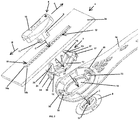
- the adjustment device 4 is shown respectively in an exploded view of the components of the device 4 and a sectional view of the device 4 where its components are assembled.
- the adjustment device 4 makes it possible to adjust the position of a first part 3a with respect to a second part 2a.
- a setting device 4 is particularly suitable for protective helmets 1, and in this case, the first piece 3a is mounted on the neckband 3 of the helmet 1, and the second piece 2a is mounted on the cap 2 of the helmet 1 .
- the adjusting device 4 comprises the adjusting knob 6, a locking element 7, and a retaining washer 8.
- the adjusting knob 6 comprises a foot 9 extended at a first end of a head 10 for a grip of the button 6, and extended to a second end opposite by a base 11.
- the adjusting knob 6 is mounted to move in translation within a groove 12 provided in the second part 2a.
- the groove 12 forms an elongated through hole and the foot 9 of the adjusting knob 6 can slide in the groove 12.
- the groove 12 can be rectilinear or curved.
- the groove 12 preferably has a longitudinal shape within which the adjusting knob 6 moves in translation.
- the groove 12 serves to guide the displacement in translation of the adjustment knob 6.
- the button setting 6 can translate along the groove 12 in two possible translation directions A, B possible.
- the locking element 7, the first part 3a and the retaining washer 8 respectively comprise three through-holes 13 to 15, to allow a passage of the foot 9 of the adjustment knob 10.
- the locking element 7 is located between the first and second parts 3a, 2a, the second part 2a is located between the head 10 of the adjusting knob and the locking element 7, the foot 9 of the button 6 passes, consecutively, the groove 12, the through hole 13 of the blocking element 7, the through hole 14 of the first part 3a, then the through orifice 15 of the retaining washer 8.
- the retaining washer 8 makes it possible to maintain the components of the adjusting device 4 together.
- the adjusting knob 6, the locking element 7, the first part 3a and the retaining washer 8 are integral with each other, and can be translated together relative to the second part 2a.
- the foot 9 of the adjusting knob 6 is inserted along a normal axis C to the groove 12, and the retaining washer 8 is placed to hold the assembly together.
- the locking element 7 makes it possible to prevent the first part 3a from translating along the groove 12 when the adjustment knob 6 is in an initial position.
- the adjustment knob 6 in the initial position.
- the blocking element 7 blocks the first part 3a and prevents it from translating. There is therefore no possible adjustment of the first part 3a relative to the second part 2a.
- the locking element 7 is in a locked position in which the locking element 7 prevents the first part 3a from translating along the groove 12.
- the button 6 when the user translates the button 6, according to the first or the second translation direction A, B, the button 6 cooperates with the locking element 7 to bring the locking element 7 into an unlocked position and to translate the first part 3a relative to the second 2a along the groove 12 In the unlocked position, the locking element 7 allows the first part 3a to translate along the groove 12.
- the second piece 2a may comprise position indexing means 16 for holding the second piece 2a in a chosen position.
- the indexing means 16 are mounted on the cap 2.
- the indexing means 16 are formed on the cap 2, by molding.
- the indexing means 16 are oriented towards the first part 3a, that is to say that they are located opposite the first part 3a.
- the indexing means 16 are located on the inner edge of the cap 2.
- the indexing means 16 may comprise at least one rack 16a, 16b.
- Each rack 16a, 16b comprises a series of notches and a series of notches, and wherein two successive notches are separated from each other by a notch.
- the indexing means 16 comprise two racks 16a, 16b parallel to each other and separated from one another by the groove 12.
- the locking element 7 comprises at least one lug 17 to 20 configured to engage in the indexing means 16 in order to lock in position the first part 3a, that is to say to prevent the first piece 3a of translate along the groove 12 when the adjustment knob 6 is in its initial position and does not translate.
- at least one lug 17 to 20 engages in a notch of at least one rack 16a, 16b.
- the locking element 7 comprises two lugs 17, 20 located opposite one another along an axis parallel to the groove 12. In this case, in the position locked the locking element 7, the first lug 17 prevents a translation of the first part 3a in the first direction A, and the second lug 19 prevents a translation of the first part 3a in the second direction B.
- the locking element 7 comprises a first pair of lugs 17, 18 intended to engage respectively in the notches of the two racks 16a, 16b to prevent a translation of the first part 3a in the first direction A, and a second pair of lugs 19, 20 intended to engage respectively in the notches of the two racks 16a, 16b to prevent translation of the first part 3a in the second direction B.
- the adjustment button 6 When the adjustment button 6 translates along the groove 12, it cooperates with the locking element 7 so as to disengage the lugs 17, 18 of the first pair of notches where they are to unlock the first part 3a. Thus, the adjustment knob 6 brings the locking element 7 into the unlocked position and can translate the first part 3a along the groove 12.
- the locking element 7 is resilient to disengage by deformation the lugs 17 to 20 of the indexing means 16 when the adjustment knob 6 translates along the groove 12.
- the locking element 7 may comprise two resilient blades 21, 22 to make the locking element 7 deformable.
- the blades 21, 22 are deformed to allow disengagement of the lugs 17 to 20 of the indexing means 16, and to bring the lugs into the following notches after passage of the notches which blocked them.
- the blades 21, 22 are located on either side of the through orifice 13 of the locking element 7.
- the adjusting element 7 may further comprise at least one unlocking arm 23, 24.
- the adjusting element 7 comprises a lug 17, or a pair of lugs 17, 18, it comprises an unlocking arm 23 located at the lugs 17, 18, preferably situated between the two lugs 17, 18.
- the adjusting element 7 comprises two opposite lugs 17, 19 located on the same axis parallel to the groove 12, or two pairs of pins 17 to 20, it comprises two unlocking arms 23, 24.
- a first arm 23 hangs against a main abutment 25 located on the first part 3a.
- the first part 3a may also comprise a secondary abutment 26 to allow support of the second arm 24.
- Each unlocking arm 23, 24 is intended to deform the locking element 7 when the adjusting knob 6 translate in a translation direction A , B.
- the support of an unlocking arm 23, 24 against a stop 25, 26 is by an extension of the arm which forms a bearing head 27, 28 coming into contact with a stop 24, 25 of the first piece 3a. Since the bearing head 27 is located against the stop 25, the unlocking arm 23 rotates about an axis perpendicular to the translation direction A of the adjusting knob 6 and perpendicular to the normal axis C to the groove 12. The rotation of the unlocking arm 23 causes a deformation of the resilient blades 21, 22 which tend to flatten. The deformation of the blades 21, 22 then disengages the lugs 17, 18 of the racks 16b, 16a.
- an unlocking arm 23, 24 transmits the force exerted by the adjusting knob 6 along the axis of the groove 12, in a force on the lugs along an axis normal to the groove 12, in order to disengage the lugs from the notches where they were.
- the locking element 7 is brought into the unlocked position when the lugs are disengaged.
- only the adjustment button 6 translate with respect to the first and second parts 3a, 2a.
- the translation of the adjusting knob 6 to disengage the lugs is also noted first translation.
- the first translation is performed when the pressure force exerted increases and remains below a threshold. Then, the translation of the adjusting knob 6 continues, extending the force exerted on the unlocking arm, the lugs pass the notches that held them in the notches, and the first piece 3a translate, with the adjustment knob 6 and in the same direction, relative to the second part 2a along the groove 12.
- the translation of the adjusting knob 6 allowing the lugs to pass the notches is also noted second translation.
- the second translation is performed when the pressure force exerted is greater than the aforementioned threshold. In other words, during the second translation, an unlocking arm pushes the abutment, against which it is supported, and thus pushes the first part 3a in the same direction as that of the adjustment knob 6.
- the adjustment knob 6 comprises at least one recess 30, 31 for accommodating an unlocking arm 23, 24.
- the adjustment knob 6 comprises two recesses 30, 31 for respectively receiving the two unlocking arms 23 , 24. These recesses 30, 31 make it possible to create a free space for the displacement of the adjustment knob 6 with respect to an unlocking arm 23, 24 when the adjustment knob 6 exerts pressure on the other unlocking arm 23, 24, and vice versa.
- the lugs 17 to 20 disengaged pass the notches and are housed in the following notches, by the restoring force of the resilient blades 21, 22.
- the opposite lugs 19, 20 also pass the notches that held them with a tilt of the lugs.
- the locking element 7 comprises pins 17 to 20 extending in two directions D, E respectively inclined relative to two normal axes C1, C2 to the groove 12.
- the directions D , E lugs are inclined in two opposite directions A, B.
- the adjustment device 4 thus makes it possible to disengage the lugs 17, 18 of the first pair by moving the adjustment knob 6 in the first direction of movement A, and the lugs 19, 20 of the second pair pass the notches thanks to their inclination.
- the adjustment button 6 translates in the opposite direction B, the lugs 19, 20 of the second pair are disengaged from the racks 16b, 16a, and the lugs 17, 18 of the first pair pass the notches thanks to their inclination.
- the lugs 17, 18 of the first pair may have an inclination different from that of the lugs 19, 20 of the second pair, in particular to make more difficult one of the directions A, B of translation of the adjusting knob 6 .
- the adjusting device 4 also operates with a single unlocking arm and a single lug (or two lugs) that is disengaged in one direction or the other by exerting a force on one side or the other of the arm unlocking, using the adjustment knob 6 that is translated in a direction A or the other B. Any change in setting emits a click sound, by the lugs 17 to 20, following the movement of the element blocking 7.
- each head 27, 28 of the unlocking arms 23, 24 can comprise a rounded tongue 34 which cooperates with slots provided in the abutments 25, 26, so as to adjust the angular position of the first part 3a.
- the adjustment of the position of the neckband 3 is carried out by translating the adjustment knob 6. More particularly, when the protective helmet 1 comprises two adjustment devices 4, the user, with both hands, moves the adjustment knobs in translation, towards the front of the helmet 1 to tighten the helmet 1 on its neck, or towards the back of the helmet 1 to loosen it. The lugs disengage the notches to release the ends EX1, EX2 of the neckband 3. Then, the lug of each device 4 passes a notch and engages again in the next notch, again ensuring the locking of the adjustment neckband in the chosen position. The user moves the adjustment button of a device 1 in translation in the groove 12 to the touch of the neckband against the neck of the user.
- the length of the neckband remains constant during the adjustment, while the point of attachment is varied thanks to the indexing means 16 located on the inner wall of the cap 2.
Description
L'invention est relative à un dispositif de réglage de la position d'une première pièce par rapport à une deuxième pièce, et concerne plus particulièrement les casques de protection comprenant un tel dispositif.The invention relates to a device for adjusting the position of a first piece relative to a second piece, and more particularly relates to the protective helmets comprising such a device.
On peut citer la demande de brevet européen
On peut citer la demande de brevet britannique
Un objet de l'invention consiste à palier ces inconvénients, et plus particulièrement à fournir un dispositif de réglage qui soit efficace et simple à utiliser.An object of the invention is to overcome these disadvantages, and more particularly to provide a control device that is efficient and simple to use.
Un autre objet de l'invention consiste à fournir un casque de protection équipé d'un tel dispositif de réglage.Another object of the invention is to provide a protective helmet equipped with such an adjustment device.
Selon un aspect de l'invention, il est proposé un dispositif de réglage de la position d'une première pièce par rapport à une deuxième pièce, comprenant :
- un bouton de réglage monté mobile en translation au sein d'une rainure prévue dans la deuxième pièce, et
- un élément de blocage ayant une position verrouillée dans laquelle l'élément de blocage empêche la première pièce de translater le long de la rainure, et une position déverrouillée dans laquelle l'élément de blocage permet à la première pièce de translater le long de la rainure.
- an adjustment knob movably mounted in translation within a groove provided in the second piece, and
- a locking member having a locked position in which the locking member prevents the first piece from translating along the groove, and an unlocked position in which the locking member allows the first piece to translate along the groove .
Le bouton de réglage est configuré pour translater le long de la rainure pour amener l'élément de blocage dans la position déverrouillée et pour translater la première pièce le long de la rainure.The adjustment knob is configured to translate along the groove to move the locking member into the unlocked position and to translate the first piece along the groove.
Ainsi on facilite l'utilisation du bouton de réglage car il suffit de déplacer le bouton de réglage selon une direction choisie de manière à déplacer la pièce dans la direction choisie. Il n'est plus nécessaire d'appuyer sur un bouton de déverrouillage pour débloquer la pièce à déplacer.Thus it facilitates the use of the adjustment knob because it is sufficient to move the adjustment knob in a chosen direction so as to move the piece in the chosen direction. It is no longer necessary to press an unlock button to unlock the part to be moved.
La deuxième pièce comporte des moyens d'indexage de position, l'élément de blocage comporte au moins un ergot s'engageant dans les moyens d'indexage lorsque l'élément de blocage est dans la position verrouillée, et le bouton de réglage désengage ledit au moins un ergot des moyens d'indexation lorsque le bouton de réglage translate le long de la rainure.The second piece comprises position indexing means, the locking element comprises at least one lug engaging in the indexing means when the locking element is in the locked position, and the adjustment button disengages said at least one lug of the indexing means when the adjustment button translates along the groove.
L'élément de blocage peut être élastique pour désengager par déformation ledit au moins un ergot des moyens d'indexage lorsque le bouton de réglage translate le long de la rainure.The locking member may be resilient to disengage by deforming said at least one lug of the indexing means when the adjustment button translates along the groove.
L'élément de blocage peut comporter au moins un bras de déverrouillage prenant appui contre au moins une butée de la première pièce, le bouton de réglage exerçant une force de pression sur ledit au moins un bras de déverrouillage pour désengager ledit au moins un ergot des moyens d'indexation lorsque le bouton de réglage translate le long de la rainure.The locking element may comprise at least one unlocking arm bearing against at least one stop of the first piece, the adjusting knob exerting a pressing force on said at least one unlocking arm to disengage said at least one of the pins. indexing means when the adjustment button translates along the groove.
L'élément de blocage peut en outre comporter deux ergots s'étendant selon deux directions inclinées respectivement par rapport à deux axes normaux à la rainure.The locking element may further comprise two lugs extending in two directions respectively inclined relative to two normal axes to the groove.
L'élément de blocage peut également comporter deux bras de déverrouillage prenant appui contre respectivement deux butées de la première pièce.The locking element may also comprise two unlocking arms bearing against respectively two stops of the first part.
Le bouton de réglage peut translater le long de la rainure en exerçant une force de pression sur l'élément de blocage, et l'élément de blocage est amené dans la position déverrouillée lorsque la force de pression exercée augmente et reste inférieure à un seuil, et le bouton de réglage translate la première pièce le long de la rainure lorsque la force de pression exercée est supérieure au seuil.The adjustment knob can translate along the groove by exerting a pressing force on the locking element, and the locking element is brought into the unlocked position when the exerted pressure force increases and remains below a threshold, and the adjustment button translates the first piece along the groove when the pressure force exerted is greater than the threshold.
Selon un autre aspect de l'invention, il est proposé un casque de protection comprenant une calotte, un serre-nuque et un dispositif de réglage de la position d'une première pièce par rapport à une deuxième pièce tel que défini ci-avant, dans lequel la première pièce est montée sur le serre-nuque et la deuxième pièce est montée sur la calotte.According to another aspect of the invention, there is provided a protective helmet comprising a cap, a neckband and a device for adjusting the position of a first piece relative to a second piece as defined above, wherein the first piece is mounted on the neckband and the second piece is mounted on the cap.
D'autres avantages et caractéristiques ressortiront plus clairement de la description qui va suivre de modes particuliers de réalisation de l'invention donnés à titre d'exemples non limitatifs et représentés aux dessins annexés, dans lesquels :
- La
figure 1 , illustre schématiquement une vue en perspective d'un mode de réalisation d'un casque de protection muni d'un dispositif de réglage selon l'invention ; - la
figure 2 , illustre schématiquement une vue éclatée en perspective d'un autre mode de réalisation d'un dispositif de réglage selon l'invention ; et - la
figure 3 , illustre de façon schématique une vue en coupe du dispositif de réglage dont les composants sont assemblés.
- The
figure 1 schematically illustrates a perspective view of an embodiment of a protective helmet provided with an adjusting device according to the invention; - the
figure 2 schematically illustrates an exploded perspective view of another embodiment of an adjusting device according to the invention; and - the
figure 3 , schematically illustrates a sectional view of the adjusting device whose components are assembled.
Sur la
La position du serre-nuque 3 est ajustable par le dispositif de réglage 4 qui comporte un bouton de réglage 6 accessible depuis l'extérieur de la calotte 5. Le casque 1 peut comporter un seul dispositif de réglage 4 pour régler la position d'une extrémité du serre-nuque 3. Préférentiellement, le casque de protection 1 comporte deux dispositifs de réglage situés sur les côtés latéraux opposés de la calotte 2.The position of the neckband 3 is adjustable by the adjusting
Sur les
Le dispositif de réglage 4 comporte le bouton de réglage 6, un élément de blocage 7, et une rondelle de retenue 8. Le bouton de réglage 6 comporte un pied 9 prolongé à une première extrémité d'une tête 10 pour une prise en main du bouton 6, et prolongé à une deuxième extrémité opposée par une embase 11. Le bouton de réglage 6 est monté mobile en translation au sein d'une rainure 12 prévue dans la deuxième pièce 2a. La rainure 12 forme un orifice allongé traversant et le pied 9 du bouton de réglage 6 peut coulisser dans la rainure 12. La rainure 12 peut être rectiligne ou incurvée. La rainure 12 a de préférence une forme longitudinale à l'intérieur de laquelle se déplace en translation le bouton de réglage 6. La rainure 12 sert de guidage du déplacement en translation du bouton de réglage 6. Ainsi, le bouton de réglage 6 peut translater le long de la rainure 12 selon deux directions de translation opposées A, B possibles.The adjusting
L'élément de blocage 7, la première pièce 3a et la rondelle de retenue 8 comportent respectivement trois orifices traversant 13 à 15, pour permettre un passage du pied 9 du bouton de réglage 10. Lorsque les composants du dispositifs de réglage 4 sont assemblés, l'élément de blocage 7 est situé entre les première et deuxième pièces 3a, 2a, la deuxième pièce 2a est située entre la tête 10 du bouton de réglage et l'élément de blocage 7, le pied 9 du bouton 6 traverse, consécutivement, la rainure 12, l'orifice traversant 13 de l'élément de blocage 7, l'orifice traversant 14 de la première pièce 3a, puis l'orifice traversant 15 de la rondelle de retenue 8. La rondelle de retenue 8 permet de maintenir les composants du dispositif de réglage 4 ensemble. Ainsi, le bouton de réglage 6, l'élément de blocage 7, la première pièce 3a et la rondelle de retenue 8 sont solidaires entre eux, et peuvent être translatés ensemble par rapport à la deuxième pièce 2a. Lors de l'assemblage des composants, on insère le pied 9 du bouton de réglage 6 selon un axe normal C à la rainure 12, puis on place la rondelle de retenue 8 pour maintenir l'ensemble.The
L'élément de blocage 7 permet d'empêcher la première pièce 3a de translater le long de la rainure 12 lorsque le bouton de réglage 6 est dans une position initiale. On a illustré sur la
Par exemple, la deuxième pièce 2a peut comporter des moyens d'indexage 16 de position destinés à maintenir la deuxième pièce 2a dans une position choisie. Sur la
L'élément de blocage 7 comporte au moins un ergot 17 à 20 configuré pour s'engager dans les moyens d'indexage 16 afin de bloquer en position la première pièce 3a, c'est-à-dire pour empêcher la première pièce 3a de translater le long de la rainure 12 lorsque le bouton de réglage 6 est dans sa position initiale et qu'il ne translate pas. Dans la position verrouillée de l'élément de blocage 7, au moins un ergot 17 à 20 s'engage dans une encoche d'au moins une crémaillère 16a, 16b. Selon une variante, l'élément de blocage 7 comporte deux ergots 17, 20 situés à l'opposé l'un de l'autre le long d'un axe parallèle à la rainure 12. Dans ce cas, dans la position verrouillée de l'élément de blocage 7, le premier ergot 17 empêche une translation de la première pièce 3a selon la première direction A, et le deuxième ergot 19 empêche une translation de la première pièce 3a selon la deuxième direction B. Avantageusement, lorsque les moyens d'indexage 16 comportent deux crémaillères 16a, 16b, l'élément de blocage 7 comporte une première paire d'ergots 17, 18 destinés à s'engager respectivement dans les encoches des deux crémaillères 16a, 16b pour empêcher une translation de la première pièce 3a selon la première direction A, et une deuxième paire d'ergots 19, 20 destinés à s'engager respectivement dans les encoches des deux crémaillères 16a, 16b pour empêcher une translation de la première pièce 3a selon la deuxième direction B.The locking
Lorsque le bouton de réglage 6 translate le long de la rainure 12, il coopère avec l'élément de blocage 7 de manière à désengager les ergots 17, 18 de la première paire des encoches où ils se trouvent afin de débloquer la première pièce 3a. Ainsi, le bouton de réglage 6 amène l'élément de blocage 7 dans la position déverrouillée et peut translater la première pièce 3a le long de la rainure 12.When the
De manière générale, l'élément de blocage 7 est élastique pour désengager par déformation les ergots 17 à 20 des moyens d'indexage 16 lorsque le bouton de réglage 6 translate le long de la rainure 12. Par exemple, l'élément de blocage 7 peut comporter deux lames élastiques 21, 22 pour rendre l'élément de blocage 7 déformable. Les lames 21, 22 se déforment pour permettre un désengagement des ergots 17 à 20 des moyens d'indexage 16, et pour ramener les ergots dans les encoches suivantes après passage des crans qui les bloquaient. Les lames 21, 22 sont situées de part et d'autre de l'orifice traversant 13 de l'élément de blocage 7.In general, the locking
L'élément de réglage 7 peut en outre comporter au moins un bras de déverrouillage 23, 24. Lorsque l'élément de réglage 7 comporte un ergot 17, ou une paire d'ergots 17, 18, il comporte un bras de déverrouillage 23 situé au niveau des ergots 17, 18, de préférence situé entre les deux ergots 17, 18. Lorsque l'élément de réglage 7 comporte deux ergots opposés 17, 19 situés sur le même axe parallèle à la rainure 12, ou deux paires d'ergots 17 à 20, il comporte deux bras de déverrouillage 23, 24. Un premier bras 23 pend appui contre une butée principale 25 située sur la première pièce 3a. La première pièce 3a peut également comprendre une butée secondaire 26 pour permettre un appui du deuxième bras 24. Chaque bras de déverrouillage 23, 24 est destiné à déformer l'élément de blocage 7 lorsque le bouton de réglage 6 translate selon une direction de translation A, B. En particulier, lorsque le bouton translate selon la première direction A, il exerce une force de pression sur le premier bras 23 pour désengager la première paire d'ergots 17, 18 des moyens d'indexation 16. Lorsque le bouton de réglage 6 translate selon la deuxième direction B, il exerce une force de pression sur le deuxième bras 24 pour désengager la deuxième paire d'ergots 19, 20 des moyens d'indexation 16. En d'autres termes, lorsque le bouton de réglage 6 translate selon une direction A, B, il pousse le bras de déverrouillage 23, 24 qui prend appui sur une butée 25, 26 de la première pièce 3a pour translater les ergots 17 à 20 en direction de la première pièce 3a selon un axe normal à la rainure 12. L'appui d'un bras de déverrouillage 23, 24 contre une butée 25, 26 se fait par un prolongement du bras qui forme une tête d'appui 27, 28 venant au contact d'une butée 24, 25 de la première pièce 3a. Etant donné que la tête d'appui 27 est située contre la butée 25, le bras de déverrouillage 23 effectue une rotation selon un axe perpendiculaire à la direction de translation A du bouton de réglage 6 et perpendiculaire à l'axe normal C à la rainure 12. La rotation du bras de déverrouillage 23 entraîne une déformation des lames élastiques 21, 22 qui ont tendance à s'aplatir. La déformation des lames 21, 22 désengage alors les ergots 17, 18 des crémaillères 16b, 16a. Ainsi, un bras de déverrouillage 23, 24 transmet la force exercée par le bouton de réglage 6 selon l'axe de la rainure 12, en une force sur les ergots selon un axe normal à la rainure 12, afin de désengager les ergots des encoches où ils se trouvaient. L'élément de blocage 7 est amené dans la position déverrouillée lorsque les ergots sont désengagés. Par ailleurs, lorsque les ergots se désengagent des encoches, seul le bouton de réglage 6 translate par rapport aux première et deuxième pièces 3a, 2a. Il existe en outre un espace libre 29 entre la rondelle de retenue 8 et les butées 25, 26 pour permettre la translation du bouton de réglage 6 afin de désengager les ergots. La translation du bouton de réglage 6 permettant de désengager les ergots est également notée première translation. Plus particulièrement, la première translation est réalisée lorsque la force de pression exercée augmente et reste inférieure à un seuil. Puis, la translation du bouton de réglage 6 se poursuit, prolongeant la force exercée sur le bras de déverrouillage, les ergots passent les crans qui les retenaient dans les encoches, et la première pièce 3a translate, avec le bouton de réglage 6 et dans la même direction, par rapport à la deuxième pièce 2a le long de la rainure 12. La translation du bouton de réglage 6 permettant aux ergots de passer les crans est également notée deuxième translation. La deuxième translation est réalisée lorsque la force de pression exercée est supérieure au seuil précité. En d'autres termes lors de la deuxième translation, un bras de déverrouillage pousse la butée, contre laquelle il est en appui, et pousse donc la première pièce 3a dans la même direction que celle du bouton de réglage 6.The adjusting
On peut noter que le bouton de réglage 6 comporte au moins un évidement 30, 31 pour loger un bras de déverrouillage 23, 24. De préférence, le bouton de réglage 6 comporte deux évidements 30, 31 pour recevoir respectivement les deux bras de déverrouillage 23, 24. Ces évidements 30, 31 permettent de créer un espace libre pour le déplacement du bouton de réglage 6 par rapport à un bras de déverrouillage 23, 24 lorsque le bouton de réglage 6 exerce une pression sur l'autre bras de déverrouillage 23, 24, et inversement.It may be noted that the
Les ergots 17 à 20 désengagés passent les crans et viennent se loger dans les encoches suivantes, par la force de rappel des lames élastiques 21, 22. En particulier, lorsque la première paire d'ergots 17, 18 passent les crans, les ergots opposés 19, 20 passent également les crans qui les retenaient grâce à une inclinaison des ergots. Dans un mode de réalisation préféré, l'élément de blocage 7 comporte des ergots 17 à 20 s'étendant selon deux directions D, E respectivement inclinées par rapport à deux axes normaux C1, C2 à la rainure 12. En outre, les directions D, E des ergots sont inclinées selon deux sens opposés A, B. Le dispositif de réglage 4 permet ainsi, de désengager les ergots 17, 18 de la première paire en déplaçant le bouton de réglage 6 selon le premier sens de déplacement A, et les ergots 19, 20 de la deuxième paire passent les crans grâce à leur inclinaison. Lorsque le bouton de réglage 6 translate dans le sens inverse B, les ergots 19, 20 de la deuxième paire sont désengagés des crémaillères 16b, 16a, et les ergots 17, 18 de la première paire passent les crans grâce à leur inclinaison. En variante, les ergots 17, 18 de la première paire peuvent avoir une inclinaison différente de celle des ergots 19, 20 de la deuxième paire, afin notamment de rendre plus difficile l'une des directions A, B de translation du bouton de réglage 6.The
Le dispositif de réglage 4 fonctionne également avec un seul bras de déverrouillage et un seul ergot (ou deux ergots) que l'on désengage dans un sens ou dans l'autre en exerçant une force d'un côté ou de l'autre du bras de déverrouillage, à l'aide du bouton de réglage 6 que l'on translate selon une direction A ou l'autre B. Tout changement de réglage émet un clic sonore, par les ergots 17 à 20, suite au déplacement de l'élément de blocage 7.The adjusting
En variante, les têtes 27, 28 des bras de déverrouillage sont introduits dans des lumières traversantes 32, 33 prévues dans la première pièce 3a. Ainsi, la première pièce 34 peut être mobile en rotation autour de l'axe normal C à la rainure 12 pour incliner la première pièce 3a par rapport à la deuxième pièce 2a. De préférence, chaque tête 27, 28 des bras de déverrouillage 23, 24 peut comprendre une languette arrondie 34 qui coopère avec des fentes prévues dans les butées 25, 26, de façon à pouvoir régler la position angulaire de la première pièce 3a.Alternatively, the
Le réglage de la position du serre-nuque 3 s'effectue en translatant le bouton de réglage 6. Plus particulièrement, lorsque le casque de protection 1 comporte deux dispositifs de réglage 4, l'utilisateur, à l'aide de ses deux mains, déplace en translation les boutons de réglage, soit vers l'avant du casque1 pour serrer le casque 1 sur sa nuque, soit vers l'arrière du casque 1 pour le desserrer. Les ergots se désengagent des encoches pour libérer les extrémités EX1, EX2 du serre-nuque 3. Puis, l'ergot de chaque dispositif 4 passe un cran et s'engage à nouveau dans l'encoche suivante, assurant à nouveau le blocage du réglage du serre-nuque dans la position choisie. L'utilisateur déplace le bouton de réglage d'un dispositif 1 en translation dans la rainure 12 jusqu'au contact du serre-nuque contre la nuque de l'utilisateur.The adjustment of the position of the neckband 3 is carried out by translating the
La longueur du serre-nuque reste constante durant le réglage, tandis qu'on fait varier son point d'attache grâce aux moyens d'indexage 16 situés sur la paroi interne de la calotte 2.The length of the neckband remains constant during the adjustment, while the point of attachment is varied thanks to the indexing means 16 located on the inner wall of the
Claims (7)
- Device for adjusting the position of a first part (3a) relative to a second part (2a), comprising:- an adjustment button (6) mounted movable in translation inside a groove (12) provided in the second part (2a) ; and- a blocking part (7) having a locked position in which the blocking part (7) prevents the first part (3a) from translating along the groove (12), and an unlocked position in which the blocking part (7) enables the first part (3a) to translate along the groove (12),the adjustment button (6) being configured to translate along the groove (12) to move the blocking part (7) to the unlocked position and to translate the first part (3a) along the groove (12), and the second part (2a) comprising position indexing means (16), characterized in that the blocking part (7) comprises at least one spigot (17 to 20) engaging in the position indexing means (16) when the blocking part (7) is in the locked position, and the adjustment button (6) disengages said at least one spigot (17 to 20) from the position indexing means (16) when the adjustment button (6) translates along the groove (12).
- Device according to claim 1, wherein the blocking part (7) is flexible to disengage said at least one spigot (17 to 20) from the position indexing means (16) by deformation when the adjustment button (6) translates along the groove (12).
- Device according to claim 1 or 2, wherein the blocking part (7) comprises at least one unlatching arm (23, 24) pressing against at least one stop (25, 26) of the first part (3a), the adjustment button (6) exerting a pressure force on said at least one unlatching arm (23, 24) to disengage said at least one spigot (17 to 20) from the position indexing means (16) when the adjustment button (6) translates along the groove (12).
- Device according to one of claims 1 to 3, wherein the blocking part (7) comprises two spigots (17, 19) extending in two directions respectively inclined relative to two axes normal (C1, C2) to the groove (12).
- Device according to claim 3 or 4, wherein the blocking part (7) comprises two unlatching arms (23, 24) respectively pressing against two stops (25, 26) of the first part (3a).
- Device according to one of claims 1 to 5, wherein the adjustment button (6) is configured to translate along the groove (12) exerting a pressure force on the blocking part (7), and the blocking part (7) is moved to the unlocked position when the exerted pressure force increases and remains lower than a threshold, and the adjustment button (6) is configured to translate the first part (3a) along the groove (12) when the exerted pressure force is higher than the threshold.
- Protective helmet (1) comprising a crown (2), a neckband (3) and device for adjusting (4) the position of a first part (3a) relative to a second part (2a) according to one of claims 1 to 6, wherein the first part (3a) is mounted on the neckband (3) and the second part (2a) is mounted on the crown (2).
Applications Claiming Priority (1)
| Application Number | Priority Date | Filing Date | Title |
|---|---|---|---|
| FR1550112A FR3031277B1 (en) | 2015-01-07 | 2015-01-07 | DEVICE FOR ADJUSTING THE POSITION OF A FIRST PART IN RELATION TO A SECOND PART AND PROTECTIVE HELMET COMPRISING SUCH A DEVICE |
Publications (2)
| Publication Number | Publication Date |
|---|---|
| EP3042580A1 EP3042580A1 (en) | 2016-07-13 |
| EP3042580B1 true EP3042580B1 (en) | 2018-12-05 |
Family
ID=52684542
Family Applications (1)
| Application Number | Title | Priority Date | Filing Date |
|---|---|---|---|
| EP15200154.1A Not-in-force EP3042580B1 (en) | 2015-01-07 | 2015-12-15 | Device for adjusting the position of a first part relative to a second part and protective helmet comprising such a device |
Country Status (3)
| Country | Link |
|---|---|
| US (1) | US9820523B2 (en) |
| EP (1) | EP3042580B1 (en) |
| FR (1) | FR3031277B1 (en) |
Families Citing this family (6)
| Publication number | Priority date | Publication date | Assignee | Title |
|---|---|---|---|---|
| FR3020924B1 (en) * | 2014-05-16 | 2016-06-24 | Zedel | NECKLACE TIGHTENER FOR PROTECTIVE HELMETS |
| FR3031277B1 (en) * | 2015-01-07 | 2017-05-26 | Zedel | DEVICE FOR ADJUSTING THE POSITION OF A FIRST PART IN RELATION TO A SECOND PART AND PROTECTIVE HELMET COMPRISING SUCH A DEVICE |
| US10786031B2 (en) * | 2015-06-24 | 2020-09-29 | Christopher D. Gowen | Helmet assembly |
| US20170238643A1 (en) * | 2016-02-23 | 2017-08-24 | A.C.E. International | Head Gear |
| US10980307B2 (en) * | 2017-08-14 | 2021-04-20 | Thomas M. Stade | Helmet system |
| JP7041050B2 (en) * | 2018-12-20 | 2022-03-23 | 株式会社Shoei | Screen device and helmet |
Family Cites Families (7)
| Publication number | Priority date | Publication date | Assignee | Title |
|---|---|---|---|---|
| US2437748A (en) * | 1945-06-11 | 1948-03-16 | Chicago Eye Shield Company | Adjustable headband construction |
| US3500474A (en) * | 1968-10-08 | 1970-03-17 | Mine Safety Appliances Co | Adjustable headband |
| GB2354928A (en) * | 1999-10-07 | 2001-04-11 | Raleigh Industries Ltd | An adjuster for a helmet |
| TW456189U (en) * | 2000-09-27 | 2001-09-21 | Fang Guo Yun | Band adjustment structure for safety helmet |
| FR2932961B1 (en) | 2008-06-26 | 2010-08-20 | Zedel | AN ADJUSTABLE NECKLAR PROTECTIVE HELMET |
| US20110191946A1 (en) * | 2010-02-11 | 2011-08-11 | Kenneth Fang | Hat band structure |
| FR3031277B1 (en) * | 2015-01-07 | 2017-05-26 | Zedel | DEVICE FOR ADJUSTING THE POSITION OF A FIRST PART IN RELATION TO A SECOND PART AND PROTECTIVE HELMET COMPRISING SUCH A DEVICE |
-
2015
- 2015-01-07 FR FR1550112A patent/FR3031277B1/en not_active Expired - Fee Related
- 2015-12-15 EP EP15200154.1A patent/EP3042580B1/en not_active Not-in-force
-
2016
- 2016-01-07 US US14/990,229 patent/US9820523B2/en not_active Expired - Fee Related
Non-Patent Citations (1)
| Title |
|---|
| None * |
Also Published As
| Publication number | Publication date |
|---|---|
| FR3031277A1 (en) | 2016-07-08 |
| EP3042580A1 (en) | 2016-07-13 |
| FR3031277B1 (en) | 2017-05-26 |
| US9820523B2 (en) | 2017-11-21 |
| US20160192726A1 (en) | 2016-07-07 |
Similar Documents
| Publication | Publication Date | Title |
|---|---|---|
| EP3042580B1 (en) | Device for adjusting the position of a first part relative to a second part and protective helmet comprising such a device | |
| EP3213654B1 (en) | System with retractable pins for attaching a band to a watch | |
| EP1250063B1 (en) | Device for adjusting head band for protective helmet | |
| EP2138061B1 (en) | Safety helmet with improved adjustable napestrap | |
| EP2138062B1 (en) | Safety helmet with napestrap for hair tied back in a ponytail | |
| EP2888967B1 (en) | Bracelet clasp comprising a device for adjusting the useful length of the bracelet | |
| EP2740382B1 (en) | Bracelet clasp comprising a device for adjusting the useful length of the bracelet | |
| EP2725937B1 (en) | Extendable clasp for a bracelet in particular for a watch | |
| WO2008034603A1 (en) | Strap device for securing objects in a suitcase | |
| EP3164767B1 (en) | Watch and band thereof | |
| FR2970446A1 (en) | ATTACHMENT FOR ATTACHING A CARPET TO A CARPET | |
| EP3088970A1 (en) | Watch intended for being mounted on a removable support | |
| EP2888424A1 (en) | Removable attachment device for attaching to longer linear or filiform objects | |
| EP2953816B1 (en) | Headrest for a motor vehicle seat | |
| EP3756501A1 (en) | Fixing device for a bracelet | |
| EP2740381A1 (en) | Adjustable bracelet clasp | |
| CH700230B1 (en) | bracelet clasp comprising a fine adjustment device of the useful length of the bracelet. | |
| EP2760703B1 (en) | Device for attaching a motor vehicle roof bar and arrangement of roof bars which have been assembled in various configurations using such a device | |
| US20160037881A1 (en) | Earring with latching mechanism | |
| EP3214964B1 (en) | Variable-shape connection device for straps, objects, portions of garments and accessories | |
| CH709021A2 (en) | bracelet clasp comprising a device for adjusting the useful length of the bracelet. | |
| CH712040A2 (en) | Clasp folding for bracelet. | |
| FR3002112A1 (en) | Garden scissor, has adjustment element placed in swiveling manner on handle such that groove is in play with teeth, and angle restriction element that is rotated by helicoid part so as to change maximum cut angle of chisel element | |
| WO2020053323A1 (en) | Device for removably mounting an airbag module | |
| EP2960406A1 (en) | Device for opening and closing an article, especially made of leather, and article comprising such a device |
Legal Events
| Date | Code | Title | Description |
|---|---|---|---|
| PUAI | Public reference made under article 153(3) epc to a published international application that has entered the european phase |
Free format text: ORIGINAL CODE: 0009012 |
|
| AK | Designated contracting states |
Kind code of ref document: A1 Designated state(s): AL AT BE BG CH CY CZ DE DK EE ES FI FR GB GR HR HU IE IS IT LI LT LU LV MC MK MT NL NO PL PT RO RS SE SI SK SM TR |
|
| AX | Request for extension of the european patent |
Extension state: BA ME |
|
| 17P | Request for examination filed |
Effective date: 20170112 |
|
| RBV | Designated contracting states (corrected) |
Designated state(s): AL AT BE BG CH CY CZ DE DK EE ES FI FR GB GR HR HU IE IS IT LI LT LU LV MC MK MT NL NO PL PT RO RS SE SI SK SM TR |
|
| GRAP | Despatch of communication of intention to grant a patent |
Free format text: ORIGINAL CODE: EPIDOSNIGR1 |
|
| INTG | Intention to grant announced |
Effective date: 20180306 |
|
| GRAS | Grant fee paid |
Free format text: ORIGINAL CODE: EPIDOSNIGR3 |
|
| GRAA | (expected) grant |
Free format text: ORIGINAL CODE: 0009210 |
|
| AK | Designated contracting states |
Kind code of ref document: B1 Designated state(s): AL AT BE BG CH CY CZ DE DK EE ES FI FR GB GR HR HU IE IS IT LI LT LU LV MC MK MT NL NO PL PT RO RS SE SI SK SM TR |
|
| REG | Reference to a national code |
Ref country code: GB Ref legal event code: FG4D Free format text: NOT ENGLISH |
|
| REG | Reference to a national code |
Ref country code: CH Ref legal event code: EP |
|
| REG | Reference to a national code |
Ref country code: AT Ref legal event code: REF Ref document number: 1071934 Country of ref document: AT Kind code of ref document: T Effective date: 20181215 |
|
| REG | Reference to a national code |
Ref country code: IE Ref legal event code: FG4D Free format text: LANGUAGE OF EP DOCUMENT: FRENCH |
|
| REG | Reference to a national code |
Ref country code: DE Ref legal event code: R096 Ref document number: 602015020797 Country of ref document: DE |
|
| REG | Reference to a national code |
Ref country code: NL Ref legal event code: MP Effective date: 20181205 |
|
| REG | Reference to a national code |
Ref country code: AT Ref legal event code: MK05 Ref document number: 1071934 Country of ref document: AT Kind code of ref document: T Effective date: 20181205 |
|
| REG | Reference to a national code |
Ref country code: LT Ref legal event code: MG4D |
|
| PG25 | Lapsed in a contracting state [announced via postgrant information from national office to epo] |
Ref country code: ES Free format text: LAPSE BECAUSE OF FAILURE TO SUBMIT A TRANSLATION OF THE DESCRIPTION OR TO PAY THE FEE WITHIN THE PRESCRIBED TIME-LIMIT Effective date: 20181205 Ref country code: LV Free format text: LAPSE BECAUSE OF FAILURE TO SUBMIT A TRANSLATION OF THE DESCRIPTION OR TO PAY THE FEE WITHIN THE PRESCRIBED TIME-LIMIT Effective date: 20181205 Ref country code: FI Free format text: LAPSE BECAUSE OF FAILURE TO SUBMIT A TRANSLATION OF THE DESCRIPTION OR TO PAY THE FEE WITHIN THE PRESCRIBED TIME-LIMIT Effective date: 20181205 Ref country code: BG Free format text: LAPSE BECAUSE OF FAILURE TO SUBMIT A TRANSLATION OF THE DESCRIPTION OR TO PAY THE FEE WITHIN THE PRESCRIBED TIME-LIMIT Effective date: 20190305 Ref country code: HR Free format text: LAPSE BECAUSE OF FAILURE TO SUBMIT A TRANSLATION OF THE DESCRIPTION OR TO PAY THE FEE WITHIN THE PRESCRIBED TIME-LIMIT Effective date: 20181205 Ref country code: AT Free format text: LAPSE BECAUSE OF FAILURE TO SUBMIT A TRANSLATION OF THE DESCRIPTION OR TO PAY THE FEE WITHIN THE PRESCRIBED TIME-LIMIT Effective date: 20181205 Ref country code: LT Free format text: LAPSE BECAUSE OF FAILURE TO SUBMIT A TRANSLATION OF THE DESCRIPTION OR TO PAY THE FEE WITHIN THE PRESCRIBED TIME-LIMIT Effective date: 20181205 Ref country code: NO Free format text: LAPSE BECAUSE OF FAILURE TO SUBMIT A TRANSLATION OF THE DESCRIPTION OR TO PAY THE FEE WITHIN THE PRESCRIBED TIME-LIMIT Effective date: 20190305 |
|
| PG25 | Lapsed in a contracting state [announced via postgrant information from national office to epo] |
Ref country code: SE Free format text: LAPSE BECAUSE OF FAILURE TO SUBMIT A TRANSLATION OF THE DESCRIPTION OR TO PAY THE FEE WITHIN THE PRESCRIBED TIME-LIMIT Effective date: 20181205 Ref country code: RS Free format text: LAPSE BECAUSE OF FAILURE TO SUBMIT A TRANSLATION OF THE DESCRIPTION OR TO PAY THE FEE WITHIN THE PRESCRIBED TIME-LIMIT Effective date: 20181205 Ref country code: GR Free format text: LAPSE BECAUSE OF FAILURE TO SUBMIT A TRANSLATION OF THE DESCRIPTION OR TO PAY THE FEE WITHIN THE PRESCRIBED TIME-LIMIT Effective date: 20190306 Ref country code: AL Free format text: LAPSE BECAUSE OF FAILURE TO SUBMIT A TRANSLATION OF THE DESCRIPTION OR TO PAY THE FEE WITHIN THE PRESCRIBED TIME-LIMIT Effective date: 20181205 |
|
| PG25 | Lapsed in a contracting state [announced via postgrant information from national office to epo] |
Ref country code: NL Free format text: LAPSE BECAUSE OF FAILURE TO SUBMIT A TRANSLATION OF THE DESCRIPTION OR TO PAY THE FEE WITHIN THE PRESCRIBED TIME-LIMIT Effective date: 20181205 |
|
| PG25 | Lapsed in a contracting state [announced via postgrant information from national office to epo] |
Ref country code: CZ Free format text: LAPSE BECAUSE OF FAILURE TO SUBMIT A TRANSLATION OF THE DESCRIPTION OR TO PAY THE FEE WITHIN THE PRESCRIBED TIME-LIMIT Effective date: 20181205 Ref country code: PT Free format text: LAPSE BECAUSE OF FAILURE TO SUBMIT A TRANSLATION OF THE DESCRIPTION OR TO PAY THE FEE WITHIN THE PRESCRIBED TIME-LIMIT Effective date: 20190405 Ref country code: PL Free format text: LAPSE BECAUSE OF FAILURE TO SUBMIT A TRANSLATION OF THE DESCRIPTION OR TO PAY THE FEE WITHIN THE PRESCRIBED TIME-LIMIT Effective date: 20181205 |
|
| REG | Reference to a national code |
Ref country code: CH Ref legal event code: PL |
|
| PG25 | Lapsed in a contracting state [announced via postgrant information from national office to epo] |
Ref country code: IS Free format text: LAPSE BECAUSE OF FAILURE TO SUBMIT A TRANSLATION OF THE DESCRIPTION OR TO PAY THE FEE WITHIN THE PRESCRIBED TIME-LIMIT Effective date: 20190405 Ref country code: SK Free format text: LAPSE BECAUSE OF FAILURE TO SUBMIT A TRANSLATION OF THE DESCRIPTION OR TO PAY THE FEE WITHIN THE PRESCRIBED TIME-LIMIT Effective date: 20181205 Ref country code: SM Free format text: LAPSE BECAUSE OF FAILURE TO SUBMIT A TRANSLATION OF THE DESCRIPTION OR TO PAY THE FEE WITHIN THE PRESCRIBED TIME-LIMIT Effective date: 20181205 Ref country code: EE Free format text: LAPSE BECAUSE OF FAILURE TO SUBMIT A TRANSLATION OF THE DESCRIPTION OR TO PAY THE FEE WITHIN THE PRESCRIBED TIME-LIMIT Effective date: 20181205 Ref country code: LU Free format text: LAPSE BECAUSE OF NON-PAYMENT OF DUE FEES Effective date: 20181215 Ref country code: RO Free format text: LAPSE BECAUSE OF FAILURE TO SUBMIT A TRANSLATION OF THE DESCRIPTION OR TO PAY THE FEE WITHIN THE PRESCRIBED TIME-LIMIT Effective date: 20181205 |
|
| REG | Reference to a national code |
Ref country code: DE Ref legal event code: R097 Ref document number: 602015020797 Country of ref document: DE |
|
| REG | Reference to a national code |
Ref country code: IE Ref legal event code: MM4A |
|
| REG | Reference to a national code |
Ref country code: BE Ref legal event code: MM Effective date: 20181231 |
|
| PLBE | No opposition filed within time limit |
Free format text: ORIGINAL CODE: 0009261 |
|
| STAA | Information on the status of an ep patent application or granted ep patent |
Free format text: STATUS: NO OPPOSITION FILED WITHIN TIME LIMIT |
|
| PG25 | Lapsed in a contracting state [announced via postgrant information from national office to epo] |
Ref country code: IE Free format text: LAPSE BECAUSE OF NON-PAYMENT OF DUE FEES Effective date: 20181215 Ref country code: SI Free format text: LAPSE BECAUSE OF FAILURE TO SUBMIT A TRANSLATION OF THE DESCRIPTION OR TO PAY THE FEE WITHIN THE PRESCRIBED TIME-LIMIT Effective date: 20181205 Ref country code: MC Free format text: LAPSE BECAUSE OF FAILURE TO SUBMIT A TRANSLATION OF THE DESCRIPTION OR TO PAY THE FEE WITHIN THE PRESCRIBED TIME-LIMIT Effective date: 20181205 Ref country code: DK Free format text: LAPSE BECAUSE OF FAILURE TO SUBMIT A TRANSLATION OF THE DESCRIPTION OR TO PAY THE FEE WITHIN THE PRESCRIBED TIME-LIMIT Effective date: 20181205 |
|
| 26N | No opposition filed |
Effective date: 20190906 |
|
| PG25 | Lapsed in a contracting state [announced via postgrant information from national office to epo] |
Ref country code: BE Free format text: LAPSE BECAUSE OF NON-PAYMENT OF DUE FEES Effective date: 20181231 |
|
| PG25 | Lapsed in a contracting state [announced via postgrant information from national office to epo] |
Ref country code: LI Free format text: LAPSE BECAUSE OF NON-PAYMENT OF DUE FEES Effective date: 20181231 Ref country code: CH Free format text: LAPSE BECAUSE OF NON-PAYMENT OF DUE FEES Effective date: 20181231 |
|
| PG25 | Lapsed in a contracting state [announced via postgrant information from national office to epo] |
Ref country code: MT Free format text: LAPSE BECAUSE OF FAILURE TO SUBMIT A TRANSLATION OF THE DESCRIPTION OR TO PAY THE FEE WITHIN THE PRESCRIBED TIME-LIMIT Effective date: 20181205 |
|
| PGFP | Annual fee paid to national office [announced via postgrant information from national office to epo] |
Ref country code: DE Payment date: 20191203 Year of fee payment: 5 |
|
| PGFP | Annual fee paid to national office [announced via postgrant information from national office to epo] |
Ref country code: FR Payment date: 20191115 Year of fee payment: 5 Ref country code: IT Payment date: 20191209 Year of fee payment: 5 |
|
| PG25 | Lapsed in a contracting state [announced via postgrant information from national office to epo] |
Ref country code: TR Free format text: LAPSE BECAUSE OF FAILURE TO SUBMIT A TRANSLATION OF THE DESCRIPTION OR TO PAY THE FEE WITHIN THE PRESCRIBED TIME-LIMIT Effective date: 20181205 |
|
| PGFP | Annual fee paid to national office [announced via postgrant information from national office to epo] |
Ref country code: GB Payment date: 20191213 Year of fee payment: 5 |
|
| PG25 | Lapsed in a contracting state [announced via postgrant information from national office to epo] |
Ref country code: MK Free format text: LAPSE BECAUSE OF NON-PAYMENT OF DUE FEES Effective date: 20181205 Ref country code: CY Free format text: LAPSE BECAUSE OF FAILURE TO SUBMIT A TRANSLATION OF THE DESCRIPTION OR TO PAY THE FEE WITHIN THE PRESCRIBED TIME-LIMIT Effective date: 20181205 Ref country code: HU Free format text: LAPSE BECAUSE OF FAILURE TO SUBMIT A TRANSLATION OF THE DESCRIPTION OR TO PAY THE FEE WITHIN THE PRESCRIBED TIME-LIMIT; INVALID AB INITIO Effective date: 20151215 |
|
| REG | Reference to a national code |
Ref country code: DE Ref legal event code: R119 Ref document number: 602015020797 Country of ref document: DE |
|
| GBPC | Gb: european patent ceased through non-payment of renewal fee |
Effective date: 20201215 |
|
| PG25 | Lapsed in a contracting state [announced via postgrant information from national office to epo] |
Ref country code: FR Free format text: LAPSE BECAUSE OF NON-PAYMENT OF DUE FEES Effective date: 20201231 Ref country code: IT Free format text: LAPSE BECAUSE OF NON-PAYMENT OF DUE FEES Effective date: 20201215 |
|
| PG25 | Lapsed in a contracting state [announced via postgrant information from national office to epo] |
Ref country code: GB Free format text: LAPSE BECAUSE OF NON-PAYMENT OF DUE FEES Effective date: 20201215 Ref country code: DE Free format text: LAPSE BECAUSE OF NON-PAYMENT OF DUE FEES Effective date: 20210701 |