EP3041663B1 - Dispositif de chauffage des bords de l'orifice de remplissage d'un tube - Google Patents
Dispositif de chauffage des bords de l'orifice de remplissage d'un tube Download PDFInfo
- Publication number
- EP3041663B1 EP3041663B1 EP14766106.0A EP14766106A EP3041663B1 EP 3041663 B1 EP3041663 B1 EP 3041663B1 EP 14766106 A EP14766106 A EP 14766106A EP 3041663 B1 EP3041663 B1 EP 3041663B1
- Authority
- EP
- European Patent Office
- Prior art keywords
- hot gas
- duct
- tube body
- heating device
- accordance
- Prior art date
- Legal status (The legal status is an assumption and is not a legal conclusion. Google has not performed a legal analysis and makes no representation as to the accuracy of the status listed.)
- Not-in-force
Links
- 238000010438 heat treatment Methods 0.000 title claims description 32
- 239000007789 gas Substances 0.000 claims description 179
- 239000000112 cooling gas Substances 0.000 claims description 9
- 230000000903 blocking effect Effects 0.000 claims 2
- 238000011156 evaluation Methods 0.000 description 8
- 239000000463 material Substances 0.000 description 7
- 239000003570 air Substances 0.000 description 3
- 239000012080 ambient air Substances 0.000 description 3
- 238000013461 design Methods 0.000 description 3
- 238000011161 development Methods 0.000 description 2
- 238000003780 insertion Methods 0.000 description 2
- 230000037431 insertion Effects 0.000 description 2
- 239000000155 melt Substances 0.000 description 2
- 238000003825 pressing Methods 0.000 description 2
- 238000010276 construction Methods 0.000 description 1
- 239000002826 coolant Substances 0.000 description 1
- -1 for example Substances 0.000 description 1
- 238000000034 method Methods 0.000 description 1
- 238000002156 mixing Methods 0.000 description 1
- 239000000203 mixture Substances 0.000 description 1
- 230000008646 thermal stress Effects 0.000 description 1
Images
Classifications
-
- B—PERFORMING OPERATIONS; TRANSPORTING
- B29—WORKING OF PLASTICS; WORKING OF SUBSTANCES IN A PLASTIC STATE IN GENERAL
- B29C—SHAPING OR JOINING OF PLASTICS; SHAPING OF MATERIAL IN A PLASTIC STATE, NOT OTHERWISE PROVIDED FOR; AFTER-TREATMENT OF THE SHAPED PRODUCTS, e.g. REPAIRING
- B29C65/00—Joining or sealing of preformed parts, e.g. welding of plastics materials; Apparatus therefor
- B29C65/02—Joining or sealing of preformed parts, e.g. welding of plastics materials; Apparatus therefor by heating, with or without pressure
- B29C65/10—Joining or sealing of preformed parts, e.g. welding of plastics materials; Apparatus therefor by heating, with or without pressure using hot gases (e.g. combustion gases) or flames coming in contact with at least one of the parts to be joined
- B29C65/103—Joining or sealing of preformed parts, e.g. welding of plastics materials; Apparatus therefor by heating, with or without pressure using hot gases (e.g. combustion gases) or flames coming in contact with at least one of the parts to be joined direct heating both surfaces to be joined
-
- B—PERFORMING OPERATIONS; TRANSPORTING
- B29—WORKING OF PLASTICS; WORKING OF SUBSTANCES IN A PLASTIC STATE IN GENERAL
- B29C—SHAPING OR JOINING OF PLASTICS; SHAPING OF MATERIAL IN A PLASTIC STATE, NOT OTHERWISE PROVIDED FOR; AFTER-TREATMENT OF THE SHAPED PRODUCTS, e.g. REPAIRING
- B29C35/00—Heating, cooling or curing, e.g. crosslinking or vulcanising; Apparatus therefor
- B29C35/02—Heating or curing, e.g. crosslinking or vulcanizing during moulding, e.g. in a mould
- B29C35/04—Heating or curing, e.g. crosslinking or vulcanizing during moulding, e.g. in a mould using liquids, gas or steam
- B29C35/045—Heating or curing, e.g. crosslinking or vulcanizing during moulding, e.g. in a mould using liquids, gas or steam using gas or flames
-
- B—PERFORMING OPERATIONS; TRANSPORTING
- B29—WORKING OF PLASTICS; WORKING OF SUBSTANCES IN A PLASTIC STATE IN GENERAL
- B29B—PREPARATION OR PRETREATMENT OF THE MATERIAL TO BE SHAPED; MAKING GRANULES OR PREFORMS; RECOVERY OF PLASTICS OR OTHER CONSTITUENTS OF WASTE MATERIAL CONTAINING PLASTICS
- B29B13/00—Conditioning or physical treatment of the material to be shaped
- B29B13/02—Conditioning or physical treatment of the material to be shaped by heating
- B29B13/023—Half-products, e.g. films, plates
- B29B13/024—Hollow bodies, e.g. tubes or profiles
- B29B13/025—Tube ends
-
- B—PERFORMING OPERATIONS; TRANSPORTING
- B29—WORKING OF PLASTICS; WORKING OF SUBSTANCES IN A PLASTIC STATE IN GENERAL
- B29C—SHAPING OR JOINING OF PLASTICS; SHAPING OF MATERIAL IN A PLASTIC STATE, NOT OTHERWISE PROVIDED FOR; AFTER-TREATMENT OF THE SHAPED PRODUCTS, e.g. REPAIRING
- B29C57/00—Shaping of tube ends, e.g. flanging, belling or closing; Apparatus therefor, e.g. collapsible mandrels
- B29C57/10—Closing
-
- B—PERFORMING OPERATIONS; TRANSPORTING
- B29—WORKING OF PLASTICS; WORKING OF SUBSTANCES IN A PLASTIC STATE IN GENERAL
- B29C—SHAPING OR JOINING OF PLASTICS; SHAPING OF MATERIAL IN A PLASTIC STATE, NOT OTHERWISE PROVIDED FOR; AFTER-TREATMENT OF THE SHAPED PRODUCTS, e.g. REPAIRING
- B29C66/00—General aspects of processes or apparatus for joining preformed parts
- B29C66/40—General aspects of joining substantially flat articles, e.g. plates, sheets or web-like materials; Making flat seams in tubular or hollow articles; Joining single elements to substantially flat surfaces
- B29C66/41—Joining substantially flat articles ; Making flat seams in tubular or hollow articles
- B29C66/43—Joining a relatively small portion of the surface of said articles
- B29C66/431—Joining the articles to themselves
- B29C66/4312—Joining the articles to themselves for making flat seams in tubular or hollow articles, e.g. transversal seams
- B29C66/43121—Closing the ends of tubular or hollow single articles, e.g. closing the ends of bags
- B29C66/43123—Closing the ends of squeeze tubes, e.g. for toothpaste or cosmetics
-
- B—PERFORMING OPERATIONS; TRANSPORTING
- B29—WORKING OF PLASTICS; WORKING OF SUBSTANCES IN A PLASTIC STATE IN GENERAL
- B29C—SHAPING OR JOINING OF PLASTICS; SHAPING OF MATERIAL IN A PLASTIC STATE, NOT OTHERWISE PROVIDED FOR; AFTER-TREATMENT OF THE SHAPED PRODUCTS, e.g. REPAIRING
- B29C66/00—General aspects of processes or apparatus for joining preformed parts
- B29C66/80—General aspects of machine operations or constructions and parts thereof
- B29C66/81—General aspects of the pressing elements, i.e. the elements applying pressure on the parts to be joined in the area to be joined, e.g. the welding jaws or clamps
- B29C66/818—General aspects of the pressing elements, i.e. the elements applying pressure on the parts to be joined in the area to be joined, e.g. the welding jaws or clamps characterised by the cooling constructional aspects, or by the thermal or electrical insulating or conducting constructional aspects of the welding jaws or of the clamps ; comprising means for compensating for the thermal expansion of the welding jaws or of the clamps
- B29C66/8181—General aspects of the pressing elements, i.e. the elements applying pressure on the parts to be joined in the area to be joined, e.g. the welding jaws or clamps characterised by the cooling constructional aspects, or by the thermal or electrical insulating or conducting constructional aspects of the welding jaws or of the clamps ; comprising means for compensating for the thermal expansion of the welding jaws or of the clamps characterised by the cooling constructional aspects
-
- B—PERFORMING OPERATIONS; TRANSPORTING
- B29—WORKING OF PLASTICS; WORKING OF SUBSTANCES IN A PLASTIC STATE IN GENERAL
- B29C—SHAPING OR JOINING OF PLASTICS; SHAPING OF MATERIAL IN A PLASTIC STATE, NOT OTHERWISE PROVIDED FOR; AFTER-TREATMENT OF THE SHAPED PRODUCTS, e.g. REPAIRING
- B29C66/00—General aspects of processes or apparatus for joining preformed parts
- B29C66/90—Measuring or controlling the joining process
- B29C66/91—Measuring or controlling the joining process by measuring or controlling the temperature, the heat or the thermal flux
- B29C66/912—Measuring or controlling the joining process by measuring or controlling the temperature, the heat or the thermal flux by measuring the temperature, the heat or the thermal flux
- B29C66/9121—Measuring or controlling the joining process by measuring or controlling the temperature, the heat or the thermal flux by measuring the temperature, the heat or the thermal flux by measuring the temperature
-
- B—PERFORMING OPERATIONS; TRANSPORTING
- B29—WORKING OF PLASTICS; WORKING OF SUBSTANCES IN A PLASTIC STATE IN GENERAL
- B29C—SHAPING OR JOINING OF PLASTICS; SHAPING OF MATERIAL IN A PLASTIC STATE, NOT OTHERWISE PROVIDED FOR; AFTER-TREATMENT OF THE SHAPED PRODUCTS, e.g. REPAIRING
- B29C66/00—General aspects of processes or apparatus for joining preformed parts
- B29C66/90—Measuring or controlling the joining process
- B29C66/91—Measuring or controlling the joining process by measuring or controlling the temperature, the heat or the thermal flux
- B29C66/914—Measuring or controlling the joining process by measuring or controlling the temperature, the heat or the thermal flux by controlling or regulating the temperature, the heat or the thermal flux
- B29C66/9141—Measuring or controlling the joining process by measuring or controlling the temperature, the heat or the thermal flux by controlling or regulating the temperature, the heat or the thermal flux by controlling or regulating the temperature
-
- B—PERFORMING OPERATIONS; TRANSPORTING
- B65—CONVEYING; PACKING; STORING; HANDLING THIN OR FILAMENTARY MATERIAL
- B65B—MACHINES, APPARATUS OR DEVICES FOR, OR METHODS OF, PACKAGING ARTICLES OR MATERIALS; UNPACKING
- B65B51/00—Devices for, or methods of, sealing or securing package folds or closures; Devices for gathering or twisting wrappers, or necks of bags
- B65B51/10—Applying or generating heat or pressure or combinations thereof
- B65B51/20—Applying or generating heat or pressure or combinations thereof by fluid pressure acting directly on folds or on opposed surfaces, e.g. using hot-air jets
-
- B—PERFORMING OPERATIONS; TRANSPORTING
- B65—CONVEYING; PACKING; STORING; HANDLING THIN OR FILAMENTARY MATERIAL
- B65B—MACHINES, APPARATUS OR DEVICES FOR, OR METHODS OF, PACKAGING ARTICLES OR MATERIALS; UNPACKING
- B65B7/00—Closing containers or receptacles after filling
- B65B7/14—Closing collapsible or resilient tubes, e.g. for tooth paste, for lighter fuel
-
- B—PERFORMING OPERATIONS; TRANSPORTING
- B65—CONVEYING; PACKING; STORING; HANDLING THIN OR FILAMENTARY MATERIAL
- B65D—CONTAINERS FOR STORAGE OR TRANSPORT OF ARTICLES OR MATERIALS, e.g. BAGS, BARRELS, BOTTLES, BOXES, CANS, CARTONS, CRATES, DRUMS, JARS, TANKS, HOPPERS, FORWARDING CONTAINERS; ACCESSORIES, CLOSURES, OR FITTINGS THEREFOR; PACKAGING ELEMENTS; PACKAGES
- B65D33/00—Details of, or accessories for, sacks or bags
-
- B—PERFORMING OPERATIONS; TRANSPORTING
- B65—CONVEYING; PACKING; STORING; HANDLING THIN OR FILAMENTARY MATERIAL
- B65D—CONTAINERS FOR STORAGE OR TRANSPORT OF ARTICLES OR MATERIALS, e.g. BAGS, BARRELS, BOTTLES, BOXES, CANS, CARTONS, CRATES, DRUMS, JARS, TANKS, HOPPERS, FORWARDING CONTAINERS; ACCESSORIES, CLOSURES, OR FITTINGS THEREFOR; PACKAGING ELEMENTS; PACKAGES
- B65D35/00—Pliable tubular containers adapted to be permanently or temporarily deformed to expel contents, e.g. collapsible tubes for toothpaste or other plastic or semi-liquid material; Holders therefor
-
- B—PERFORMING OPERATIONS; TRANSPORTING
- B29—WORKING OF PLASTICS; WORKING OF SUBSTANCES IN A PLASTIC STATE IN GENERAL
- B29C—SHAPING OR JOINING OF PLASTICS; SHAPING OF MATERIAL IN A PLASTIC STATE, NOT OTHERWISE PROVIDED FOR; AFTER-TREATMENT OF THE SHAPED PRODUCTS, e.g. REPAIRING
- B29C2795/00—Printing on articles made from plastics or substances in a plastic state
- B29C2795/002—Printing on articles made from plastics or substances in a plastic state before shaping
-
- B—PERFORMING OPERATIONS; TRANSPORTING
- B29—WORKING OF PLASTICS; WORKING OF SUBSTANCES IN A PLASTIC STATE IN GENERAL
- B29C—SHAPING OR JOINING OF PLASTICS; SHAPING OF MATERIAL IN A PLASTIC STATE, NOT OTHERWISE PROVIDED FOR; AFTER-TREATMENT OF THE SHAPED PRODUCTS, e.g. REPAIRING
- B29C66/00—General aspects of processes or apparatus for joining preformed parts
- B29C66/01—General aspects dealing with the joint area or with the area to be joined
- B29C66/05—Particular design of joint configurations
- B29C66/10—Particular design of joint configurations particular design of the joint cross-sections
- B29C66/11—Joint cross-sections comprising a single joint-segment, i.e. one of the parts to be joined comprising a single joint-segment in the joint cross-section
- B29C66/112—Single lapped joints
- B29C66/1122—Single lap to lap joints, i.e. overlap joints
-
- B—PERFORMING OPERATIONS; TRANSPORTING
- B29—WORKING OF PLASTICS; WORKING OF SUBSTANCES IN A PLASTIC STATE IN GENERAL
- B29C—SHAPING OR JOINING OF PLASTICS; SHAPING OF MATERIAL IN A PLASTIC STATE, NOT OTHERWISE PROVIDED FOR; AFTER-TREATMENT OF THE SHAPED PRODUCTS, e.g. REPAIRING
- B29C66/00—General aspects of processes or apparatus for joining preformed parts
- B29C66/70—General aspects of processes or apparatus for joining preformed parts characterised by the composition, physical properties or the structure of the material of the parts to be joined; Joining with non-plastics material
- B29C66/72—General aspects of processes or apparatus for joining preformed parts characterised by the composition, physical properties or the structure of the material of the parts to be joined; Joining with non-plastics material characterised by the structure of the material of the parts to be joined
- B29C66/723—General aspects of processes or apparatus for joining preformed parts characterised by the composition, physical properties or the structure of the material of the parts to be joined; Joining with non-plastics material characterised by the structure of the material of the parts to be joined being multi-layered
-
- B—PERFORMING OPERATIONS; TRANSPORTING
- B29—WORKING OF PLASTICS; WORKING OF SUBSTANCES IN A PLASTIC STATE IN GENERAL
- B29C—SHAPING OR JOINING OF PLASTICS; SHAPING OF MATERIAL IN A PLASTIC STATE, NOT OTHERWISE PROVIDED FOR; AFTER-TREATMENT OF THE SHAPED PRODUCTS, e.g. REPAIRING
- B29C66/00—General aspects of processes or apparatus for joining preformed parts
- B29C66/90—Measuring or controlling the joining process
- B29C66/91—Measuring or controlling the joining process by measuring or controlling the temperature, the heat or the thermal flux
- B29C66/914—Measuring or controlling the joining process by measuring or controlling the temperature, the heat or the thermal flux by controlling or regulating the temperature, the heat or the thermal flux
- B29C66/9141—Measuring or controlling the joining process by measuring or controlling the temperature, the heat or the thermal flux by controlling or regulating the temperature, the heat or the thermal flux by controlling or regulating the temperature
- B29C66/91431—Measuring or controlling the joining process by measuring or controlling the temperature, the heat or the thermal flux by controlling or regulating the temperature, the heat or the thermal flux by controlling or regulating the temperature the temperature being kept constant over time
-
- B—PERFORMING OPERATIONS; TRANSPORTING
- B29—WORKING OF PLASTICS; WORKING OF SUBSTANCES IN A PLASTIC STATE IN GENERAL
- B29K—INDEXING SCHEME ASSOCIATED WITH SUBCLASSES B29B, B29C OR B29D, RELATING TO MOULDING MATERIALS OR TO MATERIALS FOR MOULDS, REINFORCEMENTS, FILLERS OR PREFORMED PARTS, e.g. INSERTS
- B29K2105/00—Condition, form or state of moulded material or of the material to be shaped
- B29K2105/25—Solid
- B29K2105/253—Preform
- B29K2105/258—Tubular
-
- B—PERFORMING OPERATIONS; TRANSPORTING
- B29—WORKING OF PLASTICS; WORKING OF SUBSTANCES IN A PLASTIC STATE IN GENERAL
- B29L—INDEXING SCHEME ASSOCIATED WITH SUBCLASS B29C, RELATING TO PARTICULAR ARTICLES
- B29L2023/00—Tubular articles
-
- B—PERFORMING OPERATIONS; TRANSPORTING
- B29—WORKING OF PLASTICS; WORKING OF SUBSTANCES IN A PLASTIC STATE IN GENERAL
- B29L—INDEXING SCHEME ASSOCIATED WITH SUBCLASS B29C, RELATING TO PARTICULAR ARTICLES
- B29L2023/00—Tubular articles
- B29L2023/20—Flexible squeeze tubes, e.g. for cosmetics
-
- B—PERFORMING OPERATIONS; TRANSPORTING
- B29—WORKING OF PLASTICS; WORKING OF SUBSTANCES IN A PLASTIC STATE IN GENERAL
- B29L—INDEXING SCHEME ASSOCIATED WITH SUBCLASS B29C, RELATING TO PARTICULAR ARTICLES
- B29L2031/00—Other particular articles
- B29L2031/712—Containers; Packaging elements or accessories, Packages
-
- B—PERFORMING OPERATIONS; TRANSPORTING
- B65—CONVEYING; PACKING; STORING; HANDLING THIN OR FILAMENTARY MATERIAL
- B65B—MACHINES, APPARATUS OR DEVICES FOR, OR METHODS OF, PACKAGING ARTICLES OR MATERIALS; UNPACKING
- B65B51/00—Devices for, or methods of, sealing or securing package folds or closures; Devices for gathering or twisting wrappers, or necks of bags
- B65B51/10—Applying or generating heat or pressure or combinations thereof
- B65B2051/105—Heat seal temperature control
Definitions
- the invention relates to a heating device for heating the edges of the filling opening of a tube consisting of a single tubular tube by means of hot gas, with a hot gas nozzle, which can be introduced into an interior of the tube body 1 nozzle portion having a first hot gas channel with at least a first hot gas outlet has, which can be arranged within the interior of the tube body and by means of which hot gas can be applied to the inner wall of the tube body.
- tubes which are usually made of plastic or a laminate, passed through various workstations and filled in this and sealed.
- the wall of the tubular tube body in the region of the upper filling opening is heated to the extent that the material of the tube body melts or at least so soft that the tube by means of externally acting on the tube body and compresses the tube end jaws closed or welded can be.
- a corresponding heating device In order to heat the material of the tube body, a corresponding heating device has a hot gas nozzle, which can be introduced into the interior of the tube body. After introducing the hot gas nozzle into the interior of the tube body, a hot gas and in particular hot air is supplied via a hot gas channel and inflated by means of a hot gas outlet on the inner wall of the tube body, whereby the tube wall melts.
- a corresponding heating device is in the DE 37 44 402 C2 described.
- the hot gas discharged at the hot gas outlet flows through the heating device and is subsequently removed therefrom. After heating the wall of the tube body, this is compressed in a conventional manner and the tube thus closed.
- a tube filling machine must process tubes of different materials and also different tube wall thicknesses in the same way. Since the cycle time in a modern tube filling machine, i. the time that is available for sufficient heating of the tube wall, is very low, occur in certain types of tubing problems, the tube material to heat evenly and sufficiently to ensure a safe closing of the tube. To solve these problems, one would have to increase the cycle time, which, however, the performance of the tube filling machine is significantly reduced.
- the outer surfaces of the tube body are printed with representations whose color is very sensitive to excessive heating. It is difficult in this case, on the one hand, the necessary Heat energy, which is necessary for a reliable closing of the tube body, quickly introduce into the material of the tube body and on the other hand to ensure that the printing on the outside of the tube body is not damaged.
- the invention has for its object to provide a heating device for heating the edges of the filling opening of a tube consisting of a single tubular tube by means of hot gas, with a sufficient, but gentle heating of the wall of the tube body within a short cycle time regardless of the type of tube or Tube material is guaranteed.
- the hot gas nozzle additionally has a second nozzle section which has a second hot gas channel with at least one second hot gas outlet, which can be arranged on the outside of the wall of the tube body and by means of which hot gas can be applied to the outer wall of the tube body in the first hot gas duct and / or in the second hot gas duct, a flow control device is arranged, and that in the first hot gas duct and / or in the second hot gas duct, a temperature sensor for detecting the temperature of the gas flowing in the hot gas channel is arranged, the temperature sensor outputs a temperature value to an evaluation device, by means of which it is possible to act on the flow control devices as a function of the determined temperature values.
- the wall of the tube body flows directly from the inside as well as from the outside directly with hot gas, preferably hot air. Since in this way the tube wall is heated simultaneously from the inside and the outside, much more heat energy can be introduced within the cycle time in the tube wall, so that the sufficient heating of the tube wall is ensured with the safe closing of the tube is achieved in the subsequent pressing station.
- hot gas preferably hot air
- a flow control device is arranged in the first hot gas duct and / or in the second hot gas duct.
- at least the second hot gas duct has a corresponding flow control device with which the amount of gas flowing through the second hot gas channel and which is applied to the outside of the tube wall can be changed.
- the second hot gas duct is optionally completely opened or closed.
- the gas flow in the second hot gas duct is adjustable in terms of flow rate at least in stages.
- the flow control device has a continuously adjustable shut-off device, with which the gas flow and thus the gas quantity is infinitely adjustable.
- a corresponding shut-off device may be, for example, a slide, a diaphragm or a continuously variable throttle.
- a cooling gas channel opens, through which the flowing in the hot gas duct Hot gas, a cooler gas, such as ambient air, is immiscible.
- a cooler gas such as ambient air
- an adjustable shut-off device is arranged in the cooling gas channel or in both cooling gas channels, which may be a continuously adjustable slide or a continuously variable throttle.
- a temperature sensor for detecting the temperature of the gas flowing in the hot gas duct is arranged in the first hot gas duct and / or in the second hot gas duct.
- the temperature sensor outputs a corresponding temperature value to an evaluation device which, depending on the detected temperature values, can act on the flow control devices and optionally on the adjustable shut-off devices of the cooling gas channels so as to set or maintain a desired temperature of the hot gas.
- the hot gas of the hot gas nozzle is fed into a feed channel, from which both the first hot gas channel and the second hot gas channel go out.
- the design with a common feed channel simplifies the design Construction.
- a hot gas flow control device is arranged, with which the flow rate of the hot gas and thus the flow rate and the gas pressure can be adjusted and changed.
- the inner first hot gas outlet may directly face the outer second hot gas outlet, i. seen in the longitudinal direction of the tube body acting on the same wall portion from opposite sides.
- the inner first hot gas outlet is arranged offset relative to the outer second hot gas outlet in the longitudinal direction of the tube body by a small amount of, for example, 5 mm. In this way, the risk that the tube wall is locally heated too high and damaged, reduced.
- the inner first hot gas outlet is arranged below the outer second hot gas outlet.
- the inner first nozzle section is arranged radially within the outer second nozzle section or is surrounded by it.
- the first nozzle section is seated in an inner first annular channel, through which the hot gas is supplied to the first hot gas outlet.
- the inner first annular channel is surrounded by a distance from an outer second annular channel, which is part of the 2nd hot gas channel and through which the hot gas is supplied to the outer second hot gas outlet.
- the hot gas After the hot gas has acted on the wall of the tube body, it is discharged in a customary manner from the hot gas nozzle through a discharge channel in a defined manner.
- a discharge channel in a defined manner.
- the discharge channel can be designed as an annular channel which at least partially surrounds the hot gas nozzle.
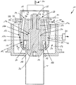
- the FIG. 1 shows a heating device 10, with which the edges of a filling opening of a single plastic tube body T of a tube by means of hot gas, such as hot air, can be heated.
- the heating device 10 has a housing 11, in which a lower insertion opening 12 is formed, the width of which is slightly larger than the diameter of the tube body T.
- a hot gas nozzle 13 is arranged, which has an inner first nozzle portion 13 a, which has a first hot gas duct 16 and in the interior of the tube body T introduced is, and has an outer second nozzle portion 13b, which has a second hot gas channel 19 and on the outside of the tube body T can be arranged.
- a vertical support rod 26 is mounted via a holder 25, at the lower end of a cone-shaped shielding member 14 is formed, which can dive into the interior of the tube body T and prevent the hot gas with a product located in the tube body T comes into contact.
- a first annular channel 17 is formed, which communicates at its upper end via a first connecting channel 16a with a feed channel 15 in connection, in which a hot gas is supplied, as indicated by the arrows H. is indicated.
- a hot-gas flow control device 30 is arranged, for example in the form of an adjustable throttle, with which the amount of hot gas supplied can be adjusted and changed.
- the first connection channel 16a and the first annular channel 17 are part of the first hot gas channel 16, which has at its lower end a substantially radially outwardly facing 1.
- hot gas outlet 18 which is between the top of the shielding element 14 and the lower edge of the first Cylinder wall 27 is formed.
- a first flow control device 23 is arranged, which is for example a continuously adjustable shut-off device 24 in the form of a slide or a throttle can act.
- a user can set which hot gas to flow through the 1st inner hot gas duct 16 or whether the first hot gas duct 16 is to be completely shut off.
- Downstream of the first flow control device 23 opens into the first connection channel 16a only schematically illustrated first cooling gas channel 32 in which a continuously adjustable shut-off device 33 is arranged, for example in the form of a slide or a throttle.
- a continuously adjustable shut-off device 33 By adjusting the shut-off device 33, a user can set whether and, if so, in what quantity the hot gas channel 16 in the first hot gas channel 16 is to be mixed with a cooler gas, for example ambient air, in order to adjust the temperature of the hot gas above the 1 Inner hot gas outlet 18 on the inside of the wall of the tube body T is applied to this.
- a first temperature sensor 34 is disposed above it, which is connected in an only schematically illustrated manner with an evaluation unit 35.
- the first temperature sensor 34 detects the temperature of the hot gas flowing in the first inner hot gas channel 16 and outputs a corresponding signal to the evaluation unit 35.
- the evaluation unit 35 can, depending on the measured values determined, the position of the hot gas flow control device 30 and / or the Adjust or change the flow control device 23 and / or the shut-off device 33 of the first cooling gas channel 32.
- a second annular channel 20 is formed, which communicates with the supply channel 15 via a second connecting channel 19a.
- the second connecting channel 19a and the second annular channel 20 are part of the outer second hot gas channel 19, which has at its lower end a second hot gas outlet 21, from which a radially inwardly directed hot gas flow emerges.
- the exiting hot gas flow may have a radial and / or tangential and / or axial, i. have directed downward in the interior of the tube body T component.
- the end of the inserted tube body T between the first hot gas outlet 18 and the second hot gas outlet 21 is arranged so that the emerging from the first hot gas outlet 18 hot gas to the inner wall of the tube body T and the emerging from the 2nd hot gas outlet 21 Hot gas on the outer wall of the tube body T occurs, wherein the first hot gas outlet 18 and the second hot gas outlet 21 are arranged offset in the longitudinal direction of the tube body T that the first hot gas outlet 18 by a small amount below the second hot gas outlet 21 is arranged.
- a second flow control device 29 is arranged, which may be, for example, a continuously adjustable shut-off device 36 in the form of a slide or a throttle.
- a user can set, which amount of hot gas through the second outer Hot gas duct 19 should flow or whether the second hot gas duct 19 should be completely shut off.
- Coolant gas channel 38 in which a continuously adjustable shut-off device 39 is arranged, for example in the form of a slide or a throttle.
- a continuously adjustable shut-off device 39 On the setting of the shut-off device 39, a user can set whether and, if so, in what quantity the hot outer gas flowing in the second outer hot gas 19 hot gas, a cooler gas, for example, ambient air, to be mixed, so as to adjust the temperature of the hot gas, over the 2nd Outer hot gas outlet 21 on the inside of the wall of the tube body T is applied to this.
- a cooler gas for example, ambient air
- a second temperature sensor 40 which is connected to the evaluation unit 35 in a schematically illustrated manner, is arranged in the second outer hot gas channel 19.
- the second temperature sensor 40 detects the temperature of the hot gas flowing in the second outer hot gas channel 19 and outputs a corresponding signal to the evaluation unit 35.
- the evaluation unit 35 can, depending on the measured values determined, the position of the hot gas flow control device 30 and / or the 2. Set or change the flow control device 29 and / or the shut-off device 39 of the second cooling gas channel 30.
- a likewise designed as an annular channel discharge channel 22 is arranged, through which the hot gas can be removed after acting on the wall of the tube body T, as indicated by the arrows A.
- this is first introduced with its upper open end from below through the insertion opening 12 of the housing 11 and disposed between the first hot gas outlet 18 and the second hot gas outlet 21, wherein the conical shielding element 14, which in the Tube body T dips, the orientation of the tube body T is used.
- the hot gas is applied through the first hot gas duct 16 and the first hot gas outlet 18 to the inside of the wall of the tube body T.
- the hot gas then flows between the wall of the tube body T and the first cylinder wall 27 upwards into a connecting channel 28, flows around the upper end of the tube body T and enters the discharge channel 22 and is discharged therefrom (arrows A).
- the hot gas enters at at least partially open shut-off device 36 in the 2nd hot gas channel 19 and exits at the second hot gas outlet 21 and acts on the outside of the wall of the tube body T and heats it.
- the hot gas passes directly into the discharge channel 22 and is discharged therefrom.
- the tube body T is then removed from the bottom of the heating device and closed in a conventional manner in a subsequent pressing station.
Landscapes
- Engineering & Computer Science (AREA)
- Mechanical Engineering (AREA)
- Physics & Mathematics (AREA)
- Thermal Sciences (AREA)
- Fluid Mechanics (AREA)
- Chemical & Material Sciences (AREA)
- Combustion & Propulsion (AREA)
- Oral & Maxillofacial Surgery (AREA)
- Health & Medical Sciences (AREA)
- Lining Or Joining Of Plastics Or The Like (AREA)
- Closing Of Containers (AREA)
- Package Closures (AREA)
- Furnace Details (AREA)
Claims (11)
- Dispositif de chauffage (10) pour chauffer les bords de l'orifice de remplissage d'un tube composé d'un corps de tube (T) individuel en forme de tube à l'aide de gaz chaud, avec une buse de gaz chaud (13) comportant une 1re section de buse (13a) pouvant être amenée dans un espace intérieur du corps de tube (T), possédant un 1er canal de gaz chaud (16) doté d'au moins une 1re sortie de gaz chaud (18) pouvant être disposée à l'intérieur de l'espace intérieur du corps de tube (T) et à l'aide de laquelle du gaz chaud peut être appliqué sur la paroi intérieure du corps de tube (T), la buse de gaz chaud (13) comportant une 2e section de buse (13b) possédant un 2e canal de gaz chaud (19) doté d'au moins une 2e sortie de gaz chaud (21) disposée sur le côté extérieur de la paroi du corps de tube (T) et à l'aide de laquelle du gaz chaud peut être appliqué sur la paroi extérieure du corps de tube (T) et un dispositif de commande de débit (23, 29) étant disposé dans le 1er canal de gaz chaud (16) et/ou dans le 2e canal de gaz chaud (19), caractérisé en ce qu'un capteur de température (34, 40) est disposé dans le 1er canal de gaz chaud (16) et/ou dans le 2e canal de gaz chaud (19) en vue de détecter la température du gaz circulant dans le canal de gaz chaud (16, 19), le capteur de température (34, 40) transmettant une valeur de température à un dispositif d'analyse (35) à l'aide duquel il est possible d'avoir une action sur les dispositifs de commande de débit (23, 29) en fonction des valeurs de température détectées.
- Dispositif de chauffage selon la revendication 1, caractérisé en ce que le dispositif de commande de débit (23, 29) comporte un dispositif d'arrêt (24, 36) réglable en continu.
- Dispositif de chauffage selon la revendication 1 ou 2, caractérisé en ce qu'un canal de gaz de refroidissement (32, 38) débouche dans le 1er canal de gaz chaud (16) et/ou dans le 2e canal de gaz chaud (19) en aval du dispositif de commande de débit (23, 29), un gaz plus froid pouvant être mélangé au gaz chaud circulant dans le canal de gaz chaud (16, 19) au travers dudit canal.
- Dispositif de chauffage selon la revendication 3, caractérisé en ce qu'un dispositif d'arrêt (33, 39) réglable est disposé dans le canal de gaz de refroidissement (32, 38).
- Dispositif de chauffage selon l'une quelconque des revendications 1 à 4, caractérisé en ce que le 1er canal de gaz chaud (16) et le 2e canal de gaz chaud (19) sont reliés à un canal d'alimentation (15) commun dans lequel le gaz chaud peut être amené.
- Dispositif de chauffage selon la revendication 5, caractérisé en ce qu'un dispositif de commande de débit de gaz chaud (30) est disposé dans le canal d'alimentation (15).
- Dispositif de chauffage selon l'une quelconque des revendications 1 à 6, caractérisé en ce que la 1re sortie de gaz chaud (18) est disposée de façon décalée par rapport à la 2e sortie de gaz chaud (21) dans la direction longitudinale du corps de tube (T).
- Dispositif de chauffage selon la revendication 7, caractérisé en ce que la 1re sortie de gaz chaud (18) est disposée en dessous de la 2e sortie de gaz chaud (21).
- Dispositif de chauffage selon l'une quelconque des revendications 1 à 8, caractérisé en ce que la 1re section de buse (13a) est disposée dans le plan radial à l'intérieur de la 2e section de buse (13b).
- Dispositif de chauffage selon l'une quelconque des revendications 1 à 9, caractérisé en ce que le gaz chaud sortant de la 1re sortie de gaz chaud (18) et le gaz chaud sortant de la 2e sortie de gaz chaud (21) peuvent être évacués à l'aide d'un canal d'évacuation (22) commun.
- Dispositif de chauffage selon la revendication 10, caractérisé en ce que le canal d'évacuation (22) entoure au moins en partie la buse de gaz chaud (13).
Applications Claiming Priority (2)
| Application Number | Priority Date | Filing Date | Title |
|---|---|---|---|
| DE102013014484.1A DE102013014484A1 (de) | 2013-09-02 | 2013-09-02 | Erwärmvorrichtung zum Erwärmen der Ränder der Einfüllöffnung einer Tube |
| PCT/EP2014/002325 WO2015028144A1 (fr) | 2013-09-02 | 2014-08-26 | Dispositif de chauffage des bords de l'orifice de remplissage d'un tube |
Publications (2)
| Publication Number | Publication Date |
|---|---|
| EP3041663A1 EP3041663A1 (fr) | 2016-07-13 |
| EP3041663B1 true EP3041663B1 (fr) | 2018-12-26 |
Family
ID=51541045
Family Applications (1)
| Application Number | Title | Priority Date | Filing Date |
|---|---|---|---|
| EP14766106.0A Not-in-force EP3041663B1 (fr) | 2013-09-02 | 2014-08-26 | Dispositif de chauffage des bords de l'orifice de remplissage d'un tube |
Country Status (5)
| Country | Link |
|---|---|
| US (1) | US20160200010A1 (fr) |
| EP (1) | EP3041663B1 (fr) |
| DE (1) | DE102013014484A1 (fr) |
| MX (1) | MX2016002712A (fr) |
| WO (1) | WO2015028144A1 (fr) |
Families Citing this family (2)
| Publication number | Priority date | Publication date | Assignee | Title |
|---|---|---|---|---|
| CN115816808A (zh) * | 2022-07-07 | 2023-03-21 | 四川金石东方新材料科技有限公司 | 增强复合管的封口方法和封口设备 |
| CN115891127A (zh) * | 2022-11-29 | 2023-04-04 | 华创天元实业发展有限责任公司 | 一种大口径多重缠绕钢塑复合管封口用端盘加热装置 |
Family Cites Families (12)
| Publication number | Priority date | Publication date | Assignee | Title |
|---|---|---|---|---|
| CH370232A (de) * | 1958-07-04 | 1963-06-30 | Agfa Ag | Verfahren und Gerät zum Verschliessen eines Behälters aus Kunststoff |
| US3823306A (en) * | 1973-01-30 | 1974-07-09 | R Davis | Hot air sealing apparatus |
| US3825408A (en) * | 1973-09-07 | 1974-07-23 | Phillips Petroleum Co | Hot air heater for carton sealing machine |
| US4262708A (en) * | 1979-09-14 | 1981-04-21 | Reynolds Metals Company | Method and apparatus for treating flexible containers |
| FI811410L (fi) * | 1981-05-07 | 1982-11-08 | Asko Upo Oy | Foerfarande foer uppvaermning av aendan i ett plastroer och cirkulationsluftugn foer utfoerande av foerfarandet. ec;g;820614:17;l |
| SE8300277L (sv) * | 1983-01-20 | 1984-07-21 | Norden Packaging Mach | Forseglingsanordning |
| DE3744402A1 (de) | 1987-12-29 | 1989-07-13 | Iwk Verpackungstechnik Gmbh | Verfahren und vorrichtung zum zentrieren von tuben |
| US4933041A (en) * | 1988-03-10 | 1990-06-12 | R. A. Jones & Co. Inc. | Method and apparatus for sealing plastic tubes |
| SE9102511D0 (sv) * | 1991-09-03 | 1991-09-03 | Norden Pac Dev Ab | Method and apparatus for manufacturing a containerfilled with a product |
| SE523289C2 (sv) * | 2001-12-11 | 2004-04-06 | Norden Pac Dev Ab | Tubfyllningsmaskin och förfaranden i en sådan |
| JP3638567B2 (ja) * | 2002-04-30 | 2005-04-13 | ワイエル工業株式会社 | 樹脂性チューブのシール部加熱装置 |
| SE532090C2 (sv) * | 2008-02-22 | 2009-10-20 | Norden Machinery Ab | Hetgasmunstycke anpassat för att värma en dubbeltub,tubfyllningsmaskin innefattande ett hetgasmunstycke samt en metod för att försluta en dubbeltub |
-
2013
- 2013-09-02 DE DE102013014484.1A patent/DE102013014484A1/de not_active Withdrawn
-
2014
- 2014-08-26 MX MX2016002712A patent/MX2016002712A/es unknown
- 2014-08-26 EP EP14766106.0A patent/EP3041663B1/fr not_active Not-in-force
- 2014-08-26 US US14/912,690 patent/US20160200010A1/en not_active Abandoned
- 2014-08-26 WO PCT/EP2014/002325 patent/WO2015028144A1/fr not_active Ceased
Non-Patent Citations (1)
| Title |
|---|
| None * |
Also Published As
| Publication number | Publication date |
|---|---|
| DE102013014484A1 (de) | 2015-03-05 |
| MX2016002712A (es) | 2016-06-08 |
| WO2015028144A1 (fr) | 2015-03-05 |
| EP3041663A1 (fr) | 2016-07-13 |
| US20160200010A1 (en) | 2016-07-14 |
Similar Documents
| Publication | Publication Date | Title |
|---|---|---|
| DE10038158B4 (de) | Verfahren und Vorrichtung zum Verbinden von Gegenständen mittels plastisch verformbarer Verbindungskörper | |
| EP2958723B1 (fr) | Granulateur à cylindres broyeurs et son utilisation | |
| DE102009040802A1 (de) | Verfahren und Vorrichtung zum Aufbringen einer Dichtungsmasse auf eine Fläche | |
| EP2404735B1 (fr) | Procédé et dispositif pour la conduite d'une ligne d'extrusion de tuyaux | |
| EP3041663B1 (fr) | Dispositif de chauffage des bords de l'orifice de remplissage d'un tube | |
| DE60211218T2 (de) | Schlauchfüllmaschine und verfahren zum verschliessen der schlauchenden in solch einer maschine | |
| DE102014212931B4 (de) | Harzabgabemechanismus | |
| EP2155467B1 (fr) | Appareil de production de tubes ronds ou ovales en matière plastique | |
| DE60122004T2 (de) | Verfahren und vorrichtung zur herstellung eines polymeren behältersystems für druckbeaufschlagte fluide | |
| WO2019091768A1 (fr) | Poste de formage et de remplissage d'une installation destinée à produire des récipients remplis à partir de préformes grâce à un produit de remplissage introduit sous pression dans la préforme | |
| EP1880823A1 (fr) | Dispositif de fabrication de préformes de type tuyaux | |
| EP3562540B1 (fr) | Procédé et dispositif pour emmancher un flexible sur une tétine d'étanchéité de forme stable | |
| EP2666611B1 (fr) | Procédé et dispositif destinés à tempérer une masse en matière plastique | |
| DE102009049275A1 (de) | Verfahren und Vorrichtung zum Trocknen von Kunststoffgranulaten | |
| DE102009019192A1 (de) | Kurzraupenpistole | |
| DE102005060979A1 (de) | Verfahren und Vorrichtung zum Herstellen von Blasfolien aus thermoplastischen Kunststoffen | |
| EP2958730B1 (fr) | Dispositif de fabrication de tuyaux en matière plastique | |
| EP3452264A1 (fr) | Poste de formage et de remplissage d'une installation destinée à produire des récipients remplis, à partir de préformes, par un produit de remplissage introduit sous pression dans la préforme | |
| EP4522360B1 (fr) | Dispositif de coulée et procédé de préchauffage d'un dispositif de transport de fusion d'un dispositif de coulée | |
| DE3714593C2 (fr) | ||
| DE102010023302B4 (de) | Wendelverteiler, Blaskopf, Blasfolienanlage, Verfahren zum Herstellen einer Blasfolie | |
| EP1245366B1 (fr) | Mécanisme de blocage pour le contrôle du flux d'un milieu coulant | |
| EP2401134B1 (fr) | Extrudeuse-soudeuse manuelle comprenant une semelle de soudage monobloc en plastique | |
| DE10205210B4 (de) | Vorrichtung zur Herstellung von Kunststoffrohren | |
| DE102009026562B4 (de) | Extrusionskopf |
Legal Events
| Date | Code | Title | Description |
|---|---|---|---|
| PUAI | Public reference made under article 153(3) epc to a published international application that has entered the european phase |
Free format text: ORIGINAL CODE: 0009012 |
|
| 17P | Request for examination filed |
Effective date: 20160129 |
|
| AK | Designated contracting states |
Kind code of ref document: A1 Designated state(s): AL AT BE BG CH CY CZ DE DK EE ES FI FR GB GR HR HU IE IS IT LI LT LU LV MC MK MT NL NO PL PT RO RS SE SI SK SM TR |
|
| AX | Request for extension of the european patent |
Extension state: BA ME |
|
| DAX | Request for extension of the european patent (deleted) | ||
| GRAP | Despatch of communication of intention to grant a patent |
Free format text: ORIGINAL CODE: EPIDOSNIGR1 |
|
| STAA | Information on the status of an ep patent application or granted ep patent |
Free format text: STATUS: GRANT OF PATENT IS INTENDED |
|
| INTG | Intention to grant announced |
Effective date: 20180927 |
|
| GRAS | Grant fee paid |
Free format text: ORIGINAL CODE: EPIDOSNIGR3 |
|
| GRAA | (expected) grant |
Free format text: ORIGINAL CODE: 0009210 |
|
| STAA | Information on the status of an ep patent application or granted ep patent |
Free format text: STATUS: THE PATENT HAS BEEN GRANTED |
|
| AK | Designated contracting states |
Kind code of ref document: B1 Designated state(s): AL AT BE BG CH CY CZ DE DK EE ES FI FR GB GR HR HU IE IS IT LI LT LU LV MC MK MT NL NO PL PT RO RS SE SI SK SM TR |
|
| REG | Reference to a national code |
Ref country code: GB Ref legal event code: FG4D Free format text: NOT ENGLISH |
|
| REG | Reference to a national code |
Ref country code: CH Ref legal event code: EP |
|
| REG | Reference to a national code |
Ref country code: DE Ref legal event code: R096 Ref document number: 502014010483 Country of ref document: DE |
|
| REG | Reference to a national code |
Ref country code: AT Ref legal event code: REF Ref document number: 1080803 Country of ref document: AT Kind code of ref document: T Effective date: 20190115 |
|
| REG | Reference to a national code |
Ref country code: IE Ref legal event code: FG4D Free format text: LANGUAGE OF EP DOCUMENT: GERMAN |
|
| REG | Reference to a national code |
Ref country code: SE Ref legal event code: TRGR |
|
| PG25 | Lapsed in a contracting state [announced via postgrant information from national office to epo] |
Ref country code: BG Free format text: LAPSE BECAUSE OF FAILURE TO SUBMIT A TRANSLATION OF THE DESCRIPTION OR TO PAY THE FEE WITHIN THE PRESCRIBED TIME-LIMIT Effective date: 20190326 Ref country code: LT Free format text: LAPSE BECAUSE OF FAILURE TO SUBMIT A TRANSLATION OF THE DESCRIPTION OR TO PAY THE FEE WITHIN THE PRESCRIBED TIME-LIMIT Effective date: 20181226 Ref country code: NO Free format text: LAPSE BECAUSE OF FAILURE TO SUBMIT A TRANSLATION OF THE DESCRIPTION OR TO PAY THE FEE WITHIN THE PRESCRIBED TIME-LIMIT Effective date: 20190326 Ref country code: HR Free format text: LAPSE BECAUSE OF FAILURE TO SUBMIT A TRANSLATION OF THE DESCRIPTION OR TO PAY THE FEE WITHIN THE PRESCRIBED TIME-LIMIT Effective date: 20181226 Ref country code: LV Free format text: LAPSE BECAUSE OF FAILURE TO SUBMIT A TRANSLATION OF THE DESCRIPTION OR TO PAY THE FEE WITHIN THE PRESCRIBED TIME-LIMIT Effective date: 20181226 Ref country code: FI Free format text: LAPSE BECAUSE OF FAILURE TO SUBMIT A TRANSLATION OF THE DESCRIPTION OR TO PAY THE FEE WITHIN THE PRESCRIBED TIME-LIMIT Effective date: 20181226 |
|
| REG | Reference to a national code |
Ref country code: NL Ref legal event code: MP Effective date: 20181226 |
|
| REG | Reference to a national code |
Ref country code: LT Ref legal event code: MG4D |
|
| PG25 | Lapsed in a contracting state [announced via postgrant information from national office to epo] |
Ref country code: AL Free format text: LAPSE BECAUSE OF FAILURE TO SUBMIT A TRANSLATION OF THE DESCRIPTION OR TO PAY THE FEE WITHIN THE PRESCRIBED TIME-LIMIT Effective date: 20181226 Ref country code: RS Free format text: LAPSE BECAUSE OF FAILURE TO SUBMIT A TRANSLATION OF THE DESCRIPTION OR TO PAY THE FEE WITHIN THE PRESCRIBED TIME-LIMIT Effective date: 20181226 Ref country code: GR Free format text: LAPSE BECAUSE OF FAILURE TO SUBMIT A TRANSLATION OF THE DESCRIPTION OR TO PAY THE FEE WITHIN THE PRESCRIBED TIME-LIMIT Effective date: 20190327 |
|
| PG25 | Lapsed in a contracting state [announced via postgrant information from national office to epo] |
Ref country code: NL Free format text: LAPSE BECAUSE OF FAILURE TO SUBMIT A TRANSLATION OF THE DESCRIPTION OR TO PAY THE FEE WITHIN THE PRESCRIBED TIME-LIMIT Effective date: 20181226 |
|
| PG25 | Lapsed in a contracting state [announced via postgrant information from national office to epo] |
Ref country code: PT Free format text: LAPSE BECAUSE OF FAILURE TO SUBMIT A TRANSLATION OF THE DESCRIPTION OR TO PAY THE FEE WITHIN THE PRESCRIBED TIME-LIMIT Effective date: 20190426 Ref country code: PL Free format text: LAPSE BECAUSE OF FAILURE TO SUBMIT A TRANSLATION OF THE DESCRIPTION OR TO PAY THE FEE WITHIN THE PRESCRIBED TIME-LIMIT Effective date: 20181226 Ref country code: CZ Free format text: LAPSE BECAUSE OF FAILURE TO SUBMIT A TRANSLATION OF THE DESCRIPTION OR TO PAY THE FEE WITHIN THE PRESCRIBED TIME-LIMIT Effective date: 20181226 Ref country code: ES Free format text: LAPSE BECAUSE OF FAILURE TO SUBMIT A TRANSLATION OF THE DESCRIPTION OR TO PAY THE FEE WITHIN THE PRESCRIBED TIME-LIMIT Effective date: 20181226 |
|
| PG25 | Lapsed in a contracting state [announced via postgrant information from national office to epo] |
Ref country code: SM Free format text: LAPSE BECAUSE OF FAILURE TO SUBMIT A TRANSLATION OF THE DESCRIPTION OR TO PAY THE FEE WITHIN THE PRESCRIBED TIME-LIMIT Effective date: 20181226 Ref country code: EE Free format text: LAPSE BECAUSE OF FAILURE TO SUBMIT A TRANSLATION OF THE DESCRIPTION OR TO PAY THE FEE WITHIN THE PRESCRIBED TIME-LIMIT Effective date: 20181226 Ref country code: IS Free format text: LAPSE BECAUSE OF FAILURE TO SUBMIT A TRANSLATION OF THE DESCRIPTION OR TO PAY THE FEE WITHIN THE PRESCRIBED TIME-LIMIT Effective date: 20190426 Ref country code: SK Free format text: LAPSE BECAUSE OF FAILURE TO SUBMIT A TRANSLATION OF THE DESCRIPTION OR TO PAY THE FEE WITHIN THE PRESCRIBED TIME-LIMIT Effective date: 20181226 Ref country code: RO Free format text: LAPSE BECAUSE OF FAILURE TO SUBMIT A TRANSLATION OF THE DESCRIPTION OR TO PAY THE FEE WITHIN THE PRESCRIBED TIME-LIMIT Effective date: 20181226 |
|
| REG | Reference to a national code |
Ref country code: DE Ref legal event code: R097 Ref document number: 502014010483 Country of ref document: DE |
|
| PG25 | Lapsed in a contracting state [announced via postgrant information from national office to epo] |
Ref country code: DK Free format text: LAPSE BECAUSE OF FAILURE TO SUBMIT A TRANSLATION OF THE DESCRIPTION OR TO PAY THE FEE WITHIN THE PRESCRIBED TIME-LIMIT Effective date: 20181226 |
|
| PLBE | No opposition filed within time limit |
Free format text: ORIGINAL CODE: 0009261 |
|
| STAA | Information on the status of an ep patent application or granted ep patent |
Free format text: STATUS: NO OPPOSITION FILED WITHIN TIME LIMIT |
|
| 26N | No opposition filed |
Effective date: 20190927 |
|
| PG25 | Lapsed in a contracting state [announced via postgrant information from national office to epo] |
Ref country code: SI Free format text: LAPSE BECAUSE OF FAILURE TO SUBMIT A TRANSLATION OF THE DESCRIPTION OR TO PAY THE FEE WITHIN THE PRESCRIBED TIME-LIMIT Effective date: 20181226 |
|
| PG25 | Lapsed in a contracting state [announced via postgrant information from national office to epo] |
Ref country code: TR Free format text: LAPSE BECAUSE OF FAILURE TO SUBMIT A TRANSLATION OF THE DESCRIPTION OR TO PAY THE FEE WITHIN THE PRESCRIBED TIME-LIMIT Effective date: 20181226 |
|
| PG25 | Lapsed in a contracting state [announced via postgrant information from national office to epo] |
Ref country code: CH Free format text: LAPSE BECAUSE OF NON-PAYMENT OF DUE FEES Effective date: 20190831 Ref country code: LU Free format text: LAPSE BECAUSE OF NON-PAYMENT OF DUE FEES Effective date: 20190826 Ref country code: LI Free format text: LAPSE BECAUSE OF NON-PAYMENT OF DUE FEES Effective date: 20190831 Ref country code: MC Free format text: LAPSE BECAUSE OF FAILURE TO SUBMIT A TRANSLATION OF THE DESCRIPTION OR TO PAY THE FEE WITHIN THE PRESCRIBED TIME-LIMIT Effective date: 20181226 |
|
| REG | Reference to a national code |
Ref country code: BE Ref legal event code: MM Effective date: 20190831 |
|
| PG25 | Lapsed in a contracting state [announced via postgrant information from national office to epo] |
Ref country code: BE Free format text: LAPSE BECAUSE OF NON-PAYMENT OF DUE FEES Effective date: 20190831 |
|
| REG | Reference to a national code |
Ref country code: AT Ref legal event code: MM01 Ref document number: 1080803 Country of ref document: AT Kind code of ref document: T Effective date: 20190826 |
|
| PGFP | Annual fee paid to national office [announced via postgrant information from national office to epo] |
Ref country code: DE Payment date: 20200821 Year of fee payment: 7 Ref country code: FR Payment date: 20200819 Year of fee payment: 7 Ref country code: IE Payment date: 20200818 Year of fee payment: 7 Ref country code: GB Payment date: 20200824 Year of fee payment: 7 |
|
| PG25 | Lapsed in a contracting state [announced via postgrant information from national office to epo] |
Ref country code: AT Free format text: LAPSE BECAUSE OF NON-PAYMENT OF DUE FEES Effective date: 20190826 |
|
| PGFP | Annual fee paid to national office [announced via postgrant information from national office to epo] |
Ref country code: SE Payment date: 20200824 Year of fee payment: 7 Ref country code: IT Payment date: 20200831 Year of fee payment: 7 |
|
| PG25 | Lapsed in a contracting state [announced via postgrant information from national office to epo] |
Ref country code: CY Free format text: LAPSE BECAUSE OF FAILURE TO SUBMIT A TRANSLATION OF THE DESCRIPTION OR TO PAY THE FEE WITHIN THE PRESCRIBED TIME-LIMIT Effective date: 20181226 |
|
| PG25 | Lapsed in a contracting state [announced via postgrant information from national office to epo] |
Ref country code: HU Free format text: LAPSE BECAUSE OF FAILURE TO SUBMIT A TRANSLATION OF THE DESCRIPTION OR TO PAY THE FEE WITHIN THE PRESCRIBED TIME-LIMIT; INVALID AB INITIO Effective date: 20140826 Ref country code: MT Free format text: LAPSE BECAUSE OF FAILURE TO SUBMIT A TRANSLATION OF THE DESCRIPTION OR TO PAY THE FEE WITHIN THE PRESCRIBED TIME-LIMIT Effective date: 20181226 |
|
| REG | Reference to a national code |
Ref country code: DE Ref legal event code: R119 Ref document number: 502014010483 Country of ref document: DE |
|
| REG | Reference to a national code |
Ref country code: SE Ref legal event code: EUG |
|
| GBPC | Gb: european patent ceased through non-payment of renewal fee |
Effective date: 20210826 |
|
| PG25 | Lapsed in a contracting state [announced via postgrant information from national office to epo] |
Ref country code: SE Free format text: LAPSE BECAUSE OF NON-PAYMENT OF DUE FEES Effective date: 20210827 |
|
| PG25 | Lapsed in a contracting state [announced via postgrant information from national office to epo] |
Ref country code: MK Free format text: LAPSE BECAUSE OF FAILURE TO SUBMIT A TRANSLATION OF THE DESCRIPTION OR TO PAY THE FEE WITHIN THE PRESCRIBED TIME-LIMIT Effective date: 20181226 |
|
| PG25 | Lapsed in a contracting state [announced via postgrant information from national office to epo] |
Ref country code: IT Free format text: LAPSE BECAUSE OF NON-PAYMENT OF DUE FEES Effective date: 20210826 Ref country code: IE Free format text: LAPSE BECAUSE OF NON-PAYMENT OF DUE FEES Effective date: 20210826 Ref country code: GB Free format text: LAPSE BECAUSE OF NON-PAYMENT OF DUE FEES Effective date: 20210826 Ref country code: FR Free format text: LAPSE BECAUSE OF NON-PAYMENT OF DUE FEES Effective date: 20210831 Ref country code: DE Free format text: LAPSE BECAUSE OF NON-PAYMENT OF DUE FEES Effective date: 20220301 |