EP3041177B1 - Data transmission method and apparatus - Google Patents
Data transmission method and apparatus Download PDFInfo
- Publication number
- EP3041177B1 EP3041177B1 EP13893212.4A EP13893212A EP3041177B1 EP 3041177 B1 EP3041177 B1 EP 3041177B1 EP 13893212 A EP13893212 A EP 13893212A EP 3041177 B1 EP3041177 B1 EP 3041177B1
- Authority
- EP
- European Patent Office
- Prior art keywords
- target
- layer data
- mac layer
- data group
- physical
- Prior art date
- Legal status (The legal status is an assumption and is not a legal conclusion. Google has not performed a legal analysis and makes no representation as to the accuracy of the status listed.)
- Active
Links
- 238000000034 method Methods 0.000 title claims description 111
- 230000005540 biological transmission Effects 0.000 title claims description 109
- 238000012545 processing Methods 0.000 claims description 165
- 238000013507 mapping Methods 0.000 claims description 29
- 238000006243 chemical reaction Methods 0.000 claims description 26
- 230000001419 dependent effect Effects 0.000 claims description 15
- 238000010586 diagram Methods 0.000 description 19
- 101150102703 BIP3 gene Proteins 0.000 description 13
- 239000003550 marker Substances 0.000 description 13
- 238000004891 communication Methods 0.000 description 12
- 230000006870 function Effects 0.000 description 11
- 230000003287 optical effect Effects 0.000 description 5
- 238000012937 correction Methods 0.000 description 3
- 230000008878 coupling Effects 0.000 description 3
- 238000010168 coupling process Methods 0.000 description 3
- 238000005859 coupling reaction Methods 0.000 description 3
- 230000006835 compression Effects 0.000 description 2
- 238000007906 compression Methods 0.000 description 2
- 238000003780 insertion Methods 0.000 description 2
- 230000037431 insertion Effects 0.000 description 2
- 230000000737 periodic effect Effects 0.000 description 2
- 230000001360 synchronised effect Effects 0.000 description 2
- 108700026140 MAC combination Proteins 0.000 description 1
- 238000013461 design Methods 0.000 description 1
- 238000011161 development Methods 0.000 description 1
- 238000005516 engineering process Methods 0.000 description 1
- 238000012423 maintenance Methods 0.000 description 1
- 238000010295 mobile communication Methods 0.000 description 1
- 239000013307 optical fiber Substances 0.000 description 1
- 238000012546 transfer Methods 0.000 description 1
Images


Classifications
-
- H—ELECTRICITY
- H04—ELECTRIC COMMUNICATION TECHNIQUE
- H04L—TRANSMISSION OF DIGITAL INFORMATION, e.g. TELEGRAPHIC COMMUNICATION
- H04L12/00—Data switching networks
- H04L12/66—Arrangements for connecting between networks having differing types of switching systems, e.g. gateways
-
- H—ELECTRICITY
- H04—ELECTRIC COMMUNICATION TECHNIQUE
- H04L—TRANSMISSION OF DIGITAL INFORMATION, e.g. TELEGRAPHIC COMMUNICATION
- H04L12/00—Data switching networks
- H04L12/28—Data switching networks characterised by path configuration, e.g. LAN [Local Area Networks] or WAN [Wide Area Networks]
- H04L12/46—Interconnection of networks
- H04L12/4604—LAN interconnection over a backbone network, e.g. Internet, Frame Relay
- H04L12/462—LAN interconnection over a bridge based backbone
-
- H—ELECTRICITY
- H04—ELECTRIC COMMUNICATION TECHNIQUE
- H04L—TRANSMISSION OF DIGITAL INFORMATION, e.g. TELEGRAPHIC COMMUNICATION
- H04L41/00—Arrangements for maintenance, administration or management of data switching networks, e.g. of packet switching networks
- H04L41/02—Standardisation; Integration
- H04L41/0226—Mapping or translating multiple network management protocols
-
- H—ELECTRICITY
- H04—ELECTRIC COMMUNICATION TECHNIQUE
- H04L—TRANSMISSION OF DIGITAL INFORMATION, e.g. TELEGRAPHIC COMMUNICATION
- H04L47/00—Traffic control in data switching networks
- H04L47/10—Flow control; Congestion control
- H04L47/41—Flow control; Congestion control by acting on aggregated flows or links
-
- H—ELECTRICITY
- H04—ELECTRIC COMMUNICATION TECHNIQUE
- H04L—TRANSMISSION OF DIGITAL INFORMATION, e.g. TELEGRAPHIC COMMUNICATION
- H04L69/00—Network arrangements, protocols or services independent of the application payload and not provided for in the other groups of this subclass
- H04L69/30—Definitions, standards or architectural aspects of layered protocol stacks
- H04L69/32—Architecture of open systems interconnection [OSI] 7-layer type protocol stacks, e.g. the interfaces between the data link level and the physical level
- H04L69/322—Intralayer communication protocols among peer entities or protocol data unit [PDU] definitions
- H04L69/324—Intralayer communication protocols among peer entities or protocol data unit [PDU] definitions in the data link layer [OSI layer 2], e.g. HDLC
-
- H—ELECTRICITY
- H04—ELECTRIC COMMUNICATION TECHNIQUE
- H04L—TRANSMISSION OF DIGITAL INFORMATION, e.g. TELEGRAPHIC COMMUNICATION
- H04L1/00—Arrangements for detecting or preventing errors in the information received
- H04L2001/0092—Error control systems characterised by the topology of the transmission link
- H04L2001/0093—Point-to-multipoint
-
- Y—GENERAL TAGGING OF NEW TECHNOLOGICAL DEVELOPMENTS; GENERAL TAGGING OF CROSS-SECTIONAL TECHNOLOGIES SPANNING OVER SEVERAL SECTIONS OF THE IPC; TECHNICAL SUBJECTS COVERED BY FORMER USPC CROSS-REFERENCE ART COLLECTIONS [XRACs] AND DIGESTS
- Y02—TECHNOLOGIES OR APPLICATIONS FOR MITIGATION OR ADAPTATION AGAINST CLIMATE CHANGE
- Y02D—CLIMATE CHANGE MITIGATION TECHNOLOGIES IN INFORMATION AND COMMUNICATION TECHNOLOGIES [ICT], I.E. INFORMATION AND COMMUNICATION TECHNOLOGIES AIMING AT THE REDUCTION OF THEIR OWN ENERGY USE
- Y02D30/00—Reducing energy consumption in communication networks
- Y02D30/50—Reducing energy consumption in communication networks in wire-line communication networks, e.g. low power modes or reduced link rate
Definitions
- the present invention relates to the communications field, and in particular to a data transmission method and apparatus.
- Ethernet transfer rate has increased from 10 M(Megabit), 100 M, 1 G(Gigabit), 10 G to the current 40 G and 100 G.
- 40 G Ethernet and 100 G Ethernet have been widely applied. Therefore, a situation occurs in which a plurality of rates coexist. Ethernet interfaces of a plurality of rate levels cannot be interconnected. For example, in the prior art, 10 G, 40 G and 100 G Ethernet interfaces cannot be interconnected and a higher rate is not backward compatible. There are many types of device boards and a large number of spare parts and different boards need to be designed for different rates, thereby causing high maintenance costs.
- US 6,094,439 discloses a Gigabit network having a media access controller outputting packet data at Gigabit rates uses multiple 100MB/s physical layer links coupled to a physical interface having a data router to enable implementation of a Gigabit network using low cost data links.
- a multi-Media Independent Interface may output separate packet data on separate physical layer links to increase the effective data transmission rate, may output the same packet data on multiple transmission paths to improve quality of service, or any combination thereof.
- WO 98/45991 discloses a 200 Mbps PHY/MAC combination for providing full duplex operation at 400 Mbps.
- the PHY/MAC uses all 4 pairs of wire to create a signal channel.
- the PHY/MAC comprises a T2 physical layer device, a media access control entity, a medium independent interface, and a switch.
- the medium independent interface includes means for providing eight bit wide transmit data paths that are clocked at 25 MHz, thereby each providing a 200 Mbps data path between the medium access control layer and the physical layer device.
- US 2004/0156330 A1 discloses that at least two common logical channels of the same type are multiplexed to the same transport channel in a mobile communication system.
- a Common Logical channel Identifier (CLI) is defined and inserted into a MAC PDU header so that the different logical channels can be identified.
- CLI Common Logical channel Identifier
- Embodiments of the present invention provide a data transmission method, which can meet a requirement for an Ethernet network with diversified rate levels.
- a data transmission method includes: performing, at a physical layer by a transmit end device, grouping processing on at least one piece of media access control (MAC) layer data that comes from a MAC layer, to determine at least one MAC layer data group; allocating, according to target bandwidth required by a target MAC layer data group and preset reference bandwidth of a logical channel, at least one target logical channel from N logical channels to the target MAC layer data group, so that the at least one target logical channel corresponds to only the target MAC layer data group, wherein a logical channel is multiplexed to one physical channel; performing encoding processing on the target MAC layer data group according to the at least one target logical channel to generate target physical layer data, where the at least one target logical channel corresponds to only the target physical layer data; and sending the target physical layer data and first indication information to a target receive end device of at least one receive end device, where the first indication information is used to indicate a mapping relationship between the target MAC layer data
- MAC media access control
- the sending the target physical layer data to a target receive end device of at least one receive end device includes: determining a target logical port from at least one logical port, where one logical port corresponds to at least one physical channel; and sending the target physical layer data to the target receive end device through the at least one physical channel corresponding to the target logical port.
- the allocating, at the RS or PCS of the transmit device, according to target bandwidth required by a target MAC layer data group and preset reference bandwidth of a logical channel, at least one target logical channel to the target MAC layer data group includes: determining, at the RS of the transmit device, the at least one target logical channel according to the target bandwidth and the reference bandwidth, and sending second indication information to the PCS of the transmit device, where the second indication information is used to indicate the at least one target logical channel; and the performing, at the PCS of the transmit device, encoding processing on the target MAC layer data group according to the at least one target logical channel includes: determining, at the PCS of the transmit device, the at least one target logical channel according to the second indication information, and performing encoding processing on the target MAC layer data group according to the at least one target logical channel.
- the physical layer includes the RS, a media independent interface, and the PCS, where the media independent interface is arranged between the RS and the PCS and used for data transmission between the RS and the PCS by using N timeslots, where one timeslot is used to transmit data in one logical channel;
- the allocating, at the RS or PCS of the transmit device, according to target bandwidth required by a target MAC layer data group and preset reference bandwidth of a logical channel, at least one target logical channel to the target MAC layer data group includes: determining, at the RS of the transmit device, according to the target bandwidth and the reference bandwidth, the number of target logical channels and the number of target timeslots that are on the media independent interface and used to transmit the target MAC layer data group; sending, on the media independent interface, the target MAC layer data group to the PCS by using the target timeslots; and allocating, at the PCS,
- a data transmission method includes: receiving, at a physical medium dependent sublayer, PMD, of a receive end device, target physical layer data and first indication information that are sent by a target transmit end device of at least one transmit end device; determining, at a physical coding sublayer, PCS, of the receive end device, from N logical channels according to the first indication information, at least one target logical channel that corresponds to only a target MAC layer data group, where the first indication information specifies a mapping relationship between the target MAC layer data group and the at least one target logical channel, wherein one physical channel is demultiplexed into multiple logical channels; and performing , at the PCS of the receive end device, decoding processing on the target physical layer data according to the at least one target logical channel to acquire the target MAC layer data group.
- PMD physical medium dependent sublayer
- PCS physical coding sublayer
- a physical layer includes a reconciliation sublayer, RS, and the PCS; the performing, at the PCS of the receive end device, decoding processing on the target physical layer data according to the at least one target logical channel to acquire the target MAC layer data group includes: sending, at the PCS of the receive end device, the target MAC layer data group to the RS of the receive end device, according to the at least one target logical channel, so that conversion between the physical layer and a MAC layer is performed on the target MAC layer data group at the RS and data obtained after the conversion is sent to the MAC layer.
- the physical layer further includes a media independent interface, where the media independent interface is arranged between the RS and the PCS and used for data transmission between the RS and the PCS by using N timeslots, where one timeslot is used to transmit data in one logical channel; and the sending, at the PCS, the target MAC layer data group to the RS according to the at least one target logical channel includes: determining, at the PCS according to the at least one target logical channel, a target timeslot that is on the media independent interface and used to transmit the target MAC layer data group; and sending, on the media independent interface, the target MAC layer data group to the RS by using the target timeslot, so that the target MAC layer data group is determined at the RS according to the target timeslot.
- the performing, at the PCS of the receive end device, decoding processing on the target physical layer data according to the at least one target logical channel to acquire the target MAC layer data group is specifically: taking the at least one target logical channel corresponding to the target physical layer data as one group, and performing decoding processing on the target physical layer data by taking a group as a unit, to generate the target MAC layer data group.
- a data transmission apparatus includes: a data group determining unit, configured to perform, at a reconciliation sublayer, RS, or a layer above a physical layer, grouping processing on at least one piece of MAC layer data that comes from a MAC layer, to determine at least one MAC layer data group; a logical channel determining unit, configured to allocate, at the RS or a physical coding sublayer, PCS, according to target bandwidth required by a target MAC layer data group of the at least one MAC layer data group determined by the data group determining unit and preset reference bandwidth of a logical channel, at least one target logical channel from N logical channels to the target MAC layer data group, so that the at least one target logical channel corresponds to only the target MAC layer data group, wherein multiple logical channels are multiplexed to one physical channel; an encoding processing unit, configured to perform, at the PCS, encoding processing on the target MAC layer data group according to the at least one target logical channel
- the sending unit is specifically configured to determine a target logical port from at least one logical port, where one logical port comprises the one or more physical channels; and send the target physical layer data to the target receive end device through the target logical port.
- a physical layer includes the RS, a media independent interface, and the PCS, where the media independent interface is arranged between the RS and the PCS and used for data transmission between the RS and the PCS by using N timeslots, where one timeslot is used to transmit data in one logical channel;
- the logical channel determining unit is specifically configured to determine, at the RS according to the target bandwidth and the reference bandwidth, the number of target logical channels and the number of target timeslots that are on the media independent interface and used to transmit the target MAC layer data group; send, on the media independent interface, the target MAC layer data group to the PCS by using the target timeslots; and allocate, at the PCS, the at least one logical channel to the target MAC layer data group as the target logical channel according to the number of the target timeslots.
- a data transmission apparatus includes: a receiving unit, configured to acquire, at a physical medium dependent sublayer, PMD, target physical layer data and first indication information that are sent by a target transmit end device of at least one transmit end device; a logical channel determining unit, configured to determine, at a physical coding sublayer, PCS, from N logical channels according to the first indication information acquired by the receiving unit, at least one target logical channel that corresponds to only a target media access control, MAC, layer data group, wherein the first indication information specifies a mapping relationship between the MAC layer data group and the at least one target logical channel, wherein multiple logical channels are multiplexed to one physical channel; and a decoding processing unit, configured to perform, at the PCS, according to the at least one target logical channel determined by the logical channel determining unit, decoding processing on the target physical layer data to acquire the target MAC layer data group.
- a receiving unit configured to acquire, at a physical medium dependent sublayer, PMD, target physical layer data and first indication information that
- a physical layer includes a RS and the PCS; the decoding processing unit is specifically configured to send, at the PCS, the target MAC layer data group to the RS according to the at least one target logical channel, so that conversion between the physical layer and a MAC layer is performed on the target MAC layer data group at the RS and data obtained after the conversion is sent to the MAC layer.
- the physical layer further includes a media independent interface, where the media independent interface is arranged between the RS and the PCS and used for data transmission between the RS and the PCS by using N timeslots, where one timeslot is used to transmit data in one logical channel; and the decoding processing unit is specifically configured to determine, at the PCS according to the at least one target logical channel, a target timeslot that is on the media independent interface and used to transmit the target MAC layer data group; and send, on the media independent interface, the target MAC layer data group to the RS by using the target timeslot, so that the target MAC layer data group is determined at the RS according to the target timeslot.
- the media independent interface is arranged between the RS and the PCS and used for data transmission between the RS and the PCS by using N timeslots, where one timeslot is used to transmit data in one logical channel
- the decoding processing unit is specifically configured to determine, at the PCS according to the at least one target logical channel, a target timeslot that is on the media independent interface and
- the decoding processing unit is specifically configured to take the at least one target logical channel corresponding to the target physical layer data as one group, and perform decoding processing on the target physical layer data by taking a group as a unit, to generate the target MAC layer data group.
- grouping is performed on MAC layer data and a logical channel is allocated to each MAC layer data group according to a rate of each MAC layer data group, to perform encoding processing and transmission processing on each MAC layer data group according to the allocated logical channel, which can meet a requirement for an Ethernet network with diversified rate levels and flexibly respond to a transmission rate requirement.
- the technical solutions of the present invention may be applied to, for example, an Ethernet communications system.
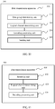
- FIG. 1 is a schematic flowchart of a data transmission method 100 according to an embodiment of the present invention from a perspective of a transmit end device. As shown in FIG. 1 , the method 100 includes:
- the data transmission method 100 is mainly completed at the physical layer of the transmit end device. That is, when the physical layer receives a plurality of MAC layer data frames that comes from the MAC layer, the foregoing method 100 is executed to convert MAC layer data into physical layer data that complies with a format of data transmitted between Ethernet devices and to transmit the physical layer data.
- the physical layer includes a reconciliation sublayer and a physical coding sublayer.
- the reconciliation sublayer is used to perform conversion processing on data between a MAC layer and the physical layer.
- the physical coding sublayer which includes N logical channels is used to implement encoding processing on physical layer data.
- the physical layer further includes a media independent interface.
- the media independent interface is arranged between the reconciliation sublayer and the physical coding sublayer and used for data transmission between the reconciliation sublayer and the physical coding sublayer by using N timeslots, where one timeslot is used to transmit data in one logical channel.
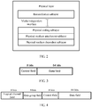
- FIG. 2 is a schematic diagram of a physical layer structure according to an embodiment of the present invention.
- a physical layer of an Ethernet device may include: a reconciliation sublayer (RS), a physical coding sublayer (PCS), a media independent interface (MII), a physical medium attachment (PMA) sublayer, and a physical medium dependent (PMD) sublayer.
- the reconciliation sublayer is used to perform reconciliation processing, convert an Ethernet frame (also known as a MAC layer data frame) into media independent interface data (an example of MAC layer data), and send the media independent interface data to the physical coding sublayer through the media independent interface.
- an Ethernet frame also known as a MAC layer data frame
- media independent interface data an example of MAC layer data
- the physical coding sublayer performs encoding processing (for example, 64B/66B encoding), scrambling processing, and the like on the media independent interface data to generate a (for example, 66B) code block (an example of physical layer data), and delivers the code block to a logical channel.
- the physical medium attachment sublayer is used to implement multiplexing from a logical channel to a physical channel.
- the physical medium dependent sublayer is used to transmit the physical layer data through a physical channel.
- an Ethernet frame from the MAC layer may be converted into data (that is, MAC layer data) that complies with physical layer data transmission, where the MAC layer data may include 8 bits of control information and 64 bits of data.
- FIG. 3 is a schematic diagram of a data format of media independent interface data (that is, MAC layer data) according to an embodiment of the present invention.
- MAC layer data may include a control field and a data field. The control field is used to carry 8 bits of control information and the data field is used to carry 64 bits of data.
- grouping processing may be performed on MAC layer data.
- grouping method for example, MAC layer data may be divided by destination address, and MAC layer data with a same destination address is added to a same group.
- upper-layer data may be grouped (for example, by data type) at an upper layer (a layer above the MAC layer) in advance, and an Ethernet frame generated according to the grouped upper-layer data are sent to the physical layer in different time segments that are preset.
- MAC layer data converted from the Ethernet frame received within a same time segment may be added to a same group; or grouping may be performed according to a rule preset by an administrator or a group identifier added to the Ethernet frame (the group identifier indicates a group to which MAC layer data converted from the Ethernet frame belongs).
- the group identifier may be added at the MAC layer or an upper layer (a layer above the MAC layer) according to, for example, a service to which the data belongs.
- Ethernet frame may also be grouped first, and then format conversion processing is performed on the Ethernet frame by taking a group as a unit to directly obtain MAC layer data groups.
- bandwidth (target bandwidth) required by each MAC layer data group may be determined.
- the target bandwidth of each MAC layer data group may be determined according to a transmission rate of the MAC layer data group (that is, an amount of data of the MAC layer data group, which is received or sent within a unit time).
- the target bandwidth of each MAC layer data group may also be determined according to a bandwidth identifier added to an Ethernet frame (the bandwidth identifier indicates bandwidth required by MAC layer data converted from the Ethernet frame).
- the bandwidth identifier may be added at an upper layer (a layer above the MAC layer) according to, for example, a maximum bandwidth requirement of the data.
- a logical channel may be allocated to each MAC layer data group.
- this process may be implemented at the reconciliation sublayer (that is, case 1), or may be implemented at the physical coding sublayer (that is, case 2). The following describes the foregoing two cases separately.
- the allocating, according to target bandwidth required by a target MAC layer data group and preset reference bandwidth of a logical channel, at least one target logical channel to the target MAC layer data group includes:
- MAC layer data group A an example of the target MAC layer data group
- MAC layer data group B another example of the target MAC layer data group
- MAC layer data group Z still another example of the target MAC layer data group
- a traffic bandwidth requirement (target bandwidth) of the MAC layer data group A is 50 G
- a traffic bandwidth requirement (target bandwidth) of the MAC layer data group B is 25 G
- a traffic bandwidth requirement (target bandwidth) of the MAC layer data group Z is 50 G.
- the MAC layer data group A corresponds to two logical channels (for example, a first logical channel and a second logical channel, which are referred to hereinafter as a logical channel 1 and a logical channel 2)
- the MAC layer data group B corresponds to one logical channel (for example, a third logical channel, which is referred to hereinafter as a logical channel 3)
- the MAC layer data group Z corresponds to two logical channels (for example, a fifteenth logical channel and a sixteenth logical channel, which are referred to hereinafter as a logical channel 15 and a logical channel 16).
- the reconciliation sublayer may send information (an example of the second indication information) indicating a logical channel corresponding to each piece of MAC layer data to the physical coding sublayer.
- the method further includes: sending, at the reconciliation sublayer, third indication information to the physical coding sublayer, where the third indication information is used to indicate the mapping relationship between the target MAC layer data group and the target logical channel.
- the reconciliation sublayer may send, to the physical coding sublayer, information (an example of the third indication information) used to indicate a MAC layer data group corresponding to each logical channel of the physical coding sublayer.
- the physical layer further includes a media independent interface.
- the media independent interface is arranged between the reconciliation sublayer and the physical coding sublayer and used for data transmission between the reconciliation sublayer and the physical coding sublayer by using N timeslots, where one timeslot is used to transmit data in one logical channel.
- data between the reconciliation sublayer and the physical coding sublayer is transmitted through the media independent interface.
- the media independent interface may use a time division multiplexing data transmission manner, that is, one period may be divided into N timeslots and the N timeslots correspond to N logical channels of the physical coding sublayer, that is, the media independent interface may transmit MAC layer data corresponding to only one logical channel in one timeslot.
- the first 8 bits of control information and 64 bits of data are placed in the first timeslot
- the second 8 bits of control information and 64 bits of data are placed in the second timeslot
- the third 8 bits of control information and 64 bits of data are placed in the first timeslot
- the fourth 8 bits of control information and 64 bits of data are placed in the second timeslot, and so on.
- the first 8 bits of control information and 64 bits of data are placed in the fifteenth timeslot
- the second 8 bits of control information and 64 bits of data are placed in the sixteenth timeslot
- the third 8 bits of control information and 64 bits of data are placed in the fifteenth timeslot
- the fourth 8 bits of control information and 64 bits of data are placed in the sixteenth timeslot, and so on.
- FIG. 4 is a schematic diagram of a data format of media independent interface data (that is, MAC layer data) according to another embodiment of the present invention.
- a logical channel field and a data group field may be added to a data format of MAC layer data.
- the logical channel field is used to carry second indication information indicating a logical channel corresponding to MAC layer data of a timeslot.
- the data group field is used to carry third indication information indicating a MAC layer data group to which the MAC layer data of the timeslot belongs.
- a logical channel field of the MAC layer data group A carries information indicating the first and second logical channels
- a data group field of the MAC layer data group A carries information indicating the data group A
- a logical channel field of the MAC layer data group B carries information indicating the third logical channel
- a data group field of the MAC layer data group B carries information indicating the data group B
- a logical channel field of the MAC layer data group Z carries information indicating the fifteenth and sixteenth logical channels
- a data group field of the MAC layer data group Z carries information indicating the data group Z.
- a sequence of the logical channel field and the data group field is not limited to that shown in FIG. 4 as long as the logical channel field and the data group field are carried in the data format of MAC layer data.
- the second indication information, the third indication information, and the MAC layer data may also be sent separately in different time segments; or a transmission rule may be specified in advance so that timeslots of the media independent interface correspond to logical channels of the physical coding sublayer one to one, so that the reconciliation sublayer may select time for transmission according to a mapping relationship between the timeslots and the logical channels, and therefore the physical coding sublayer may determine, according to a timeslot for receiving MAC layer data, a logical channel corresponding to the MAC layer data. Therefore, the foregoing logical channel field may be omitted.
- the physical coding sublayer may determine, according to the second indication information, MAC layer data (MAC layer data received in a same timeslot) corresponding to each logical channel, and may determine, according to the third indication information, one or more logical channels corresponding to each MAC layer data group.
- the foregoing data group field may be omitted, and the physical coding sublayer considers by default that the logical channels correspond to only one same MAC layer data group.
- target bandwidth of the MAC layer data group is less (less than or equal to reference bandwidth of a logical channel)
- the MAC layer data group corresponds to only one logical channel. Therefore, the foregoing logical channel field may be omitted, and the physical coding sublayer may randomly allocate a logical channel to the MAC layer data group.
- the allocating, according to target bandwidth required by a target MAC layer data group and preset reference bandwidth of a logical channel, at least one target logical channel to the target MAC layer data group includes:
- the method further includes: sending, at the reconciliation sublayer, third indication information to the physical coding sublayer, where the third indication information is used to indicate the mapping relationship between the target MAC layer data group and the target logical channel.
- the reconciliation sublayer may send, to the physical coding sublayer, information (an example of the third indication information) used to indicate a MAC layer data group corresponding to each logical channel of the physical coding sublayer.
- the physical layer further includes a media independent interface.
- the media independent interface is arranged between the reconciliation sublayer and the physical coding sublayer and used for data transmission between the reconciliation sublayer and the physical coding sublayer by using N timeslots, where one timeslot is used to transmit data in one logical channel.
- data between the reconciliation sublayer and the physical coding sublayer is transmitted through the media independent interface.
- the media independent interface may use a periodic data transmission manner, that is, one period may be divided into N timeslots and the N timeslots correspond to N logical channels of the physical coding sublayer, in other words, in one timeslot, the media independent interface may transmit MAC layer data corresponding to only one logical channel.
- the first 8 bits of control information and 64 bits of data are placed in the first timeslot
- the second 8 bits of control information and 64 bits of data are placed in the second timeslot
- the third 8 bits of control information and 64 bits of data are placed in the first timeslot
- the fourth 8 bits of control information and 64 bits of data are placed in the second timeslot, and so on.
- the first 8 bits of control information and 64 bits of data are placed in the fifteenth timeslot
- the second 8 bits of control information and 64 bits of data are placed in the sixteenth timeslot
- the third 8 bits of control information and 64 bits of data are placed in the fifteenth timeslot
- the fourth 8 bits of control information and 64 bits of data are placed in the sixteenth timeslot, and so on.
- FIG. 4 is a schematic diagram of a data format of media independent interface data (that is, MAC layer data) according to another embodiment of the present invention.
- a data group field may be added to a data format of MAC layer data.
- the data group field is used to carry third indication information indicating a MAC layer data group to which MAC layer data of a timeslot belongs.
- a target logical channel corresponding to each MAC layer data group is not determined at the RS layer, and therefore, a "logical channel field" shown in FIG. 4 is not required in this embodiment, that is, the data format of media independent interface data (that is, MAC layer data) in this embodiment may include only the data group field, a control field, and a data field that are shown in FIG. 4 .
- the physical coding sublayer may allocate, according to a timeslot for receiving each piece of MAC layer data, one same logical channel to MAC layer data received in a same timeslot, and therefore may determine, according to the third indication information, one or more logical channels corresponding to each MAC layer data group.
- the foregoing method for transmitting the third indication information is described merely as an example, and the present invention is not limited thereto.
- the third indication information and the MAC layer data may be sent separately in different time segments.
- the foregoing data group field may be omitted, and the physical coding sublayer considers by default that the logical channels correspond to only one same MAC layer data group.
- target bandwidth of the MAC layer data group is less (less than or equal to reference bandwidth of a logical channel)
- the MAC layer data group corresponds to only one logical channel. Therefore, the foregoing logical channel field may be omitted, and the physical coding sublayer may randomly allocate a logical channel to the MAC layer data group.
- encoding processing may be performed on data (a stream of 8 + 64 bits information) of each logical channel.
- the following method may be used as an example:
- 64B/66B encoding may be performed on the stream of 8 + 64 bits information (information in a control field and a data field) to form a 66B code block stream.
- FEC forward error correction
- encoding and compression processing may be performed again on 66B code blocks selectively, for example, every four 66B code blocks are encoded and converted into one 257B code block, and then FEC processing is performed on a 257B code block stream.
- scrambling processing may be performed on a code block stream into which FEC check information is added.
- FEC check information For a 66B code block, a 2-bit synchronization header may not be involved in the scrambling processing.
- processes and methods of 64B/66B encoding processing, FEC processing, and scrambling processing may be the same as those in the prior art, and are not described herein to avoid repetition.
- the performing encoding processing on the target MAC layer data group according to the target logical channel to generate target physical layer data is specifically:
- 64B/66B encoding processing, FEC processing, and scrambling processing may be performed on the MAC layer data by taking a logical channel as a unit. In this case, it needs to be ensured that processing of logical channels corresponding to a same MAC layer data group is synchronized.
- overall 64B/66B encoding processing, FEC processing, and scrambling processing may be performed on code block streams of logical channels corresponding to a same MAC layer data group by taking a MAC layer data group as a unit.
- Performing encoding, FEC processing, and scrambling processing by taking a logical channel or a MAC data group as a unit can implement multi-channel processing and lower complexity of transmitting a high-rate service, thereby reducing hardware costs.
- an alignment marker may be inserted by taking a logical channel or a MAC layer data group as a unit.
- the AM is inserted based on a certain period, where the period is 16384 code blocks on each logical channel.
- Respective alignment markers are periodically inserted on logical channels, or respective alignment markers are inserted on logical channels within a MAC layer data group at a same time and the insertion is performed periodically on MAC layer data groups.
- the AM is a special pattern. Alignment marker AM patterns inserted on logical channels are different and used for a receive end to differentiate the logical channels.
- a logical channel number can be identified by using a pattern of an alignment marker code block.
- data that complies with physical layer data transmission is generated. That is, by means of the foregoing process, physical layer data A corresponding to the foregoing MAC layer data group A, physical layer data B corresponding to the foregoing MAC layer data group B, and physical layer data C corresponding to the foregoing MAC layer data group C are generated.
- the method further includes: sending the first indication information to the target receive end device, where the first indication information is used to indicate the mapping relationship between the target MAC layer data group and the target logical channel.
- the first indication information and the target physical layer data are carried in a same data packet; or the first indication information is sent independent of the target physical layer data.
- the transmit end device further needs to notify (by the first indication information) a receive end of a MAC layer data group corresponding to each logical channel.
- logical port identifier (LPID) information may be added to the foregoing added AM.
- LPID information added to logical channels corresponding to a same MAC layer data group is consistent, and LPID information added to logical channels corresponding to different MAC layer data groups varies. Therefore, the receive end device can differentiate a MAC layer data group corresponding to each logical channel by identifying LPID information of the logical channel.
- a 66B alignment marker code block is used as an example.
- Table 1 shows a 66B alignment marker according to an embodiment of the present invention.
- one AM may have 66 bits.
- Block synchronization header information 10 is placed in the first two bits, and the foregoing first indication information is placed in the LPID2 field and the LPID6 field.
- information obtained by reversing bits in the LPID2 field is placed in the LPID6 field.
- Check information of the logical channel is placed in the BIP3 field and the BIP7 field. Alignment pattern information of a logical channel is placed in the M0 field, M1 field, M4 field and M5 field.
- the foregoing method for transmitting the first indication information is described merely as an example, and the present invention is not limited thereto.
- the first indication information and the AM may be sent separately in different time segments.
- the foregoing LPID2 field and LPID6 field may be omitted, and the receive end considers by default that the logical channels correspond to only one same MAC layer data group.
- a transmit end device sends to a receive end device information indicating physical layer data (or each MAC layer data group) corresponding to each logical channel, which can enable a receive end device to easily determine logical channels corresponding to a same MAC layer data group.
- the physical medium attachment sublayer may multiplex to one or more physical channels the foregoing determined data corresponding to each logical channel.
- different MAC layer data groups (or physical layer data) may be multiplexed to different physical channels.
- one MAC layer data group may correspond to one or more physical channels.
- the transmit end device has a total of four physical channels and each channel has bandwidth of 100 G.
- the logical channel 1 and the logical channel 2 corresponding to the MAC layer data group A may be multiplexed to one physical channel (for example, a physical channel 1).
- the logical channel 3 corresponding to the MAC layer data group B may be multiplexed to one physical channel (for example, a physical channel 2).
- the logical channel 15 and the logical channel 16 corresponding to the MAC layer data group Z may be multiplexed to one physical channel (for example, a physical channel 3).
- a multiplexing manner may be bit multiplexing.
- the number of logical channels may be an integer multiple of the number of physical channels, or reference bandwidth of a physical channel may be an integer multiple of reference bandwidth of a logical channel.
- reference bandwidth of a physical channel may be set by setting reference bandwidth of a physical channel to reference bandwidth of a logical channel, transmission on a same group of logical channels may be implemented by using a same physical channel.
- a multi-carrier manner may be used to transmit to the receive end device the foregoing physical layer data that is multiplexed to each physical channel.
- the sending the target physical layer data to a target receive end device of at least one receive end device includes:
- one or more logical ports may be divided at the physical layer (specifically, the physical medium dependent sublayer), where one logical port may include one or more physical channels and physical channels included in different logical ports are different.
- the numbers of physical channels included in different logical ports may be the same or may be different, and the present invention poses no particular limitation thereon. It should be understood that the foregoing logical port dividing method is described merely as an example, and the present invention is not limited thereto.
- logical ports may also be divided based on the foregoing determined MAC layer data groups, so that one logical port corresponds to one MAC layer data group, or one logical port corresponds to a plurality of logical channels corresponding to a same MAC layer data group.
- a plurality of logical channels corresponding to a same logical port is multiplexed to at least one physical channel that belongs to the logical port.
- the transmit end device may connect to only one receive end device.
- the transmit end device may select, according to a rate requirement of the physical layer data (or target bandwidth of a corresponding MAC layer data group), reference bandwidth of each physical channel, and the number of physical channels included in each logical port, one logical port to perform the sending. For example, if the rate requirement of the physical layer data is 75 G and bandwidth of one physical channel is 25 G, a logical port including three physical channels may be selected to send the physical layer data.
- the transmit end device is communicatively connected to at least two receive end devices, and the transmit end device includes at least two logical ports, where one logical port corresponds to one receive end device.
- the transmit end device may allocate a plurality of physical channels to a plurality of logical ports, and one logical port may correspond to only one receive end device, that is, the logical port is only used to transmit data that needs to be sent to the receive end device. It should be noted that, in this embodiment of the present invention, for one receive end device, there may be a plurality of corresponding logical interfaces or there may be only one corresponding logical interface, and the present invention poses no particular limitation thereon.
- the determining, from at least one logical port, a target logical port that is used to transmit the target physical layer data includes: determining, from a preset mapping relationship between the at least two receive end devices and the at least two logical ports, the target logical port according to the target receive end device.
- the transmit end device may determine a logical port according to the mapping relationship between the logical ports and the receive end devices. As shown in FIG. 7 , physical layer data A (an example of target physical layer data) generated by a MAC layer data group A needs to be sent to a receive end device A; and then, a logical port A (an example of the target logical port) corresponding to the receive end device A may be selected and a physical channel corresponding to the logical port A is used to perform the sending.
- physical layer data A an example of target physical layer data
- a logical port A an example of the target logical port
- Physical layer data B (another example of the target physical layer data) generated by a MAC layer data group B needs to be sent to a receive end device B; and then, a logical port B (another example of the target logical port) corresponding to the receive end device B may be selected and a physical channel corresponding to the logical port B is used to perform the sending.
- Physical layer data Z (still another example of the target physical layer data) generated by a MAC layer data group Z needs to be sent to a receive end device Z; and then, a logical port Z (still another example of the target logical port) corresponding to the receive end device Z may be selected and a physical channel corresponding to the logical port Z is used to perform the sending.
- bandwidth of each logical port may be pre-determined according to a transmission rate supported by each receive end device, and a rate requirement (target bandwidth) of data that needs to be sent to a receive end device needs to be lower than the transmission rate supported by each receive end device, thereby ensuring that bandwidth of a selected logical port is greater than or equal to the rate requirement of the data that needs to be transmitted.
- the transmit end device may search a prestored mapping relationship between MAC layer addresses and the receive end devices, for example, a forwarding table, according to a destination MAC layer address of a MAC layer data group, to determine a receive end device to which each MAC layer data group (or target physical layer data generated after encoding processing is performed on the MAC layer data group) needs to be sent.
- a prestored mapping relationship between MAC layer addresses and the receive end devices for example, a forwarding table, according to a destination MAC layer address of a MAC layer data group, to determine a receive end device to which each MAC layer data group (or target physical layer data generated after encoding processing is performed on the MAC layer data group) needs to be sent.
- Optical carrier scheduling may also be considered to schedule a plurality of MAC layer data groups to different destinations. As shown in FIG. 7
- a physical port of a transmit end device may include a logical port A, a logical port B, and a logical port Z, where a service carried on the logical port A is transmitted by using a subcarrier A, a service carried on the logical port B is transmitted by using a subcarrier B, and a service carried on the logical port Z is transmitted by using a subcarrier Z, and the logical ports A, B, and Z are connected to a cross-connect node by using a same optical fiber (specifically, the subcarrier A, the subcarrier B, and the subcarrier Z).
- the cross-connect node may be a wavelength cross-connect processing node and may schedule a plurality of subcarriers to different directions.
- the subcarrier A, the subcarrier B, and the subcarrier Z are scheduled to a receive end device A, a receive end device B, and a receive end device Z respectively.
- a configuration command may be delivered by a network management system in advance to determine a scheduling direction of each subcarrier, that is, it may be specified by the network management system in advance that the subcarrier A, the subcarrier B, and the subcarrier Z are scheduled to the receive end device A, the receive end device B, and the receive end device Z respectively.
- a plurality of physical channels is divided at a same time to form a plurality of logical ports, so that data can be sent to different receive end devices through different ports, which can implement point-to-multipoint data transmission, thereby communication flexibility of an Ethernet communications system is greatly improved.
- optical carrier scheduling is used, which, compared with the prior art, which can put an optical subcarrier that is temporarily unneeded to sleep or disable the optical subcarrier, thereby reducing power consumption and saving energy.
- the number of physical channels included in each logical port varies, which can adapt one Ethernet device to data transmission with a plurality of rate requirements, thereby improving adaptability and communication flexibility of the Ethernet device and saving device costs.
- a receive end device may process, at the physical layer, the physical layer data to acquire MAC layer data.
- a physical layer of an Ethernet device (the receive end device) in this embodiment of the present invention may include: a reconciliation sublayer, a physical coding sublayer, a media independent interface, a physical medium attachment sublayer, and a physical medium dependent sublayer.
- the physical medium dependent sublayer is used to receive, through a physical channel, physical layer data sent by a transmit end.
- the physical medium attachment sublayer is used to implement demultiplexing from a physical channel to a logical channel.
- the physical coding sublayer is used to deliver physical layer data to a logical channel and perform decoding processing (for example, 64B/66B decoding), descrambling processing, and the like on the physical layer data to generate media independent interface data.
- the reconciliation sublayer is used to perform reconciliation processing and convert media independent interface data into an Ethernet frame.
- the receive end device may demultiplex the physical channel to restore all physical layer data.
- a logical channel corresponding to each piece of physical layer data may be determined, and the physical layer data is processed according to the logical channel to acquire MAC layer data.
- code block synchronization header searching processing may be performed for each logical channel to determine a code block border; alignment marker locking processing is performed on each logical channel and an alignment marker code block is identified by means of comparison with an AM pattern; alignment and re-sorting processing are performed based on each logical channel to restore an original code block stream; and descrambling processing, FEC processing, and 64B/66B decoding processing are separately performed on each logical channel; these processes are reverse to those in the sending direction.
- 64B/66B decoding processing an original stream of 8 bits of control information and 64 bits of data information is formed, and Flex MII interface data is further formed.
- the Flex MII interface data may be converted into an Ethernet frame that needs to be sent to the MAC layer.
- the receive end device in a case in which the physical layer data is generated after the transmit end device performs processing such as encoding on a plurality of MAC layer data groups, the receive end device further needs to determine a MAC layer data group corresponding to each logical channel.
- the transmit end may add an LPID field to an AM to carry the first indication information. Therefore, the receive end device may extract and compare LPIDs in AMs of the logical channels to determine the MAC layer data groups (or a combination manner of the logical channels) corresponding to the logical channels. As shown in FIG.
- grouping is performed on MAC layer data and a logical channel is allocated to each MAC layer data group according to a rate of each MAC layer data group, to perform encoding processing and transmission processing on each MAC layer data group according to the allocated logical channel, which can meet a requirement for an Ethernet network with diversified rate levels and implement interconnection between Ethernet interfaces of different rate levels.
- a logical channel is allocated according to bandwidth required by a MAC layer data group, which, compared with the prior art, can put a logical channel that is temporarily unneeded to sleep or disable the logical channel when a bandwidth requirement of MAC layer data is low, thereby reducing power consumption and saving energy.
- FIG. 9 is a schematic flowchart of a data transmission method 200 according to an embodiment of the present invention from a perspective of a receive end device. As shown in FIG. 9 , the method 200 includes:
- the receive end device may receive the target physical layer data, where the target physical layer data may be generated and sent in the following manner by the target transmit end device that is communicatively connected to the receive end device, that is: when receiving a plurality of MAC layer data frames that come from the MAC layer, a physical layer of the target transmit end device may covert the MAC layer data into physical layer data that complies with a format of data transmitted between Ethernet devices.
- the target transmit end device may convert, at a reconciliation sublayer, Ethernet frames that come from the MAC layer into data (that is, MAC layer data) that complies with physical layer data transmission, where the MAC layer data may include 8 bits (bit) of control information and 64 bits of data.
- MAC layer data may include a control field and a data field. The control field is used to carry 8 bits of control information and the data field is used to carry 64 bits of data.
- the target transmit end device may perform grouping processing on MAC layer data.
- grouping processing for example, MAC layer data may be divided by destination address, and MAC layer data with a same destination address is added to a same group.
- the target transmit end device may determine bandwidth (target bandwidth) required by each MAC layer data group.
- the target bandwidth of each MAC layer data group may be determined according to a transmission rate of the MAC layer data group (that is, an amount of data of the MAC layer data group, which is received or sent within a unit time).
- the target transmit end device may allocate a logical channel to each MAC layer data group.
- this process may be implemented at the reconciliation sublayer, or may be implemented at a physical coding sublayer.
- MAC layer data group A an example of the target MAC layer data group
- MAC layer data group B another example of the target MAC layer data group
- MAC layer data group Z still another example of the target MAC layer data group
- a traffic bandwidth requirement (target bandwidth) of the MAC layer data group A is 50 G
- a traffic bandwidth requirement (target bandwidth) of the MAC layer data group B is 25 G
- a traffic bandwidth requirement (target bandwidth) of the MAC layer data group Z is 50 G.
- the target transmit end device may determine that the MAC layer data group A corresponds to two logical channels (for example, a first logical channel and a second logical channel, which are referred to hereinafter as a logical channel 1 and a logical channel 2), the MAC layer data group B corresponds to one logical channel (for example, a third logical channel, which is referred to hereinafter as a logical channel 3), and the MAC layer data group Z corresponds to two logical channels (for example, a fifteenth logical channel and a sixteenth logical channel, which are referred to hereinafter as a logical channel 15 and a logical channel 16).
- a first logical channel and a second logical channel which are referred to hereinafter as a logical channel 1 and a logical channel 2
- the MAC layer data group B corresponds to one logical channel (for example, a third logical channel, which is referred to hereinafter as a logical channel 3)
- the MAC layer data group Z corresponds to
- the reconciliation sublayer may send information (an example of second indication information) indicating a logical channel corresponding to each piece of MAC layer data to the physical coding sublayer.
- the reconciliation sublayer may send, to the physical coding sublayer, information (an example of third indication information) used to indicate a MAC layer data group corresponding to each logical channel of the physical coding sublayer.
- data between the reconciliation sublayer and the physical coding sublayer may be transmitted through a media independent interface.
- the media independent interface may use a time division multiplexing data transmission manner, that is, one period may be divided into N timeslots and the N timeslots correspond to N logical channels of the physical coding sublayer, in other words, in one timeslot, the media independent interface may transmit MAC layer data corresponding to only one logical channel .
- the media independent interface may transmit MAC layer data corresponding to only one logical channel .
- the first 8 bits of control information and 64 bits of data are placed in the first timeslot
- the second 8 bits of control information and 64 bits of data are placed in the second timeslot
- the third 8 bits of control information and 64 bits of data are placed in the first timeslot
- the fourth 8 bits of control information and 64 bits of data are placed in the second timeslot, and so on.
- the second indication information and the third indication information may be included in MAC layer data and transmitted to the physical coding sublayer at a same time.
- FIG. 4 is a schematic diagram of a data format of media independent interface data (that is, MAC layer data) according to another embodiment of the present invention.
- a logical channel field and a data group field may be added to a data format of MAC layer data.
- the logical channel field is used to carry second indication information indicating a logical channel corresponding to MAC layer data of a timeslot.
- the data group field is used to carry third indication information indicating a MAC layer data group to which the MAC layer data of the timeslot belongs.
- the target transmit end device may determine, according to the second indication information, MAC layer data (MAC layer data received in a same timeslot) corresponding to each logical channel, and may determine, according to the third indication information, one or more logical channels corresponding to each MAC layer data group.
- MAC layer data MAC layer data received in a same timeslot
- the target transmit end device may determine at the reconciliation sublayer that the MAC layer data group A corresponds to two logical channels, the MAC layer data group B corresponds to one logical channel, and the MAC layer data group Z corresponds to two logical channels.
- the reconciliation sublayer may send, to the physical coding sublayer, information (an example of third indication information) used to indicate a MAC layer data group corresponding to each logical channel of the physical coding sublayer.
- data between the reconciliation sublayer and the physical coding sublayer is transmitted through a media independent interface.
- the media independent interface may use a time division multiplexing (or periodic) data transmission manner, that is, one period may be divided into N timeslots and the N timeslots correspond to N logical channels of the physical coding sublayer, in other words, the media independent interface may transmit MAC layer data corresponding to only one logical channel in one timeslot.
- the media independent interface may transmit MAC layer data corresponding to only one logical channel in one timeslot.
- the first 8 bits of control information and 64 bits of data are placed in the first timeslot
- the second 8 bits of control information and 64 bits of data are placed in the second timeslot
- the third 8 bits of control information and 64 bits of data are placed in the first timeslot
- the fourth 8 bits of control information and 64 bits of data are placed in the second timeslot, and so on.
- FIG. 4 is a schematic diagram of a data format of media independent interface data (that is, MAC layer data) according to another embodiment of the present invention. As shown in FIG.
- a data group field may be added to a data format of MAC layer data.
- the data group field is used to carry third indication information indicating a MAC layer data group to which MAC layer data of the timeslot belongs. Therefore, at the physical coding sublayer, the target transmit end device may allocate, according to a received timeslot of each piece of MAC layer data, a same logical channel to MAC layer data received within a same timeslot, and therefore may determine, according to the third indication information, one or more logical channels corresponding to each MAC layer data group.
- the target transmit end device may perform encoding processing on data (a stream of 8 + 64 bits information) of each logical channel. For example, first, 64B/66B encoding may be performed on the stream of 8 + 64 bits information (information in a control field and a data field) to form a 66B code block stream; after that, forward error correction (FEC, Forward Error Correction) processing may be performed on the 66B code block stream; or encoding and compression processing may be performed again on 66B code blocks selectively, for example, every four 66B code blocks are encoded and converted into one 257B code block, and then FEC processing is performed on a 257B code block stream; and finally, scrambling processing may be performed on a code block stream into which FEC check information is added.
- FEC Forward Error Correction
- a 2-bit synchronization header may not be involved in the scrambling processing.
- 64B/66B encoding processing, FEC processing, and scrambling processing may be performed on the MAC layer data by taking a logical channel as a unit. In this case, it needs to be ensured that processing of logical channels corresponding to a same MAC layer data group is synchronized.
- overall 64B/66B encoding processing, FEC processing, and scrambling processing may be performed on code block streams of logical channels corresponding to a same MAC layer data group by taking a MAC data group as a unit.
- an alignment marker may be inserted by taking a MAC layer data group as a unit.
- the AM is inserted based on a certain period, where the period is 16384 code blocks on each logical channel.
- Respective alignment markers are inserted on logical channels within a MAC layer data group at a same time and the insertion is performed periodically on MAC layer data groups.
- the AM is a special pattern. Alignment marker AM patterns inserted on logical channels are different and used for a receive end to differentiate the logical channels. A logical channel number can be identified by using a pattern of an alignment marker code block.
- data that complies with physical layer data transmission is generated. That is, by means of the foregoing process, physical layer data A corresponding to the foregoing MAC layer data group A, physical layer data B corresponding to the foregoing MAC layer data group B, and physical layer data C corresponding to the foregoing MAC layer data group C are generated.
- the target transmit end device may multiplex to one or more physical channels the foregoing determined data corresponding to each logical channel.
- different MAC layer data groups (or physical layer data) may be multiplexed to different physical channels.
- one MAC layer data group may correspond to one or more physical channels.
- the target transmit end device has a total of four physical channels and each channel has bandwidth of 100 G.
- the logical channel 1 and the logical channel 2 corresponding to the MAC layer data group A may be multiplexed to one physical channel (for example, a physical channel 1).
- the logical channel 3 corresponding to the MAC layer data group B may be multiplexed to one physical channel (for example, a physical channel 2).
- the logical channel 15 and the logical channel 16 corresponding to the MAC layer data group Z may be multiplexed to one physical channel (for example, a physical channel 3).
- a multiplexing manner may be bit multiplexing.
- the target transmit end device may use a multi-carrier manner to transmit to the receive end device the foregoing physical layer data (including the target physical layer data) that is multiplexed to each physical channel.
- the receive end device may receive, through a physical channel, the target physical layer data sent by the target transmit end device.
- the receive end device may demultiplex the physical channel to restore all physical layer data. It should be noted that, in this embodiment of the present invention, in a case in which the physical layer data is generated after the target transmit end device performs processing such as encoding on a plurality of MAC layer data groups, the receive end device further needs to determine a MAC layer data group corresponding to each logical channel. That is:
- the determining, from N logical channels, at least one target logical channel that corresponds to only the target physical layer data includes:
- the first indication information and the target physical layer data are carried in a same data packet; or the first indication information is sent independent of the target physical layer data.
- a target transmit end device acquires a plurality of MAC layer data groups (the MAC layer data group A, the MAC layer data group B, and the MAC layer data group Z), the target transmit end device further needs to notify (by the first indication information) a receive end device of a MAC layer data group corresponding to each logical channel.
- logic port identifier LPID, Logic Port Identifier
- LPID information added to logical channels corresponding to a same MAC layer data group is consistent, and LPID information added to logical channels corresponding to different MAC layer data groups varies.
- the receive end device can differentiate a MAC layer data group corresponding to each logical channel by identifying LPID information of the logical channel.
- a 66B alignment marker code block is used as an example. As shown in Table 1, there are a total of 66 bits. Block synchronization header information 10 is placed in the first two bits, and the foregoing first indication information is placed in the LPID2 field and the LPID6 field. Information obtained by reversing bits in the LPID2 field is placed in the LPID6 field. Check information of the logical channel is placed in the BIP3 field and the BIP7 field. Alignment pattern information of a logical channel is placed in the M0 field, M1 field, M4 field and M5 field.
- An LPID field may be added to an AM to carry the first indication information. Therefore, the receive end device may extract and compare LPIDs in AMs of the logical channels to determine the MAC layer data groups (or a combination manner of the logical channels) corresponding to the logical channels.
- the foregoing method for transmitting the first indication information is described merely as an example, and the present invention is not limited thereto.
- the first indication information and the AM may be sent separately in different time segments.
- the foregoing LPID2 field and LPID6 field may be omitted, and the receive end considers by default that the logical channels correspond to only one same MAC layer data group.
- the physical layer includes a reconciliation sublayer and a physical coding sublayer; the determining, from N logical channels according to the first indication information, at least one target logical channel that corresponds to only a target MAC layer data group includes:
- the receive end device may perform code block synchronization header searching processing separately for each logical channel to determine a code block border; perform alignment marker locking processing on each logical channel and identify an alignment marker code block by means of comparison with an AM pattern; based on each logical channel, perform alignment and re-sorting processing to restore an original code block stream; and perform descrambling processing, FEC processing, and 64B/66B decoding processing separately on each logical channel; these processes are reverse to those in the sending direction.
- the 64B/66B decoding processing an original stream of 8 bits of control information and 64 bits of data information is formed, and Flex MII interface data is further formed.
- the Flex MII interface data may be converted into an Ethernet frame that needs to be sent to the MAC layer.
- the physical layer further includes a media independent interface, where the media independent interface is arranged between the reconciliation sublayer and the physical coding sublayer and used for data transmission between the reconciliation sublayer and the physical coding sublayer by using N timeslots, where one timeslot is used to transmit data in one logical channel; and the sending, at the physical coding sublayer, the target MAC layer data group to the reconciliation sublayer according to the target logical channel includes:
- data between the reconciliation sublayer and the physical coding sublayer may be transmitted through the media independent interface.
- the media independent interface may use a time division multiplexing data transmission manner, that is, one period may be divided into N timeslots and the N timeslots correspond to N logical channels of the physical coding sublayer, that is, the media independent interface may transmit MAC layer data corresponding to only one logical channel in one timeslot.
- the first 8 bits of control information and 64 bits of data are placed in the first timeslot
- the second 8 bits of control information and 64 bits of data are placed in the second timeslot
- the third 8 bits of control information and 64 bits of data are placed in the first timeslot
- the fourth 8 bits of control information and 64 bits of data are placed in the second timeslot, and so on.
- the first 8 bits of control information and 64 bits of data are placed in the fifteenth timeslot
- the second 8 bits of control information and 64 bits of data are placed in the sixteenth timeslot
- the third 8 bits of control information and 64 bits of data are placed in the fifteenth timeslot
- the fourth 8 bits of control information and 64 bits of data are placed in the sixteenth timeslot, and so on.
- the performing decoding processing on the target physical layer data according to the target logical channel to acquire the target MAC layer data group includes:
- the physical coding sublayer may send, to the reconciliation sublayer, information used to indicate a MAC layer data group corresponding to each logical channel of the physical coding sublayer (an example of the third indication information). Therefore, the reconciliation sublayer may determine, according to the second indication information, MAC layer data (MAC layer data received in a same timeslot) corresponding to each logical channel, and may determine, according to the third indication information, one or more logical channels corresponding to each I MAC layer data group.
- the reconciliation sublayer may determine, according to the second indication information, MAC layer data (MAC layer data received in a same timeslot) corresponding to each logical channel, and may determine, according to the third indication information, one or more logical channels corresponding to each I MAC layer data group.
- one or more logical ports may be divided at the physical layer (specifically, the physical medium dependent sublayer), where one logical port may include one or more physical channels and physical channels included in different logical ports are different.
- the numbers of physical channels included in different logical ports may be the same or may be different, and the present invention poses no particular limitation thereon.
- the receive end device may allocate a plurality of physical channels to a plurality of logical ports, and one logical port may correspond to only one transmit end device, that is, the logical port is only used to transmit data that comes from the transmit end device.
- one transmit end device may have a plurality of corresponding logical interfaces or may have only one corresponding logical interface, and the present invention poses no particular limitation thereon.
- a plurality of physical channels is divided to form a plurality of logical ports, so that data sent by different transmit end devices can be received through different ports, which can implement point-to-multipoint data transmission, thereby greatly improving communication flexibility of an Ethernet communications system.
- the number of physical channels included in each logical port varies, which can adapt one Ethernet device to data transmission with a plurality of rate requirements, thereby improving adaptability and communication flexibility of the Ethernet device and saving device costs.
- grouping is performed on MAC layer data and a logical channel is allocated to each MAC layer data group according to a rate of each MAC layer data group, to perform encoding processing and transmission processing on each MAC layer data group according to the allocated logical channel, which can meet a requirement for an Ethernet network with diversified rate levels and implement interconnection between Ethernet interfaces of different rate levels.
- a logical channel is allocated according to bandwidth required by a MAC layer data group, which, compared with the prior art, can put a logical channel that is temporarily unneeded to sleep or disable the logical channel when a bandwidth requirement of MAC layer data is low, thereby reducing power consumption and saving energy.
- FIG. 10 is a schematic block diagram of a data transmission apparatus 300 according to an embodiment of the present invention. As shown in FIG. 10 , the apparatus 300 includes:
- the sending unit 340 is specifically configured to determine a target logical port from at least one logical port, where one logical port corresponds to at least one physical channel; and send the target physical layer data to the target receive end device through a physical channel corresponding to the target logical port.
- the data transmission apparatus 300 is communicatively connected to at least two receive end devices, and the data transmission apparatus 300includes at least two logical ports, where one logical port corresponds to one receive end device; and the sending unit 340 is specifically configured to determine, from a preset mapping relationship between the at least two receive end devices and the at least two logical ports, the target logical port according to the target receive end device.
- the physical layer includes a reconciliation sublayer and a physical coding sublayer
- the logical channel determining unit 320 is specifically configured to determine, at the reconciliation sublayer, the target logical channel according to the target bandwidth and the reference bandwidth, and send second indication information to the physical coding sublayer, where the second indication information is used to indicate the target logical channel
- the encoding processing unit 330 is specifically configured to determine, at the physical coding sublayer, the target logical channel according to the second indication information, and perform encoding processing on the target MAC layer data group according to the target logical channel.
- the physical layer includes a reconciliation sublayer, a media independent interface, and a physical coding sublayer, where the media independent interface is arranged between the reconciliation sublayer and the physical coding sublayer and used for data transmission between the reconciliation sublayer and the physical coding sublayer by using N timeslots, where one timeslot is used to transmit data in one logical channel; and the logical channel determining unit 320 is specifically configured to determine, at the reconciliation sublayer according to the target bandwidth and the reference bandwidth, the number of target logical channels and the number of target timeslots on the media independent interface which are used to transmit the target MAC layer data group; send, on the media independent interface, the target MAC layer data group to the physical coding sublayer by using the target timeslots; and allocate, at the physical coding sublayer, a logical channel to the target MAC layer data group as the target logical channel according to the number of the target timeslots.
- the encoding processing unit 330 is specifically configured to perform, at the physical coding sublayer, encoding processing on the target MAC layer data group according to the target logical channel.
- the logical channel determining unit 320 is specifically configured to send, at the reconciliation sublayer, third indication information to the physical coding sublayer, where the third indication information is used to indicate the mapping relationship between the target MAC layer data group and the target logical channel.
- the encoding processing unit 330 is specifically configured to perform encoding processing on the target MAC layer data group by taking a target logical channel as a unit to generate the target physical layer data.
- the encoding processing unit 330 is specifically configured to take the at least one target logical channel corresponding to the target MAC layer data group as one group, and perform encoding processing on the target MAC layer data group by taking a group as a unit, to generate the target physical layer data.
- the first indication information and the target physical layer data are carried in a same data packet; or the first indication information is sent independent of the target physical layer data.
- the data transmission apparatus 300 may correspond to the transmit end device (or the target transmit end device) in the method in the embodiments of the present invention.
- the units, that is, the modules, in the data transmission apparatus 300 and the foregoing other operations and/or functions are intended to implement a corresponding procedure of the method 100 in FIG. 1 , which are not described herein again for brevity.
- grouping is performed on MAC layer data and a logical channel is allocated to each MAC layer data group according to a rate of each MAC layer data group, to perform encoding processing and transmission processing on each MAC layer data group according to the allocated logical channel, which can meet a requirement for an Ethernet network with diversified rate levels and implement interconnection between Ethernet interfaces of different rate levels.
- a logical channel is allocated according to bandwidth required by a MAC layer data group, which, compared with the prior art, can put a logical channel that is temporarily unneeded to sleep or disable the logical channel when a bandwidth requirement of MAC layer data is low, thereby reducing power consumption and saving energy.
- FIG. 11 is a schematic block diagram of a data transmission apparatus 400 according to an embodiment of the present invention. As shown in FIG. 11 , the apparatus 400 includes:
- the first indication information and the target physical layer data are carried in a same data packet; or the first indication information is sent independent of the target physical layer data.
- the physical layer includes a reconciliation sublayer and a physical coding sublayer;
- the logical channel determining unit 420 is specifically configured to determine, at the physical coding sublayer, the target logical channel from the N logical channels according to the first indication information;
- the decoding processing unit 430 is specifically configured to perform, at the physical coding sublayer, decoding processing on the target physical layer data according to the target logical channel to acquire the target MAC layer data group; and send, at the physical coding sublayer, the target MAC layer data group to the reconciliation sublayer according to the target logical channel, so that conversion between the physical layer and the MAC layer is performed on the target MAC layer data group at the reconciliation sublayer and data obtained after the conversion is sent to the MAC layer.
- the physical layer further includes a media independent interface, where the media independent interface is arranged between the reconciliation sublayer and the physical coding sublayer and used for data transmission between the reconciliation sublayer and the physical coding sublayer by using N timeslots, where one timeslot is used to transmit data in one logical channel; and the decoding processing unit 430 is specifically configured to determine, at the physical coding sublayer according to the target logical channel, a target timeslot that is on the media independent interface and used to transmit the target MAC layer data group; and send, on the media independent interface, the target MAC layer data group to the reconciliation sublayer by using the target timeslot, so that the target MAC layer data group is determined at the reconciliation sublayer according to the target timeslot.
- the media independent interface is arranged between the reconciliation sublayer and the physical coding sublayer and used for data transmission between the reconciliation sublayer and the physical coding sublayer by using N timeslots, where one timeslot is used to transmit data in one logical channel
- the decoding processing unit 430 is specifically configured to determine, at the physical coding sub
- the decoding processing unit 430 is specifically configured to perform, at the physical coding sublayer, decoding processing on the target physical layer data according to the target logical channel to acquire the target MAC layer data group; and send, at the physical coding sublayer, third indication information to the reconciliation sublayer, where the third indication information is used to indicate the mapping relationship between the target MAC layer data group and the target logical channel; and determine, at the reconciliation sublayer, the target MAC layer data group according to the third indication information.
- the decoding processing unit 430 is specifically configured to take the target logical channel corresponding to the target physical layer data as one group, and perform decoding processing on the target physical layer data group by taking a group as a unit, to generate the target MAC layer data group.
- the data transmission apparatus 400 may correspond to the receive end device (or the target receive end device) in the method in the embodiments of the present invention.
- the units, that is, the modules, in the data transmission apparatus 400 and the foregoing other operations and/or functions are intended to implement a corresponding procedure of the method 200 in FIG. 9 , which are not described herein again for brevity.
- grouping is performed on MAC layer data and a logical channel is allocated to each MAC layer data group according to a rate of each MAC layer data group, to perform encoding processing and transmission processing on each MAC layer data group according to the allocated logical channel, which can meet a requirement for an Ethernet network with diversified rate levels and implement interconnection between Ethernet interfaces of different rate levels.
- a logical channel is allocated according to bandwidth required by a MAC layer data group, which, compared with the prior art, can put a logical channel that is temporarily unneeded to sleep or disable the logical channel when a bandwidth requirement of MAC layer data is low, thereby reducing power consumption and saving energy.
- FIG. 12 is a schematic block diagram of a data transmission device 500 according to an embodiment of the present invention. As shown in FIG. 12 , the device 500 includes:
- the processor 520 invokes, through the bus 510, a program stored in the memory 530 to perform, at a physical layer, grouping processing on at least one piece of MAC layer data that comes from a MAC layer, to determine at least one MAC layer data group; allocate, according to target bandwidth required by a target MAC layer data group and preset reference bandwidth of a logical channel, at least one target logical channel from N logical channels to the target MAC layer data group, so that the target logical channel corresponds to only the target MAC layer data group; perform encoding processing on the target MAC layer data group according to the target logical channel to generate target physical layer data, where the target logical channel corresponds to only the target physical layer data; and control the transceiver 540 to send the target physical layer data and first indication information to a target receive end device of at least one receive end device, where the first indication information is used to indicate a mapping relationship between the target physical layer data and the target logical channel.
- the first indication information and the target physical layer data are carried in a same data packet; or the first indication information is sent independent of the target physical layer data.
- the processor 520 is specifically configured to determine a target logical port from at least one logical port, where one logical port corresponds to at least one physical channel; and control the transceiver 540 to send, through a physical channel corresponding to the target logical port, the target physical layer data to the target receive end device.
- the data transmission device 500 is communicatively connected to at least two receive end devices, and the data transmission device 500includes at least two logical ports, where one logical port corresponds to one receive end device; and the processor 520 is specifically configured to determine, from a preset mapping relationship between the at least two receive end devices and the at least two logical ports, the target logical port according to the target receive end device.
- the physical layer includes a reconciliation sublayer and a physical coding sublayer; and the processor 520 is specifically configured to determine, at the reconciliation sublayer, the target logical channel according to the target bandwidth and the reference bandwidth, and send second indication information to the physical coding sublayer, where the second indication information is used to indicate the target logical channel; and determine, at the physical coding sublayer, the target logical channel according to the second indication information, and perform encoding processing on the target MAC layer data group according to the target logical channel.
- the physical layer includes a reconciliation sublayer, a media independent interface, and a physical coding sublayer, where the media independent interface is arranged between the reconciliation sublayer and the physical coding sublayer and used for data transmission between the reconciliation sublayer and the physical coding sublayer by using N timeslots, where one timeslot is used to transmit data in one logical channel; and the processor 520 is specifically configured to determine, at the reconciliation sublayer according to the target bandwidth and the reference bandwidth, the number of target logical channels and the number of target timeslots on the media independent interface which are used to transmit the target MAC layer data group; send, on the media independent interface, the target MAC layer data group to the physical coding sublayer by using the target timeslots; allocate, at the physical coding sublayer, a logical channel to the target MAC layer data group as the target logical channel according to the number of the target timeslots; and perform, at the physical coding sublayer, encoding processing on the target MAC layer data group according to the target logical channel.
- the processor 520 is further configured to send, at the reconciliation sublayer, third indication information to the physical coding sublayer, where the third indication information is used to indicate a mapping relationship between the target MAC layer data group and the target logical channel.
- the processor 520 is specifically configured to take the at least one target logical channel corresponding to the target MAC layer data group as one group, and perform encoding processing on the target MAC layer data group by taking a group as a unit, to generate the target physical layer data.
- the processor 520 may be a central processing unit ("CPU” for short), or the processor 520 may be any other general-purpose processor, a digital signal processor (DSP), an application specific integrated circuit (ASIC), a field-programmable gate array (FPGA) or any other programmable logic device, a discrete gate or a transistor logic device, a discrete hardware component, or the like.
- the general-purpose processor may be a microprocessor, or the processor may be any conventional processor or the like.
- the memory 530 may include a read-only memory 530 and a random access memory 530, and provide an instruction and data for the processor 520. A part of the memory 530 may further include a non-volatile random access memory 530. For example, the memory 530 may further store information about a device type.
- the bus 510 may further include a power bus, a control bus, a status signal bus, and the like. However, for clear description, all buses are marked as the bus 510 in the figure.
- the steps in the foregoing method may be completed by an integrated logic circuit of hardware in the processor 520 or an instruction in a form of software.
- the steps of the method disclosed with reference to the embodiments of the present invention may be executed directly by the hardware processor 520, or may be executed by a combination of hardware and a software module in the processor 520.
- the software module may be located in a mature storage medium in the art, such as a random memory, a flash memory, a read-only memory, a programmable read-only memory, an electrically erasable programmable memory, or a register.
- the storage medium is located in the memory 530.
- the processor 520 reads information in the memory 530 and completes the steps in the foregoing method in combination with the hardware of the processor 520. To avoid repetition, details are not described herein again.
- the data transmission device 500 may correspond to the transmit end device (or the target transmit end device) in the method in the embodiments of the present invention.
- the units, that is, the modules, in the data transmission device 500 and the foregoing other operations and/or functions are intended to implement a corresponding procedure of the method 100 in FIG. 1 , which are not described herein again for brevity.
- grouping is performed on MAC layer data and a logical channel is allocated to each MAC layer data group according to a rate of each MAC layer data group, to perform encoding processing and transmission processing on each MAC layer data group according to the allocated logical channel, which can meet a requirement for an Ethernet network with diversified rate levels and implement interconnection between Ethernet interfaces of different rate levels.
- a logical channel is allocated according to bandwidth required by a MAC layer data group, which, compared with the prior art, can put a logical channel that is temporarily unneeded to sleep or disable the logical channel when a bandwidth requirement of MAC layer data is low, thereby reducing power consumption and saving energy.
- FIG. 13 is a schematic block diagram of a data transmission device 600 according to an embodiment of the present invention. As shown in FIG. 13 , the device 600 includes:
- the processor 620 invokes, through the bus 610, a program stored in the memory 630 to control the transceiver 640 to receive, at a physical layer, target physical layer data and first indication information that are sent by a target transmit end device of at least one transmit end device; determine, from N logical channels according to the first indication information, at least one target logical channel that corresponds to only the target physical layer data, where the first indication information is used to indicate a mapping relationship between the target physical layer data and the target logical channel; and perform decoding processing on the target physical layer data according to the target logical channel to acquire a target MAC layer data group, where the target MAC layer data group is determined after the target transmit end device perform grouping processing on at least one piece of MAC layer data that comes from a MAC layer, and the target logical channel is allocated by the target transmit end device according to target bandwidth required by the target MAC layer data group and preset reference bandwidth of a logical channel.
- the first indication information and the target physical layer data are carried in a same data packet; or the first indication information is sent independent of the target physical layer data.
- the physical layer includes a reconciliation sublayer and a physical coding sublayer; and the processor 620 is specifically configured to determine, at the physical coding sublayer, the target logical channel from the N logical channels according to the first indication information; perform, at the physical coding sublayer, decoding processing on the target physical layer data according to the target logical channel to acquire the target MAC layer data group; and send, at the physical coding sublayer, the target MAC layer data group to the reconciliation sublayer according to the target logical channel, so that conversion between the physical layer and the MAC layer is performed on the target MAC layer data group at the reconciliation sublayer and data obtained after the conversion is sent to the MAC layer.
- the physical layer further includes a media independent interface, where the media independent interface is arranged between the reconciliation sublayer and the physical coding sublayer and used for data transmission between the reconciliation sublayer and the physical coding sublayer by using N timeslots, where one timeslot is used to transmit data in one logical channel; and the processor 620 is specifically configured to determine, at the physical coding sublayer according to the target logical channel, a target timeslot that is on the media independent interface and used to transmit the target MAC layer data group; and send, on the media independent interface, the target MAC layer data group to the reconciliation sublayer by using the target timeslot, so that the target MAC layer data group is determined at the reconciliation sublayer according to the target timeslot.
- the media independent interface is arranged between the reconciliation sublayer and the physical coding sublayer and used for data transmission between the reconciliation sublayer and the physical coding sublayer by using N timeslots, where one timeslot is used to transmit data in one logical channel
- the processor 620 is specifically configured to determine, at the physical coding sublayer according to the target
- the processor 620 is specifically configured to perform, at the physical coding sublayer, decoding processing on the target physical layer data according to the target logical channel to acquire the target MAC layer data group; send, at the physical coding sublayer, third indication information to the reconciliation sublayer, where the third indication information is used to indicate a mapping relationship between the target MAC layer data group and the target logical channel; and determine, at the reconciliation sublayer, the target MAC layer data group according to the third indication information.
- the processor 620 is specifically configured to take the target logical channel corresponding to the target physical layer data as one group, and perform decoding processing on the target physical layer data group by taking a group as a unit, to generate the target MAC layer data group.
- the processor 620 may be a central processing unit (Central Processing Unit, "CPU” for short), or the processor 620 may be any other general-purpose processor, a digital signal processor (DSP), an application specific integrated circuit (ASIC), a field-programmable gate array (FPGA) or any other programmable logic device, a discrete gate or a transistor logic device, a discrete hardware component, or the like.
- the general-purpose processor may be a microprocessor, or the processor may be any conventional processor or the like.
- the memory 630 may include a read-only memory 630 and a random access memory 630, and provide an instruction and data for the processor 620. A part of the memory 630 may further include a non-volatile random access memory 630. For example, the memory 630 may further store information about a device type.
- the bus 610 may further include a power bus, a control bus, a status signal bus, and the like. However, for clear description, all buses are marked as the bus 610 in the figure.
- the steps in the foregoing method may be completed by an integrated logic circuit of hardware in the processor 620 or an instruction in a form of software.
- the steps of the method disclosed with reference to the embodiments of the present invention may be executed directly by the hardware processor 620, or may be executed by a combination of hardware and a software module in the processor 620.
- the software module may be located in a mature storage medium in the art, such as a random memory, a flash memory, a read-only memory, a programmable read-only memory, an electrically erasable programmable memory, or a register.
- the storage medium is located in the memory 630.
- the processor 620 reads information in the memory 630 and completes the steps in the foregoing method in combination with the hardware of the processor 620. To avoid repetition, details are not described herein again.
- the data transmission device 600 may correspond to the receive end device (or the target receive end device) in the method in the embodiments of the present invention.
- the units, that is, the modules, in the data transmission device 600 and the foregoing other operations and/or functions are intended to implement a corresponding procedure of the method 200 in FIG. 9 , which are not described herein again for brevity.
- grouping is performed on MAC layer data and a logical channel is allocated to each MAC layer data group according to a rate of each MAC layer data group, to perform encoding processing and transmission processing on each MAC layer data group according to the allocated logical channel, which can meet a requirement for an Ethernet network with diversified rate levels and implement interconnection between Ethernet interfaces of different rate levels.
- a logical channel is allocated according to bandwidth required by a MAC layer data group, which, compared with the prior art, can put a logical channel that is temporarily unneeded to sleep or disable the logical channel when a bandwidth requirement of MAC layer data is low, thereby reducing power consumption and saving energy.
- each Ethernet device in an Ethernet communications system may integrate functions of both a transmit end device and a receive end device in the embodiments of the present invention, or a single Ethernet device may execute both the data transmission method 100 and the data transmission method 200 in the embodiments of the present invention, and the present invention poses no particular limitation thereon.
- sequence numbers of the foregoing processes do not mean execution sequences.
- the execution sequences of the processes should be determined according to functions and internal logic of the processes, and should not be construed as any limitation on the implementation processes of the embodiments of the present invention.
- the disclosed system, apparatus, and method may be implemented in other manners.
- the described apparatus embodiment is merely exemplary.
- the unit division is merely logical function division and may be other division in actual implementation.
- a plurality of units or components may be combined or integrated into another system, or some features may be ignored or not performed.
- the displayed or discussed mutual couplings or direct couplings or communication connections may be implemented through some interfaces.
- the indirect couplings or communication connections between the apparatuses or units may be implemented in electronic, mechanical, or other forms.
- the units described as separate parts may or may not be physically separate, and parts displayed as units may or may not be physical units, may be located in one position, or may be distributed on a plurality of network units. A part or all of the units may be selected according to actual needs to achieve the objectives of the solutions of the embodiments.
- functional units in the embodiments of the present invention may be integrated into one processing unit, or each of the units may exist alone physically, or two or more units are integrated into one unit.
- the functions When the functions are implemented in a form of a software functional unit and sold or used as an independent product, the functions may be stored in a computer-readable storage medium.
- the software product is stored in a storage medium, and includes several instructions for instructing a computer device (which may be a personal computer, a server, or a network device) to perform all or a part of the steps of the methods described in the embodiments of the present invention.
- the foregoing storage medium includes: any medium that can store program code, such as a USB flash drive, a removable hard disk, a read-only memory (ROM), a random access memory (RAM), a magnetic disk, or an optical disc.
Description
- The present invention relates to the communications field, and in particular to a data transmission method and apparatus.
- With the development and progress of technologies, an Ethernet transfer rate has increased from 10 M(Megabit), 100 M, 1 G(Gigabit), 10 G to the current 40 G and 100 G. In addition, 40 G Ethernet and 100 G Ethernet have been widely applied. Therefore, a situation occurs in which a plurality of rates coexist. Ethernet interfaces of a plurality of rate levels cannot be interconnected. For example, in the prior art, 10 G, 40 G and 100 G Ethernet interfaces cannot be interconnected and a higher rate is not backward compatible. There are many types of device boards and a large number of spare parts and different boards need to be designed for different rates, thereby causing high maintenance costs.
- Therefore, with a requirement for diversified Ethernet rates, designing of a flexible Ethernet physical layer implementation method needs to be taken into consideration to meet a requirement for an Ethernet network with diversified rate levels.
-
US 6,094,439 discloses a Gigabit network having a media access controller outputting packet data at Gigabit rates uses multiple 100MB/s physical layer links coupled to a physical interface having a data router to enable implementation of a Gigabit network using low cost data links. A multi-Media Independent Interface (m-MII) may output separate packet data on separate physical layer links to increase the effective data transmission rate, may output the same packet data on multiple transmission paths to improve quality of service, or any combination thereof. -
WO 98/45991
US 2004/0156330 A1 discloses that at least two common logical channels of the same type are multiplexed to the same transport channel in a mobile communication system. Furthermore, a Common Logical channel Identifier (CLI) is defined and inserted into a MAC PDU header so that the different logical channels can be identified.
US 2007/0093263 A1 discloses an apparatus and a method for managing a preference channel, which can reduce a delay time when a channel change is made between preference channels, by storing a preference channel directly selected by a mobile terminal user in a mobile broadcast system. - The invention is defined by the appended claims.
- Embodiments of the present invention provide a data transmission method, which can meet a requirement for an Ethernet network with diversified rate levels.
- According to a first aspect, a data transmission method is provided, where the method includes: performing, at a physical layer by a transmit end device, grouping processing on at least one piece of media access control (MAC) layer data that comes from a MAC layer, to determine at least one MAC layer data group; allocating, according to target bandwidth required by a target MAC layer data group and preset reference bandwidth of a logical channel, at least one target logical channel from N logical channels to the target MAC layer data group, so that the at least one target logical channel corresponds to only the target MAC layer data group, wherein a logical channel is multiplexed to one physical channel; performing encoding processing on the target MAC layer data group according to the at least one target logical channel to generate target physical layer data, where the at least one target logical channel corresponds to only the target physical layer data; and sending the target physical layer data and first indication information to a target receive end device of at least one receive end device, where the first indication information is used to indicate a mapping relationship between the target MAC layer data group and the at least one target logical channel.
- With reference to the first aspect, in a first implementation manner of the first aspect, the sending the target physical layer data to a target receive end device of at least one receive end device includes: determining a target logical port from at least one logical port, where one logical port corresponds to at least one physical channel; and sending the target physical layer data to the target receive end device through the at least one physical channel corresponding to the target logical port.
- With reference to the first aspect or any one of the foregoing implementation manners of the first aspect, in a second implementation manner of the first aspect, the allocating, at the RS or PCS of the transmit device, according to target bandwidth required by a target MAC layer data group and preset reference bandwidth of a logical channel, at least one target logical channel to the target MAC layer data group, includes: determining, at the RS of the transmit device, the at least one target logical channel according to the target bandwidth and the reference bandwidth, and sending second indication information to the PCS of the transmit device, where the second indication information is used to indicate the at least one target logical channel; and the performing, at the PCS of the transmit device, encoding processing on the target MAC layer data group according to the at least one target logical channel includes: determining, at the PCS of the transmit device, the at least one target logical channel according to the second indication information, and performing encoding processing on the target MAC layer data group according to the at least one target logical channel.
- With reference to the first aspect or any one of the foregoing implementation manners of the first aspect, in a third implementation manner of the first aspect, the physical layer includes the RS, a media independent interface, and the PCS, where the media independent interface is arranged between the RS and the PCS and used for data transmission between the RS and the PCS by using N timeslots, where one timeslot is used to transmit data in one logical channel; the allocating, at the RS or PCS of the transmit device, according to target bandwidth required by a target MAC layer data group and preset reference bandwidth of a logical channel, at least one target logical channel to the target MAC layer data group, includes: determining, at the RS of the transmit device, according to the target bandwidth and the reference bandwidth, the number of target logical channels and the number of target timeslots that are on the media independent interface and used to transmit the target MAC layer data group; sending, on the media independent interface, the target MAC layer data group to the PCS by using the target timeslots; and allocating, at the PCS, at least one logical channel to the target MAC layer data group as the target logical channel according to the number of the target timeslots.
- According to a second aspect, a data transmission method is provided, where the method includes: receiving, at a physical medium dependent sublayer, PMD, of a receive end device, target physical layer data and first indication information that are sent by a target transmit end device of at least one transmit end device; determining, at a physical coding sublayer, PCS, of the receive end device, from N logical channels according to the first indication information, at least one target logical channel that corresponds to only a target MAC layer data group, where the first indication information specifies a mapping relationship between the target MAC layer data group and the at least one target logical channel, wherein one physical channel is demultiplexed into multiple logical channels; and performing , at the PCS of the receive end device, decoding processing on the target physical layer data according to the at least one target logical channel to acquire the target MAC layer data group.
- With reference to the second aspect, in a first implementation manner of the second aspect, a physical layer includes a reconciliation sublayer, RS, and the PCS; the performing, at the PCS of the receive end device, decoding processing on the target physical layer data according to the at least one target logical channel to acquire the target MAC layer data group includes: sending, at the PCS of the receive end device, the target MAC layer data group to the RS of the receive end device, according to the at least one target logical channel, so that conversion between the physical layer and a MAC layer is performed on the target MAC layer data group at the RS and data obtained after the conversion is sent to the MAC layer.
- With reference to the second aspect or the foregoing implementation manner of the second aspect, in a second implementation manner of the second aspect, the physical layer further includes a media independent interface, where the media independent interface is arranged between the RS and the PCS and used for data transmission between the RS and the PCS by using N timeslots, where one timeslot is used to transmit data in one logical channel; and the sending, at the PCS, the target MAC layer data group to the RS according to the at least one target logical channel includes: determining, at the PCS according to the at least one target logical channel, a target timeslot that is on the media independent interface and used to transmit the target MAC layer data group; and sending, on the media independent interface, the target MAC layer data group to the RS by using the target timeslot, so that the target MAC layer data group is determined at the RS according to the target timeslot.
- With reference to the second aspect or any one of the foregoing implementation manners of the second aspect, in a third implementation manner of the second aspect, the performing, at the PCS of the receive end device, decoding processing on the target physical layer data according to the at least one target logical channel to acquire the target MAC layer data group is specifically: taking the at least one target logical channel corresponding to the target physical layer data as one group, and performing decoding processing on the target physical layer data by taking a group as a unit, to generate the target MAC layer data group.
- According to a third aspect, a data transmission apparatus is provided, where the apparatus includes: a data group determining unit, configured to perform, at a reconciliation sublayer, RS, or a layer above a physical layer, grouping processing on at least one piece of MAC layer data that comes from a MAC layer, to determine at least one MAC layer data group; a logical channel determining unit, configured to allocate, at the RS or a physical coding sublayer, PCS, according to target bandwidth required by a target MAC layer data group of the at least one MAC layer data group determined by the data group determining unit and preset reference bandwidth of a logical channel, at least one target logical channel from N logical channels to the target MAC layer data group, so that the at least one target logical channel corresponds to only the target MAC layer data group, wherein multiple logical channels are multiplexed to one physical channel; an encoding processing unit, configured to perform, at the PCS, encoding processing on the target MAC layer data group according to the at least one target logical channel determined by the logical channel determining unit to generate target physical layer data, where the at least one target logical channel corresponds to only the target physical layer data; and a sending unit, configured to send, at a physical medium dependent sublayer, PMD, first indication information and the target physical layer data generated by the encoding processing unit to a target receive end device of at least one receive end device through one or more physical channels into which the at least one target logical channel is multiplexed, where the first indication information specifies a mapping relationship between the target physical layer data and the at least one target logical channel.
- With reference to the third aspect, in a first implementation manner of the third aspect, the sending unit is specifically configured to determine a target logical port from at least one logical port, where one logical port comprises the one or more physical channels; and send the target physical layer data to the target receive end device through the target logical port.
- With reference to the third aspect or any one of the foregoing implementation manners of the third aspect, in a second implementation manner of the third aspect, a physical layer includes the RS, a media independent interface, and the PCS, where the media independent interface is arranged between the RS and the PCS and used for data transmission between the RS and the PCS by using N timeslots, where one timeslot is used to transmit data in one logical channel; the logical channel determining unit is specifically configured to determine, at the RS according to the target bandwidth and the reference bandwidth, the number of target logical channels and the number of target timeslots that are on the media independent interface and used to transmit the target MAC layer data group; send, on the media independent interface, the target MAC layer data group to the PCS by using the target timeslots; and allocate, at the PCS, the at least one logical channel to the target MAC layer data group as the target logical channel according to the number of the target timeslots.
- According to a fourth aspect, a data transmission apparatus is provided, where the apparatus includes: a receiving unit, configured to acquire, at a physical medium dependent sublayer, PMD, target physical layer data and first indication information that are sent by a target transmit end device of at least one transmit end device; a logical channel determining unit, configured to determine, at a physical coding sublayer, PCS, from N logical channels according to the first indication information acquired by the receiving unit, at least one target logical channel that corresponds to only a target media access control, MAC, layer data group, wherein the first indication information specifies a mapping relationship between the MAC layer data group and the at least one target logical channel, wherein multiple logical channels are multiplexed to one physical channel; and a decoding processing unit, configured to perform, at the PCS, according to the at least one target logical channel determined by the logical channel determining unit, decoding processing on the target physical layer data to acquire the target MAC layer data group.
- With reference to the fourth aspect, in a first implementation manner of the fourth aspect, a physical layer includes a RS and the PCS; the decoding processing unit is specifically configured to send, at the PCS, the target MAC layer data group to the RS according to the at least one target logical channel, so that conversion between the physical layer and a MAC layer is performed on the target MAC layer data group at the RS and data obtained after the conversion is sent to the MAC layer.
- With reference to the fourth aspect or the foregoing implementation manner of the fourth aspect, in a second implementation manner of the fourth aspect, the physical layer further includes a media independent interface, where the media independent interface is arranged between the RS and the PCS and used for data transmission between the RS and the PCS by using N timeslots, where one timeslot is used to transmit data in one logical channel; and the decoding processing unit is specifically configured to determine, at the PCS according to the at least one target logical channel, a target timeslot that is on the media independent interface and used to transmit the target MAC layer data group; and send, on the media independent interface, the target MAC layer data group to the RS by using the target timeslot, so that the target MAC layer data group is determined at the RS according to the target timeslot.
- With reference to the fourth aspect or any one of the foregoing implementation manners of the fourth aspect, in a third implementation manner of the fourth aspect, the decoding processing unit is specifically configured to take the at least one target logical channel corresponding to the target physical layer data as one group, and perform decoding processing on the target physical layer data by taking a group as a unit, to generate the target MAC layer data group.
- In the data transmission method and apparatus according to the embodiments of the present invention, grouping is performed on MAC layer data and a logical channel is allocated to each MAC layer data group according to a rate of each MAC layer data group, to perform encoding processing and transmission processing on each MAC layer data group according to the allocated logical channel, which can meet a requirement for an Ethernet network with diversified rate levels and flexibly respond to a transmission rate requirement.
- To describe the technical solutions in the embodiments of the present invention more clearly, the following briefly introduces the accompanying drawings required for describing the embodiments. Apparently, the accompanying drawings in the following description show merely some embodiments of the present invention, and a person of ordinary skill in the art may still derive other drawings from these accompanying drawings without creative efforts.
-
FIG. 1 is a schematic flowchart of a data transmission method according to an embodiment of the present invention; -
FIG. 2 is a schematic structural diagram of a physical layer structure according to an embodiment of the present invention; -
FIG. 3 is a schematic diagram of a data format of media independent interface data according to an embodiment of the present invention; -
FIG. 4 is a schematic diagram of a data format of media independent interface data according to another embodiment of the present invention; -
FIG. 5 is a schematic diagram of a MAC layer data group processing manner according to an embodiment of the present invention; -
FIG. 6 is a schematic diagram of a MAC layer data group processing manner according to another embodiment of the present invention; -
FIG. 7 is a schematic diagram of a logical port connection manner according to an embodiment of the present invention; -
FIG. 8 is a schematic diagram of a logical port connection manner according to another embodiment of the present invention; -
FIG. 9 is a schematic flowchart of a data transmission method according to another embodiment of the present invention; -
FIG. 10 is a schematic block diagram of a data transmission apparatus according to an embodiment of the present invention; -
FIG. 11 is a schematic block diagram of a data transmission apparatus according to another embodiment of the present invention; -
FIG. 12 is a schematic structure of a data transmission device according to an embodiment of the present invention; and -
FIG. 13 is a schematic structure of a data transmission device according to another embodiment of the present invention. - The technical solutions of the present invention may be applied to, for example, an Ethernet communications system.
-
FIG. 1 is a schematic flowchart of adata transmission method 100 according to an embodiment of the present invention from a perspective of a transmit end device. As shown inFIG. 1 , themethod 100 includes: - S110: A transmit end device performs, at a physical layer, grouping processing on at least one piece of media access control (MAC) layer data that comes from a MAC layer, to determine at least one MAC layer data group.
- S120: Allocate, according to target bandwidth required by a target MAC layer data group and preset reference bandwidth of a logical channel, at least one target logical channel from N logical channels to the target MAC layer data group, so that the target logical channel corresponds to only the target MAC layer data group.
- S130: Perform encoding processing on the target MAC layer data group according to the target logical channel to generate target physical layer data, where the target logical channel corresponds to only the target physical layer data.
- S140: Send the target physical layer data and first indication information to a target receive end device of at least one receive end device, where the first indication information is used to indicate a mapping relationship between the target MAC layer data group and the target logical channel.
- Specifically, the
data transmission method 100 according to this embodiment of the present invention is mainly completed at the physical layer of the transmit end device. That is, when the physical layer receives a plurality of MAC layer data frames that comes from the MAC layer, theforegoing method 100 is executed to convert MAC layer data into physical layer data that complies with a format of data transmitted between Ethernet devices and to transmit the physical layer data. - First, a physical layer structure of an Ethernet device (for example, the transmit end device) according to this embodiment of the present invention is described.
- Optionally, in this embodiment of the present invention, the physical layer includes a reconciliation sublayer and a physical coding sublayer. The reconciliation sublayer is used to perform conversion processing on data between a MAC layer and the physical layer. The physical coding sublayer which includes N logical channels is used to implement encoding processing on physical layer data.
- In addition, the physical layer further includes a media independent interface. The media independent interface is arranged between the reconciliation sublayer and the physical coding sublayer and used for data transmission between the reconciliation sublayer and the physical coding sublayer by using N timeslots, where one timeslot is used to transmit data in one logical channel.
- Specifically,
FIG. 2 is a schematic diagram of a physical layer structure according to an embodiment of the present invention. As shown inFIG. 2 , in this embodiment of the present invention, a physical layer of an Ethernet device may include: a reconciliation sublayer (RS), a physical coding sublayer (PCS), a media independent interface (MII), a physical medium attachment (PMA) sublayer, and a physical medium dependent (PMD) sublayer. The reconciliation sublayer is used to perform reconciliation processing, convert an Ethernet frame (also known as a MAC layer data frame) into media independent interface data (an example of MAC layer data), and send the media independent interface data to the physical coding sublayer through the media independent interface. The physical coding sublayer performs encoding processing (for example, 64B/66B encoding), scrambling processing, and the like on the media independent interface data to generate a (for example, 66B) code block (an example of physical layer data), and delivers the code block to a logical channel. The physical medium attachment sublayer is used to implement multiplexing from a logical channel to a physical channel. The physical medium dependent sublayer is used to transmit the physical layer data through a physical channel. - It should be understood that the foregoing physical layer structure is described merely as an example, and the present invention is not limited thereto. All other physical layer structures that can implement the
data transmission method 100 of the embodiment of the present invention shall fall within the scope of the present invention. - For ease of understanding, the following describes in detail a process of applying the
data transmission method 100 of the embodiment of the present invention to a physical layer with the foregoing structure. - In S110, at the reconciliation sublayer, an Ethernet frame from the MAC layer may be converted into data (that is, MAC layer data) that complies with physical layer data transmission, where the MAC layer data may include 8 bits of control information and 64 bits of data.
FIG. 3 is a schematic diagram of a data format of media independent interface data (that is, MAC layer data) according to an embodiment of the present invention. As shown inFIG. 3 , MAC layer data may include a control field and a data field. The control field is used to carry 8 bits of control information and the data field is used to carry 64 bits of data. - In addition, at the reconciliation sublayer, grouping processing may be performed on MAC layer data. As a grouping method, for example, MAC layer data may be divided by destination address, and MAC layer data with a same destination address is added to a same group.
- It should be understood that the foregoing grouping method is described merely as an example, and the present invention is not limited thereto. Any grouping method may be used according to a network requirement or a customer requirement. For example, upper-layer data may be grouped (for example, by data type) at an upper layer (a layer above the MAC layer) in advance, and an Ethernet frame generated according to the grouped upper-layer data are sent to the physical layer in different time segments that are preset. Therefore, at the physical layer, MAC layer data converted from the Ethernet frame received within a same time segment may be added to a same group; or grouping may be performed according to a rule preset by an administrator or a group identifier added to the Ethernet frame (the group identifier indicates a group to which MAC layer data converted from the Ethernet frame belongs). In this case, the group identifier may be added at the MAC layer or an upper layer (a layer above the MAC layer) according to, for example, a service to which the data belongs.
- It should be noted that the foregoing describes a process of grouping MAC layer data after the MAC layer data is converted from the Ethernet frame, but the present invention is not limited thereto. The Ethernet frame may also be grouped first, and then format conversion processing is performed on the Ethernet frame by taking a group as a unit to directly obtain MAC layer data groups.
- After that, at the reconciliation sublayer, bandwidth (target bandwidth) required by each MAC layer data group may be determined. As a determining method, for example, the target bandwidth of each MAC layer data group may be determined according to a transmission rate of the MAC layer data group (that is, an amount of data of the MAC layer data group, which is received or sent within a unit time).
- It should be understood that the foregoing bandwidth determining method is described merely as an example, and the present invention is not limited thereto. For example, the target bandwidth of each MAC layer data group may also be determined according to a bandwidth identifier added to an Ethernet frame (the bandwidth identifier indicates bandwidth required by MAC layer data converted from the Ethernet frame). In this case, the bandwidth identifier may be added at an upper layer (a layer above the MAC layer) according to, for example, a maximum bandwidth requirement of the data.
- In S120, a logical channel may be allocated to each MAC layer data group. In this embodiment of the present invention, this process may be implemented at the reconciliation sublayer (that is, case 1), or may be implemented at the physical coding sublayer (that is, case 2). The following describes the foregoing two cases separately.
- Optionally, the allocating, according to target bandwidth required by a target MAC layer data group and preset reference bandwidth of a logical channel, at least one target logical channel to the target MAC layer data group, includes:
- determining, at the reconciliation sublayer, the target logical channel according to the target bandwidth and the reference bandwidth, and sending second indication information to the physical coding sublayer, where the second indication information is used to indicate the target logical channel; and
- the performing encoding processing on the target MAC layer data group according to the target logical channel includes:
determining, at the physical coding sublayer, the target logical channel according to the second indication information, and performing encoding processing on the target MAC layer data group according to the target logical channel. - Specifically, for ease of understanding, as an example rather than a limitation, it is assumed that the transmit end device in this embodiment of the present invention has the following parameters: an Ethernet physical interface with total bandwidth of 400 G is constructed, bandwidth of a logical channel of the physical coding sublayer (or reference bandwidth of a logical channel) is 25 G, and therefore the physical coding sublayer includes 16 logical channels (that is, N = 16).
- It is assumed that three MAC layer data groups, namely, a MAC layer data group A (an example of the target MAC layer data group), a MAC layer data group B (another example of the target MAC layer data group), and a MAC layer data group Z (still another example of the target MAC layer data group), are obtained after the foregoing grouping processing.
- It is assumed that a traffic bandwidth requirement (target bandwidth) of the MAC layer data group A is 50 G, a traffic bandwidth requirement (target bandwidth) of the MAC layer data group B is 25 G, and a traffic bandwidth requirement (target bandwidth) of the MAC layer data group Z is 50 G.
- Therefore, at the reconciliation sublayer, it may be determined that the MAC layer data group A corresponds to two logical channels (for example, a first logical channel and a second logical channel, which are referred to hereinafter as a
logical channel 1 and a logical channel 2), the MAC layer data group B corresponds to one logical channel (for example, a third logical channel, which is referred to hereinafter as a logical channel 3), and the MAC layer data group Z corresponds to two logical channels (for example, a fifteenth logical channel and a sixteenth logical channel, which are referred to hereinafter as alogical channel 15 and a logical channel 16). - After that, the reconciliation sublayer may send information (an example of the second indication information) indicating a logical channel corresponding to each piece of MAC layer data to the physical coding sublayer.
- Optionally, the method further includes:
sending, at the reconciliation sublayer, third indication information to the physical coding sublayer, where the third indication information is used to indicate the mapping relationship between the target MAC layer data group and the target logical channel. - Specifically, in the foregoing case in which three MAC layer data groups are obtained, the reconciliation sublayer may send, to the physical coding sublayer, information (an example of the third indication information) used to indicate a MAC layer data group corresponding to each logical channel of the physical coding sublayer.
- Optionally, the physical layer further includes a media independent interface. The media independent interface is arranged between the reconciliation sublayer and the physical coding sublayer and used for data transmission between the reconciliation sublayer and the physical coding sublayer by using N timeslots, where one timeslot is used to transmit data in one logical channel.
- Specifically, in this embodiment of the present invention, data between the reconciliation sublayer and the physical coding sublayer is transmitted through the media independent interface. The media independent interface may use a time division multiplexing data transmission manner, that is, one period may be divided into N timeslots and the N timeslots correspond to N logical channels of the physical coding sublayer, that is, the media independent interface may transmit MAC layer data corresponding to only one logical channel in one timeslot. For example, for the MAC layer data group A, after conversion by the MAC layer data group A, the first 8 bits of control information and 64 bits of data are placed in the first timeslot, the second 8 bits of control information and 64 bits of data are placed in the second timeslot, the third 8 bits of control information and 64 bits of data are placed in the first timeslot, the fourth 8 bits of control information and 64 bits of data are placed in the second timeslot, and so on. Likewise, for the MAC layer data group Z, after conversion by the MAC layer data group Z, the first 8 bits of control information and 64 bits of data are placed in the fifteenth timeslot, the second 8 bits of control information and 64 bits of data are placed in the sixteenth timeslot, the third 8 bits of control information and 64 bits of data are placed in the fifteenth timeslot, the fourth 8 bits of control information and 64 bits of data are placed in the sixteenth timeslot, and so on.
- Therefore, as a method for transmitting the foregoing second indication information and third indication information, the second indication information and the third indication information may be included in MAC layer data and transmitted to the physical coding sublayer at a same time.
FIG. 4 is a schematic diagram of a data format of media independent interface data (that is, MAC layer data) according to another embodiment of the present invention. As shown inFIG. 4 , a logical channel field and a data group field may be added to a data format of MAC layer data. The logical channel field is used to carry second indication information indicating a logical channel corresponding to MAC layer data of a timeslot. The data group field is used to carry third indication information indicating a MAC layer data group to which the MAC layer data of the timeslot belongs. In the foregoing example, for the MAC layer data group A, a logical channel field of the MAC layer data group A carries information indicating the first and second logical channels, and a data group field of the MAC layer data group A carries information indicating the data group A; for the MAC layer data group B, a logical channel field of the MAC layer data group B carries information indicating the third logical channel, and a data group field of the MAC layer data group B carries information indicating the data group B; and for the MAC layer data group Z, a logical channel field of the MAC layer data group Z carries information indicating the fifteenth and sixteenth logical channels, and a data group field of the MAC layer data group Z carries information indicating the data group Z. In addition, a sequence of the logical channel field and the data group field is not limited to that shown inFIG. 4 as long as the logical channel field and the data group field are carried in the data format of MAC layer data. - It should be understood that the foregoing method for transmitting the second indication information and third indication information is described merely as an example, and the present invention is not limited thereto. The second indication information, the third indication information, and the MAC layer data may also be sent separately in different time segments; or a transmission rule may be specified in advance so that timeslots of the media independent interface correspond to logical channels of the physical coding sublayer one to one, so that the reconciliation sublayer may select time for transmission according to a mapping relationship between the timeslots and the logical channels, and therefore the physical coding sublayer may determine, according to a timeslot for receiving MAC layer data, a logical channel corresponding to the MAC layer data. Therefore, the foregoing logical channel field may be omitted.
- Therefore, the physical coding sublayer may determine, according to the second indication information, MAC layer data (MAC layer data received in a same timeslot) corresponding to each logical channel, and may determine, according to the third indication information, one or more logical channels corresponding to each MAC layer data group.
- It should be noted that, if only one MAC layer data group exists, the foregoing data group field may be omitted, and the physical coding sublayer considers by default that the logical channels correspond to only one same MAC layer data group. In addition, in this case, if target bandwidth of the MAC layer data group is less (less than or equal to reference bandwidth of a logical channel), the MAC layer data group corresponds to only one logical channel. Therefore, the foregoing logical channel field may be omitted, and the physical coding sublayer may randomly allocate a logical channel to the MAC layer data group.
- The allocating, according to target bandwidth required by a target MAC layer data group and preset reference bandwidth of a logical channel, at least one target logical channel to the target MAC layer data group, includes:
- determining, at the reconciliation sublayer according to the target bandwidth and the reference bandwidth, the number of target logical channels and the number of target timeslots on the media independent interface which are used to transmit the target MAC layer data group;
- sending, on the media independent interface, the target MAC layer data group to the physical coding sublayer by using the target timeslots; and
- allocating, at the physical coding sublayer, a logical channel to the target MAC layer data group as the target logical channel according to the number of the target timeslots.
- Specifically, in the application scenario shown in the foregoing case 1 (that is, total bandwidth is 400 G; reference bandwidth of a logical channel is 25 G; the physical coding sublayer includes 16 logical channels; three MAC layer data groups are obtained; a traffic bandwidth requirement of a MAC layer data group A is 50 G; a traffic bandwidth requirement of a MAC layer data group B is 25 G; and it is assumed that a traffic bandwidth requirement of a MAC layer data group Z is 50 G), it may be determined at the reconciliation sublayer that the MAC layer data group A corresponds to two logical channels, the MAC layer data group B corresponds to one logical channel, and the MAC layer data group Z corresponds to two logical channels.
- Optionally, the method further includes:
sending, at the reconciliation sublayer, third indication information to the physical coding sublayer, where the third indication information is used to indicate the mapping relationship between the target MAC layer data group and the target logical channel. - Specifically, in the foregoing case in which three MAC layer data groups are obtained, the reconciliation sublayer may send, to the physical coding sublayer, information (an example of the third indication information) used to indicate a MAC layer data group corresponding to each logical channel of the physical coding sublayer.
- Optionally, the physical layer further includes a media independent interface. The media independent interface is arranged between the reconciliation sublayer and the physical coding sublayer and used for data transmission between the reconciliation sublayer and the physical coding sublayer by using N timeslots, where one timeslot is used to transmit data in one logical channel.
- Specifically, in this embodiment of the present invention, data between the reconciliation sublayer and the physical coding sublayer is transmitted through the media independent interface. The media independent interface may use a periodic data transmission manner, that is, one period may be divided into N timeslots and the N timeslots correspond to N logical channels of the physical coding sublayer, in other words, in one timeslot, the media independent interface may transmit MAC layer data corresponding to only one logical channel. For example, for the MAC layer data group A, after conversion by the MAC layer data group A, the first 8 bits of control information and 64 bits of data are placed in the first timeslot, the second 8 bits of control information and 64 bits of data are placed in the second timeslot, the third 8 bits of control information and 64 bits of data are placed in the first timeslot, the fourth 8 bits of control information and 64 bits of data are placed in the second timeslot, and so on. Likewise, for the MAC layer data group Z, after conversion by the MAC layer data group Z, the first 8 bits of control information and 64 bits of data are placed in the fifteenth timeslot, the second 8 bits of control information and 64 bits of data are placed in the sixteenth timeslot, the third 8 bits of control information and 64 bits of data are placed in the fifteenth timeslot, the fourth 8 bits of control information and 64 bits of data are placed in the sixteenth timeslot, and so on.
- Therefore, as a method for transmitting the foregoing third indication information, the third indication information may be included in MAC layer data and transmitted to the physical coding sublayer.
FIG. 4 is a schematic diagram of a data format of media independent interface data (that is, MAC layer data) according to another embodiment of the present invention. As shown inFIG. 4 , a data group field may be added to a data format of MAC layer data. The data group field is used to carry third indication information indicating a MAC layer data group to which MAC layer data of a timeslot belongs. A target logical channel corresponding to each MAC layer data group is not determined at the RS layer, and therefore, a "logical channel field" shown inFIG. 4 is not required in this embodiment, that is, the data format of media independent interface data (that is, MAC layer data) in this embodiment may include only the data group field, a control field, and a data field that are shown inFIG. 4 . - Therefore, the physical coding sublayer may allocate, according to a timeslot for receiving each piece of MAC layer data, one same logical channel to MAC layer data received in a same timeslot, and therefore may determine, according to the third indication information, one or more logical channels corresponding to each MAC layer data group.
- It should be understood that the foregoing method for transmitting the third indication information is described merely as an example, and the present invention is not limited thereto. For example, the third indication information and the MAC layer data may be sent separately in different time segments. For another example, if only one MAC layer data group exists, the foregoing data group field may be omitted, and the physical coding sublayer considers by default that the logical channels correspond to only one same MAC layer data group. In addition, in this case, if target bandwidth of the MAC layer data group is less (less than or equal to reference bandwidth of a logical channel), the MAC layer data group corresponds to only one logical channel. Therefore, the foregoing logical channel field may be omitted, and the physical coding sublayer may randomly allocate a logical channel to the MAC layer data group.
- In S130, after MAC layer data corresponding to each logical channel is determined, at the physical coding sublayer, encoding processing may be performed on data (a stream of 8 + 64 bits information) of each logical channel. For the encoding processing, the following method may be used as an example:
- First, 64B/66B encoding may be performed on the stream of 8 + 64 bits information (information in a control field and a data field) to form a 66B code block stream.
- After that, forward error correction (FEC) processing may be performed on the 66B code block stream; or encoding and compression processing may be performed again on 66B code blocks selectively, for example, every four 66B code blocks are encoded and converted into one 257B code block, and then FEC processing is performed on a 257B code block stream.
- Finally, scrambling processing may be performed on a code block stream into which FEC check information is added. For a 66B code block, a 2-bit synchronization header may not be involved in the scrambling processing.
- In this embodiment of the present invention, processes and methods of 64B/66B encoding processing, FEC processing, and scrambling processing may be the same as those in the prior art, and are not described herein to avoid repetition.
- Optionally, the performing encoding processing on the target MAC layer data group according to the target logical channel to generate target physical layer data is specifically:
- performing encoding processing on the target MAC layer data group by taking the target logical channel as a unit to generate the target physical layer data; or
- taking the at least one target logical channel corresponding to the target MAC layer data group as one group, and performing encoding processing on the target MAC layer data group by taking a group as a unit, to generate the target physical layer data.
- Specifically, as shown in
FIG. 5 , 64B/66B encoding processing, FEC processing, and scrambling processing may be performed on the MAC layer data by taking a logical channel as a unit. In this case, it needs to be ensured that processing of logical channels corresponding to a same MAC layer data group is synchronized. - Alternatively, as shown in
FIG. 6 , overall 64B/66B encoding processing, FEC processing, and scrambling processing may be performed on code block streams of logical channels corresponding to a same MAC layer data group by taking a MAC layer data group as a unit. - Performing encoding, FEC processing, and scrambling processing by taking a logical channel or a MAC data group as a unit can implement multi-channel processing and lower complexity of transmitting a high-rate service, thereby reducing hardware costs.
- After that, an alignment marker (AM) may be inserted by taking a logical channel or a MAC layer data group as a unit. In this embodiment of the present invention, the AM is inserted based on a certain period, where the period is 16384 code blocks on each logical channel. Respective alignment markers are periodically inserted on logical channels, or respective alignment markers are inserted on logical channels within a MAC layer data group at a same time and the insertion is performed periodically on MAC layer data groups. In addition, the AM is a special pattern. Alignment marker AM patterns inserted on logical channels are different and used for a receive end to differentiate the logical channels. A logical channel number can be identified by using a pattern of an alignment marker code block.
- Therefore, data (physical layer data) that complies with physical layer data transmission is generated. That is, by means of the foregoing process, physical layer data A corresponding to the foregoing MAC layer data group A, physical layer data B corresponding to the foregoing MAC layer data group B, and physical layer data C corresponding to the foregoing MAC layer data group C are generated.
- The method further includes:
sending the first indication information to the target receive end device, where the first indication information is used to indicate the mapping relationship between the target MAC layer data group and the target logical channel. - In addition, the first indication information and the target physical layer data are carried in a same data packet; or
the first indication information is sent independent of the target physical layer data. - Specifically, as described above, if a plurality of MAC layer data groups (the MAC layer data group A, the MAC layer data group B, and the MAC layer data group Z) is acquired, the transmit end device further needs to notify (by the first indication information) a receive end of a MAC layer data group corresponding to each logical channel.
- As a method for sending the foregoing first indication information, logical port identifier (LPID) information may be added to the foregoing added AM. LPID information added to logical channels corresponding to a same MAC layer data group is consistent, and LPID information added to logical channels corresponding to different MAC layer data groups varies. Therefore, the receive end device can differentiate a MAC layer data group corresponding to each logical channel by identifying LPID information of the logical channel. Specifically, a 66B alignment marker code block is used as an example. The following Table 1 shows a 66B alignment marker according to an embodiment of the present invention.
Table 1 Synchronization Header M0 M1 LPID2 BIP3 M4 M5 LPID6 BIP7 AM1 10 0xc1 0x68 #A BIP3 0x3e 0x97 ∼#A ∼BIP3 AM2 10 0x9d 0x71 #A BIP3 0x62 0x8e ∼#A ∼BIP3 AM3 10 0x59 0x4b #B BIP3 0xa6 0xb4 ∼#B ∼BIP3 AM15 10 0x83 0xc7 #Z BIP3 0x7c 0x38 ∼#Z ∼BIP3 AM16 10 0x35 0x36 #Z BIP3 0xca 0xc9 ∼#Z ∼BIP3 - As shown in Table 1, in this embodiment of the present invention, one AM may have 66 bits. Block synchronization header information 10 is placed in the first two bits, and the foregoing first indication information is placed in the LPID2 field and the LPID6 field. In addition, information obtained by reversing bits in the LPID2 field is placed in the LPID6 field. Check information of the logical channel is placed in the BIP3 field and the BIP7 field. Alignment pattern information of a logical channel is placed in the M0 field, M1 field, M4 field and M5 field.
- It should be understood that the foregoing method for transmitting the first indication information is described merely as an example, and the present invention is not limited thereto. For example, the first indication information and the AM may be sent separately in different time segments. For another example, if only one MAC layer data group exists, the foregoing LPID2 field and LPID6 field may be omitted, and the receive end considers by default that the logical channels correspond to only one same MAC layer data group.
- In the data transmission method according to this embodiment of the present invention, a transmit end device sends to a receive end device information indicating physical layer data (or each MAC layer data group) corresponding to each logical channel, which can enable a receive end device to easily determine logical channels corresponding to a same MAC layer data group.
- In S140, the physical medium attachment sublayer may multiplex to one or more physical channels the foregoing determined data corresponding to each logical channel. For example, different MAC layer data groups (or physical layer data) may be multiplexed to different physical channels. In addition, according to a bandwidth requirement of a MAC layer data group, one MAC layer data group may correspond to one or more physical channels.
- For example, it is assumed that the transmit end device has a total of four physical channels and each channel has bandwidth of 100 G. For the MAC layer data group A whose bandwidth is 50 G, the
logical channel 1 and thelogical channel 2 corresponding to the MAC layer data group A may be multiplexed to one physical channel (for example, a physical channel 1). For the MAC layer data group B whose bandwidth is 25 G, thelogical channel 3 corresponding to the MAC layer data group B may be multiplexed to one physical channel (for example, a physical channel 2). For the MAC layer data group Z whose bandwidth is 50 G, thelogical channel 15 and thelogical channel 16 corresponding to the MAC layer data group Z may be multiplexed to one physical channel (for example, a physical channel 3). In addition, in this embodiment of the present invention, a multiplexing manner may be bit multiplexing. - It should be noted that, in this embodiment of the present invention, to easily implement multiplexing from a logical channel to a physical channel, the number of logical channels may be an integer multiple of the number of physical channels, or reference bandwidth of a physical channel may be an integer multiple of reference bandwidth of a logical channel. In addition, by setting reference bandwidth of a physical channel to reference bandwidth of a logical channel, transmission on a same group of logical channels may be implemented by using a same physical channel.
- At the physical medium dependent sublayer, for example, a multi-carrier manner may be used to transmit to the receive end device the foregoing physical layer data that is multiplexed to each physical channel.
- Optionally, the sending the target physical layer data to a target receive end device of at least one receive end device includes:
- determining a target logical port from at least one logical port, where one logical port corresponds to at least one physical channel; and
- sending the target physical layer data to the target receive end device through a physical channel corresponding to the target logical port.
- Specifically, in this embodiment of the present invention, one or more logical ports may be divided at the physical layer (specifically, the physical medium dependent sublayer), where one logical port may include one or more physical channels and physical channels included in different logical ports are different. Herein, the numbers of physical channels included in different logical ports may be the same or may be different, and the present invention poses no particular limitation thereon. It should be understood that the foregoing logical port dividing method is described merely as an example, and the present invention is not limited thereto. For example, logical ports may also be divided based on the foregoing determined MAC layer data groups, so that one logical port corresponds to one MAC layer data group, or one logical port corresponds to a plurality of logical channels corresponding to a same MAC layer data group. In addition, a plurality of logical channels corresponding to a same logical port is multiplexed to at least one physical channel that belongs to the logical port.
- Optionally, in this embodiment of the present invention, the transmit end device may connect to only one receive end device.
- In this case, when selecting a logical port used to send physical layer data, the transmit end device may select, according to a rate requirement of the physical layer data (or target bandwidth of a corresponding MAC layer data group), reference bandwidth of each physical channel, and the number of physical channels included in each logical port, one logical port to perform the sending. For example, if the rate requirement of the physical layer data is 75 G and bandwidth of one physical channel is 25 G, a logical port including three physical channels may be selected to send the physical layer data.
- Optionally, in this embodiment of the present invention, the transmit end device is communicatively connected to at least two receive end devices, and the transmit end device includes at least two logical ports, where one logical port corresponds to one receive end device.
- Specifically, the transmit end device may allocate a plurality of physical channels to a plurality of logical ports, and one logical port may correspond to only one receive end device, that is, the logical port is only used to transmit data that needs to be sent to the receive end device. It should be noted that, in this embodiment of the present invention, for one receive end device, there may be a plurality of corresponding logical interfaces or there may be only one corresponding logical interface, and the present invention poses no particular limitation thereon.
- Optionally, the determining, from at least one logical port, a target logical port that is used to transmit the target physical layer data includes:
determining, from a preset mapping relationship between the at least two receive end devices and the at least two logical ports, the target logical port according to the target receive end device. - In this case, when selecting a logical port used to send physical layer data, the transmit end device may determine a logical port according to the mapping relationship between the logical ports and the receive end devices. As shown in
FIG. 7 , physical layer data A (an example of target physical layer data) generated by a MAC layer data group A needs to be sent to a receive end device A; and then, a logical port A (an example of the target logical port) corresponding to the receive end device A may be selected and a physical channel corresponding to the logical port A is used to perform the sending. Physical layer data B (another example of the target physical layer data) generated by a MAC layer data group B needs to be sent to a receive end device B; and then, a logical port B (another example of the target logical port) corresponding to the receive end device B may be selected and a physical channel corresponding to the logical port B is used to perform the sending. Physical layer data Z (still another example of the target physical layer data) generated by a MAC layer data group Z needs to be sent to a receive end device Z; and then, a logical port Z (still another example of the target logical port) corresponding to the receive end device Z may be selected and a physical channel corresponding to the logical port Z is used to perform the sending. - It should be noted that bandwidth of each logical port (or the number of physical channels included in each logical port) may be pre-determined according to a transmission rate supported by each receive end device, and a rate requirement (target bandwidth) of data that needs to be sent to a receive end device needs to be lower than the transmission rate supported by each receive end device, thereby ensuring that bandwidth of a selected logical port is greater than or equal to the rate requirement of the data that needs to be transmitted.
- In addition, in this embodiment of the present invention, for example, in a case in which MAC layer data groups are divided according to MAC layer addresses carried in MAC layer data, the transmit end device may search a prestored mapping relationship between MAC layer addresses and the receive end devices, for example, a forwarding table, according to a destination MAC layer address of a MAC layer data group, to determine a receive end device to which each MAC layer data group (or target physical layer data generated after encoding processing is performed on the MAC layer data group) needs to be sent. It should be understood that the foregoing method for determining a receive end device of each MAC layer data group is described merely as an example and all other methods that can determine a receive end device of one piece of physical layer data fall within the protection scope of the present invention.
- It should be understood that a point-to-multipoint communication implementation manner shown in
FIG. 7 is described merely as an example, and the present invention is not limited thereto. Optical carrier scheduling may also be considered to schedule a plurality of MAC layer data groups to different destinations. As shown inFIG. 8 , a physical port of a transmit end device may include a logical port A, a logical port B, and a logical port Z, where a service carried on the logical port A is transmitted by using a subcarrier A, a service carried on the logical port B is transmitted by using a subcarrier B, and a service carried on the logical port Z is transmitted by using a subcarrier Z, and the logical ports A, B, and Z are connected to a cross-connect node by using a same optical fiber (specifically, the subcarrier A, the subcarrier B, and the subcarrier Z). The cross-connect node may be a wavelength cross-connect processing node and may schedule a plurality of subcarriers to different directions. The subcarrier A, the subcarrier B, and the subcarrier Z are scheduled to a receive end device A, a receive end device B, and a receive end device Z respectively. In addition, when the cross-connect node performs wavelength scheduling, a configuration command may be delivered by a network management system in advance to determine a scheduling direction of each subcarrier, that is, it may be specified by the network management system in advance that the subcarrier A, the subcarrier B, and the subcarrier Z are scheduled to the receive end device A, the receive end device B, and the receive end device Z respectively. - In the data transmission method according to this embodiment of the present invention, a plurality of physical channels is divided at a same time to form a plurality of logical ports, so that data can be sent to different receive end devices through different ports, which can implement point-to-multipoint data transmission, thereby communication flexibility of an Ethernet communications system is greatly improved.
- In addition, in the data transmission method according to this embodiment of the present invention, optical carrier scheduling is used, which, compared with the prior art, which can put an optical subcarrier that is temporarily unneeded to sleep or disable the optical subcarrier, thereby reducing power consumption and saving energy.
- In addition, in the data transmission method according to this embodiment of the present invention, the number of physical channels included in each logical port varies, which can adapt one Ethernet device to data transmission with a plurality of rate requirements, thereby improving adaptability and communication flexibility of the Ethernet device and saving device costs.
- In this embodiment of the present invention, after receiving physical layer data, a receive end device may process, at the physical layer, the physical layer data to acquire MAC layer data. Similar to the transmit end device, a physical layer of an Ethernet device (the receive end device) in this embodiment of the present invention may include: a reconciliation sublayer, a physical coding sublayer, a media independent interface, a physical medium attachment sublayer, and a physical medium dependent sublayer. The physical medium dependent sublayer is used to receive, through a physical channel, physical layer data sent by a transmit end. The physical medium attachment sublayer is used to implement demultiplexing from a physical channel to a logical channel. The physical coding sublayer is used to deliver physical layer data to a logical channel and perform decoding processing (for example, 64B/66B decoding), descrambling processing, and the like on the physical layer data to generate media independent interface data. The reconciliation sublayer is used to perform reconciliation processing and convert media independent interface data into an Ethernet frame.
- It should be understood that the foregoing physical layer structure is described merely as an example, and the present invention is not limited thereto.
- After receiving data through a physical channel, the receive end device may demultiplex the physical channel to restore all physical layer data.
- At the physical coding sublayer, a logical channel corresponding to each piece of physical layer data may be determined, and the physical layer data is processed according to the logical channel to acquire MAC layer data.
- For example, code block synchronization header searching processing may be performed for each logical channel to determine a code block border;
alignment marker locking processing is performed on each logical channel and an alignment marker code block is identified by means of comparison with an AM pattern;
alignment and re-sorting processing are performed based on each logical channel to restore an original code block stream; and
descrambling processing, FEC processing, and 64B/66B decoding processing are separately performed on each logical channel; these processes are reverse to those in the sending direction. After the 64B/66B decoding processing, an original stream of 8 bits of control information and 64 bits of data information is formed, and Flex MII interface data is further formed. - At the reconciliation sublayer, the Flex MII interface data may be converted into an Ethernet frame that needs to be sent to the MAC layer.
- In addition, in this embodiment of the present invention, in a case in which the physical layer data is generated after the transmit end device performs processing such as encoding on a plurality of MAC layer data groups, the receive end device further needs to determine a MAC layer data group corresponding to each logical channel.
- As described above, the transmit end may add an LPID field to an AM to carry the first indication information. Therefore, the receive end device may extract and compare LPIDs in AMs of the logical channels to determine the MAC layer data groups (or a combination manner of the logical channels) corresponding to the logical channels. As shown in
FIG. 7 , by extracting LPIDs of the logical channels, it is determined that only thelogical channel 1 and thelogical channel 2 use A as an LPID, and therefore it is determined that thelogical channel 1 and thelogical channel 2 are in a same group and carry a same MAC layer data group A; it is determined that only thelogical channel 3 uses B as an LPID, and therefore it is determined that only thelogical channel 3 carries the MAC layer data group B; and it is determined that only thelogical channel 15 and thelogical channel 16 use Z as an LPID, and therefore it is determined that thelogical channel 15 and thelogical channel 16 are in a same group and carry a same MAC layer data group Z. - In the data transmission method according to this embodiment of the present invention, grouping is performed on MAC layer data and a logical channel is allocated to each MAC layer data group according to a rate of each MAC layer data group, to perform encoding processing and transmission processing on each MAC layer data group according to the allocated logical channel, which can meet a requirement for an Ethernet network with diversified rate levels and implement interconnection between Ethernet interfaces of different rate levels.
- In addition, in the data transmission method according to this embodiment of the present invention, a logical channel is allocated according to bandwidth required by a MAC layer data group, which, compared with the prior art, can put a logical channel that is temporarily unneeded to sleep or disable the logical channel when a bandwidth requirement of MAC layer data is low, thereby reducing power consumption and saving energy.
-
FIG. 9 is a schematic flowchart of adata transmission method 200 according to an embodiment of the present invention from a perspective of a receive end device. As shown inFIG. 9 , themethod 200 includes: - S210: A receive end device receives, at a physical layer, target physical layer data and first indication information that are sent by a target transmit end device of at least one transmit end device.
- S220: Determine, from N logical channels according to the first indication information, at least one target logical channel that corresponds to only a target MAC layer data group, where the first indication information is used to indicate a mapping relationship between the target MAC layer data group and the target logical channel, the target MAC layer data group is determined after the target transmit end device performs grouping processing on at least one piece of MAC layer data that comes from a MAC layer, and the target logical channel is allocated by the target transmit end device according to target bandwidth required by the target MAC layer data group and preset reference bandwidth of a logical channel.
- S230: Perform decoding processing on the target physical layer data according to the target logical channel to acquire the target MAC layer data group.
- Specifically, the receive end device may receive the target physical layer data, where the target physical layer data may be generated and sent in the following manner by the target transmit end device that is communicatively connected to the receive end device, that is:
when receiving a plurality of MAC layer data frames that come from the MAC layer, a physical layer of the target transmit end device may covert the MAC layer data into physical layer data that complies with a format of data transmitted between Ethernet devices. - For example, the target transmit end device may convert, at a reconciliation sublayer, Ethernet frames that come from the MAC layer into data (that is, MAC layer data) that complies with physical layer data transmission, where the MAC layer data may include 8 bits (bit) of control information and 64 bits of data. As shown in
FIG. 3 , MAC layer data may include a control field and a data field. The control field is used to carry 8 bits of control information and the data field is used to carry 64 bits of data. - In addition, at the reconciliation sublayer, the target transmit end device may perform grouping processing on MAC layer data. As a grouping method, for example, MAC layer data may be divided by destination address, and MAC layer data with a same destination address is added to a same group.
- After that, at the reconciliation sublayer, the target transmit end device may determine bandwidth (target bandwidth) required by each MAC layer data group. As a determining method, for example, the target bandwidth of each MAC layer data group may be determined according to a transmission rate of the MAC layer data group (that is, an amount of data of the MAC layer data group, which is received or sent within a unit time).
- Then, the target transmit end device may allocate a logical channel to each MAC layer data group. In this embodiment of the present invention, this process may be implemented at the reconciliation sublayer, or may be implemented at a physical coding sublayer.
- For ease of understanding, as an example rather than a limitation, it is assumed that the target transmit end device in this embodiment of the present invention has the following parameters: an Ethernet physical interface with total bandwidth of 400 G is constructed, abandwidth of a logical channel of the physical coding sublayer (or reference bandwidth of a logical channel) is 25 G, and therefore the physical coding sublayer includes 16 logical channels (that is, N = 16).
- It is assumed that three MAC layer data groups, namely, a MAC layer data group A (an example of the target MAC layer data group), a MAC layer data group B (another example of the target MAC layer data group), and a MAC layer data group Z (still another example of the target MAC layer data group), are obtained after the foregoing grouping processing.
- It is assumed that a traffic bandwidth requirement (target bandwidth) of the MAC layer data group A is 50 G, a traffic bandwidth requirement (target bandwidth) of the MAC layer data group B is 25 G, and a traffic bandwidth requirement (target bandwidth) of the MAC layer data group Z is 50 G.
- For example, at the reconciliation sublayer, the target transmit end device may determine that the MAC layer data group A corresponds to two logical channels (for example, a first logical channel and a second logical channel, which are referred to hereinafter as a
logical channel 1 and a logical channel 2), the MAC layer data group B corresponds to one logical channel (for example, a third logical channel, which is referred to hereinafter as a logical channel 3), and the MAC layer data group Z corresponds to two logical channels (for example, a fifteenth logical channel and a sixteenth logical channel, which are referred to hereinafter as alogical channel 15 and a logical channel 16). After that, the reconciliation sublayer may send information (an example of second indication information) indicating a logical channel corresponding to each piece of MAC layer data to the physical coding sublayer. In addition, in the foregoing case in which three MAC layer data groups are obtained, the reconciliation sublayer may send, to the physical coding sublayer, information (an example of third indication information) used to indicate a MAC layer data group corresponding to each logical channel of the physical coding sublayer. In addition, data between the reconciliation sublayer and the physical coding sublayer may be transmitted through a media independent interface. The media independent interface may use a time division multiplexing data transmission manner, that is, one period may be divided into N timeslots and the N timeslots correspond to N logical channels of the physical coding sublayer, in other words, in one timeslot, the media independent interface may transmit MAC layer data corresponding to only one logical channel . For example, for the MAC layer data group A, after conversion by the MAC layer data group A, the first 8 bits of control information and 64 bits of data are placed in the first timeslot, the second 8 bits of control information and 64 bits of data are placed in the second timeslot, the third 8 bits of control information and 64 bits of data are placed in the first timeslot, the fourth 8 bits of control information and 64 bits of data are placed in the second timeslot, and so on. Likewise, for the MAC layer data group Z, after conversion by the MAC layer data group Z, the first 8 bits of control information and 64 bits of data are placed in the fifteenth timeslot, the second 8 bits of control information and 64 bits of data are placed in the sixteenth timeslot, the third 8 bits of control information and 64 bits of data are placed in the fifteenth timeslot, the fourth 8 bits of control information and 64 bits of data are placed in the sixteenth timeslot, and so on. Therefore, as a method for transmitting the foregoing second indication information and third indication information, the second indication information and the third indication information may be included in MAC layer data and transmitted to the physical coding sublayer at a same time.FIG. 4 is a schematic diagram of a data format of media independent interface data (that is, MAC layer data) according to another embodiment of the present invention. As shown inFIG. 4 , a logical channel field and a data group field may be added to a data format of MAC layer data. The logical channel field is used to carry second indication information indicating a logical channel corresponding to MAC layer data of a timeslot. The data group field is used to carry third indication information indicating a MAC layer data group to which the MAC layer data of the timeslot belongs. Therefore, at the physical coding sublayer, the target transmit end device may determine, according to the second indication information, MAC layer data (MAC layer data received in a same timeslot) corresponding to each logical channel, and may determine, according to the third indication information, one or more logical channels corresponding to each MAC layer data group. - For another example, the target transmit end device may determine at the reconciliation sublayer that the MAC layer data group A corresponds to two logical channels, the MAC layer data group B corresponds to one logical channel, and the MAC layer data group Z corresponds to two logical channels. In addition, in the foregoing case in which three MAC layer data groups are obtained, the reconciliation sublayer may send, to the physical coding sublayer, information (an example of third indication information) used to indicate a MAC layer data group corresponding to each logical channel of the physical coding sublayer. In addition, in this embodiment of the present invention, data between the reconciliation sublayer and the physical coding sublayer is transmitted through a media independent interface. The media independent interface may use a time division multiplexing (or periodic) data transmission manner, that is, one period may be divided into N timeslots and the N timeslots correspond to N logical channels of the physical coding sublayer, in other words, the media independent interface may transmit MAC layer data corresponding to only one logical channel in one timeslot. For example, for the MAC layer data group A, after conversion by the MAC layer data group A, the first 8 bits of control information and 64 bits of data are placed in the first timeslot, the second 8 bits of control information and 64 bits of data are placed in the second timeslot, the third 8 bits of control information and 64 bits of data are placed in the first timeslot, the fourth 8 bits of control information and 64 bits of data are placed in the second timeslot, and so on. Likewise, for the MAC layer data group Z, after conversion by the MAC layer data group Z, the first 8 bits of control information and 64 bits of data are placed in the fifteenth timeslot, the second 8 bits of control information and 64 bits of data are placed in the sixteenth timeslot, the third 8 bits of control information and 64 bits of data are placed in the fifteenth timeslot, the fourth 8 bits of control information and 64 bits of data are placed in the sixteenth timeslot, and so on. Therefore, as a method for transmitting the foregoing third indication information, the third indication information may be included in MAC layer data and transmitted to the physical coding sublayer.
FIG. 4 is a schematic diagram of a data format of media independent interface data (that is, MAC layer data) according to another embodiment of the present invention. As shown inFIG. 4 , a data group field may be added to a data format of MAC layer data. The data group field is used to carry third indication information indicating a MAC layer data group to which MAC layer data of the timeslot belongs. Therefore, at the physical coding sublayer, the target transmit end device may allocate, according to a received timeslot of each piece of MAC layer data, a same logical channel to MAC layer data received within a same timeslot, and therefore may determine, according to the third indication information, one or more logical channels corresponding to each MAC layer data group. - Therefore, after determining MAC layer data corresponding to each logical channel, at the physical coding sublayer, the target transmit end device may perform encoding processing on data (a stream of 8 + 64 bits information) of each logical channel. For example, first, 64B/66B encoding may be performed on the stream of 8 + 64 bits information (information in a control field and a data field) to form a 66B code block stream; after that, forward error correction (FEC, Forward Error Correction) processing may be performed on the 66B code block stream; or encoding and compression processing may be performed again on 66B code blocks selectively, for example, every four 66B code blocks are encoded and converted into one 257B code block, and then FEC processing is performed on a 257B code block stream; and finally, scrambling processing may be performed on a code block stream into which FEC check information is added. For a 66B code block, a 2-bit synchronization header may not be involved in the scrambling processing. It should be noted that, as shown in
FIG. 5 , 64B/66B encoding processing, FEC processing, and scrambling processing may be performed on the MAC layer data by taking a logical channel as a unit. In this case, it needs to be ensured that processing of logical channels corresponding to a same MAC layer data group is synchronized. Alternatively, as shown inFIG. 6 , overall 64B/66B encoding processing, FEC processing, and scrambling processing may be performed on code block streams of logical channels corresponding to a same MAC layer data group by taking a MAC data group as a unit. After that, an alignment marker (AM) may be inserted by taking a MAC layer data group as a unit. In this embodiment of the present invention, the AM is inserted based on a certain period, where the period is 16384 code blocks on each logical channel. Respective alignment markers are inserted on logical channels within a MAC layer data group at a same time and the insertion is performed periodically on MAC layer data groups. In addition, the AM is a special pattern. Alignment marker AM patterns inserted on logical channels are different and used for a receive end to differentiate the logical channels. A logical channel number can be identified by using a pattern of an alignment marker code block. - Therefore, data (physical layer data) that complies with physical layer data transmission is generated. That is, by means of the foregoing process, physical layer data A corresponding to the foregoing MAC layer data group A, physical layer data B corresponding to the foregoing MAC layer data group B, and physical layer data C corresponding to the foregoing MAC layer data group C are generated.
- After that, at a physical medium attachment sublayer, the target transmit end device may multiplex to one or more physical channels the foregoing determined data corresponding to each logical channel. For example, different MAC layer data groups (or physical layer data) may be multiplexed to different physical channels. In addition, according to a bandwidth requirement of a MAC layer data group, one MAC layer data group may correspond to one or more physical channels. For example, it is assumed that the target transmit end device has a total of four physical channels and each channel has bandwidth of 100 G. For the MAC layer data group A whose bandwidth is 50 G, the
logical channel 1 and thelogical channel 2 corresponding to the MAC layer data group A may be multiplexed to one physical channel (for example, a physical channel 1). For the MAC layer data group B whose bandwidth is 25 G, thelogical channel 3 corresponding to the MAC layer data group B may be multiplexed to one physical channel (for example, a physical channel 2). For the MAC layer data group Z whose bandwidth is 50 G, thelogical channel 15 and thelogical channel 16 corresponding to the MAC layer data group Z may be multiplexed to one physical channel (for example, a physical channel 3). In addition, in this embodiment of the present invention, a multiplexing manner may be bit multiplexing. - In addition, at a physical medium dependent sublayer, for example, the target transmit end device may use a multi-carrier manner to transmit to the receive end device the foregoing physical layer data (including the target physical layer data) that is multiplexed to each physical channel.
- Therefore, the receive end device may receive, through a physical channel, the target physical layer data sent by the target transmit end device.
- After receiving data through a physical channel, the receive end device may demultiplex the physical channel to restore all physical layer data. It should be noted that, in this embodiment of the present invention, in a case in which the physical layer data is generated after the target transmit end device performs processing such as encoding on a plurality of MAC layer data groups, the receive end device further needs to determine a MAC layer data group corresponding to each logical channel. That is:
- The determining, from N logical channels, at least one target logical channel that corresponds to only the target physical layer data includes:
- receiving the first indication information sent by the target transmit end device, where the first indication information is used to indicate the mapping relationship between the target MAC layer data group and the target logical channel; and
- determining the target logical channel according to the first indication information.
- In addition, the first indication information and the target physical layer data are carried in a same data packet; or
the first indication information is sent independent of the target physical layer data. - Specifically, as described above, if a target transmit end device acquires a plurality of MAC layer data groups (the MAC layer data group A, the MAC layer data group B, and the MAC layer data group Z), the target transmit end device further needs to notify (by the first indication information) a receive end device of a MAC layer data group corresponding to each logical channel. As a method for sending the foregoing first indication information, logic port identifier (LPID, Logic Port Identifier) information may be added to the foregoing added AM. LPID information added to logical channels corresponding to a same MAC layer data group is consistent, and LPID information added to logical channels corresponding to different MAC layer data groups varies. Therefore, the receive end device can differentiate a MAC layer data group corresponding to each logical channel by identifying LPID information of the logical channel. Specifically, a 66B alignment marker code block is used as an example. As shown in Table 1, there are a total of 66 bits. Block synchronization header information 10 is placed in the first two bits, and the foregoing first indication information is placed in the LPID2 field and the LPID6 field. Information obtained by reversing bits in the LPID2 field is placed in the LPID6 field. Check information of the logical channel is placed in the BIP3 field and the BIP7 field. Alignment pattern information of a logical channel is placed in the M0 field, M1 field, M4 field and M5 field. An LPID field may be added to an AM to carry the first indication information. Therefore, the receive end device may extract and compare LPIDs in AMs of the logical channels to determine the MAC layer data groups (or a combination manner of the logical channels) corresponding to the logical channels. As shown in Table 1, by extracting LPIDs of the logical channels, it is determined that only the
logical channel 1 and thelogical channel 2 use A as an LPID, and therefore it is determined that thelogical channel 1 and thelogical channel 2 are in a same group and carry a same MAC layer data group A; it is determined that only thelogical channel 3 uses B as an LPID, and therefore it is determined that only thelogical channel 3 carries the MAC layer data group B; and it is determined that only thelogical channel 15 and thelogical channel 16 use Z as an LPID, and therefore it is determined that thelogical channel 15 and thelogical channel 16 are in a same group and carry a same MAC layer data group Z. - It should be understood that the foregoing method for transmitting the first indication information is described merely as an example, and the present invention is not limited thereto. For example, the first indication information and the AM may be sent separately in different time segments. For another example, if only one MAC layer data group exists, the foregoing LPID2 field and LPID6 field may be omitted, and the receive end considers by default that the logical channels correspond to only one same MAC layer data group.
- Optionally, the physical layer includes a reconciliation sublayer and a physical coding sublayer;
the determining, from N logical channels according to the first indication information, at least one target logical channel that corresponds to only a target MAC layer data group includes: - determining, at the physical coding sublayer, the target logical channel from the N logical channels according to the first indication information; and
- the performing decoding processing on the target physical layer data according to the target logical channel to acquire the target MAC layer data group includes:
- performing, at the physical coding sublayer, decoding processing on the target physical layer data according to the target logical channel to acquire the target MAC layer data group; and
- sending, at the physical coding sublayer, the target MAC layer data group to the reconciliation sublayer according to the target logical channel, so that conversion between the physical layer and the MAC layer is performed on the target MAC layer data group at the reconciliation sublayer and data obtained after the conversion is sent to the MAC layer.
- Specifically, in this embodiment of the present invention, at the physical coding sublayer, the receive end device may perform code block synchronization header searching processing separately for each logical channel to determine a code block border;
perform alignment marker locking processing on each logical channel and identify an alignment marker code block by means of comparison with an AM pattern;
based on each logical channel, perform alignment and re-sorting processing to restore an original code block stream; and
perform descrambling processing, FEC processing, and 64B/66B decoding processing separately on each logical channel; these processes are reverse to those in the sending direction. After the 64B/66B decoding processing, an original stream of 8 bits of control information and 64 bits of data information is formed, and Flex MII interface data is further formed. - At the reconciliation sublayer, the Flex MII interface data may be converted into an Ethernet frame that needs to be sent to the MAC layer.
- Optionally, the physical layer further includes a media independent interface, where the media independent interface is arranged between the reconciliation sublayer and the physical coding sublayer and used for data transmission between the reconciliation sublayer and the physical coding sublayer by using N timeslots, where one timeslot is used to transmit data in one logical channel; and
the sending, at the physical coding sublayer, the target MAC layer data group to the reconciliation sublayer according to the target logical channel includes: - determining, at the physical coding sublayer according to the target logical channel, a target timeslot that is on the media independent interface and used to transmit the target MAC layer data group; and
- sending, on the media independent interface, the target MAC layer data group to the reconciliation sublayer by using the target timeslot, so that the target MAC layer data group is determined at the reconciliation sublayer according to the target timeslot.
- Specifically, data between the reconciliation sublayer and the physical coding sublayer may be transmitted through the media independent interface. The media independent interface may use a time division multiplexing data transmission manner, that is, one period may be divided into N timeslots and the N timeslots correspond to N logical channels of the physical coding sublayer, that is, the media independent interface may transmit MAC layer data corresponding to only one logical channel in one timeslot. For example, for the MAC layer data group A, after conversion by the MAC layer data group A, the first 8 bits of control information and 64 bits of data are placed in the first timeslot, the second 8 bits of control information and 64 bits of data are placed in the second timeslot, the third 8 bits of control information and 64 bits of data are placed in the first timeslot, the fourth 8 bits of control information and 64 bits of data are placed in the second timeslot, and so on. Likewise, for the MAC layer data group Z, after conversion by the MAC layer data group Z, the first 8 bits of control information and 64 bits of data are placed in the fifteenth timeslot, the second 8 bits of control information and 64 bits of data are placed in the sixteenth timeslot, the third 8 bits of control information and 64 bits of data are placed in the fifteenth timeslot, the fourth 8 bits of control information and 64 bits of data are placed in the sixteenth timeslot, and so on.
- Optionally, the performing decoding processing on the target physical layer data according to the target logical channel to acquire the target MAC layer data group includes:
- performing, at the physical coding sublayer, decoding processing on the target physical layer data according to the target logical channel to acquire the MAC target layer data group;
- sending, at the physical coding sublayer, third indication information to the reconciliation sublayer, where the third indication information is used to indicate the mapping relationship between the target MAC layer data group and the target logical channel; and
- determining, at the reconciliation sublayer, the target MAC layer data group according to the third indication information.
- Specifically, in the foregoing case in which three MAC layer data groups are obtained, the physical coding sublayer may send, to the reconciliation sublayer, information used to indicate a MAC layer data group corresponding to each logical channel of the physical coding sublayer (an example of the third indication information). Therefore, the reconciliation sublayer may determine, according to the second indication information, MAC layer data (MAC layer data received in a same timeslot) corresponding to each logical channel, and may determine, according to the third indication information, one or more logical channels corresponding to each I MAC layer data group.
- In addition, in this embodiment of the present invention, one or more logical ports may be divided at the physical layer (specifically, the physical medium dependent sublayer), where one logical port may include one or more physical channels and physical channels included in different logical ports are different. Herein, the numbers of physical channels included in different logical ports may be the same or may be different, and the present invention poses no particular limitation thereon.
- In addition, the receive end device may allocate a plurality of physical channels to a plurality of logical ports, and one logical port may correspond to only one transmit end device, that is, the logical port is only used to transmit data that comes from the transmit end device. It should be noted that, in this embodiment of the present invention, one transmit end device may have a plurality of corresponding logical interfaces or may have only one corresponding logical interface, and the present invention poses no particular limitation thereon.
- In the data transmission method according to this embodiment of the present invention, a plurality of physical channels is divided to form a plurality of logical ports, so that data sent by different transmit end devices can be received through different ports, which can implement point-to-multipoint data transmission, thereby greatly improving communication flexibility of an Ethernet communications system.
- In addition, in the data transmission method according to this embodiment of the present invention, the number of physical channels included in each logical port varies, which can adapt one Ethernet device to data transmission with a plurality of rate requirements, thereby improving adaptability and communication flexibility of the Ethernet device and saving device costs.
- In the data transmission method according to this embodiment of the present invention, grouping is performed on MAC layer data and a logical channel is allocated to each MAC layer data group according to a rate of each MAC layer data group, to perform encoding processing and transmission processing on each MAC layer data group according to the allocated logical channel, which can meet a requirement for an Ethernet network with diversified rate levels and implement interconnection between Ethernet interfaces of different rate levels.
- In addition, in the data transmission method according to this embodiment of the present invention, a logical channel is allocated according to bandwidth required by a MAC layer data group, which, compared with the prior art, can put a logical channel that is temporarily unneeded to sleep or disable the logical channel when a bandwidth requirement of MAC layer data is low, thereby reducing power consumption and saving energy.
- The foregoing describes in detail the data transmission method according to the embodiments of the present invention with reference to
FIG. 1 to FIG. 9 . The following describes in detail a data transmission apparatus according to embodiments of the present invention with reference toFIG. 10 to FIG. 11 . -
FIG. 10 is a schematic block diagram of adata transmission apparatus 300 according to an embodiment of the present invention. As shown inFIG. 10 , theapparatus 300 includes: - a data
group determining unit 310, configured to perform, at a physical layer, grouping processing on at least one piece of MAC layer data that comes from a MAC layer, to determine at least one MAC layer data group; - a logical
channel determining unit 320, configured to allocate, according to target bandwidth required by a target MAC layer data group of the at least one MAC layer data group determined by the datagroup determining unit 310 and preset reference bandwidth of a logical channel, at least one target logical channel from N logical channels to the target MAC layer data group, so that the target logical channel corresponds to only the target MAC layer data group; - an
encoding processing unit 330, configured to perform encoding processing on the target MAC layer data group according to the target logical channel determined by the logicalchannel determining unit 320 to generate target physical layer data, where the target logical channel corresponds to only the target physical layer data; and - a sending
unit 340, configured to send the target physical layer data generated by theencoding processing unit 330 and first indication information to a target receive end device of at least one receive end device, where the first indication information is used to indicate a mapping relationship between the target MAC layer data group and the target logical channel. - Optionally, the sending
unit 340 is specifically configured to determine a target logical port from at least one logical port, where one logical port corresponds to at least one physical channel; and
send the target physical layer data to the target receive end device through a physical channel corresponding to the target logical port. - Optionally, the data transmission apparatus 300is communicatively connected to at least two receive end devices, and the data transmission apparatus 300includes at least two logical ports, where one logical port corresponds to one receive end device; and
the sendingunit 340 is specifically configured to determine, from a preset mapping relationship between the at least two receive end devices and the at least two logical ports, the target logical port according to the target receive end device. - Optionally, the physical layer includes a reconciliation sublayer and a physical coding sublayer;
the logicalchannel determining unit 320 is specifically configured to determine, at the reconciliation sublayer, the target logical channel according to the target bandwidth and the reference bandwidth, and send second indication information to the physical coding sublayer, where the second indication information is used to indicate the target logical channel; and
theencoding processing unit 330 is specifically configured to determine, at the physical coding sublayer, the target logical channel according to the second indication information, and perform encoding processing on the target MAC layer data group according to the target logical channel. - Optionally, the physical layer includes a reconciliation sublayer, a media independent interface, and a physical coding sublayer, where the media independent interface is arranged between the reconciliation sublayer and the physical coding sublayer and used for data transmission between the reconciliation sublayer and the physical coding sublayer by using N timeslots, where one timeslot is used to transmit data in one logical channel; and
the logicalchannel determining unit 320 is specifically configured to determine, at the reconciliation sublayer according to the target bandwidth and the reference bandwidth, the number of target logical channels and the number of target timeslots on the media independent interface which are used to transmit the target MAC layer data group;
send, on the media independent interface, the target MAC layer data group to the physical coding sublayer by using the target timeslots; and
allocate, at the physical coding sublayer, a logical channel to the target MAC layer data group as the target logical channel according to the number of the target timeslots. - The
encoding processing unit 330 is specifically configured to perform, at the physical coding sublayer, encoding processing on the target MAC layer data group according to the target logical channel. - Optionally, the logical
channel determining unit 320 is specifically configured to send, at the reconciliation sublayer, third indication information to the physical coding sublayer, where the third indication information is used to indicate the mapping relationship between the target MAC layer data group and the target logical channel. - Optionally, the
encoding processing unit 330 is specifically configured to perform encoding processing on the target MAC layer data group by taking a target logical channel as a unit to generate the target physical layer data. - Optionally, the
encoding processing unit 330 is specifically configured to take the at least one target logical channel corresponding to the target MAC layer data group as one group, and perform encoding processing on the target MAC layer data group by taking a group as a unit, to generate the target physical layer data. - Optionally, the first indication information and the target physical layer data are carried in a same data packet; or
the first indication information is sent independent of the target physical layer data. - The
data transmission apparatus 300 according to this embodiment of the present invention may correspond to the transmit end device (or the target transmit end device) in the method in the embodiments of the present invention. In addition, the units, that is, the modules, in thedata transmission apparatus 300 and the foregoing other operations and/or functions are intended to implement a corresponding procedure of themethod 100 inFIG. 1 , which are not described herein again for brevity. - By using the data transmission apparatus according to this embodiment of the present invention, grouping is performed on MAC layer data and a logical channel is allocated to each MAC layer data group according to a rate of each MAC layer data group, to perform encoding processing and transmission processing on each MAC layer data group according to the allocated logical channel, which can meet a requirement for an Ethernet network with diversified rate levels and implement interconnection between Ethernet interfaces of different rate levels.
- In addition, by using the data transmission apparatus according to this embodiment of the present invention, a logical channel is allocated according to bandwidth required by a MAC layer data group, which, compared with the prior art, can put a logical channel that is temporarily unneeded to sleep or disable the logical channel when a bandwidth requirement of MAC layer data is low, thereby reducing power consumption and saving energy.
-
FIG. 11 is a schematic block diagram of adata transmission apparatus 400 according to an embodiment of the present invention. As shown inFIG. 11 , theapparatus 400 includes: - a receiving
unit 410, configured to receive, at a physical layer, target physical layer data and first indication information that are sent by a target transmit end device of at least one transmit end device; - a logical
channel determining unit 420, configured to determine, from N logical channels according to the first indication information acquired by the receivingunit 410, at least one target logical channel that corresponds to only a target MAC layer data group, where the first indication information is used to indicate a mapping relationship between the target MAC layer data group and the target logical channel, the target MAC layer data group is determined after the target transmit end device performs grouping processing on at least one piece of MAC layer data that comes from a MAC layer, and the target logical channel is allocated by the target transmit end device according to target bandwidth required by the target MAC layer data group and preset reference bandwidth of a logical channel; and - a
decoding processing unit 430, configured to perform, according to the target logical channel determined by the logicalchannel determining unit 420, decoding processing on the target physical layer data received by the receivingunit 410 to acquire the target MAC layer data group. - Optionally, the first indication information and the target physical layer data are carried in a same data packet; or
the first indication information is sent independent of the target physical layer data. - Optionally, the physical layer includes a reconciliation sublayer and a physical coding sublayer;
the logicalchannel determining unit 420 is specifically configured to determine, at the physical coding sublayer, the target logical channel from the N logical channels according to the first indication information; and
thedecoding processing unit 430 is specifically configured to perform, at the physical coding sublayer, decoding processing on the target physical layer data according to the target logical channel to acquire the target MAC layer data group; and
send, at the physical coding sublayer, the target MAC layer data group to the reconciliation sublayer according to the target logical channel, so that conversion between the physical layer and the MAC layer is performed on the target MAC layer data group at the reconciliation sublayer and data obtained after the conversion is sent to the MAC layer. - Optionally, the physical layer further includes a media independent interface, where the media independent interface is arranged between the reconciliation sublayer and the physical coding sublayer and used for data transmission between the reconciliation sublayer and the physical coding sublayer by using N timeslots, where one timeslot is used to transmit data in one logical channel; and
thedecoding processing unit 430 is specifically configured to determine, at the physical coding sublayer according to the target logical channel, a target timeslot that is on the media independent interface and used to transmit the target MAC layer data group; and
send, on the media independent interface, the target MAC layer data group to the reconciliation sublayer by using the target timeslot, so that the target MAC layer data group is determined at the reconciliation sublayer according to the target timeslot. - Optionally, the
decoding processing unit 430 is specifically configured to perform, at the physical coding sublayer, decoding processing on the target physical layer data according to the target logical channel to acquire the target MAC layer data group; and
send, at the physical coding sublayer, third indication information to the reconciliation sublayer, where the third indication information is used to indicate the mapping relationship between the target MAC layer data group and the target logical channel; and
determine, at the reconciliation sublayer, the target MAC layer data group according to the third indication information. - Optionally, the
decoding processing unit 430 is specifically configured to take the target logical channel corresponding to the target physical layer data as one group, and perform decoding processing on the target physical layer data group by taking a group as a unit, to generate the target MAC layer data group. - The
data transmission apparatus 400 according to this embodiment of the present invention may correspond to the receive end device (or the target receive end device) in the method in the embodiments of the present invention. In addition, the units, that is, the modules, in thedata transmission apparatus 400 and the foregoing other operations and/or functions are intended to implement a corresponding procedure of themethod 200 inFIG. 9 , which are not described herein again for brevity. - By using the data transmission apparatus according to this embodiment of the present invention, grouping is performed on MAC layer data and a logical channel is allocated to each MAC layer data group according to a rate of each MAC layer data group, to perform encoding processing and transmission processing on each MAC layer data group according to the allocated logical channel, which can meet a requirement for an Ethernet network with diversified rate levels and implement interconnection between Ethernet interfaces of different rate levels.
- In addition, by using the data transmission apparatus according to this embodiment of the present invention, a logical channel is allocated according to bandwidth required by a MAC layer data group, which, compared with the prior art, can put a logical channel that is temporarily unneeded to sleep or disable the logical channel when a bandwidth requirement of MAC layer data is low, thereby reducing power consumption and saving energy.
- The foregoing describes in detail the data transmission method according to the embodiments of the present invention with reference to
FIG. 1 to FIG. 9 . The following describes in detail a data transmission device according to embodiments of the present invention with reference toFIG. 12 to FIG. 13 . -
FIG. 12 is a schematic block diagram of adata transmission device 500 according to an embodiment of the present invention. As shown inFIG. 12 , thedevice 500 includes: - a bus 510;
- a
processor 520 connected to the bus 510; - a
memory 530 connected to the bus 510; and - a
transceiver 540 connected to the bus 510. - The
processor 520 invokes, through the bus 510, a program stored in thememory 530 to perform, at a physical layer, grouping processing on at least one piece of MAC layer data that comes from a MAC layer, to determine at least one MAC layer data group;
allocate, according to target bandwidth required by a target MAC layer data group and preset reference bandwidth of a logical channel, at least one target logical channel from N logical channels to the target MAC layer data group, so that the target logical channel corresponds to only the target MAC layer data group;
perform encoding processing on the target MAC layer data group according to the target logical channel to generate target physical layer data, where the target logical channel corresponds to only the target physical layer data; and
control thetransceiver 540 to send the target physical layer data and first indication information to a target receive end device of at least one receive end device, where the first indication information is used to indicate a mapping relationship between the target physical layer data and the target logical channel. - Optionally, the first indication information and the target physical layer data are carried in a same data packet; or
the first indication information is sent independent of the target physical layer data. - Optionally, the
processor 520 is specifically configured to determine a target logical port from at least one logical port, where one logical port corresponds to at least one physical channel; and
control thetransceiver 540 to send, through a physical channel corresponding to the target logical port, the target physical layer data to the target receive end device. - Optionally, the
data transmission device 500 is communicatively connected to at least two receive end devices, and the data transmission device 500includes at least two logical ports, where one logical port corresponds to one receive end device; and theprocessor 520 is specifically configured to determine, from a preset mapping relationship between the at least two receive end devices and the at least two logical ports, the target logical port according to the target receive end device. - Optionally, the physical layer includes a reconciliation sublayer and a physical coding sublayer; and
theprocessor 520 is specifically configured to determine, at the reconciliation sublayer, the target logical channel according to the target bandwidth and the reference bandwidth, and send second indication information to the physical coding sublayer, where the second indication information is used to indicate the target logical channel; and
determine, at the physical coding sublayer, the target logical channel according to the second indication information, and perform encoding processing on the target MAC layer data group according to the target logical channel. - Optionally, the physical layer includes a reconciliation sublayer, a media independent interface, and a physical coding sublayer, where the media independent interface is arranged between the reconciliation sublayer and the physical coding sublayer and used for data transmission between the reconciliation sublayer and the physical coding sublayer by using N timeslots, where one timeslot is used to transmit data in one logical channel; and
theprocessor 520 is specifically configured to determine, at the reconciliation sublayer according to the target bandwidth and the reference bandwidth, the number of target logical channels and the number of target timeslots on the media independent interface which are used to transmit the target MAC layer data group;
send, on the media independent interface, the target MAC layer data group to the physical coding sublayer by using the target timeslots;
allocate, at the physical coding sublayer, a logical channel to the target MAC layer data group as the target logical channel according to the number of the target timeslots; and
perform, at the physical coding sublayer, encoding processing on the target MAC layer data group according to the target logical channel. - Optionally, the
processor 520 is further configured to send, at the reconciliation sublayer, third indication information to the physical coding sublayer, where the third indication information is used to indicate a mapping relationship between the target MAC layer data group and the target logical channel. - Optionally, the
processor 520 is specifically configured to take the at least one target logical channel corresponding to the target MAC layer data group as one group, and perform encoding processing on the target MAC layer data group by taking a group as a unit, to generate the target physical layer data. - It should be understood that, in this embodiment of the present invention, the
processor 520 may be a central processing unit ("CPU" for short), or theprocessor 520 may be any other general-purpose processor, a digital signal processor (DSP), an application specific integrated circuit (ASIC), a field-programmable gate array (FPGA) or any other programmable logic device, a discrete gate or a transistor logic device, a discrete hardware component, or the like. The general-purpose processor may be a microprocessor, or the processor may be any conventional processor or the like. - The
memory 530 may include a read-only memory 530 and arandom access memory 530, and provide an instruction and data for theprocessor 520. A part of thememory 530 may further include a non-volatilerandom access memory 530. For example, thememory 530 may further store information about a device type. - In addition to a data bus, the bus 510 may further include a power bus, a control bus, a status signal bus, and the like. However, for clear description, all buses are marked as the bus 510 in the figure.
- During an implementation process, the steps in the foregoing method may be completed by an integrated logic circuit of hardware in the
processor 520 or an instruction in a form of software. The steps of the method disclosed with reference to the embodiments of the present invention may be executed directly by thehardware processor 520, or may be executed by a combination of hardware and a software module in theprocessor 520. The software module may be located in a mature storage medium in the art, such as a random memory, a flash memory, a read-only memory, a programmable read-only memory, an electrically erasable programmable memory, or a register. The storage medium is located in thememory 530. Theprocessor 520 reads information in thememory 530 and completes the steps in the foregoing method in combination with the hardware of theprocessor 520. To avoid repetition, details are not described herein again. - The
data transmission device 500 according to this embodiment of the present invention may correspond to the transmit end device (or the target transmit end device) in the method in the embodiments of the present invention. In addition, the units, that is, the modules, in thedata transmission device 500 and the foregoing other operations and/or functions are intended to implement a corresponding procedure of themethod 100 inFIG. 1 , which are not described herein again for brevity. - By using the data transmission device according to this embodiment of the present invention, grouping is performed on MAC layer data and a logical channel is allocated to each MAC layer data group according to a rate of each MAC layer data group, to perform encoding processing and transmission processing on each MAC layer data group according to the allocated logical channel, which can meet a requirement for an Ethernet network with diversified rate levels and implement interconnection between Ethernet interfaces of different rate levels.
- In addition, by using the data transmission device according to this embodiment of the present invention, a logical channel is allocated according to bandwidth required by a MAC layer data group, which, compared with the prior art, can put a logical channel that is temporarily unneeded to sleep or disable the logical channel when a bandwidth requirement of MAC layer data is low, thereby reducing power consumption and saving energy.
-
FIG. 13 is a schematic block diagram of adata transmission device 600 according to an embodiment of the present invention. As shown inFIG. 13 , thedevice 600 includes: - a bus 610;
- a
processor 620 connected to the bus 610; - a
memory 630 connected to the bus 610; and - a
transceiver 640 connected to the bus 610. - The
processor 620 invokes, through the bus 610, a program stored in thememory 630 to control thetransceiver 640 to receive, at a physical layer, target physical layer data and first indication information that are sent by a target transmit end device of at least one transmit end device;
determine, from N logical channels according to the first indication information, at least one target logical channel that corresponds to only the target physical layer data, where the first indication information is used to indicate a mapping relationship between the target physical layer data and the target logical channel; and
perform decoding processing on the target physical layer data according to the target logical channel to acquire a target MAC layer data group, where the target MAC layer data group is determined after the target transmit end device perform grouping processing on at least one piece of MAC layer data that comes from a MAC layer, and the target logical channel is allocated by the target transmit end device according to target bandwidth required by the target MAC layer data group and preset reference bandwidth of a logical channel. - Optionally, the first indication information and the target physical layer data are carried in a same data packet; or
the first indication information is sent independent of the target physical layer data. - Optionally, the physical layer includes a reconciliation sublayer and a physical coding sublayer; and
theprocessor 620 is specifically configured to determine, at the physical coding sublayer, the target logical channel from the N logical channels according to the first indication information;
perform, at the physical coding sublayer, decoding processing on the target physical layer data according to the target logical channel to acquire the target MAC layer data group; and
send, at the physical coding sublayer, the target MAC layer data group to the reconciliation sublayer according to the target logical channel, so that conversion between the physical layer and the MAC layer is performed on the target MAC layer data group at the reconciliation sublayer and data obtained after the conversion is sent to the MAC layer. - Optionally, the physical layer further includes a media independent interface, where the media independent interface is arranged between the reconciliation sublayer and the physical coding sublayer and used for data transmission between the reconciliation sublayer and the physical coding sublayer by using N timeslots, where one timeslot is used to transmit data in one logical channel; and
theprocessor 620 is specifically configured to determine, at the physical coding sublayer according to the target logical channel, a target timeslot that is on the media independent interface and used to transmit the target MAC layer data group; and
send, on the media independent interface, the target MAC layer data group to the reconciliation sublayer by using the target timeslot, so that the target MAC layer data group is determined at the reconciliation sublayer according to the target timeslot. - Optionally, the
processor 620 is specifically configured to perform, at the physical coding sublayer, decoding processing on the target physical layer data according to the target logical channel to acquire the target MAC layer data group;
send, at the physical coding sublayer, third indication information to the reconciliation sublayer, where the third indication information is used to indicate a mapping relationship between the target MAC layer data group and the target logical channel; and
determine, at the reconciliation sublayer, the target MAC layer data group according to the third indication information. - Optionally, the
processor 620 is specifically configured to take the target logical channel corresponding to the target physical layer data as one group, and perform decoding processing on the target physical layer data group by taking a group as a unit, to generate the target MAC layer data group. - It should be understood that, in this embodiment of the present invention, the
processor 620 may be a central processing unit (Central Processing Unit, "CPU" for short), or theprocessor 620 may be any other general-purpose processor, a digital signal processor (DSP), an application specific integrated circuit (ASIC), a field-programmable gate array (FPGA) or any other programmable logic device, a discrete gate or a transistor logic device, a discrete hardware component, or the like. The general-purpose processor may be a microprocessor, or the processor may be any conventional processor or the like. - The
memory 630 may include a read-only memory 630 and arandom access memory 630, and provide an instruction and data for theprocessor 620. A part of thememory 630 may further include a non-volatilerandom access memory 630. For example, thememory 630 may further store information about a device type. - In addition to a data bus, the bus 610 may further include a power bus, a control bus, a status signal bus, and the like. However, for clear description, all buses are marked as the bus 610 in the figure.
- During an implementation process, the steps in the foregoing method may be completed by an integrated logic circuit of hardware in the
processor 620 or an instruction in a form of software. The steps of the method disclosed with reference to the embodiments of the present invention may be executed directly by thehardware processor 620, or may be executed by a combination of hardware and a software module in theprocessor 620. The software module may be located in a mature storage medium in the art, such as a random memory, a flash memory, a read-only memory, a programmable read-only memory, an electrically erasable programmable memory, or a register. The storage medium is located in thememory 630. Theprocessor 620 reads information in thememory 630 and completes the steps in the foregoing method in combination with the hardware of theprocessor 620. To avoid repetition, details are not described herein again. - The
data transmission device 600 according to this embodiment of the present invention may correspond to the receive end device (or the target receive end device) in the method in the embodiments of the present invention. In addition, the units, that is, the modules, in thedata transmission device 600 and the foregoing other operations and/or functions are intended to implement a corresponding procedure of themethod 200 inFIG. 9 , which are not described herein again for brevity. - By using the data transmission device according to this embodiment of the present invention, grouping is performed on MAC layer data and a logical channel is allocated to each MAC layer data group according to a rate of each MAC layer data group, to perform encoding processing and transmission processing on each MAC layer data group according to the allocated logical channel, which can meet a requirement for an Ethernet network with diversified rate levels and implement interconnection between Ethernet interfaces of different rate levels.
- In addition, by using the data transmission device according to this embodiment of the present invention, a logical channel is allocated according to bandwidth required by a MAC layer data group, which, compared with the prior art, can put a logical channel that is temporarily unneeded to sleep or disable the logical channel when a bandwidth requirement of MAC layer data is low, thereby reducing power consumption and saving energy.
- It should be understood that, in the embodiments of the present invention, each Ethernet device in an Ethernet communications system may integrate functions of both a transmit end device and a receive end device in the embodiments of the present invention, or a single Ethernet device may execute both the
data transmission method 100 and thedata transmission method 200 in the embodiments of the present invention, and the present invention poses no particular limitation thereon. - It should be understood that, in the embodiments of the present invention, sequence numbers of the foregoing processes do not mean execution sequences. The execution sequences of the processes should be determined according to functions and internal logic of the processes, and should not be construed as any limitation on the implementation processes of the embodiments of the present invention.
- A person of ordinary skill in the art may be aware that, in combination with the examples described in the embodiments disclosed in this specification, units and algorithm steps may be implemented by electronic hardware or a combination of computer software and electronic hardware. Whether the functions are performed by hardware or software depends on particular applications and design constraint conditions of the technical solutions. A person skilled in the art may use different methods to implement the described functions for each particular application, but it should not be considered that the implementation goes beyond the scope of the present invention.
- It may be clearly understood by a person skilled in the art that, for the purpose of convenient and brief description, for a detailed working process of the foregoing system, apparatus, and unit, reference may be made to a corresponding process in the foregoing method embodiments, and details are not described herein again.
- In the several embodiments provided in the present application, it should be understood that the disclosed system, apparatus, and method may be implemented in other manners. For example, the described apparatus embodiment is merely exemplary. For example, the unit division is merely logical function division and may be other division in actual implementation. For example, a plurality of units or components may be combined or integrated into another system, or some features may be ignored or not performed. In addition, the displayed or discussed mutual couplings or direct couplings or communication connections may be implemented through some interfaces. The indirect couplings or communication connections between the apparatuses or units may be implemented in electronic, mechanical, or other forms.
- The units described as separate parts may or may not be physically separate, and parts displayed as units may or may not be physical units, may be located in one position, or may be distributed on a plurality of network units. A part or all of the units may be selected according to actual needs to achieve the objectives of the solutions of the embodiments.
- In addition, functional units in the embodiments of the present invention may be integrated into one processing unit, or each of the units may exist alone physically, or two or more units are integrated into one unit.
- When the functions are implemented in a form of a software functional unit and sold or used as an independent product, the functions may be stored in a computer-readable storage medium. Based on such an understanding, the technical solutions of the present invention essentially, or the part contributing to the prior art, or a part of the technical solutions may be implemented in a form of a software product. The software product is stored in a storage medium, and includes several instructions for instructing a computer device (which may be a personal computer, a server, or a network device) to perform all or a part of the steps of the methods described in the embodiments of the present invention. The foregoing storage medium includes: any medium that can store program code, such as a USB flash drive, a removable hard disk, a read-only memory (ROM), a random access memory (RAM), a magnetic disk, or an optical disc.
- The foregoing descriptions are merely specific implementation manners of the present invention, but are not intended to limit the protection scope of the present invention. Any variation or replacement readily figured out by a person skilled in the art within the technical scope disclosed in the present invention shall fall within the protection scope of the present invention. Therefore, the protection scope of the present invention shall be subject to the protection scope of the claims.
Claims (15)
- A data transmission method, wherein the method applies to an Ethernet interface and the method comprises:performing (S110), at a reconciliation sublayer, RS, of a transmit end device, grouping processing on at least one piece of media access control, MAC, layer data that comes from a MAC layer, or adding a group identifier at the MAC layer or at a layer above the MAC layer, to determine at least one MAC layer data group;allocating (S120), at the RS or a physical coding sublayer, PCS, of the transmit end device, according to target bandwidth required by a target MAC layer data group and preset reference bandwidth of a logical channel, multiple logical channels from N logical channels to the target MAC layer data group, so that the allocated multiple logical channels correspond to only the target MAC layer data group, wherein multiple logical channels are multiplexed to one physical channel;performing (S130), at the PCS of the transmit end device, encoding processing on the target MAC layer data group according to the allocated multiple logical channels to generate target physical layer data, wherein the allocated multiple logical channels correspond to only the target physical layer data; andsending (S140), at a physical medium dependent sublayer, PMD, of the transmit end device, the target physical layer data and first indication information to a target receive end device of at least one receive end device through one or more physical channels into which the multiple logical channels are multiplexed, wherein the first indication information specifies a mapping relationship between the target MAC layer data group and the allocated multiple logical channels.
- The method according to claim 1, wherein the sending the target physical layer data to a target receive end device of at least one receive end device comprises:determining a target logical port from at least one logical port, wherein one logical port comprises at least one physical channel, and the target logical port corresponds to the one or more physical channels; andsending the target physical layer data to the target receive end device through the target logical port.
- The method according to claim 1 or 2, wherein the allocating, at the RS or PCS of the transmit end device, according to target bandwidth required by a target MAC layer data group and preset reference bandwidth of a logical channel, multiple logical channels to the target MAC layer data group, comprises:determining, at the RS of the transmit end device, the multiple logical channels according to the target bandwidth and the reference bandwidth, and sending second indication information to the PCS of the transmit end device, wherein the second indication information is used to indicate the allocated multiple logical channels; andthe performing, at the PCS of the transmit end device, encoding processing on the target MAC layer data group according to the allocated multiple logical channels comprises:
determining, at the PCS of the transmit end device, the allocated multiple logical channels according to the second indication information, and performing encoding processing on the target MAC layer data group according to the allocated multiple logical channels. - The method according to claim 1 or 2, wherein the physical layer comprises the RS, a media independent interface, and the PCS, wherein the media independent interface is arranged between the RS and the PCS and used for data transmission between the RS and the PCS by using N timeslots, wherein one timeslot is used to transmit data in one logical channel;
the allocating, at the RS or PCS of the transmit end device, according to target bandwidth required by a target MAC layer data group and preset reference bandwidth of a logical channel, multiple logical channels to the target MAC layer data group, comprises:determining, at the RS of the transmit end device, according to the target bandwidth and the reference bandwidth, the number of target logical channels and the number of target timeslots that are on the media independent interface and used to transmit the target MAC layer data group;sending, on the media independent interface, the target MAC layer data group to the PCS by using the target timeslots; andallocating, at the PCS, at least one logical channel to the target MAC layer data group as the target logical channel according to the number of the target timeslots. - A data transmission method, wherein the method applies to an Ethernet interface and the method comprises:receiving (S210), at a physical medium dependent sublayer, PMD, of a receive end device, target physical layer data and first indication information that are sent by a target transmit end device of at least one transmit end device;determining (S220), at a physical coding sublayer, PCS, of the receive end device, from N logical channels according to the first indication information, multiple logical channels that correspond to only a target media access control, MAC, layer data group, wherein the first indication information specifies a mapping relationship between the target MAC layer data group and the multiple logical channels, wherein one physical channel is demultiplexed into multiple logical channels; andperforming (S230), at the PCS of the receive end device, decoding processing on the target physical layer data according to the multiple logical channels to acquire the target MAC layer data group.
- The method according to claim 5, wherein a physical layer comprises a reconciliation sublayer, RS, and the PCS;
the performing, at the PCS of the receive end device, decoding processing on the target physical layer data according to the multiple logical channels to acquire the target MAC layer data group comprises:
sending, at the PCS of the receive end device, the target MAC layer data group to the RS of the receive end device, according to the multiple logical channels, so that conversion between the physical layer and a MAC layer is performed on the target MAC layer data group at the RS and data obtained after the conversion is sent to the MAC layer. - The method according to claim 6, wherein the physical layer further comprises a media independent interface, wherein the media independent interface is arranged between the RS and the PCS and used for data transmission between the RS and the PCS by using N timeslots, wherein one timeslot is used to transmit data in one logical channel; and
the sending, at the PCS, the target MAC layer data group to the RS according to the multiple logical channels comprises:determining, at the PCS, according to the multiple logical channels, a target timeslot that is on the media independent interface and used to transmit the target MAC layer data group; andsending, on the media independent interface, the target MAC layer data group to the RS by using the target timeslot, so that the target MAC layer data group is determined at the RS according to the target timeslot. - The method according to any one of claims 5 to 7, wherein the performing, at the PCS of the receive end device, decoding processing on the target physical layer data according to the multiple logical channels to acquire the target MAC layer data group is specifically:
taking the multiple logical channels corresponding to the target physical layer data as one group, and performing decoding processing on the target physical layer data by taking a group as a unit, to generate the target MAC layer data group. - A data transmission apparatus (300), wherein the apparatus comprises:a data group determining unit (310), configured to perform, at a reconciliation sublayer, RS, grouping processing on at least one piece of media access control, MAC, layer data that comes from a MAC layer, or add a group identifier at the MAC layer or at a layer above the MAC layer, to determine at least one MAC layer data group;a logical channel determining unit (320), configured to allocate, at the RS or a physical coding sublayer, PCS, according to target bandwidth required by a target MAC layer data group of the at least one MAC layer data group determined by the data group determining unit and preset reference bandwidth of a logical channel, multiple logical channels from N logical channels to the target MAC layer data group, so that the allocated multiple logical channels correspond to only the target MAC layer data group, wherein multiple logical channels are multiplexed to one physical channel;an encoding processing unit(330), configured to perform, at the PCS, encoding processing on the target MAC layer data group according to the multiple logical channels determined by the logical channel determining unit to generate target physical layer data, wherein the allocated multiple logical channels correspond to only the target physical layer data; anda sending unit (340), configured to send, at a physical medium dependent sublayer, PMD, first indication information and the target physical layer data generated by the encoding processing unit to a target receive end device of at least one receive end device through one or more physical channels into which the multiple logical channels are multiplexed, wherein the first indication information specifies a mapping relationship between the target MAC layer data group and the multiple logical channels.
- The apparatus according to claim 9, wherein the sending unit is specifically configured to determine a target logical port from at least one logical port, wherein one logical port comprises the one or more physical channels; and
send the target physical layer data to the target receive end device through the target logical port. - The apparatus according to claim 9 or 10, wherein a physical layer comprises the RS, a media independent interface, and the PCS, wherein the media independent interface is arranged between the RS and the PCS and used for data transmission between the RS and the PCS by using N timeslots, wherein one timeslot is used to transmit data in one logical channel; the logical channel determining unit is specifically configured to determine, at the RS, according to the target bandwidth and the reference bandwidth, the number of target logical channels and the number of target timeslots that are on the media independent interface and used to transmit the target MAC layer data group;
send, on the media independent interface, the target MAC layer data group to the PCS by using the target timeslots; and
allocate, at the PCS, the at least one logical channel to the target MAC layer data group as the target logical channel according to the number of the target timeslots. - A data transmission apparatus (400), wherein the apparatus comprises:a receiving unit (410), configured to acquire, at a physical medium dependent sublayer, PMD, target physical layer data and first indication information that are sent by a target transmit end device of at least one transmit end device;a logical channel determining unit (420), configured to determine, at a physical coding sublayer, PCS, from N logical channels according to the first indication information acquired by the receiving unit, multiple logical channels that correspond to only a target media access control, MAC, layer data group, wherein the first indication information specifies a mapping relationship between the MAC layer data group and the multiple logical channels, wherein multiple logical channels are multiplexed to one physical channel; anda decoding processing unit (430), configured to perform, at the PCS, according to the multiple logical channels determined by the logical channel determining unit, decoding processing on the target physical layer data received by the receiving unit to acquire the target MAC layer data group.
- The apparatus according to claim 12, wherein a physical layer comprises a reconciliation sublayer, RS, and the PCS; the decoding processing unit is specifically configured to
send, at the PCS, the target MAC layer data group to the RS according to the multiple logical channels, so that conversion between the physical layer and a MAC layer is performed on the target MAC layer data group at the RS and data obtained after the conversion is sent to the MAC layer. - The apparatus according to claim 13, wherein the physical layer further comprises a media independent interface, wherein the media independent interface is arranged between the RS and the PCS and used for data transmission between the RS and the PCS by using N timeslots, wherein one timeslot is used to transmit data in one logical channel; and
the decoding processing unit is specifically configured to determine, at the PCS according to the multiple logical channels, a target timeslot that is on the media independent interface and used to transmit the target MAC layer data group; and
send, on the media independent interface, the target MAC layer data group to the RS by using the target timeslot, so that the target MAC layer data group is determined at the RS according to the target timeslot. - The apparatus according to any one of claims 12 to 14, wherein the decoding processing unit is specifically configured to take the multiple logical channels corresponding to the target physical layer data as one group, and perform decoding processing on the target physical layer data by taking a group as a unit, to generate the target MAC layer data group.
Priority Applications (2)
| Application Number | Priority Date | Filing Date | Title |
|---|---|---|---|
| EP23179430.6A EP4266632A1 (en) | 2013-09-13 | 2013-09-13 | Data transmission method and apparatus |
| EP20212339.4A EP3852317B1 (en) | 2013-09-13 | 2013-09-13 | Data transmission method and apparatus |
Applications Claiming Priority (1)
| Application Number | Priority Date | Filing Date | Title |
|---|---|---|---|
| PCT/CN2013/083494 WO2015035618A1 (en) | 2013-09-13 | 2013-09-13 | Data transmission method and apparatus |
Related Child Applications (3)
| Application Number | Title | Priority Date | Filing Date |
|---|---|---|---|
| EP20212339.4A Division-Into EP3852317B1 (en) | 2013-09-13 | 2013-09-13 | Data transmission method and apparatus |
| EP20212339.4A Division EP3852317B1 (en) | 2013-09-13 | 2013-09-13 | Data transmission method and apparatus |
| EP23179430.6A Division EP4266632A1 (en) | 2013-09-13 | 2013-09-13 | Data transmission method and apparatus |
Publications (3)
| Publication Number | Publication Date |
|---|---|
| EP3041177A1 EP3041177A1 (en) | 2016-07-06 |
| EP3041177A4 EP3041177A4 (en) | 2016-09-21 |
| EP3041177B1 true EP3041177B1 (en) | 2021-02-17 |
Family
ID=50912424
Family Applications (3)
| Application Number | Title | Priority Date | Filing Date |
|---|---|---|---|
| EP20212339.4A Active EP3852317B1 (en) | 2013-09-13 | 2013-09-13 | Data transmission method and apparatus |
| EP13893212.4A Active EP3041177B1 (en) | 2013-09-13 | 2013-09-13 | Data transmission method and apparatus |
| EP23179430.6A Pending EP4266632A1 (en) | 2013-09-13 | 2013-09-13 | Data transmission method and apparatus |
Family Applications Before (1)
| Application Number | Title | Priority Date | Filing Date |
|---|---|---|---|
| EP20212339.4A Active EP3852317B1 (en) | 2013-09-13 | 2013-09-13 | Data transmission method and apparatus |
Family Applications After (1)
| Application Number | Title | Priority Date | Filing Date |
|---|---|---|---|
| EP23179430.6A Pending EP4266632A1 (en) | 2013-09-13 | 2013-09-13 | Data transmission method and apparatus |
Country Status (8)
| Country | Link |
|---|---|
| US (2) | US10511460B2 (en) |
| EP (3) | EP3852317B1 (en) |
| CN (2) | CN106453028B9 (en) |
| BR (1) | BR112016005446B1 (en) |
| CA (1) | CA2924089C (en) |
| ES (2) | ES2956862T3 (en) |
| PT (1) | PT3041177T (en) |
| WO (1) | WO2015035618A1 (en) |
Families Citing this family (31)
| Publication number | Priority date | Publication date | Assignee | Title |
|---|---|---|---|---|
| US10637604B2 (en) * | 2014-10-24 | 2020-04-28 | Ciena Corporation | Flexible ethernet and multi link gearbox mapping procedure to optical transport network |
| CN111147185A (en) * | 2015-01-22 | 2020-05-12 | 华为技术有限公司 | Method and communication equipment for transmitting service signal by using Ethernet channel |
| ES2852748T3 (en) | 2015-04-23 | 2021-09-14 | Huawei Tech Co Ltd | Data processing method and data transmission end |
| CN106330629A (en) * | 2015-06-29 | 2017-01-11 | 深圳市中兴微电子技术有限公司 | Ethernet interface and data processing device and method thereof |
| CN106341207A (en) * | 2015-07-06 | 2017-01-18 | 华为技术有限公司 | Coding block data flow sending and receiving method, device and system |
| CN106357421B (en) | 2015-07-17 | 2019-10-01 | 华为技术有限公司 | The method and apparatus for transmitting the Business Stream of flexible Ethernet |
| CN106452812B (en) * | 2015-08-10 | 2019-11-12 | 华为技术有限公司 | The auto-negotiation method and device of flexible Ethernet sublink |
| CN106788855B (en) * | 2015-11-23 | 2018-12-07 | 华为技术有限公司 | A kind of the optical transfer network bearing method and device of flexible Ethernet service |
| CN106982105B (en) * | 2016-01-15 | 2020-03-31 | 华为技术有限公司 | Method and apparatus for processing resilient ethernet signals |
| ES2941272T3 (en) | 2016-07-06 | 2023-05-19 | Huawei Tech Co Ltd | Data sending procedure and forwarding device |
| CN109479006B (en) | 2016-07-06 | 2020-08-25 | 华为技术有限公司 | Method for generating forwarding table and forwarding equipment |
| CN106888078B (en) * | 2016-12-26 | 2019-03-12 | 中国移动通信有限公司研究院 | The data transmission method and device of forward pass network |
| CN108322367B (en) * | 2017-01-16 | 2022-01-14 | 中兴通讯股份有限公司 | Method, equipment and system for service delivery |
| CN113037641B (en) * | 2017-02-16 | 2023-02-07 | 华为技术有限公司 | Data forwarding method in FlexE and network equipment |
| CN109120657B (en) * | 2017-06-23 | 2022-08-16 | 中兴通讯股份有限公司 | Service configuration method and node |
| CN109379207A (en) * | 2017-08-08 | 2019-02-22 | 华为技术有限公司 | A kind of service multiplexing method, business Deplexing method and relevant device |
| CN109688071B (en) | 2017-10-18 | 2020-08-07 | 华为技术有限公司 | Flexible Ethernet message forwarding method and device |
| US11363533B2 (en) * | 2018-01-12 | 2022-06-14 | Ford Global Technologies, Llc | Method and apparatus for selective vehicular power-preserving cellular band enablement |
| CN110830152B (en) * | 2018-08-07 | 2021-04-09 | 华为技术有限公司 | Method for receiving code block stream, method for transmitting code block stream and communication device |
| CN110875796B (en) * | 2018-08-30 | 2021-02-23 | 华为技术有限公司 | Method and apparatus for physical layer port channelization |
| WO2020062091A1 (en) * | 2018-09-28 | 2020-04-02 | Oppo广东移动通信有限公司 | Communication method, terminal device, and network device |
| CN111800756B (en) * | 2019-04-08 | 2021-12-14 | 华为技术有限公司 | Data sending method and device and computer readable storage medium |
| CN117692099A (en) * | 2019-06-04 | 2024-03-12 | 华为技术有限公司 | Method and communication equipment for Ethernet data transmission |
| CN113938329A (en) * | 2020-06-29 | 2022-01-14 | 华为技术有限公司 | Interface, electronic device, and communication system |
| WO2022037090A1 (en) * | 2020-08-17 | 2022-02-24 | 华为技术有限公司 | Interface, data processing method and apparatus, and network device |
| CN112433596B (en) * | 2020-11-27 | 2023-02-17 | 海光信息技术股份有限公司 | Link width adjusting method, device, equipment and storage medium |
| WO2022155968A1 (en) * | 2021-01-25 | 2022-07-28 | 华为技术有限公司 | Method and apparatus for adjusting link width |
| CN114793147A (en) * | 2021-01-25 | 2022-07-26 | 华为技术有限公司 | Communication method, apparatus, system, storage medium, and computer program product |
| CN114090494B (en) * | 2021-11-29 | 2024-04-05 | 海光信息技术股份有限公司 | Data transmission method, device, equipment and storage medium |
| CN114024796B (en) * | 2021-11-30 | 2023-02-21 | 新华三半导体技术有限公司 | Data sending method, communication device and electronic equipment |
| CN114265624B (en) * | 2022-03-02 | 2022-06-14 | 苏州联讯仪器有限公司 | AM code insertion method and device and computer readable storage medium |
Citations (2)
| Publication number | Priority date | Publication date | Assignee | Title |
|---|---|---|---|---|
| US20040156330A1 (en) * | 2002-11-07 | 2004-08-12 | Lg Electronics Inc. | Method of multiplexing logical channels in mobile communication system and apparatus thereof |
| US20070093263A1 (en) * | 2005-10-14 | 2007-04-26 | Young-Joo Song | Apparatus and method for managing a preference channel in a mobile broadcast system |
Family Cites Families (46)
| Publication number | Priority date | Publication date | Assignee | Title |
|---|---|---|---|---|
| US5991308A (en) * | 1995-08-25 | 1999-11-23 | Terayon Communication Systems, Inc. | Lower overhead method for data transmission using ATM and SCDMA over hybrid fiber coax cable plant |
| US5745837A (en) * | 1995-08-25 | 1998-04-28 | Terayon Corporation | Apparatus and method for digital data transmission over a CATV system using an ATM transport protocol and SCDMA |
| US6169729B1 (en) * | 1997-04-08 | 2001-01-02 | Level One Communications, Inc. | 200 Mbps PHY/MAC apparatus and method |
| US6094439A (en) * | 1997-08-15 | 2000-07-25 | Advanced Micro Devices, Inc. | Arrangement for transmitting high speed packet data from a media access controller across multiple physical links |
| US6377782B1 (en) * | 1999-03-01 | 2002-04-23 | Mediacell, Inc. | Method and apparatus for communicating between a client device and a linear broadband network |
| EP1264446A1 (en) * | 2000-02-25 | 2002-12-11 | Telefonaktiebolaget LM Ericsson (publ) | Flow control between transmitter and receiver entities in a communications system |
| US7499453B2 (en) * | 2000-05-19 | 2009-03-03 | Cisco Technology, Inc. | Apparatus and methods for incorporating bandwidth forecasting and dynamic bandwidth allocation into a broadband communication system |
| US7024469B1 (en) * | 2000-08-28 | 2006-04-04 | Avaya Technology Corp. | Medium access control (MAC) protocol with seamless polling/contention modes |
| US6973096B2 (en) * | 2001-07-10 | 2005-12-06 | Intel Corporation | System and method for processing bandwidth allocation messages |
| US7292552B2 (en) * | 2002-03-14 | 2007-11-06 | Qualcomm Incorporated | Method and apparatus for reducing interference in a wireless communication system |
| US7751843B2 (en) * | 2002-07-29 | 2010-07-06 | Qualcomm Incorporated | Reducing interference with a multiple format channel in a communication system |
| US7483432B2 (en) * | 2002-09-23 | 2009-01-27 | Alcatel Lucent Usa Inc. | Packet transport arrangement for the transmission of multiplexed channelized packet signals |
| US20040120349A1 (en) * | 2002-11-14 | 2004-06-24 | Hughes Electronics | Systems and methods for transmitting internet protocol data via satellite |
| KR100493234B1 (en) * | 2002-11-25 | 2005-06-02 | 한국전자통신연구원 | node system, dual ring communication system the using node system and method thereof |
| US6920121B2 (en) * | 2003-03-17 | 2005-07-19 | Qprs Limited | Quality packet radio service for a general packet radio system |
| KR101141650B1 (en) * | 2004-09-30 | 2012-05-17 | 엘지전자 주식회사 | Method of data processing in MAC layer and mobile terminal |
| US7630402B2 (en) * | 2006-01-06 | 2009-12-08 | Fujitsu Limited | Media access layer processors for network communications |
| CN101047695A (en) * | 2006-03-30 | 2007-10-03 | 西门子(中国)有限公司 | Method for implementing selection of multi-service and dynamic service in digital customer line |
| US7792140B2 (en) * | 2006-06-30 | 2010-09-07 | Oracle America Inc. | Reflecting the bandwidth assigned to a virtual network interface card through its link speed |
| US8565673B2 (en) * | 2006-07-19 | 2013-10-22 | Stmicroelectronics, Inc. | Hierarchical networks utilizing frame transmissions pipelining |
| KR101201257B1 (en) * | 2006-10-16 | 2012-11-14 | 노키아 코포레이션 | Communicating protocol data unit in a radio access network |
| US9014563B2 (en) | 2006-12-11 | 2015-04-21 | Cisco Technology, Inc. | System and method for providing an Ethernet interface |
| EP1944896A1 (en) * | 2007-01-09 | 2008-07-16 | Matsushita Electric Industrial Co., Ltd. | Configuration of control channels in a mobile communication system |
| US20080219251A1 (en) * | 2007-03-08 | 2008-09-11 | Feng Xue | Combining packets in physical layer for two-way relaying |
| ES2617732T3 (en) * | 2007-06-18 | 2017-06-19 | Telefonaktiebolaget Lm Ericsson (Publ) | Transmission of system information |
| US8856003B2 (en) * | 2008-04-30 | 2014-10-07 | Motorola Solutions, Inc. | Method for dual channel monitoring on a radio device |
| US8494082B2 (en) * | 2008-05-06 | 2013-07-23 | Electronics And Telecommunications Research Institute | Apparatus for transmitting layered data |
| US20100046367A1 (en) * | 2008-08-20 | 2010-02-25 | Qualcomm Incorporated | Power and resource efficient appdu based approach with scheduled data transmission times for wlan |
| JP5541488B2 (en) * | 2009-02-09 | 2014-07-09 | ソニー株式会社 | Content receiving apparatus and method |
| CN102036344B (en) | 2009-09-29 | 2015-05-20 | 中兴通讯股份有限公司 | Mapping method and system of logical channels and MAC (media access control) flow |
| KR101785997B1 (en) * | 2009-10-30 | 2017-10-17 | 주식회사 골드피크이노베이션즈 | Transmitting method for information of component carrir grouping and base station thereof, receiving method of terminal in wireless communication system |
| JP5025716B2 (en) * | 2009-12-09 | 2012-09-12 | 三菱電機株式会社 | Digital broadcast receiving apparatus, digital broadcast receiving method, and computer program |
| JP5198518B2 (en) * | 2010-08-16 | 2013-05-15 | 株式会社エヌ・ティ・ティ・ドコモ | Base station, relay station and method in mobile communication system |
| CN101945440B (en) * | 2010-09-03 | 2013-05-08 | 北京天碁科技有限公司 | Data transmission processing method and system |
| US9794731B2 (en) * | 2010-12-31 | 2017-10-17 | Google Technology Holdings LLC | Method and apparatus for providing secure communication in a self-organizing network |
| CN102655448B (en) * | 2011-03-03 | 2014-07-16 | 工业和信息化部电信传输研究所 | Data transmission method for medium access control layer of long-term evolution system |
| CN102695103B (en) * | 2011-03-25 | 2016-08-03 | 中兴通讯股份有限公司 | Business retransmission method and system |
| CN103597875A (en) * | 2011-05-23 | 2014-02-19 | 交互数字专利控股公司 | Apparatus and methods for group wireless transmit/receive unit (WTRU) handover |
| US8966240B2 (en) * | 2011-10-05 | 2015-02-24 | Cisco Technology, Inc. | Enabling packet handling information in the clear for MACSEC protected frames |
| ES2624304T3 (en) * | 2011-11-17 | 2017-07-13 | Huawei Technologies Co., Ltd. | Method, device and access system based on the DOCSIS protocol |
| CN102547592B (en) | 2012-01-06 | 2015-02-18 | 电信科学技术研究院 | Data transmission method and device |
| US9363017B2 (en) * | 2012-07-06 | 2016-06-07 | Qualcomm Incorporated | Methods and systems of specifying coaxial resource allocation across a MAC/PHY interface |
| KR20140107088A (en) * | 2013-02-27 | 2014-09-04 | 주식회사 케이티 | Methods and apparatuses for transmitting buffer status report of a user equipment in small cell deployments |
| WO2014161168A1 (en) * | 2013-04-03 | 2014-10-09 | Broadcom Corporation | Method and apparatus for buffer status reporting in a dual connectivity environment |
| EP3025545B1 (en) * | 2013-07-26 | 2022-09-07 | LG Electronics Inc. | Method for calculating an amount of data available for transmission and a device therefor |
| KR102130296B1 (en) * | 2013-07-31 | 2020-07-08 | 삼성전자주식회사 | A terminal for Device to Device communication and Method thereof |
-
2013
- 2013-09-13 CN CN201611105528.0A patent/CN106453028B9/en active Active
- 2013-09-13 CA CA2924089A patent/CA2924089C/en active Active
- 2013-09-13 CN CN201380001954.8A patent/CN103875205B/en active Active
- 2013-09-13 EP EP20212339.4A patent/EP3852317B1/en active Active
- 2013-09-13 ES ES20212339T patent/ES2956862T3/en active Active
- 2013-09-13 PT PT138932124T patent/PT3041177T/en unknown
- 2013-09-13 WO PCT/CN2013/083494 patent/WO2015035618A1/en active Application Filing
- 2013-09-13 EP EP13893212.4A patent/EP3041177B1/en active Active
- 2013-09-13 ES ES13893212T patent/ES2864660T3/en active Active
- 2013-09-13 EP EP23179430.6A patent/EP4266632A1/en active Pending
- 2013-09-13 BR BR112016005446-6A patent/BR112016005446B1/en active IP Right Grant
-
2016
- 2016-03-11 US US15/068,518 patent/US10511460B2/en active Active
-
2019
- 2019-12-02 US US16/701,145 patent/US11722337B2/en active Active
Patent Citations (2)
| Publication number | Priority date | Publication date | Assignee | Title |
|---|---|---|---|---|
| US20040156330A1 (en) * | 2002-11-07 | 2004-08-12 | Lg Electronics Inc. | Method of multiplexing logical channels in mobile communication system and apparatus thereof |
| US20070093263A1 (en) * | 2005-10-14 | 2007-04-26 | Young-Joo Song | Apparatus and method for managing a preference channel in a mobile broadcast system |
Also Published As
| Publication number | Publication date |
|---|---|
| EP3041177A4 (en) | 2016-09-21 |
| US20200186391A1 (en) | 2020-06-11 |
| EP3852317B1 (en) | 2023-06-21 |
| WO2015035618A1 (en) | 2015-03-19 |
| US20160197743A1 (en) | 2016-07-07 |
| CN106453028B9 (en) | 2020-09-11 |
| EP3041177A1 (en) | 2016-07-06 |
| CN103875205A (en) | 2014-06-18 |
| US11722337B2 (en) | 2023-08-08 |
| CA2924089C (en) | 2023-02-21 |
| PT3041177T (en) | 2021-04-06 |
| ES2956862T3 (en) | 2023-12-29 |
| BR112016005446B1 (en) | 2023-02-23 |
| CN106453028B (en) | 2020-08-07 |
| CN106453028A (en) | 2017-02-22 |
| ES2864660T3 (en) | 2021-10-14 |
| BR112016005446A2 (en) | 2017-08-01 |
| US10511460B2 (en) | 2019-12-17 |
| EP3852317A1 (en) | 2021-07-21 |
| EP4266632A1 (en) | 2023-10-25 |
| CN103875205B (en) | 2016-12-28 |
| CA2924089A1 (en) | 2015-03-19 |
Similar Documents
| Publication | Publication Date | Title |
|---|---|---|
| EP3041177B1 (en) | Data transmission method and apparatus | |
| US20210399918A1 (en) | Transmission apparatus, connection device, and method | |
| EP3787208B1 (en) | Data transmission method and a communication system | |
| US11563521B2 (en) | Method and apparatus for port channelization at physical layer | |
| WO2011009402A1 (en) | Universal service transport transitional encoding | |
| CN104869176A (en) | Multiple ethernet ports and port types using a shared data path | |
| WO2016084897A1 (en) | Framer and framing method | |
| WO2022170830A1 (en) | Communication method, device, and chip system | |
| CN113330696A (en) | CPRI data block transmission method and device | |
| CN1295398A (en) | Asymmetrical digital subscriber line high-speed information element bus interface protocol | |
| EP4287544A1 (en) | Method for determining transmission time slot and related apparatus | |
| EP3661124A1 (en) | Service multiplexing method, service de-multiplexing method and related device | |
| WO2020107298A1 (en) | Device and method for universal service transport transitional encoding | |
| CN114157517A (en) | Interface, data processing method, device and network equipment |
Legal Events
| Date | Code | Title | Description |
|---|---|---|---|
| PUAI | Public reference made under article 153(3) epc to a published international application that has entered the european phase |
Free format text: ORIGINAL CODE: 0009012 |
|
| 17P | Request for examination filed |
Effective date: 20160324 |
|
| AK | Designated contracting states |
Kind code of ref document: A1 Designated state(s): AL AT BE BG CH CY CZ DE DK EE ES FI FR GB GR HR HU IE IS IT LI LT LU LV MC MK MT NL NO PL PT RO RS SE SI SK SM TR |
|
| AX | Request for extension of the european patent |
Extension state: BA ME |
|
| A4 | Supplementary search report drawn up and despatched |
Effective date: 20160819 |
|
| RIC1 | Information provided on ipc code assigned before grant |
Ipc: H04L 29/08 20060101ALI20160812BHEP Ipc: H04L 12/46 20060101ALI20160812BHEP Ipc: H04L 12/891 20130101ALI20160812BHEP Ipc: H04L 12/70 20130101AFI20160812BHEP Ipc: H04L 12/24 20060101ALI20160812BHEP Ipc: H04L 12/66 20060101ALI20160812BHEP |
|
| DAX | Request for extension of the european patent (deleted) | ||
| STAA | Information on the status of an ep patent application or granted ep patent |
Free format text: STATUS: EXAMINATION IS IN PROGRESS |
|
| 17Q | First examination report despatched |
Effective date: 20170607 |
|
| REG | Reference to a national code |
Ref country code: DE Ref legal event code: R079 Ref document number: 602013075763 Country of ref document: DE Free format text: PREVIOUS MAIN CLASS: H04L0012700000 Ipc: H04L0001000000 |
|
| GRAP | Despatch of communication of intention to grant a patent |
Free format text: ORIGINAL CODE: EPIDOSNIGR1 |
|
| STAA | Information on the status of an ep patent application or granted ep patent |
Free format text: STATUS: GRANT OF PATENT IS INTENDED |
|
| RIC1 | Information provided on ipc code assigned before grant |
Ipc: H04L 1/00 20060101AFI20200306BHEP Ipc: H04L 12/46 20060101ALI20200306BHEP Ipc: H04L 12/891 20130101ALI20200306BHEP Ipc: H04L 29/08 20060101ALI20200306BHEP |
|
| INTG | Intention to grant announced |
Effective date: 20200324 |
|
| GRAS | Grant fee paid |
Free format text: ORIGINAL CODE: EPIDOSNIGR3 |
|
| GRAJ | Information related to disapproval of communication of intention to grant by the applicant or resumption of examination proceedings by the epo deleted |
Free format text: ORIGINAL CODE: EPIDOSDIGR1 |
|
| GRAL | Information related to payment of fee for publishing/printing deleted |
Free format text: ORIGINAL CODE: EPIDOSDIGR3 |
|
| STAA | Information on the status of an ep patent application or granted ep patent |
Free format text: STATUS: EXAMINATION IS IN PROGRESS |
|
| INTC | Intention to grant announced (deleted) | ||
| GRAP | Despatch of communication of intention to grant a patent |
Free format text: ORIGINAL CODE: EPIDOSNIGR1 |
|
| STAA | Information on the status of an ep patent application or granted ep patent |
Free format text: STATUS: GRANT OF PATENT IS INTENDED |
|
| INTG | Intention to grant announced |
Effective date: 20200907 |
|
| GRAA | (expected) grant |
Free format text: ORIGINAL CODE: 0009210 |
|
| STAA | Information on the status of an ep patent application or granted ep patent |
Free format text: STATUS: THE PATENT HAS BEEN GRANTED |
|
| AK | Designated contracting states |
Kind code of ref document: B1 Designated state(s): AL AT BE BG CH CY CZ DE DK EE ES FI FR GB GR HR HU IE IS IT LI LT LU LV MC MK MT NL NO PL PT RO RS SE SI SK SM TR |
|
| REG | Reference to a national code |
Ref country code: GB Ref legal event code: FG4D |
|
| REG | Reference to a national code |
Ref country code: CH Ref legal event code: EP |
|
| REG | Reference to a national code |
Ref country code: DE Ref legal event code: R096 Ref document number: 602013075763 Country of ref document: DE |
|
| REG | Reference to a national code |
Ref country code: AT Ref legal event code: REF Ref document number: 1362881 Country of ref document: AT Kind code of ref document: T Effective date: 20210315 |
|
| REG | Reference to a national code |
Ref country code: IE Ref legal event code: FG4D |
|
| REG | Reference to a national code |
Ref country code: PT Ref legal event code: SC4A Ref document number: 3041177 Country of ref document: PT Date of ref document: 20210406 Kind code of ref document: T Free format text: AVAILABILITY OF NATIONAL TRANSLATION Effective date: 20210330 |
|
| REG | Reference to a national code |
Ref country code: FI Ref legal event code: FGE |
|
| REG | Reference to a national code |
Ref country code: NL Ref legal event code: FP |
|
| REG | Reference to a national code |
Ref country code: LT Ref legal event code: MG9D |
|
| PG25 | Lapsed in a contracting state [announced via postgrant information from national office to epo] |
Ref country code: BG Free format text: LAPSE BECAUSE OF FAILURE TO SUBMIT A TRANSLATION OF THE DESCRIPTION OR TO PAY THE FEE WITHIN THE PRESCRIBED TIME-LIMIT Effective date: 20210517 Ref country code: NO Free format text: LAPSE BECAUSE OF FAILURE TO SUBMIT A TRANSLATION OF THE DESCRIPTION OR TO PAY THE FEE WITHIN THE PRESCRIBED TIME-LIMIT Effective date: 20210517 Ref country code: LT Free format text: LAPSE BECAUSE OF FAILURE TO SUBMIT A TRANSLATION OF THE DESCRIPTION OR TO PAY THE FEE WITHIN THE PRESCRIBED TIME-LIMIT Effective date: 20210217 Ref country code: HR Free format text: LAPSE BECAUSE OF FAILURE TO SUBMIT A TRANSLATION OF THE DESCRIPTION OR TO PAY THE FEE WITHIN THE PRESCRIBED TIME-LIMIT Effective date: 20210217 Ref country code: GR Free format text: LAPSE BECAUSE OF FAILURE TO SUBMIT A TRANSLATION OF THE DESCRIPTION OR TO PAY THE FEE WITHIN THE PRESCRIBED TIME-LIMIT Effective date: 20210518 |
|
| REG | Reference to a national code |
Ref country code: AT Ref legal event code: MK05 Ref document number: 1362881 Country of ref document: AT Kind code of ref document: T Effective date: 20210217 |
|
| PG25 | Lapsed in a contracting state [announced via postgrant information from national office to epo] |
Ref country code: LV Free format text: LAPSE BECAUSE OF FAILURE TO SUBMIT A TRANSLATION OF THE DESCRIPTION OR TO PAY THE FEE WITHIN THE PRESCRIBED TIME-LIMIT Effective date: 20210217 Ref country code: RS Free format text: LAPSE BECAUSE OF FAILURE TO SUBMIT A TRANSLATION OF THE DESCRIPTION OR TO PAY THE FEE WITHIN THE PRESCRIBED TIME-LIMIT Effective date: 20210217 Ref country code: PL Free format text: LAPSE BECAUSE OF FAILURE TO SUBMIT A TRANSLATION OF THE DESCRIPTION OR TO PAY THE FEE WITHIN THE PRESCRIBED TIME-LIMIT Effective date: 20210217 Ref country code: SE Free format text: LAPSE BECAUSE OF FAILURE TO SUBMIT A TRANSLATION OF THE DESCRIPTION OR TO PAY THE FEE WITHIN THE PRESCRIBED TIME-LIMIT Effective date: 20210217 |
|
| PG25 | Lapsed in a contracting state [announced via postgrant information from national office to epo] |
Ref country code: IS Free format text: LAPSE BECAUSE OF FAILURE TO SUBMIT A TRANSLATION OF THE DESCRIPTION OR TO PAY THE FEE WITHIN THE PRESCRIBED TIME-LIMIT Effective date: 20210617 |
|
| REG | Reference to a national code |
Ref country code: ES Ref legal event code: FG2A Ref document number: 2864660 Country of ref document: ES Kind code of ref document: T3 Effective date: 20211014 |
|
| PG25 | Lapsed in a contracting state [announced via postgrant information from national office to epo] |
Ref country code: SM Free format text: LAPSE BECAUSE OF FAILURE TO SUBMIT A TRANSLATION OF THE DESCRIPTION OR TO PAY THE FEE WITHIN THE PRESCRIBED TIME-LIMIT Effective date: 20210217 Ref country code: EE Free format text: LAPSE BECAUSE OF FAILURE TO SUBMIT A TRANSLATION OF THE DESCRIPTION OR TO PAY THE FEE WITHIN THE PRESCRIBED TIME-LIMIT Effective date: 20210217 Ref country code: CZ Free format text: LAPSE BECAUSE OF FAILURE TO SUBMIT A TRANSLATION OF THE DESCRIPTION OR TO PAY THE FEE WITHIN THE PRESCRIBED TIME-LIMIT Effective date: 20210217 Ref country code: AT Free format text: LAPSE BECAUSE OF FAILURE TO SUBMIT A TRANSLATION OF THE DESCRIPTION OR TO PAY THE FEE WITHIN THE PRESCRIBED TIME-LIMIT Effective date: 20210217 |
|
| REG | Reference to a national code |
Ref country code: DE Ref legal event code: R097 Ref document number: 602013075763 Country of ref document: DE |
|
| PG25 | Lapsed in a contracting state [announced via postgrant information from national office to epo] |
Ref country code: DK Free format text: LAPSE BECAUSE OF FAILURE TO SUBMIT A TRANSLATION OF THE DESCRIPTION OR TO PAY THE FEE WITHIN THE PRESCRIBED TIME-LIMIT Effective date: 20210217 Ref country code: SK Free format text: LAPSE BECAUSE OF FAILURE TO SUBMIT A TRANSLATION OF THE DESCRIPTION OR TO PAY THE FEE WITHIN THE PRESCRIBED TIME-LIMIT Effective date: 20210217 Ref country code: RO Free format text: LAPSE BECAUSE OF FAILURE TO SUBMIT A TRANSLATION OF THE DESCRIPTION OR TO PAY THE FEE WITHIN THE PRESCRIBED TIME-LIMIT Effective date: 20210217 |
|
| PLBE | No opposition filed within time limit |
Free format text: ORIGINAL CODE: 0009261 |
|
| STAA | Information on the status of an ep patent application or granted ep patent |
Free format text: STATUS: NO OPPOSITION FILED WITHIN TIME LIMIT |
|
| 26N | No opposition filed |
Effective date: 20211118 |
|
| PG25 | Lapsed in a contracting state [announced via postgrant information from national office to epo] |
Ref country code: AL Free format text: LAPSE BECAUSE OF FAILURE TO SUBMIT A TRANSLATION OF THE DESCRIPTION OR TO PAY THE FEE WITHIN THE PRESCRIBED TIME-LIMIT Effective date: 20210217 |
|
| PG25 | Lapsed in a contracting state [announced via postgrant information from national office to epo] |
Ref country code: SI Free format text: LAPSE BECAUSE OF FAILURE TO SUBMIT A TRANSLATION OF THE DESCRIPTION OR TO PAY THE FEE WITHIN THE PRESCRIBED TIME-LIMIT Effective date: 20210217 |
|
| REG | Reference to a national code |
Ref country code: BE Ref legal event code: MM Effective date: 20210930 |
|
| PG25 | Lapsed in a contracting state [announced via postgrant information from national office to epo] |
Ref country code: IS Free format text: LAPSE BECAUSE OF FAILURE TO SUBMIT A TRANSLATION OF THE DESCRIPTION OR TO PAY THE FEE WITHIN THE PRESCRIBED TIME-LIMIT Effective date: 20210617 Ref country code: MC Free format text: LAPSE BECAUSE OF FAILURE TO SUBMIT A TRANSLATION OF THE DESCRIPTION OR TO PAY THE FEE WITHIN THE PRESCRIBED TIME-LIMIT Effective date: 20210217 |
|
| PG25 | Lapsed in a contracting state [announced via postgrant information from national office to epo] |
Ref country code: LU Free format text: LAPSE BECAUSE OF NON-PAYMENT OF DUE FEES Effective date: 20210913 Ref country code: IE Free format text: LAPSE BECAUSE OF NON-PAYMENT OF DUE FEES Effective date: 20210913 Ref country code: BE Free format text: LAPSE BECAUSE OF NON-PAYMENT OF DUE FEES Effective date: 20210930 |
|
| PG25 | Lapsed in a contracting state [announced via postgrant information from national office to epo] |
Ref country code: HU Free format text: LAPSE BECAUSE OF FAILURE TO SUBMIT A TRANSLATION OF THE DESCRIPTION OR TO PAY THE FEE WITHIN THE PRESCRIBED TIME-LIMIT; INVALID AB INITIO Effective date: 20130913 |
|
| P01 | Opt-out of the competence of the unified patent court (upc) registered |
Effective date: 20230515 |
|
| PG25 | Lapsed in a contracting state [announced via postgrant information from national office to epo] |
Ref country code: CY Free format text: LAPSE BECAUSE OF FAILURE TO SUBMIT A TRANSLATION OF THE DESCRIPTION OR TO PAY THE FEE WITHIN THE PRESCRIBED TIME-LIMIT Effective date: 20210217 |
|
| PGFP | Annual fee paid to national office [announced via postgrant information from national office to epo] |
Ref country code: NL Payment date: 20230816 Year of fee payment: 11 |
|
| PGFP | Annual fee paid to national office [announced via postgrant information from national office to epo] |
Ref country code: IT Payment date: 20230810 Year of fee payment: 11 Ref country code: GB Payment date: 20230803 Year of fee payment: 11 Ref country code: FI Payment date: 20230912 Year of fee payment: 11 |
|
| PGFP | Annual fee paid to national office [announced via postgrant information from national office to epo] |
Ref country code: PT Payment date: 20230913 Year of fee payment: 11 Ref country code: FR Payment date: 20230808 Year of fee payment: 11 Ref country code: DE Payment date: 20230802 Year of fee payment: 11 |
|
| PGFP | Annual fee paid to national office [announced via postgrant information from national office to epo] |
Ref country code: ES Payment date: 20231005 Year of fee payment: 11 |
|
| PGFP | Annual fee paid to national office [announced via postgrant information from national office to epo] |
Ref country code: CH Payment date: 20231001 Year of fee payment: 11 |