EP3040950A2 - Batterieloser smart key und intelligentes eingangsbewachungsentriegelungssystem und entriegelungsverfahren dafür - Google Patents
Batterieloser smart key und intelligentes eingangsbewachungsentriegelungssystem und entriegelungsverfahren dafür Download PDFInfo
- Publication number
- EP3040950A2 EP3040950A2 EP15180528.0A EP15180528A EP3040950A2 EP 3040950 A2 EP3040950 A2 EP 3040950A2 EP 15180528 A EP15180528 A EP 15180528A EP 3040950 A2 EP3040950 A2 EP 3040950A2
- Authority
- EP
- European Patent Office
- Prior art keywords
- entrance guard
- intelligent entrance
- identification code
- current
- battery
- Prior art date
- Legal status (The legal status is an assumption and is not a legal conclusion. Google has not performed a legal analysis and makes no representation as to the accuracy of the status listed.)
- Withdrawn
Links
- 238000000034 method Methods 0.000 title claims abstract description 30
- 230000005670 electromagnetic radiation Effects 0.000 claims abstract description 8
- 230000008878 coupling Effects 0.000 claims description 4
- 238000010168 coupling process Methods 0.000 claims description 4
- 238000005859 coupling reaction Methods 0.000 claims description 4
- 230000000087 stabilizing effect Effects 0.000 claims 3
- 238000012795 verification Methods 0.000 description 4
- 238000005516 engineering process Methods 0.000 description 2
- 230000005540 biological transmission Effects 0.000 description 1
- 238000010586 diagram Methods 0.000 description 1
- 230000005674 electromagnetic induction Effects 0.000 description 1
Images
Classifications
-
- G—PHYSICS
- G08—SIGNALLING
- G08C—TRANSMISSION SYSTEMS FOR MEASURED VALUES, CONTROL OR SIMILAR SIGNALS
- G08C23/00—Non-electrical signal transmission systems, e.g. optical systems
- G08C23/04—Non-electrical signal transmission systems, e.g. optical systems using light waves, e.g. infrared
-
- E—FIXED CONSTRUCTIONS
- E05—LOCKS; KEYS; WINDOW OR DOOR FITTINGS; SAFES
- E05B—LOCKS; ACCESSORIES THEREFOR; HANDCUFFS
- E05B19/00—Keys; Accessories therefor
- E05B19/0082—Keys or shanks being removably stored in a larger object, e.g. a remote control or a key fob
-
- E—FIXED CONSTRUCTIONS
- E05—LOCKS; KEYS; WINDOW OR DOOR FITTINGS; SAFES
- E05B—LOCKS; ACCESSORIES THEREFOR; HANDCUFFS
- E05B47/00—Operating or controlling locks or other fastening devices by electric or magnetic means
-
- E—FIXED CONSTRUCTIONS
- E05—LOCKS; KEYS; WINDOW OR DOOR FITTINGS; SAFES
- E05B—LOCKS; ACCESSORIES THEREFOR; HANDCUFFS
- E05B81/00—Power-actuated vehicle locks
- E05B81/54—Electrical circuits
- E05B81/56—Control of actuators
-
- E—FIXED CONSTRUCTIONS
- E05—LOCKS; KEYS; WINDOW OR DOOR FITTINGS; SAFES
- E05B—LOCKS; ACCESSORIES THEREFOR; HANDCUFFS
- E05B81/00—Power-actuated vehicle locks
- E05B81/54—Electrical circuits
- E05B81/64—Monitoring or sensing, e.g. by using switches or sensors
-
- G—PHYSICS
- G07—CHECKING-DEVICES
- G07C—TIME OR ATTENDANCE REGISTERS; REGISTERING OR INDICATING THE WORKING OF MACHINES; GENERATING RANDOM NUMBERS; VOTING OR LOTTERY APPARATUS; ARRANGEMENTS, SYSTEMS OR APPARATUS FOR CHECKING NOT PROVIDED FOR ELSEWHERE
- G07C9/00—Individual registration on entry or exit
- G07C9/00174—Electronically operated locks; Circuits therefor; Nonmechanical keys therefor, e.g. passive or active electrical keys or other data carriers without mechanical keys
- G07C9/00182—Electronically operated locks; Circuits therefor; Nonmechanical keys therefor, e.g. passive or active electrical keys or other data carriers without mechanical keys operated with unidirectional data transmission between data carrier and locks
-
- H—ELECTRICITY
- H04—ELECTRIC COMMUNICATION TECHNIQUE
- H04B—TRANSMISSION
- H04B10/00—Transmission systems employing electromagnetic waves other than radio-waves, e.g. infrared, visible or ultraviolet light, or employing corpuscular radiation, e.g. quantum communication
- H04B10/80—Optical aspects relating to the use of optical transmission for specific applications, not provided for in groups H04B10/03 - H04B10/70, e.g. optical power feeding or optical transmission through water
- H04B10/806—Arrangements for feeding power
- H04B10/807—Optical power feeding, i.e. transmitting power using an optical signal
-
- E—FIXED CONSTRUCTIONS
- E05—LOCKS; KEYS; WINDOW OR DOOR FITTINGS; SAFES
- E05B—LOCKS; ACCESSORIES THEREFOR; HANDCUFFS
- E05B47/00—Operating or controlling locks or other fastening devices by electric or magnetic means
- E05B2047/0084—Key or electric means; Emergency release
- E05B2047/0088—Key-operated switch
-
- G—PHYSICS
- G07—CHECKING-DEVICES
- G07C—TIME OR ATTENDANCE REGISTERS; REGISTERING OR INDICATING THE WORKING OF MACHINES; GENERATING RANDOM NUMBERS; VOTING OR LOTTERY APPARATUS; ARRANGEMENTS, SYSTEMS OR APPARATUS FOR CHECKING NOT PROVIDED FOR ELSEWHERE
- G07C9/00—Individual registration on entry or exit
- G07C9/00174—Electronically operated locks; Circuits therefor; Nonmechanical keys therefor, e.g. passive or active electrical keys or other data carriers without mechanical keys
- G07C2009/00579—Power supply for the keyless data carrier
- G07C2009/00603—Power supply for the keyless data carrier by power transmission from lock
-
- G—PHYSICS
- G07—CHECKING-DEVICES
- G07C—TIME OR ATTENDANCE REGISTERS; REGISTERING OR INDICATING THE WORKING OF MACHINES; GENERATING RANDOM NUMBERS; VOTING OR LOTTERY APPARATUS; ARRANGEMENTS, SYSTEMS OR APPARATUS FOR CHECKING NOT PROVIDED FOR ELSEWHERE
- G07C9/00—Individual registration on entry or exit
- G07C9/00174—Electronically operated locks; Circuits therefor; Nonmechanical keys therefor, e.g. passive or active electrical keys or other data carriers without mechanical keys
- G07C2009/00753—Electronically operated locks; Circuits therefor; Nonmechanical keys therefor, e.g. passive or active electrical keys or other data carriers without mechanical keys operated by active electrical keys
- G07C2009/00769—Electronically operated locks; Circuits therefor; Nonmechanical keys therefor, e.g. passive or active electrical keys or other data carriers without mechanical keys operated by active electrical keys with data transmission performed by wireless means
- G07C2009/00785—Electronically operated locks; Circuits therefor; Nonmechanical keys therefor, e.g. passive or active electrical keys or other data carriers without mechanical keys operated by active electrical keys with data transmission performed by wireless means by light
Definitions
- the subject matter herein generally relates to battery-free smart keys and intelligent entrance guard unlocking systems and intelligent entrance guard unlocking methods using same.
- a security system or admittance system can be implemented.
- Traditional systems have included a physical key.
- a physical key requires the operator to maintain possession of the physical key for both entrance and preventing others from entrance.
- Other systems involve electronic devices that communicate via wired or wireless technology. These systems can include batteries to operate.
- an intelligent entrance guard unlocking system includes a power unit of an intelligent entrance guard, a current transmitter of the intelligent entrance guard electrically coupling the power unit with a transmit coil, and configured to receive electric energy supplied by the power unit, a first storage unit of the intelligent entrance guard storing a predefined identification code, a first controller of the intelligent entrance guard coupled to the first storage unit, a wireless receiver unit of the intelligent entrance guard coupled to the first controller, an unlocking unit of the intelligent entrance guard coupled to the first controller and a battery-free smart key.
- the current transmitter transmits the electric energy by wireless electromagnetic radiation via the transmit coil.
- the battery-free smart key includes a receive coil, a current receiver electrically coupled to the receive coil, and configured to receive the electric energy via the receive coil such that the battery-free smart key is powered; and a second controller coupled to an infrared transmit unit with the second storage unit and configured to control the infrared transmit unit to transmit an infrared signal containing an identification code.
- the wireless receiver unit receives the infrared signal
- the first controller is configured to obtain the predefined identification code from the first storage unit and compare the identification code with the predefined identification code
- the unlocking unit is configured to unlock the intelligent entrance guard when the identification code matches with the predefined identification code, and not unlock the intelligent entrance guard when the identification code does not match with the predefined identification code.
- an intelligent entrance guard unlocking method includes: transmitting electric energy of a power unit of an intelligent entrance guard by wireless electromagnetic radiation via a transmit coil; receiving the electric energy via a receive coil of a battery-free smart key such that the battery-free smart key is powered; controlling an infrared transmit unit of the battery-free smart key to transmit an infrared signal containing an identification code to the intelligent entrance guard; obtaining a predefined identification code from a first storage unit of the intelligent entrance guard and comparing the identification code with the predefined identification code; unlocking the intelligent entrance guard when the identification code matches with the predefined identification code and not unlocking the intelligent entrance guard when the identification code does not match with the predefined identification code.
- an intelligent entrance guard unlocking method includes: receiving electric energy via a receive coil of a battery-free smart key such that the battery-free smart key is powered; and controlling an infrared transmit unit of the battery-free smart key to transmit an infrared signal containing an identification code of the battery-free smart key to the intelligent entrance guard.
- the intelligent entrance guard is capable of receiving the infrared signal and determining whether the battery-free smart key is matched with the intelligent entrance guard according to the identification code.
- a battery-free smart key includes a receive coil; a current receiver electrically coupled to the receive coil, and configured to receive electric energy via the receive coil such that the battery-free smart key is powered; a storage unit storing an identification code of the battery-free smart key; and a controller configured to control an infrared transmit unit to transmit an infrared signal containing the identification code to an intelligent entrance guard.
- the intelligent entrance guard is capable of receiving the infrared signal and determining whether the battery-free smart key is matched with the intelligent entrance guard according to the identification code.
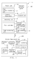
- FIG. 1 is a block diagram of an embodiment of an intelligent entrance guard unlocking system.
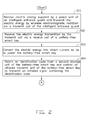
- FIGS. 2 and 3 cooperatively constitute a signal flowchart of an embodiment of an intelligent entrance guard unlocking method.
- references to “an” or “one” embodiment in this disclosure are not necessarily to the same embodiment, and such references mean “at least one.”
- the references “a plurality of” and “a number of” mean “at least two.”
- the drawings are not necessarily to scale and the proportions of certain parts may be exaggerated to better illustrate details and features of the present disclosure.
- Coupled is defined as connected, whether directly or indirectly through intervening components, and is not necessarily limited to physical connections.
- the connection can be such that the objects are permanently connected or releasably connected.
- comprising when utilized, means “including, but not necessarily limited to”; it specifically indicates open-ended inclusion or membership in the so-described combination, group, series and the like.
- FIG. 1 shows an intelligent entrance guard unlocking system 1.
- the intelligent entrance guard unlocking system 1 can include but not limited to an intelligent entrance guard 100 and a battery-free smart key 200.
- the intelligent entrance guard 100 can include a first controller 10, a power unit 11, a current transmitter 12, a transmit coil 13, a first storage unit 14 and an infrared receive unit 15 and an unlocking unit 16.
- the power unit 11 can be a battery.
- the first storage unit 14 can be used to store a predefined identification code.
- the predefined identification code can be an identification code of a smart key matched with the intelligent entrance guard 10.
- the current transmitter 12 of the intelligent entrance guard 100 can transmit electric energy of the power unit 11 by wireless electromagnetic radiation via the transmit coil 13.
- the battery-free smart key 200 can include a current receiver 21, a receive coil 22, a current convertor 23, a second controller 24, a second storage unit 25 and an infrared transmit unit 26.
- the second storage unit 25 can be used to store an identification code of the battery-free smart key 200.
- the current receiver 21 can receive the electric energy if it is within a predefined distance of the transmit coil 13 via the receive coil 22 and power the battery-free smart key 200 via the received electric energy.
- the battery-free smart key 200 is started to work when being powered. That is, the second controller 24 can obtain the identification code from the second storage unit 25. The second controller 24 can further control the infrared transmit unit 26 to transmit an infrared signal containing the identification code.
- the infrared receive unit 15 of the intelligent entrance guard 100 can receive the infrared signal.
- the intelligent entrance guard 100 can obtain the identification code from the infrared signal.
- the intelligent entrance guard 100 can compare the identification code obtained from the infrared signal to the predefined identification code stored in the storage unit 14. If the identification code matches with the predefined identification code, the unlocking unit 16 can control to unlock the intelligent entrance guard 100.
- the details are as follows.
- the current transmitter 12 can electrically couple the power unit 11 with the transmit coil 13.
- the current transmitter 12 can be a current transmission circuit, and used to optimize the electric energy received from the power unit 11.
- the current transmitter 12 can receive electric energy supplied by the power unit 11, and filter noises of the received electric energy, and further transmit the filtered electric energy in a way of wireless electromagnetic radiation via the transmit coil 13.
- the electric energy can be alternating current.
- the current receiver 21 can electrically couple with the receive coil 22.
- the current receiver 21 can be used to receive the electric energy from the transmit coil 13 via the receive coil 22.
- the current receiver 21 can be a current receiving circuit, and the current receiver 21 can be used to filter noises of the electric energy received from the receive coil 22.
- the electric energy can be alternating current.
- the receive coil 22 can be coupled with the transmit coil 13.
- the transmit coil 13 can make the receive coil 22 generate induced current in a form of electro-magnetic induction, and the induced current can be alternating current.
- the current convertor 23 can electrically couple the current receiver 21 with the second controller 24 and the second storage unit 26.
- the current convertor 23 can be used to convert the alternating current into direct current and power the battery-free smart key 200 via the current, as if the battery-free smart key 200 can be powered by a battery of itself.
- the second controller 24 can electrically couple the second storage unit 25 with the infrared transmit unit 26.
- the second controller 24 can be used to obtain the identification code from the second storage unit 25 after the battery-free smart key 200 has been powered.
- the second controller 24 can further control the infrared transmit unit 26 to transmit the infrared signal containing the identification code.
- the first controller 10 can electrically couple the infrared receive unit 15 with the first storage unit 14 respectively.
- the first controller 10 can be used to receive the infrared signal via the infrared receive unit 15.
- the first controller 10 can obtain the identification code from the infrared signal.
- the first controller 10 can compare the predefined identification code obtained from the first storage unit 14 with the identification code.
- the unlocking unit 16 can electrically couple with the first controller 10.
- the unlocking unit 16 can control to unlock the intelligent entrance guard 100 when the identification code is matched with the predefined identification code.
- the unlocking unit 16 cannot control to unlock the intelligent entrance guard 100 when the identification code is not matched with the predefined identification code.
- the intelligent entrance guard 100 can further include a first current-stabilizing unit 17.
- the first current-stabilizing unit 17 can electrically couple the power unit 11 with the current transmitter 12.
- the first current-stabilizing unit 17 can be used to stabilize the current of the power unit 11 to prevent the current to exceed a predefined value suddenly, which may damage the electronic components of the intelligent entrance guard 100.
- the intelligent entrance guard 100 can further include a light controlling unit 18 and a light emitting unit 19.
- the light controlling unit 18 can electrically couple the first controller 10 with the light emitting unit 19.
- the light controlling unit 18 can be used to control the light emitting unit 19 to emit light with one color to prompt the user that the verification is successful when the identification code is matched with the predefined identification code.
- the light controlling unit 18 can further control the light emitting unit 19 to emit light with another color to prompt the user that the verification is unsuccessful when the identification code is not matched with the predefined identification code.
- the battery-free smart key 200 can further include a second current-stabilizing unit 27.
- the second current-stabilizing unit 27 can couple the current receiver 21 with the current convertor 23.
- the second current-stabilizing unit 27 can be used to stabilize the current of the received alternating current to prevent the current to exceed a predefined value suddenly, which may damage the electronic components of the battery-free smart key 200.
- the current convertor 23 can be thus omitted.
- the identification code matched with the predefined identification code can be that the identification code is equal to the predefined identification code and/or the identification code is uniquely corresponding to the predefined identification code.
- the intelligent entrance guard unlocking system 1 can be used but not limited to a vehicle door, a door, a box, a cabinet, an electronic device or other suitable device or object, for safety.
- FIGS. 2 and 3 cooperatively constitute a signal flowchart of an intelligent entrance guard unlocking method.
- the intelligent entrance guard unlocking method is provided by way of example, as there are a variety of ways to carry out the method.
- the control method described below can be carried out using the configurations illustrated in FIG. 1 , for example, and various elements of these figures are referenced in explaining the example method.
- Each block shown in FIGS. 2 and 3 represents one or more processes, methods, or subroutines carried out in the example method.
- the illustrated order of blocks is by example only and the order of the blocks can be changed. Additional blocks may be added or fewer blocks may be utilized, without departing from this disclosure.
- the example method can begin at block 201.
- a current transmitter receives electric energy supplied by a power unit of an intelligent entrance guard, and transmits the electric energy by wireless electromagnetic radiation via a transmit coil of the intelligent entrance guard, and the electric energy is alternating current.
- a current receiver receives the electric energy transmitted by the transmit coil via a receive coil of a battery-free smart key, and the electric energy is alternating current.
- a current convertor converts the alternating current into direct current and power the battery-free smart key via the received electric energy as if the battery-free smart key is powered by a battery of itself.
- a second controller obtains an identification code from a second storage unit of the battery-free smart key after the battery-free smart key has been powered, and further controls an infrared transmit unit of the battery-free smart key to transmit an infrared signal containing the identification code.
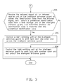
- a first controller receives the infrared signal via an infrared receive unit of the intelligent entrance guard, and obtains the identification code from the infrared signal, and compares a predefined identification code obtained from a first storage unit of the intelligent entrance guard with the identification code, and determines whether the identification code is matched with the predefined identification code, if yes, the process goes to block 206, otherwise, the process goes to block 207.
- a light controlling unit controls a light emitting unit of the intelligent entrance guard to emit light with one color to prompt the user that the verification is successful and an unlocking unit unlocks the intelligent entrance guard.
- the light controlling unit controls the light emitting unit of the intelligent entrance guard to emit light with another color to prompt the user that the verification is unsuccessful and the unlocking unit cannot unlock the intelligent entrance guard.
Landscapes
- Physics & Mathematics (AREA)
- General Physics & Mathematics (AREA)
- Engineering & Computer Science (AREA)
- Computer Networks & Wireless Communication (AREA)
- Electromagnetism (AREA)
- Signal Processing (AREA)
- Lock And Its Accessories (AREA)
Applications Claiming Priority (1)
| Application Number | Priority Date | Filing Date | Title |
|---|---|---|---|
| TW103146683A TW201623062A (zh) | 2014-12-31 | 2014-12-31 | 免電源智慧鑰匙、車輛解鎖系統和車輛解鎖方法 |
Publications (2)
| Publication Number | Publication Date |
|---|---|
| EP3040950A2 true EP3040950A2 (de) | 2016-07-06 |
| EP3040950A3 EP3040950A3 (de) | 2016-08-03 |
Family
ID=53886896
Family Applications (1)
| Application Number | Title | Priority Date | Filing Date |
|---|---|---|---|
| EP15180528.0A Withdrawn EP3040950A3 (de) | 2014-12-31 | 2015-08-11 | Batterieloser smart key und intelligentes eingangsbewachungsentriegelungssystem und entriegelungsverfahren dafür |
Country Status (3)
| Country | Link |
|---|---|
| US (1) | US20160189539A1 (de) |
| EP (1) | EP3040950A3 (de) |
| TW (1) | TW201623062A (de) |
Families Citing this family (5)
| Publication number | Priority date | Publication date | Assignee | Title |
|---|---|---|---|---|
| JP6651710B2 (ja) * | 2015-05-08 | 2020-02-19 | 三井金属アクト株式会社 | 自動車用ドアロック装置 |
| CN106740692A (zh) * | 2016-12-30 | 2017-05-31 | 上海为彪汽配制造有限公司 | 一种基于车辆的遥控器控制系统 |
| US10804969B1 (en) * | 2019-03-25 | 2020-10-13 | Fu Yiu Law | Built-in voltage doubler in a microcontroller unit of a one-cell battery remote for long-distance infra-red (IR) and low-power bluetooth low energy (BLE) transmission |
| CN112541988B (zh) | 2019-09-05 | 2022-09-23 | 华为技术有限公司 | 一种通过车钥匙存储、传输数据的方法及装置 |
| CN111824172A (zh) * | 2020-06-16 | 2020-10-27 | 杭州恒领科技有限公司 | 利用手持终端蓝牙通讯连接的车辆状态唤醒系统 |
Family Cites Families (10)
| Publication number | Priority date | Publication date | Assignee | Title |
|---|---|---|---|---|
| US5113182B1 (en) * | 1990-01-19 | 1995-11-07 | Prince Corp | Vehicle door locking system detecting that all doors are closed |
| US5803043A (en) * | 1996-05-29 | 1998-09-08 | Bayron; Harry | Data input interface for power and speed controller |
| JP3405095B2 (ja) * | 1996-10-22 | 2003-05-12 | 日産自動車株式会社 | 車両用防盗装置 |
| IT1296295B1 (it) * | 1996-12-03 | 1999-06-25 | Aldo Biancone S R L | Perfezionamenti alle serrature di sicurezza |
| DE19729402C2 (de) * | 1997-07-09 | 2003-07-03 | Siemens Ag | Diebstahlschutzsystem für ein Kraftfahrzeug |
| WO2001064479A2 (en) * | 2000-03-02 | 2001-09-07 | Siemens Automotive Corporation | Passive optical identification system |
| WO2006023177A1 (en) * | 2004-08-19 | 2006-03-02 | Futrell Elaine E | Ignition system |
| US9379780B2 (en) * | 2010-12-16 | 2016-06-28 | Qualcomm Incorporated | Wireless energy transfer and continuous radio station signal coexistence |
| WO2012135861A1 (en) * | 2011-04-01 | 2012-10-04 | Tony Lam | Battery powered passive keyless entry system for premise entry |
| US9325187B2 (en) * | 2012-05-21 | 2016-04-26 | Lg Electronics Inc. | Structure of transmission and reception unit in wireless charging system |
-
2014
- 2014-12-31 TW TW103146683A patent/TW201623062A/zh unknown
-
2015
- 2015-07-06 US US14/791,916 patent/US20160189539A1/en not_active Abandoned
- 2015-08-11 EP EP15180528.0A patent/EP3040950A3/de not_active Withdrawn
Non-Patent Citations (1)
| Title |
|---|
| None |
Also Published As
| Publication number | Publication date |
|---|---|
| EP3040950A3 (de) | 2016-08-03 |
| TW201623062A (zh) | 2016-07-01 |
| US20160189539A1 (en) | 2016-06-30 |
Similar Documents
| Publication | Publication Date | Title |
|---|---|---|
| US9773181B2 (en) | Intelligent entrance guard unlocking system and unlocking method thereof | |
| US9569904B2 (en) | Intelligent entrance guard unlocking system and unlocking method thereof | |
| US9563800B2 (en) | Intelligent entrance guard unlocking system and unlocking method thereof | |
| EP3040950A2 (de) | Batterieloser smart key und intelligentes eingangsbewachungsentriegelungssystem und entriegelungsverfahren dafür | |
| US10049517B2 (en) | Wirelessly charged electronic lock with open/closed status reporting | |
| US20160322847A1 (en) | Wireless Battery Charging Systems And Methods | |
| US8774714B2 (en) | External power supply system for a lock comprising NFC-type contactless communication means | |
| EP2792043B1 (de) | Verfahren und vorrichtung zum laden einer batterie in einem mobilfunkteil mittels nahfeldkommunikations (nfc) antenne | |
| US9547947B2 (en) | Intelligent entrance guard unlocking system and unlocking method thereof | |
| US9876386B2 (en) | Wirelessly powered door lock systems and methods | |
| TWI633028B (zh) | 車輛鑰匙系統及其使用方法 | |
| WO2010143483A1 (ja) | 充電装置 | |
| CN110944883B (zh) | 用于车辆的访问设备 | |
| TW201618983A (zh) | 智慧鑰匙系統 | |
| CN106385112B (zh) | 无线供电的电子门锁 | |
| US9489784B2 (en) | Intelligent entrance guard unlocking system and unlocking method thereof | |
| JP5755356B1 (ja) | キーレスシステム及び携帯機 | |
| US20170149265A1 (en) | Lock wireless charging system | |
| CN104104415A (zh) | 多个蓝牙从设备之间的通讯方法及其应用方法 | |
| CN106274804A (zh) | 车辆钥匙系统及其使用方法 | |
| CN107393099A (zh) | 一种数码锁 | |
| CN111183660B (zh) | 用于操作发射器的系统和方法 | |
| CN105984431A (zh) | 免电源智能钥匙、车辆解锁系统及车辆解锁方法 | |
| CN207302172U (zh) | 一种数码锁 | |
| CN216014089U (zh) | 智能拉杆箱的控制系统及智能拉杆箱 |
Legal Events
| Date | Code | Title | Description |
|---|---|---|---|
| PUAI | Public reference made under article 153(3) epc to a published international application that has entered the european phase |
Free format text: ORIGINAL CODE: 0009012 |
|
| PUAL | Search report despatched |
Free format text: ORIGINAL CODE: 0009013 |
|
| AK | Designated contracting states |
Kind code of ref document: A2 Designated state(s): AL AT BE BG CH CY CZ DE DK EE ES FI FR GB GR HR HU IE IS IT LI LT LU LV MC MK MT NL NO PL PT RO RS SE SI SK SM TR |
|
| AX | Request for extension of the european patent |
Extension state: BA ME |
|
| AK | Designated contracting states |
Kind code of ref document: A3 Designated state(s): AL AT BE BG CH CY CZ DE DK EE ES FI FR GB GR HR HU IE IS IT LI LT LU LV MC MK MT NL NO PL PT RO RS SE SI SK SM TR |
|
| AX | Request for extension of the european patent |
Extension state: BA ME |
|
| RIC1 | Information provided on ipc code assigned before grant |
Ipc: G07C 9/00 20060101AFI20160630BHEP |
|
| STAA | Information on the status of an ep patent application or granted ep patent |
Free format text: STATUS: THE APPLICATION IS DEEMED TO BE WITHDRAWN |
|
| 18D | Application deemed to be withdrawn |
Effective date: 20170204 |