EP3040902A1 - Usb-sicherheitsvorrichtung und verfahren - Google Patents
Usb-sicherheitsvorrichtung und verfahren Download PDFInfo
- Publication number
- EP3040902A1 EP3040902A1 EP16150032.7A EP16150032A EP3040902A1 EP 3040902 A1 EP3040902 A1 EP 3040902A1 EP 16150032 A EP16150032 A EP 16150032A EP 3040902 A1 EP3040902 A1 EP 3040902A1
- Authority
- EP
- European Patent Office
- Prior art keywords
- usb
- locking
- self
- plug
- security
- Prior art date
- Legal status (The legal status is an assumption and is not a legal conclusion. Google has not performed a legal analysis and makes no representation as to the accuracy of the status listed.)
- Granted
Links
Images









Classifications
-
- G—PHYSICS
- G06—COMPUTING OR CALCULATING; COUNTING
- G06F—ELECTRIC DIGITAL DATA PROCESSING
- G06F21/00—Security arrangements for protecting computers, components thereof, programs or data against unauthorised activity
- G06F21/70—Protecting specific internal or peripheral components, in which the protection of a component leads to protection of the entire computer
- G06F21/86—Secure or tamper-resistant housings
-
- G—PHYSICS
- G06—COMPUTING OR CALCULATING; COUNTING
- G06F—ELECTRIC DIGITAL DATA PROCESSING
- G06F21/00—Security arrangements for protecting computers, components thereof, programs or data against unauthorised activity
- G06F21/30—Authentication, i.e. establishing the identity or authorisation of security principals
- G06F21/44—Program or device authentication
-
- G—PHYSICS
- G06—COMPUTING OR CALCULATING; COUNTING
- G06F—ELECTRIC DIGITAL DATA PROCESSING
- G06F21/00—Security arrangements for protecting computers, components thereof, programs or data against unauthorised activity
- G06F21/70—Protecting specific internal or peripheral components, in which the protection of a component leads to protection of the entire computer
- G06F21/82—Protecting input, output or interconnection devices
- G06F21/85—Protecting input, output or interconnection devices interconnection devices, e.g. bus-connected or in-line devices
-
- H—ELECTRICITY
- H01—ELECTRIC ELEMENTS
- H01R—ELECTRICALLY-CONDUCTIVE CONNECTIONS; STRUCTURAL ASSOCIATIONS OF A PLURALITY OF MUTUALLY-INSULATED ELECTRICAL CONNECTING ELEMENTS; COUPLING DEVICES; CURRENT COLLECTORS
- H01R13/00—Details of coupling devices of the kinds covered by groups H01R12/70 or H01R24/00 - H01R33/00
- H01R13/44—Means for preventing access to live contacts
- H01R13/443—Dummy plugs
-
- H—ELECTRICITY
- H01—ELECTRIC ELEMENTS
- H01R—ELECTRICALLY-CONDUCTIVE CONNECTIONS; STRUCTURAL ASSOCIATIONS OF A PLURALITY OF MUTUALLY-INSULATED ELECTRICAL CONNECTING ELEMENTS; COUPLING DEVICES; CURRENT COLLECTORS
- H01R13/00—Details of coupling devices of the kinds covered by groups H01R12/70 or H01R24/00 - H01R33/00
- H01R13/66—Structural association with built-in electrical component
- H01R13/665—Structural association with built-in electrical component with built-in electronic circuit
-
- H—ELECTRICITY
- H01—ELECTRIC ELEMENTS
- H01R—ELECTRICALLY-CONDUCTIVE CONNECTIONS; STRUCTURAL ASSOCIATIONS OF A PLURALITY OF MUTUALLY-INSULATED ELECTRICAL CONNECTING ELEMENTS; COUPLING DEVICES; CURRENT COLLECTORS
- H01R13/00—Details of coupling devices of the kinds covered by groups H01R12/70 or H01R24/00 - H01R33/00
- H01R13/66—Structural association with built-in electrical component
- H01R13/717—Structural association with built-in electrical component with built-in light source
- H01R13/7175—Light emitting diodes (LEDs)
-
- H—ELECTRICITY
- H01—ELECTRIC ELEMENTS
- H01R—ELECTRICALLY-CONDUCTIVE CONNECTIONS; STRUCTURAL ASSOCIATIONS OF A PLURALITY OF MUTUALLY-INSULATED ELECTRICAL CONNECTING ELEMENTS; COUPLING DEVICES; CURRENT COLLECTORS
- H01R2201/00—Connectors or connections adapted for particular applications
- H01R2201/06—Connectors or connections adapted for particular applications for computer periphery
Definitions
- the present invention relates to methods, devices and system for enhancing computer information security by physically blocking unused USB ports with self-locking devices, or by providing USB port self-locking device with internal circuitry that qualifies and secures user peripheral device attached to the computer, and by continuously communicating with a management software application that provides real-time monitoring and warnings when any USB self-locking device is being removed or tampered.
- USB ports provide a serial bus standard for connecting devices to computers.
- Most modem computers include at least one, and usually a plurality of USB ports.
- USB ports are used to connect peripherals such as mice, keyboards, scanners, digital cameras, printers, external storage, etc.
- Serial Bus can plug a portable flash drive or other mass storage device into the port and attempt to download information from the computer. Unauthorized, downloading information from the computer is a security problem. Intentional or unintentional downloading of a malicious code from plugged USB device is another critical security problem.
- US 2008/0041125 A discloses a mechanical lock for USB ports.
- WO 2013042108 A discloses a security plug for preventing access to a USB socket adapted to complete an electrical circuit when inserted into the USB socket such that its removal from the USB socket breaks the circuit and is detected by a host computer.
- This plug requires adaptation of the computer side USB interface. It also deviating from modem USB standards and therefore may not be implemented in USB 2.0 or 3 interfaces.
- USB Port Lock with Blockers A mechanical lock for USB port (“USB Port Lock with Blockers ”) is available from Kensington: Kensington Computer Products Group, A Division of ACCO Brands, 333 Twin Dolphin Drive, Sixth floor, Redwood Shores, CA 94065 ( www.kensington.com ). This method of protection requires the use of one master key (physical key) or a large set of keys for each one of the computers. It also does not offer an effective solution to the protection of USB ports that must be used for keyboard and mouse.
- USB Port Blocker Another mechanical lock for USB port (“USB Port Blocker”) is available from Lindy (LINDY USA, 14327 Bledsoe Rd. Athens, AL 35613 (http://www.lindy-usa.com/). This method suffers from the same disadvantages as the previous mechanical lock.
- Security Software that locks and manages the USB ports is available. However, as with any software based security measure, this software may be bypassed, for example if the computer is infected, or if the abuser has obtained administrator permissions.
- DeviceLock® manufactured by DeviceLock, Inc. of San Ramon, CA 94583, USA provides network administrators the ability to set and enforce contextual policies for how, when, where to, and by whom data can or cannot be moved to or from company laptops or desktop PCs via devices like phones, digital cameras, USB sticks, CD/DVD-R, tablets, printers or MP3 players. Administrators can control which users or groups can access USB and other removable and Plug-and-Play devices. Devices can be set in read-only mode while controlling access to them depending on the time of day and day of the week.
- USB flash dive control software may be downloaded from http://www.softpedia.com/get/System/System-Miscellaneous/USB-Port-Blocker.shtml
- USB blocker software may also be obtained from iSM - Institut für System-Management, Oldendorfer Str. 12, 18147 Rostock, Germany (http://www.usb-blocker.com/).
- US patent application number 937,58/13 entitled “electro-mechanic USB locking device” depicts an electromechanical USB port protection device capable of mechanically block unused USB port, thus preventing the connection of any USB device to that port. Removal of the device requires electrically energizing the lock using security code.
- Security software provides scalable and secure centralized keys management. The device provides clear and continuous user visual indications when device is secure. Device derivative secures USB cable to the computer USB port.
- US patent application number 20130067534 entitled “Computer motherboard having peripheral security functions” discloses a secure motherboard for a computer, wherein each user accessible peripheral port is protected by hardware based peripheral protection circuitry soldered to the motherboard.
- the protection circuitry provides security functions decreasing the vulnerability of the computer to data theft.
- User input ports such as keyboard and mouse peripheral ports are coupled to the computer through a security function that enforce unidirectional data flow only from the user input devices to the computer. This protection method is not easy to implement outside the manufacturing plant.
- USB gateway connected to a plurality of host computers having a USB device port connect to a peripheral device; and a security circuitry.
- the security circuitry comprises: a pre-qualification microcontroller; a mode select switch connected to the peripheral device port and selectively connecting it to one of: the pre-qualification microcontroller; or to a host selector switch that switches among the plurality of connected host computes.
- USB port lockers for example as available from Kensington and Lindy can be removed with the use of a relatively simple mechanical key. As with other mechanical keys, these locks may be defeated. The small size of a USB port may prevent the installation of a sophisticated mechanical lock. Also the use of mechanical keys is inefficient and insecure in large organizations as there is a need for a master key or a need to maintain a large set of keys matching each particular lock in each particular computer (one computer may have up to 10 locks). It also does not provide a secure solution for the authorized use of USB keyboards and mice. In view of the security risks associated with USB devices connected to computers, and in view of the shortcoming of prior art USB protection methods and devices, there is a need for a USB port protection device and method that at least provide:
- Self-locking USB cable permanently attached to a filter device that filter and secure the connected user peripheral device.
- a USB locking device that only allows a connection of USB mouse or keyboard.
- methods, devices and system for enhancing computer information security by physically blocking unused USB ports with self-locking devices, or by providing USB port self-locking device with internal circuitry that qualifies and secures user peripheral device attached to the computer, and by continuously communicating with a management software application that provides real-time monitoring and warnings when any USB self-locking device is being removed or tampered.
- the self-locking devices use a spring loaded teeth in the USB plug that lock into tab spaces in the USB jack. Visual indicator provides positive assurance when all ports are secure.
- Each self-locking devices include a security circuit which is uniquely paired with the protected port. Some self-locking devices include data filters that only enable connecting authorized peripheral devices.
- Some embodiments of the current invention provide a USB port self-locking device with internal circuitry that qualifies and secures the attached user peripheral device.
- Other embodiments of the current invention combine multiple self-locking USB devices installed in multiple computers to continuously communicating with a management software application that provides real-time monitoring and warnings when device is being removed.
- a self-locking USB protection plug device comprising: a rugged body shaped and sized to be inserted into a standard USB jack of a protected computing apparatus, wherein said rugged body is having at least one spring, said at least one spring is having a locking tooth sized and shaped lock inside a shielding tab holes of said standard USB jack; a faceplate attached to said body, said faceplate is larger than said standard USB jack to prevent an attempt to insert a thin tool between the inserted self-locking USB plug body and the USB jack; a printed circuit board assembly, housed within said body, said printed circuit board assembly is having contacts for electronically interfacing with said protected computing apparatus via said standard USB jack; an LED indicator attached to said printed circuit board assembly and visible on said faceplate; and an active authentication chip attached to said printed circuit board assembly, wherein said active authentication chip is capable of communicating with, and authenticating in front of a security software executed by said protected computing apparatus, and wherein said active authentication chip is capable of causing said LED indicator to indicate that said
- the body is made of metal
- said faceplate is made of metal
- said faceplate is welded to said body.
- At least one spring is a leaf spring, wherein said at least one leaf spring is bent to form a corresponding locking tooth.
- the at least one leaf spring is part of said body made of metal.
- the metal body is having two leaf springs, each of said two leaf springs is bent to form a corresponding locking tooth.
- attempting to pull the self-locking USB protection plug device out of said standard USB jack causes said leaf springs to be bent and further lock the USB protection plug to said standard USB jack.
- the active authentication chip is capable of causing said LED indicator to indicate that said USB jack is not securely protected by an authenticated USB protection plug device.
- the active authentication chip is capable of causing said LED indicator to indicate that at least one USB jack in said protected computing apparatus is not securely protected.
- the faceplate secures in place a cover plates for covering at least one USB jack adjacent to said standard USB jack into which the self-locking USB protection plug device was inserted.
- a self-locking Human Interface Device (HID) filter device comprising: at least one permanently attachable self-locking USB plug having at least one locking tooth to permanently connect said at least one permanently attachable self-locking USB plug to a USB jack of a protected computing apparatus; a USB hub having an upstream port coupled to said self-locking USB plug and having at least a first downstream port and a second downstream port; an authentication chip coupled to said first downstream port of said USB hub, to enable positive authentication of the self-locking filter device by software installed at said protected computing apparatus; a USB HID Device Emulator function, for emulating a standard USB keyboard and mouse, coupled to said second downstream port of said USB hub; at least one USB device port, for connecting a user HID device to the HID filter; and at least one USB Host Emulator, for emulating USB host stack, coupled to said USB device port on one side and to said USB HID Device Emulator function on the other side.
- HID Human Interface Device
- At least two of said: authentication chip; said USB hub; and said USB HID Device Emulator function are integrated into a single chip.
- the self-locking HID filter further comprises a physical unidirectional data flow enforcing device connected between said USB HID Device Emulator function and said USB Host Emulator allowing data flow only from said HID user device to said protected computing apparatus.
- the self-locking HID filter further comprises: a housing, for housing: said USB hub, said authentication chip, USB Device Emulator function, said at least one USB Host Emulator, and said at least one USB device port; and a tamper evident sticker, attached to said housing for indicating tampering attempt of said housing.
- At least one permanently attachable self-locking USB plug is integrated into said housing.
- the self-locking HID filter further comprises a second permanently attachable self-locking USB plug, wherein said second permanently attachable self-locking USB plug is integrated into said housing.
- the self-locking HID filter further comprises a cable connecting said housing to said at least one permanently attachable self-locking USB plug.
- a self-locking peripheral filter device comprising: a permanently attachable self-locking USB plug having at least one locking tooth to connect to a USB jack of a protected computing device; a USB hub having a upstream port coupled to said self-locking USB plug and having al least a first downstream port and a second downstream port; an authentication chip coupled to said first downstream port of said the USB hub to enable positive authentication of the self-locking peripheral filter device by software installed at said protected computing device; at least one USB device port for connecting a user device; a Qualification Microcontroller having host USB port for USB enumeration and qualification of a user device coupled to said at least one USB device port; and a USB mode select switch, controlled by the Qualification Microcontroller, coupled to USB device port, wherein said USB mode select switch couples said USB device port to said USB device port of said Qualification Microcontroller before said user device is qualified, and couples said USB device port to said and a second downstream port of said USB hub when said user device was qualified.
- the self-locking peripheral filter further comprises at least a first LED indicator for indicating at least one of: qualification status of said user device, and authentication status of said authentication chip.
- At least two of: said USB hub; said authentication chip; said Qualification Microcontroller; and said USB mode select switch are integrated into a single electronic chip.
- the self-locking peripheral filter further comprises: a housing for housing: said USB hub; said authentication chip; said at least one USB device port; said a Qualification Microcontroller; and said a USB mode select switch; and a tamper evident sticker, attached to said housing for indicating tampering attempt of said housing.
- It is another aspect of the current invention to provide a method of protecting USB jacks of a computing device comprising: obtaining identification of at least one USB protection device; entering said identification of said at least one USB protection device into the organization database; installing a security application in a protected computing device having a housing and at least one USB jack exposed on said housing; loading security key associated with said identification of said at least one USB protection device from said organization database to said security application in a protected computing device; inserting and permanently locking said at least one USB protection device into said at least one exposed USB jack; and qualifying said at least one USB protection device by said security application.
- the method of protecting USB jacks of a computing device further comprises: connecting said protected computing device to a centralized management system server executing a centralized security application; and logging security events detected by said at least one USB protection device on said centralized management system server.
- the method of protecting USB jacks of a computing device of further comprises: detecting a security event by at least one of: at least one of said protection devices; and said security application; disabling all said exposed USB jacks; disabling operation of all said protection devices; and providing visual indication on said protection devices.
- an internal USB protection plug device comprising: a printed circuit board assembly; a receptacle connector, soldered to said printed circuit board assembly for electronically interfacing with an internal USB port internal to a housing of a protected computer; an active authentication chip attached to said printed circuit board assembly, wherein said active authentication chip is capable of communicating with, and authenticating in front of a security software executed by said protected computing apparatus, and wherein security software is capable of generating a security event if at least one internal USB port internal to a housing of a protected computer is not protected by an authenticated internal USB protection plug device.
- the internal USB protection plug device further comprises an LED indicator attached to said printed circuit board assembly, Wherein said active authentication chip is capable of causing said LED indicator to indicate that said USB jack is securely protected by an authenticated USB protection plug device.
- the functional blocks are not necessarily indicative of the division between hardware circuitry.
- one or more of the functional blocks e.g., processors or memories
- the programs may be stand alone programs, may be incorporated as subroutines in an operating system, may be functions in an installed software package, and the like.
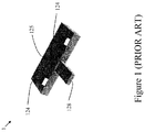
- FIG. 1 illustrates a prior-art USB security plug for preventing access to the USB port based on PCT application WO 2013/042108 A1 .
- This prior-art security plug device 1 is used to prevent access to USB port.
- the security plug 1 has a planar body portion dimensioned for insertion into the frame of the USB jack (not shown in this figure).
- the body portion may also be dimensioned such that an end surface thereof is flush with an outer edge of the USB jack frame when the plug is fully inserted therein.
- At least one prong 124 is supported by a major surface 125 of the body portion for engaging a corresponding aperture in the USB jack frame whereby an edge of the aperture engages the prong 124 and impedes removal of the plug from the socket.
- a frangible tab 128 fixed to the end surface of the plug and adapted for easy removal therefrom after insertion of the plug into the USB jack.
- the frangible tab 128 is adapted to be fractured from the body portion upon attempting to remove the plug from the socket leaving a facture mark. This both prevents removal while also providing an immediate visual indication that the plug has been tampered with.
- Also described in this patent application are security functions that enable software detection of the plug presence through software running on the host computer.
- a resistor R (not shown in this figure) of sufficiently high value e.g. 100 KOhm to impose little current drain.
- Software in the host computer monitors the current flowing between VBUS and Ground so as to detect whether the security plug is connected or removed as a function of current flow. Specifically, any status in the connection or disconnection of the security plug while the computer is operating can be detected in this manner.
- a memory device storing a unique ID may be connected across the data pins 2 and 3 so as to allow the host computer to identify the device.
- the host computer monitors the USB ports and detects when a device is removed or inserted and uses the ID to establish the ID of the device. The user is then prompted to enter an authorization code that is matched to a database of authorized users stored in the computer in order to determine whether the user is authorized to remove or insert the identified device and take precautionary or evasive action if necessary.
- Figure 2 illustrates a cross-sectional view of another prior-art mechanical USB locking plug device described in US Patent application US 2008/0041125 A1 .
- Locking member 208 is pivotally connected to the rear end of retaining sheath. Locking member 208 is provided with two protrusions 218, which correspond to standard openings in a USB port. Locking member 208 has a bent, preformed shape, such that in the absence of external forces it runs diagonally; its front end is farther inward than its back end. Lock 10 further includes lock button 206 which protrudes from the rear end of housing 214. Lock button 206 is depressible by a user to lock the lock 10. Lock button 206 is connected to linear cam 204, which pivots locking member 208 by cooperating with the ramped camming surface of locking member 208.
- Figure 3 schematically illustrates a high-level block-diagram of a self-locking USB security plug having an electronic authentication chip according to an exemplary method and embodiment of the present invention showing the self-locking USB security plug before it was plugged into the protected computer USB jack.
- the USB security plug 20 having an enclosure 5 has a USB plug 13 designed to fit standard USB jack 31 of host device 30 (only part of which is seen in this figure) such as the one illustrated to at the left side.
- USB jack 33 may be any open and unused USB port in host PC, laptop, docking station, appliance, server etc. (item 30).
- USB jack 31 may be USB 2.0, USB 3.x, Micro USB etc.
- Electrical contacts 12 of USB security plug 20 are arranged to touch the electrical contacts 33 of USB jack 31.
- Authentication chip 27 is connected to the USB plug contacts 12 through lines 9a and 9b to enable software loaded on protected computer 30 to positively authenticate the USB security plug 20. Power required for the Authentication chip 27 and other circuitry is received from host computer USB contacts 33 via plug contacts 12 and line 10. Power is 5 VDC (5 Volts Direct Current) as defined in the applicable USB standard. Authentication chip 27 also drives LED 19 visible on the exposes surface of enclosure 5 to provide user indications of device status. Preferably LED 19 is bi-color LED to provide blinking green illumination when port is secured and steady or blinking red illumination when port in not secured.
- LED 19 may serve one or few of the following several purposes:
- chip 27 provides strong authentication by authentication process against the security software installed in the protected host (as will be detailed for example in figures 12 , 15 and 16 ).
- the authentication process also protects against removal of the USB plug and inserting another (even a genuine) plug. Since each plug has unique authentication properties, any other plug purchased from the same manufacturer, or made by someone else would not correctly authenticate unless it was issued by the security organization (The configuration, authentication an issuing of the USB plugs is similar to the process of issuing smart-cards or tokens to users. An exemplary process is seen in figures 12 , 15 and 16 ).
- a security software installed on the host periodically monitors the presence and authenticity of all the plugs that were installed in the host. If one or more of the plugs is missing or fail to authenticate, the security software installed on the host may take on of few corrective actions such as:
- the installed plug monitors the existence and integrity of the security software installed on the host by periodically attempting authentication. If the software installed on the host fails to authenticate the plug, the plug may take one or more corrective actions such as:
- a centralized management system for example executed on Centralized Security Management Server 199 seen in figure 7 , enables the following operation by authorized personnel:
- Spring 16 connected to self-locking teeth 8 enables one-time locking of the USB security plug 5 inside the protected computer 30 USB jack 31.
- One or more teeth 8 are shaped to enable one-time insertion by force into the one or more grounding tab spaces 34 in the mating jack 31.
- Spring 16 may be a torsion spring, leaf spring or any other type of elastic component.
- the locking mechanism comprises of two teeth formed as part of the metal body of the enclosure 5 of the USB security plug 20. Note that in the preferred embodiment of the current invention the whole electronic circuitry is contained inside the USB contacts plate 21 as will be shown in figure 5 .
- Enclosure 5 is designed to withstand mechanical tampering and therefore it is preferably made from material such as strong stainless steel or Phosphor Bronze formed metal sheet.
- One or more cover plates 14 are designed to fill the gap between the security plug enclosure 5 and the mating USB connector 31. These cover plates 14 may be used to cover one or more nearby USB or other computer ports. Cover plates 14 may be formed in different shapes to allow flexible deployment options in different computers having different arrangement of USB ports.
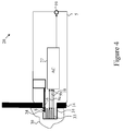
- Figure 4 schematically illustrates a high-level functional diagram of the same self-locking USB security plug 20 according to the exemplary embodiment of the current invention illustrated in figure 3 above wherein in this figure the self-locking USB security plug device is inserted into the host's USB jack 31.
- USB plug contacts 12 of self-locking USB security plug 20 are touching host USB connector 31 mating contacts 33 to connect the authentication chip 27 USB interface to the connected computer USB bus to start device authentication (assuming that the computer is powered on).
- the coupled Authentication and security function 27 is powered and recognizes initial insertion state it shall provide positive user indications through LED 19 that illuminate in green color. Authentication failure may be indicated through LED 19 illumination in red color.
- An authentication state of "failure" is caused if the security plug does not recognized by security software as belonging to the organization or was not paired to the specific computer or port where it was inserted.
- a security event may trigger one or more of the corrective actions stated above.
- a security events may optionally be detected, logged and acted by the plug. For example, If the security software was removed or disabled in the host and the plug is powered for a preset duration without authentication, the event may optionally be logged in the plug as a security event. This security event may permanently put the plug in a "failure" state. Alternatively, the event may be logged and reported to the security software once it has been restored.
- Figure 5 depicts a mechanical diagram of the self-locking USB security plug of the current invention illustrated in figures 3 and 4 above.
- the self-locking USB security plug metal body enclosure 5 is made of thin formed metal sheet material (for example stainless steel or Phosphor Bronze) to provide mechanical strength and tampering protection.
- the self-locking USB plug 20 is shaped to enter the mating USB jack and is equipped with the two locking tooth 8a and 8b designed and shaped to enter the mating USB jack 31 grounding tab holes 34 (as shown in figures 3 above).
- springs 16a and 16b are integral part of the body 5 of self-locking USB plug 20 and force locking tooth 8a and 8b respectively into the corresponding grounding tab holes 34 in USB jack 31.
- the front edges of locking tooth 8x are slanted such that they flex springs 16x towards PCB 21 as self-locking USB plug 20 is inserted into USB jack 31.
- springs 16x return to their original shape forcing force locking tooth 8a and 8b respectively into the corresponding grounding tab holes 34 in USB jack 31.
- locking tooth 8x are slanted such that if self-locking USB plug 20 is pulled in an attempt to pull it out of USB jack, locking teeth 8x further penetrate into the grounding tab holes 34 in USB jack 31. This causes springs 16x to be bent upwards and the whole connector is bent upwards as well. This increases the locking effect and the mechanical strength in which self-locking USB plug 20 is locked in USB jack 31. As a result, attempt to remove USB plug 20 is locked from USB jack 31 is likely to cause destruction of USB plug 20, USB jack 31 or both.
- locking tooth 8x (in here “x” may stand for the letters “a”, “b”, etc.) are constructed as part of spring surfaces 16x to provide proper flexible force against the mating USB connector 31 and to support positive locking.
- USB jack shielding tab holes 34 are mechanically secure the USB security plug device into position inside host USB jack 31.
- Small PCBA (Printed Circuit Board Assembly) 21 is having gold contacts 12 printed on it on the top side.
- Authentication chip 27 (not shown in this figure) is soldered or bonded to the bottom side of this PCBA 21 together with all other required electronic components such as LED 19.
- Metal faceplate 22 is preferably welded to the metal body 5 of the self-locking USB plug 20 to provide proper mechanical strength and therefore to resist potential tampering.
- Ultrasonic welding may be used to weld faceplate 22 to the metal body 5 of the self-locking USB plug 20.
- other strong materials may be used.
- faceplate 22 is at least slightly larger than the size of USB jack 31.
- this metal faceplate 22 is used:
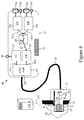
- Figure 6 schematically illustrates a high-level block-diagram of self-locking USB HID (Human Interface Device) security filter having a unidirectional data diode function 40 according to another exemplary embodiment of the present invention.
- USB HID Human Interface Device
- This embodiment of the current invention is complementing the self-locking USB plug embodiment shown in figures 3 to 5 above by enabling secure connection of standard USB keyboard and USB mouse to the protected computer.
- the self-locking USB HID security filter having a unidirectional data diode function 40 in this embodiment of the current invention comprises an enclosure 37.
- Enclosure 37 is having a permanently attached USB cable 28 coupled to a self-locking USB plug 35.
- USB cable 28 is a shielded cable having a shield for example a metal shield or braded steel shield to protect the inner electric conductors within the cable against attempts to connect a USB device directly to them.
- Cable 28 is terminated with a self-locking plug 35 which is over-molded by plastic jacket 15 to permanently attach USB cable 28 to the self-locking plug 35 and to the protected computer 30.
- Self-locking USB plug 35 is mating with the protected computer 30 USB jack USB jack 31 and is similar in its construction to the self-locking USB plug 13 of device 20 shown in figures 3 to 5 above.
- Self-locking USB plug 35 electrical contacts are coupled through lines 9x to the permanently attached USB cable 28.
- USB cable 28 is permanently attached to the device enclosure 37.
- USB signals from USB cable 28 are coupled to the USB hub function 29 upstream port 66.
- USB hub function 29 may be standard two-port USB 1.1 or USB 2.0 hub or other USB hub.
- the USB hub function 29 downstream USB ports 47a and 47b are coupled to the Authentication Chip (AC) 32 and to the Device Emulator function (DE) 36 respectively.
- AC 32 bay be using a standard anti-counterfeiting chip such as InsideSecure VAULTIC405 that provides the following Cryptographic Services:
- AC 32 may support the following Cryptographic Algorithms:
- AC 32 may support the following:
- USB user keyboard and mouse USB jacks 24a and 24b are coupled to Host Emulator functions (HE) 25a and 25b respectively.
- Host emulator functions 25x emulates a standard PC USB HID host stack by receiving user keyboard and mouse entries (keyboard and mouse are not seen in this figure) and converting them into a proprietary unidirectional serial data streams 67x respectively.
- Host Emulator functions 25x is preferably a microcontroller, ASIC (Application Specific Integrated Circuit), FPGA (Field Programmable Gate Array), System on a Chip or any other computing function that is capable of performing the required emulation.
- Host emulator functions 25x may be integrated into a single electronic component to reduce the device cost and complexity.
- Unidirectional data enforcing device 26 is preferably and optical isolator, inductive isolator or any other electronic circuitry capable of assuring unidirectional data flow.
- DE Device Emulator function
- Device emulator function 36 emulates a standard PC keyboard and mouse devices by receiving proprietary unidirectional data stream 65 from Host Emulators 25x and generating matching user keyboard and mouse entries over USB port 47b.
- USB downstream port 47b is coupled through the hub function 29 to the protected computer USB port 31.
- Device Emulator function 36 is preferably a microcontroller, ASIC (Application Specific Integrated Circuit), FPGA (Field Programmable Gate Array), System on a Chip or any other computing function that is capable of performing the required emulation.
- ASIC Application Specific Integrated Circuit
- FPGA Field Programmable Gate Array
- System on a Chip any other computing function that is capable of performing the required emulation.
- USB jack 24 connected to one HE 25 is used.
- a plurality of USB jacks 24x are used, each coupled to a corresponding HR 25x (two are seen herein, but more may be used by extending the topology).
- Unidirectional serial data transfer from Hex to USB Hub 29 may be done by one of few options which were not shown in the figure to prevent its cluttering:
- LED 19 is coupled to authentication chip 27 to provide user indications of the device security state.
- LEDs 19a and 19b are coupled to the Host Emulator functions 25a and 25b to provide user indications of the device port status. Such indications may include: red illumination if connected device is being rejected (device is not HID), green if device is accepted, etc.
- Tamper Evident sticker 18 may be fitted on the device enclosure 37 to provide clear user indications in case that the enclosure 37 is being mechanically tampered. Such sticker is preferably holographic surface having a special adhesive layer. Once the label is peeled or removed - clear indications of such removal appears in or under that label. Tamper Evident sticker 18 may change color or expose text such as "Void" if peeled from the enclosure 37 surface.
- USB hub 29, Authentication chip 32 and Device Emulator functions may be integrated inside one microcontroller chip to reduce the device complexity and cost. Hub may be eliminated if integrated device may support a composite device having authentication function together with USB HID device. Further cost reduction is possible if one or more Host Emulator 25x function may be also integrated into the same chip.
- the self-locking USB HID security filter having a unidirectional data diode function 40 is coupled to a software application running on the protected computer 30 that performs continues USB port monitoring and authentication to assure that all USB ports are properly protected by self-locking USB security plugs 15, cover plates 14 and HID filters 40.
- Protected computer 30 may be coupled to one or more Centralized Security Management Servers (CSMS) 199 through Local Area Network (LAN) or Wide Area Network (WAN) 197.
- CSMS may comprise of local or remote data base 190 that stores the system events log and the protected computers configuration. It can also send warnings or alerts to the security administrator in case that security event such as USB plug device removal was detected. Warnings may be sent through SMS (192), email (191) or other communication methods.
- AC 32 may cut communication with USB jacks 24x when a security event was detected, for example failure to authenticate in front of a security software installed in the host 30, or detection of an unauthorized device connected to USB jacks 24x.
- Communication with USB jacks 24x may be cut by disabling one or few of: DE 36, unidirectional data enforcing device 26, or HEs 25x.
- the security device 40 may be used to filter USB devices other than HID through pre-programmed profile or through field programming of the allowed device profiles. Programming may be performed using a USB Type-A to USB Type-A cable connecting USB port 24x to a mobile phone, a laptop, a proprietary programming device or a computer. The optional re-programming changes the filtering operation defined below.
- USB HID security filter 40 Since re-programming is a security risk, in some embodiments all electronics in USB HID security filter 40 is hardware, non programmable.
- USB HID security filter 40 is programmable only during manufacturing
- USB HID security filter 40 is programmable only by authorized users through a connected computer (not seen in the figures) having special software application. It may be preferred to use a separate (administrative) computer having special software application for this purpose and not install the special software application on the user computer 30 as user computer 30 preferably should not be able to modify the operation of its USB plugs.
- the computer having special software application may be a mobile or laptop computer and interface with the USB UID security filter via USB plug 24.
- the HE 25a is a microcontroller having a flash memory for storing the reprogrammable filtering characteristics.
- the microcontroller supports encrypted memory functions to secure these filtering characteristics.
- USB HID security filter 40 is based on at least one of:
- Figure 7 illustrates a high-level functional diagram of a self-locking USB HID filter of the current invention similar to the device illustrated in figures 6 above wherein the exemplary embodiment depicted in this figure the device 140 does not have a unidirectional data enforcing device 26 (as shown in figure 6 above).
- the removal of the unidirectional data enforcing device 26 reduces the device cost and also enables return communication from protected computer to the keyboard or mouse. This enables functions such as Caps Lock, Num Lock and Scroll Lock LEDs in keyboards to operate normally.
- DE 36 and or HE 25x may use filtering process to reduce the risk by blocking unauthorized data transfer.
- FIG. 8A illustrates a high-level functional diagram of another USB security filter 180 having a Qualification Microcontroller function 46 according to another exemplary embodiment of the current invention.
- Qualification Microcontroller 46 is having a USB host port 56 coupled to a USB mode select switch 39 that switch the USB signals from the device USB port 24.
- the mode select switch 39 controlled by the Qualification Microcontroller 46 via line 57 is switched to pass USB signals to the Qualification Microcontroller 46 host USB port 56.
- Qualification Microcontroller 46 is then enumerating the connected device and compares the received enumeration parameters with the permitted parameters pre-programmed on it.
- Such pre-programmed parameters may include one or more of the following USB characteristics: USB device class, USB device sub-class, protocol, manufacturer ID, Device name, and device serial number, hub and composite device end-point characteristics etc.
- the Qualification Microcontroller 46 command the mode select switch 39 to switch to the other position - passing USB signals to USB line 55 that is coupled to the USB hub 29 second downstream port 89.
- USB hub 29 is coupled to the protected computer 30 USB port 31 through permanently connected USB cable 28 and self-locking USB plug 35.
- Allowed USB device profile may be loaded by the user when device 180 is already attached to the protected computer through a USB Type-A to USB Type-A cable connected to device port 24.
- LED 99 is coupled to the Qualification Microcontroller 46 to provide user indications of the connected device qualification state. Green illumination may indicate that device is qualified (accepted) while red may indicate that device was rejected (not permitted).
- one device USB jack 24a is used in connection with one mode select switch 39, one QM 46 and one LED 99. It should be noted that the device may be extended to use two (or more) device USB jacks by duplicating the required elements.
- the device includes means to detect and protect against replacing an authorized USB device connected to USB plug 24a with a different, potentially hostile device.
- USB Hub 29 may have internal registers that can be polled by QM 46 through line 58 (which may use be I2C protocol for example) to find the real time status of each downstream port.
- Current sensor 59 may be added on the device power lines in order to detect the exact current consumed by the device. This will further enhance the security of this apparatus by sensing abnormal power consumption conditions. For example if USB mouse is having an internal cellular modem - this may be sensed by high peaks in the current. QM may have an A/D input that will sample these currents after current sense amplifier 61 and compare them with normal behavior characteristics programmed into it. Current sense 59 may be shunt resistor or an integrated current sensor with amplifier 59.
- FIG. 8B schematically illustrates a high-level functional diagram of another USB security filter according to another exemplary embodiment of the present invention.
- USB mode select switch 39 disconnects USB plug 24x from the rest of the electronics. Once the user device is authenticated by QM 46, USB mode select switch 39 connects USB plug 24x to the rest of the electronics (in this example to USB Hub 29. However, this embodiment may be combined with other embodiments disclosed herein and USB mode select switch 39 connects USB plug 24x to a corresponding HE 25x, or may connect an HE 25x with unidirectional device 26, or may connect a unidirectional device 26 with a DE 36, etc.
- QM 46 continue to monitor data exchange with USB jack 24x and if suspicious activity is detected QM 46 commands USB mode select switch 39 to revert to the secure (disconnected) state.
- QM 46 may report a security event to AC 32 via an optional reporting line 857.
- QM 46 may attempt to re-enumerate the user UBB device connected USB jack 24x before reporting a security event to AC 32.
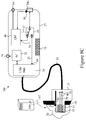
- FIG. 8C schematically illustrates a high-level functional diagram of another USB security filter according to yet another exemplary embodiment of the present invention.
- a physical disconnection detector 98 for example a micro switch, is installed at USB jack 24x to detect user USB device disconnect and cause QM 46 to repeat the enumeration process.
- Figure 9A schematically depicts a mechanical diagram of the same self-locking USB security filter such as embodiments 40, 140 and 180 of the current invention illustrated in figures 6 to 8 above.
- Self-locking plug 35 is over-molded by plastic jacket 15 to permanently attach USB cable 28 to the protected computer 30 USB port 31 (not shown in this figure).
- USB Cable 28 is permanently connected to the enclosure 37 that hosts the device electronic components PCBA.
- enclosure 37 is made of plastic.
- enclosure 37 is made of metal and is welded, for example ultrasonically to deter tampering. Tampering Evident sticker 18 is placed on the enclosure 37 parting-link to assure that the sticker will be damaged if an attempt is made to open the enclosure 37 in order to tamper with the device PCBA.
- device USB jacks 24a and 24b are stacked USB connectors. LEDs 19a and 19b are placed near their respective USB jacks 24a and 24b to provide clear user indications of the connected device state.
- a single device USB jack 24a may be used as seen in figure 8 .
- LED 19 provides user indications for the device security state for example through short light-pipe positioned underneath the plastic enclosure 37 surface.
- cable 28 is a reinforced cable having steel braid to deter physical access to electrical conductors within it.
- Figure 9B schematically illustrates mechanical diagrams of self-locking security plugs according to other exemplary embodiments of the present invention.
- FIG. 9B (1) to 9B(5) respectively use a single housing 410a, 410b, 410c, 410d and 410erespectively instead of two parts (15 and 37 as in figures 6 , 7 , 8A , 8B , 8C and 9A ).
- cable 28 is missing or internal to the housing 410x
- self-locking plug 35x for example springs ad tooth
- LEDs 19 and optional 19x are seen and marked only in figure 9B (1).
- the self-locking plug 35 (or of self-locking plugs 35a and 35b) are at substantially 90 degrees to USB jack 24 or jacks 24a and 24b.
- self-locking plug 35 (or of self-locking plugs 35a and 35b) are at substantially in line with USB jack 24 or jacks 24a and 24b.
- USB plugs 35a and 36b are used.
- two USB plugs 35a are used, they are spaced such that their distance is equal to the distance in a standard dual USB jack (such as seen in embodiments 400a to 400d, and in figures 9A and 11 ).
- Self locking tooth or teeth may be used on one, and optionally on both USB plugs 35a and 36b.
- electrical contacts may be used in on one, and optionally on both USB plugs 35a and 36b.
- data connection may be used only in one of on one of the USB plugs 35x, while power connection (used for example for disconnect detection) may be used on both USB plugs 35x.
- each USB plug and jack may be performed independently, for example as seen in figures 8A , 8B and 8C .
- Figure 10 illustrates a mechanical diagram of the self-locking security plug 35 shown in figures 6 to 9 above in greater details.
- USB cable 28 is over-molded by the plastic jacket 15 having USB logo embossed on it.
- the self-locking plug 35 is made of stainless-steel, Beryllium Copper or any other suitable metal sheet formed into USB plug shape, having USB contacts 12 placed on insulator 91.
- Metal part 95 also formed to include two leaf springs 16a and 16b that are bent to form tooth 8a and 8b respectively.
- the plug 35 Once the plug 35 is inserted inside the protected computer 30 USB jack 31, it locks inside that jack permanently through the two tooth 8a and 8b that prevent removal by force.
- Figure 11 illustrates an unprotected computer 30 rear panel 44, having 6 exposed USB jacks 31 a to 31 f as used in the prior art.
- exposed USB jacks 31a to 31f are seen on rear panel 44 of housing 944 of unprotected computer 30.
- exposed USB jacks may be located on other parts of the housing 944, for example on the (not seen here) front panel, or top panel.
- Unexposed USB ports may be present on the computer boards, for example the motherboard (not seen here) located within housing 944 of unprotected computer 30.
- USB jacks may be used to plug various USB devices and therefore regarded as security vulnerability. While other ports seen in this figure are exposed and vulnerable, they may be protected using other means not disclose herein.
- Figure 12 schematically illustrates a simplified flow-chart diagram of the preparations phase before protecting the unprotected computer 30 shown in figure 11 above.
- Initialization is required in order to prevent usage of devices purchased by attacker from being deployed or being used as substitute of authentic authorized devices.
- New device initialization may be performed through means such as:
- step 3 new unprotected computer 30 is detected 902 by the CMS through the LAN (Local Area Network) or WAN (Wide Area Network) if located remotely.
- LAN Local Area Network
- WAN Wide Area Network
- step 4 upon detection of a new computer, the CMS load and install 903 the security application 920 into computer 30.
- Security application 920 is preferably be installed at the lowest possible level to assure that it would not be circumvented by other operating system services or applications.
- BIOS / UEFI level application is referable over operating system installed application.
- USB ports identified may be divided automatically or manually into different categories based on parameters such as:
- USB ports are typically not considered as a security threat and therefore may remain unprotected.
- internal unused USB ports may be also protected through using a self locking protection device of the current invention that is adapted to interface mechanically and electronically with the internal USB connector.
- Detected USB port information is loaded into the protected computer database 921 and into the CMS database 905.
- step 6 the user may assign specific roles for each port. For example: one port will be used for HID filter protection device, another for USB printer that is protected through a programmable filter device. All other external USB ports shall be assigned to USB self-locking protection plug devices or covered with the cover plates.
- the CMS may open a support ticket to notify the appropriate field technician that the unprotected computer 30 is ready for protection device installation. This information may be sent to the technician by the CMS through an email, SMS or any other messaging method.
- FIG 13 illustrates a simplified flow-chart diagram of the USB protection devices installation phase on the unprotected computer 30 shown in figures 11 and 12 above.
- USB protection software will prompt the technician which ports should be protected or covered during the installation phase.
- the technician is instructed to place each one of the USB protection devices (963a to 963n respectively) at the appropriate computer 30 USB ports. This is done through textual or graphical instructions (for example a drawing or a short video clip). The technician may be instructed to use protective devices such as:
- Each one of the inserted USB protection devices is being authenticated (961a to 961n respectively) against the unique key entered into the databases 921 and 905 during the preparations phase ( figure 12 step 2).
- the protection device Once the protection device is properly authenticated and approved, its LED will start blinking in green color.
- the technician may then connect to the protected computer 30' the required USB peripheral devices via the self-locking USB protection filters (for example USB keyboard, USB mouse and USB printer as can be seen in the next figure).
- the self-locking USB protection filters for example USB keyboard, USB mouse and USB printer as can be seen in the next figure.
- USB peripheral devices may be recorded (logged) as a security event by the USB protection software 920 on local database 921 and by the CMS server 970 on database 905.
- Such information may include:
- This information may be used by the CMS to generate alarms and warning.
- the CMS may be programmed to send a real-time alert when an attempt is made to connect to protected computer self-locking USB filter a mass-storage class device.
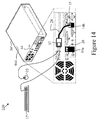
- Figure 14 schematically illustrates a system 220 using the same computer 30' of the pervious figure 11 with self-locking USB protection devices of the current invention installed to protect it.
- USB port 31a is having a self-locking USB plug 20 (seen in figures 3 to 5 ) of the current invention to prevent connection of any USB device.
- USB ports 31b to 31d are covered by cover plate 14a that is secured in place by the self-locking USB plug 20.
- USB jack 31e is having a self-locking HID filter device such as device 40, 140 or 180, connected to it through USB plug 35, cable 28, and enclosure 37.
- USB jack 31f is covered by cover plate 14b that secured by the self-locking USB plug 35. It should be noted that similar method may be used to protect exposed USB jacks located elsewhere on the protected computer 30 (for example on its front panel).
- cover plate 14a may be secured in place by a plurality, for example two self-locking USB plugs 20.
- cover plates are not used, and each unused USB port is plugged with a self-locking USB plug 20.
- Figure 15 schematically illustrates a simplified flow-chart diagram of the protected computer 30' shown in figures 13 and 14 above, being powered up. It should be noted that normal power up process is illustrated here as it may introduce some security threats to the organization. During power off cycles, the protected computer 30' may be tampered or attacked to leak data from the organization. For this reason it is desirable that protected computer 30' will remain connected to the network and powered up throughout its life cycle.
- USB security application 920 logs all events in step 6 (989) at the local database 921 and at the CMS database 905.
- USB ports having self-locking filters are being enabled for normal use and the USB devices connected to these filters are being identified and logged in the databases 9021 and 905 as well.
- Figure 16 schematically illustrates a simplified flow-chart diagram of the protected computer 30' shown in figures 13 to 15 above, being tampered while operating.
- step 1 - (991) the protected computer 30' is operating normally.
- the USB security application 920 is periodically scanning its USB ports to authenticate the connected USB protection devices (963a to 963n respectively).
- This periodical re-authentication 994 is done at pre-programmed intervals to assure that the protective means are still connected and are the authentic parts as recorded in the local database 921 and in the CMS database 905.
- re-authentication 994 is done at random order and/or intervals, or include random re-authentication to thwart the ability to learn the re-authentication sequence and time attacks between re-authentications.
- USB security application 920 will fail to authenticate this port. This authentication failure 995 is then recorded 984 on the local database 921 and also recorded 1000 on the CMS database 905 and treated as a security event.
- Such security event may trigger a real-time warning message sent to one or more pre-defined recipients 1001 through email or SMS 1002.
- the USB security application 920 may disable all USB ports to prevent potential data theft or other security threats.
- other security steps are taken such as halting the operation of computer 30' or disabling access to its disks, etc.
- Figure 17A schematically illustrates a high-level block-diagram of an internal USB security plug 1020 according to yet another exemplary embodiment of the present invention.
- Internal USB security plug 1020 is intended to be plugged to a USB port 1014 internal to housing 944, for example on printed board 1015, for example a motherboard.
- Internal USB port 1014 is the internal USB header (typically 5, 9 or 10 position male connector 0.1" pitch)
- Internal USB security plug 1020 comprises a receptacle connector 1013 mating connector 1014.
- Receptacle connector 1013 is having receptacle contacts 1012, typically soldered to the PCB 1016 of internal USB security plug 1020.
- PCB 1016 is an exposed PCB, alternatively PCB 1016 is enclosed in a enclosure 1021.
- internal USB security plug 1020 The electronic construction and the operation of internal USB security plug 1020 are similar or identical to the electronic construction and the operation of USB security plug 20.
- LED 19 is optional.
- USB security application 920 running on computer 30' fitted with internal USB security plugs 1020 tests that each of the internal USB ports in computer 30' are protected by a corresponding authenticated internal USB security plugs 1020. Else, USB security application 920 running on computer 30' issues a security event and executes defensive measures such as listed above.
- internal USB security plug 1020 is permanently affixed to board 1015, for example by gluing or by using a mechanical attachment means.
- Figure 17B schematically illustrates a typical USB male (on left) and a receptacle connector (on the right).
- Placing internal USB security plug, or a plurality of plugs 1020 on all the internal USB ports 1014 internal to housing 944 of the protected computing device prevents an attacker from connecting an unauthorized device to the internal USB port 1014.
- a device may be for example a storage device for downloading sensitive information from the computing device.
- an attacker may connect a device capavble of injecting hostile code into the computing device, get access to the secrete network connected to the computing device, or monitor the operation of the computing device.
- the security software would fail to authenticate the removed internal USB security plug and will cause the external self-locking USB security plug or plugs 20 and/or the externally mounted self-locking USB security filter or filters (40, 140 or 180) to indicate that the security of computing device has been compromised,
- the exemplary embodiment of the current invention combines physical and hardware security layer with software security protection.
- the term "computer” “computing device” or “module” may include any processor-based or microprocessor-based system including systems using microcontrollers, reduced instruction set computers (RISC), application specific integrated circuits (ASICs), logic circuits, and any other circuit or processor capable of executing the functions described herein.
- RISC reduced instruction set computers
- ASICs application specific integrated circuits
- the above examples are exemplary only, and are thus not intended to limit in any way the definition and/or meaning of the term "computer”.
- chip or “function” is not to be viewed as limiting to a single chip or a separate chip, as they may point out to a functional element in a block diagram.
Landscapes
- Engineering & Computer Science (AREA)
- Theoretical Computer Science (AREA)
- Computer Hardware Design (AREA)
- Computer Security & Cryptography (AREA)
- Physics & Mathematics (AREA)
- Software Systems (AREA)
- General Engineering & Computer Science (AREA)
- General Physics & Mathematics (AREA)
- Microelectronics & Electronic Packaging (AREA)
- Optics & Photonics (AREA)
- Details Of Connecting Devices For Male And Female Coupling (AREA)
Applications Claiming Priority (1)
| Application Number | Priority Date | Filing Date | Title |
|---|---|---|---|
| US14/588,525 US9734358B2 (en) | 2015-01-02 | 2015-01-02 | Self-locking USB protection pug device having LED to securely protect USB jack |
Publications (2)
| Publication Number | Publication Date |
|---|---|
| EP3040902A1 true EP3040902A1 (de) | 2016-07-06 |
| EP3040902B1 EP3040902B1 (de) | 2018-03-14 |
Family
ID=55129528
Family Applications (1)
| Application Number | Title | Priority Date | Filing Date |
|---|---|---|---|
| EP16150032.7A Active EP3040902B1 (de) | 2015-01-02 | 2016-01-04 | Usb-sicherheitsvorrichtung und verfahren |
Country Status (3)
| Country | Link |
|---|---|
| US (3) | US9734358B2 (de) |
| EP (1) | EP3040902B1 (de) |
| CA (1) | CA2916622C (de) |
Cited By (3)
| Publication number | Priority date | Publication date | Assignee | Title |
|---|---|---|---|---|
| WO2018015166A1 (de) * | 2016-07-18 | 2018-01-25 | Siemens Aktiengesellschaft | Zwischenschaltschutzeinrichtung und verfahren zum erhöhen von betriebssicherheit |
| EP3613202A4 (de) * | 2017-04-18 | 2020-12-16 | Erkios Systems, Inc. | Portsicherheitsvorrichtung für datenverarbeitungsvorrichtungen und verfahren zum betrieb davon |
| CN112740205A (zh) * | 2018-09-18 | 2021-04-30 | 三星电子株式会社 | 电子装置和使用该电子装置控制外部装置的连接的方法 |
Families Citing this family (44)
| Publication number | Priority date | Publication date | Assignee | Title |
|---|---|---|---|---|
| US9734358B2 (en) * | 2015-01-02 | 2017-08-15 | High Sec Labs Ltd | Self-locking USB protection pug device having LED to securely protect USB jack |
| EP3104296B1 (de) * | 2015-06-10 | 2019-12-18 | Alcatel Lucent | Usb-angriffsschutz |
| US9710677B1 (en) * | 2015-07-02 | 2017-07-18 | The United States Of America As Represented By The Director, National Security Agency | Tamper evident port protector |
| US10635816B2 (en) * | 2016-04-04 | 2020-04-28 | Wyse Technology L.L.C. | Restricting reprogramming of a redirected USB device |
| WO2018033503A1 (en) * | 2016-08-17 | 2018-02-22 | Koninklijke Philips N.V. | Adapter and connection unit for coupling with medical coupling unit and sensor |
| US10515234B2 (en) | 2017-02-21 | 2019-12-24 | High Sec Labs Ltd. | Method and apparatus for securing KVM matrix |
| US10728261B2 (en) * | 2017-03-02 | 2020-07-28 | ResponSight Pty Ltd | System and method for cyber security threat detection |
| DE102017007146B4 (de) * | 2017-07-27 | 2020-02-06 | Westinghouse Electric Germany Gmbh | Überwachungsvorrichtung für wenigstens eine Kommunikationsschnittstelle eines Datenverarbeitunqsgerätes |
| US10579789B2 (en) * | 2017-09-12 | 2020-03-03 | International Business Machines Corporation | Portable appliance |
| WO2019092729A1 (en) * | 2017-11-13 | 2019-05-16 | High Sec Labs Ltd. | Secure red-black air-gapped portable computer |
| US10169567B1 (en) * | 2017-11-21 | 2019-01-01 | Lockheed Martin Corporation | Behavioral authentication of universal serial bus (USB) devices |
| JP6977507B2 (ja) * | 2017-11-24 | 2021-12-08 | オムロン株式会社 | 制御装置および制御システム |
| JP6657166B2 (ja) * | 2017-12-11 | 2020-03-04 | 株式会社コンテック | ストレージ制御装置およびストレージ制御方法 |
| US20190294777A1 (en) * | 2018-03-26 | 2019-09-26 | Lenovo Enterprise Solutions (Singapore) Pte. Ltd. | Systems and methods for managing access to host computing devices by external devices |
| US11212257B2 (en) * | 2018-06-22 | 2021-12-28 | Aeronix, Inc. | Multi-level secure ethernet switch |
| KR101980487B1 (ko) * | 2018-07-09 | 2019-05-20 | 박영훈 | 네트워크 보안 usb 장치 |
| EP3663947B1 (de) * | 2018-12-06 | 2021-11-24 | Hewlett-Packard Development Company, L.P. | Geschützte peripherieanschlüsse |
| WO2020167307A1 (en) * | 2019-02-14 | 2020-08-20 | Hewlett-Packard Development Company, L.P. | Locking devices with authentication |
| US12154069B2 (en) * | 2019-07-28 | 2024-11-26 | PAR Excellence Systems, Inc. | System and methods for modular inventory management |
| US11669602B2 (en) | 2019-07-29 | 2023-06-06 | International Business Machines Corporation | Management of securable computing resources |
| US10916889B1 (en) | 2019-07-29 | 2021-02-09 | International Business Machines Corporation | Management of securable computing resources |
| US11210427B2 (en) | 2019-07-29 | 2021-12-28 | International Business Machines Corporation | Management of securable computing resources |
| US11531787B2 (en) | 2019-07-29 | 2022-12-20 | International Business Machines Corporation | Management of securable computing resources |
| US11341278B2 (en) | 2019-07-29 | 2022-05-24 | International Business Machines Corporation | Management of securable computing resources |
| US11341279B2 (en) | 2019-07-29 | 2022-05-24 | International Business Machines Corporation | Management of securable computing resources |
| US10642979B1 (en) * | 2019-09-19 | 2020-05-05 | Capital One Services, Llc | System and method for application tamper discovery |
| GB2588375A (en) * | 2019-10-08 | 2021-04-28 | Airbus Operations Ltd | Method of operating a media scanner |
| US11580224B2 (en) | 2019-12-13 | 2023-02-14 | Target Brands, Inc. | Power detection for identifying suspicious devices |
| US11303057B2 (en) | 2020-01-29 | 2022-04-12 | Noble Security, Inc. | Device based lock via electrical socket |
| US11347671B2 (en) | 2020-07-16 | 2022-05-31 | Kyndryl, Inc. | Protecting a system from attack via a device attached to a USB port |
| CN112286820B (zh) * | 2020-11-03 | 2024-09-06 | 深圳市广和通无线股份有限公司 | 软件调试方法、装置、计算机设备和存储介质 |
| CN112668064B (zh) * | 2020-12-24 | 2023-09-22 | 浙江旅游职业学院 | 一种计算机会计数据防盗装置及其控制方法 |
| WO2022231633A1 (en) * | 2021-04-30 | 2022-11-03 | Hewlett-Packard Development Company, L.P. | Remote universal serial bus manager |
| DE102021117400A1 (de) * | 2021-07-06 | 2023-01-12 | Harting Electric Stiftung & Co. Kg | Industriesteckverbinder mit einem Datendiodenmodul |
| US11522311B1 (en) | 2021-08-30 | 2022-12-06 | Government Of The United States As Represented By The National Security Agency | Tamper evident port protector |
| US12079332B2 (en) * | 2021-10-15 | 2024-09-03 | Schweitzer Engineering Laboratories, Inc. | Security device to protect active communication ports |
| US20230118514A1 (en) * | 2021-10-15 | 2023-04-20 | Schweitzer Engineering Laboratories, Inc. | Security device to protect unused communication ports |
| US20240028776A1 (en) * | 2022-07-25 | 2024-01-25 | Dell Products, L.P. | Input/output (i/o) attack prevention system and method of using the same |
| USD1059378S1 (en) | 2022-08-01 | 2025-01-28 | Altria Client Services Llc | Display screen having a graphical user interface |
| USD1055097S1 (en) * | 2022-09-19 | 2024-12-24 | Altria Client Services Llc | Display screen with icon |
| USD1059419S1 (en) * | 2022-09-19 | 2025-01-28 | Altria Client Services Llc | Display screen with transitional icon |
| CN115758318A (zh) * | 2022-11-24 | 2023-03-07 | 昆山联滔电子有限公司 | 模拟接口系统 |
| US12488152B1 (en) * | 2022-12-30 | 2025-12-02 | The Government Of The United States As Represented By The Director, National Security Agency | Disarmable tamper evident port protector |
| KR102767998B1 (ko) * | 2024-07-22 | 2025-02-14 | 강성우 | Usb 보안 젠더 |
Citations (9)
| Publication number | Priority date | Publication date | Assignee | Title |
|---|---|---|---|---|
| US20080041125A1 (en) | 2006-08-17 | 2008-02-21 | Pc Guardian Anti-Theft Products Inc. | USB port locking and blocking device |
| US20110145451A1 (en) | 2008-08-19 | 2011-06-16 | High Sec Labs | Isolated multi-network computer system and apparatus |
| US20130067534A1 (en) | 2010-05-20 | 2013-03-14 | High Sec Labs Ltd. | Computer motherboard having peripheral security functions |
| WO2013042108A1 (en) | 2011-09-20 | 2013-03-28 | Zadok Reuveni | Security plug for preventing access to a usb socket and secured usb device |
| US20140019652A1 (en) | 2011-01-16 | 2014-01-16 | High Sec Labs Ltd. | Secure km switch |
| US20140015673A1 (en) | 2012-07-13 | 2014-01-16 | High Sec Labs Ltd | Secure peripheral connecting device |
| US20140053256A1 (en) | 2012-08-15 | 2014-02-20 | High Sec Labs. | User authentication device having multiple isolated host interfaces |
| EP2827279A1 (de) * | 2013-07-09 | 2015-01-21 | High Sec Labs Ltd. | Elektromechanische USB-Sperrvorrichtung |
| EP2958047A1 (de) * | 2014-06-17 | 2015-12-23 | High Sec Labs Ltd. | Usb-sicherheitsgateway |
Family Cites Families (47)
| Publication number | Priority date | Publication date | Assignee | Title |
|---|---|---|---|---|
| KR100476929B1 (ko) * | 2002-09-03 | 2005-03-16 | 삼성전자주식회사 | 카드형 유에스비 인터페이스 컨넥터를 갖는 유에스비 시스템 |
| US20070132733A1 (en) * | 2004-06-08 | 2007-06-14 | Pranil Ram | Computer Apparatus with added functionality |
| US20070199032A1 (en) * | 2004-09-23 | 2007-08-23 | Renkis Martin A | Wireless surveillance system releasably mountable to track lighting |
| US7540754B2 (en) * | 2006-01-06 | 2009-06-02 | Apple Inc. | Universal Serial Bus plug and socket coupling arrangements |
| US20060185878A1 (en) * | 2005-02-18 | 2006-08-24 | Aviv Soffer | Wall mounted housing for insertable computing apparatus |
| US20060190739A1 (en) * | 2005-02-18 | 2006-08-24 | Aviv Soffer | Secured computing system using wall mounted insertable modules |
| US7364463B1 (en) * | 2006-02-28 | 2008-04-29 | Lotes Co., Ltd. | Stacked connector assembly |
| US8799539B2 (en) * | 2006-10-18 | 2014-08-05 | Dell Products L.P. | Chipset agnostic apparatus and method for serial communication bus port disablement |
| US8966235B2 (en) * | 2006-10-24 | 2015-02-24 | Kent E. Dicks | System for remote provisioning of electronic devices by overlaying an initial image with an updated image |
| US7952460B2 (en) * | 2006-11-14 | 2011-05-31 | Nxp B.V. | Manufacturing of an electronic circuit having an inductance |
| US20080244108A1 (en) * | 2007-03-29 | 2008-10-02 | Abramson Darren L | Per-port universal serial bus disable |
| US9294198B2 (en) * | 2007-05-24 | 2016-03-22 | Federal Law Enforcement Development Services, Inc. | Pulsed light communication key |
| JP2008299532A (ja) * | 2007-05-30 | 2008-12-11 | Toshiba Corp | 電子機器 |
| US7584313B1 (en) * | 2007-07-25 | 2009-09-01 | Wisair Ltd | Method and system for connecting a wireless USB host and a wired USB device |
| US20090055157A1 (en) * | 2007-08-23 | 2009-02-26 | Beyond Blades Ltd. | Server Having Remotely Manageable Emulated Functions |
| WO2009061396A1 (en) * | 2007-11-09 | 2009-05-14 | Wms Gaming Inc. | Distinguishing multiple peripherals in wagering game |
| US20090240844A1 (en) * | 2008-03-21 | 2009-09-24 | Inventec Corporation | Method for adding hardware |
| US20090294792A1 (en) * | 2008-05-30 | 2009-12-03 | Walton Advanced Engineering, Inc. | Card type memory package |
| EP2194490A1 (de) * | 2008-11-28 | 2010-06-09 | Gemalto SA | Intelligentes tragbares Objekt, das grafische Personalisierungsdaten umfasst |
| FR2939931B1 (fr) * | 2008-12-11 | 2012-11-16 | Oberthur Technologies | Procede de protection d'une clef usb securisee. |
| EP2202662A1 (de) * | 2008-12-24 | 2010-06-30 | Gemalto SA | Tragbare Sicherheitsvorrichtung, die gegen Keylogger-Programme schützt |
| US20100250799A1 (en) * | 2009-03-24 | 2010-09-30 | Kabushiki Kaisha Toshiba | Information processing apparatus and power supply controlling method |
| WO2011011718A2 (en) * | 2009-07-24 | 2011-01-27 | Welch Allyn, Inc. | Configurable health-care equipment apparatus |
| US20110022769A1 (en) * | 2009-07-26 | 2011-01-27 | Cpo Technologies Corporation | Translation USB Intermediate Device and Data Rate Apportionment USB Intermediate Device |
| US20110208611A1 (en) * | 2010-02-05 | 2011-08-25 | Vincent Leroy Campbell | Participant tracking system and method of use |
| US20110208963A1 (en) * | 2010-02-24 | 2011-08-25 | Aviv Soffer | Secured kvm system having remote controller-indicator |
| CN101840387B (zh) * | 2010-04-07 | 2012-05-23 | 北京天地融科技有限公司 | USB Key装置及其利用USB接口实现智能卡通信的方法 |
| US8140733B2 (en) * | 2010-08-12 | 2012-03-20 | Emcon Emanation Control Ltd. | Secure external computer hub |
| US8561207B2 (en) * | 2010-08-20 | 2013-10-15 | Apple Inc. | Authenticating a multiple interface device on an enumerated bus |
| KR101401378B1 (ko) * | 2010-10-26 | 2014-05-30 | 한국전자통신연구원 | 가상 머신의 라이브 마이그레이션에서 가상 연결성 유지를 위한 호스트 시스템, 원격 장치 서버 및 이를 이용한 연결성 유지 방법 |
| CN102790302A (zh) * | 2011-05-17 | 2012-11-21 | 鸿富锦精密工业(深圳)有限公司 | Usb线端连接器与usb板端连接器 |
| GB201108841D0 (en) * | 2011-05-26 | 2011-07-06 | Theobald James | Anti-theft devices and methods |
| WO2013101966A2 (en) * | 2011-12-27 | 2013-07-04 | Lin Woodrow | Handheld mobile device with usb hard drive and optional biometric scanner, and systems including the same |
| US8988532B2 (en) * | 2012-02-29 | 2015-03-24 | High Sec Labs Ltd. | Secure video camera device |
| CN202712549U (zh) * | 2012-07-02 | 2013-01-30 | 番禺得意精密电子工业有限公司 | 插座连接器 |
| US8833117B2 (en) * | 2012-09-28 | 2014-09-16 | Jin Tay Industries Co., Ltd. | Locking device |
| US20140109216A1 (en) * | 2012-10-12 | 2014-04-17 | Sverre Iversen | Portable personal information storage device |
| EP2888672A4 (de) * | 2013-03-15 | 2016-04-20 | Acco Brands Corp | System mit physikalischer datenautorisierung |
| US8954631B2 (en) * | 2013-04-08 | 2015-02-10 | International Business Machines Corporation | Continuously transferring data using a USB mass storage device |
| CN203367577U (zh) * | 2013-04-08 | 2013-12-25 | 富士康(昆山)电脑接插件有限公司 | 电连接器 |
| TWI542093B (zh) * | 2013-06-18 | 2016-07-11 | 連展科技股份有限公司 | 通用序列匯流排連接器 |
| US9779046B2 (en) * | 2013-08-22 | 2017-10-03 | Kabushiki Kaisha Toshiba | Electronic apparatus and port control method for locking downstream USB ports |
| JP6265770B2 (ja) * | 2014-02-13 | 2018-01-24 | 日本航空電子工業株式会社 | コネクタ |
| US9665525B2 (en) * | 2014-06-09 | 2017-05-30 | High Sec Labs Ltd. | Multi-host docking device |
| US9794496B2 (en) * | 2014-08-12 | 2017-10-17 | High Sec Labs Ltd | Meeting room power and multimedia center device |
| US9740426B2 (en) * | 2014-09-19 | 2017-08-22 | Lenovo (Singapore) Pte. Ltd. | Drive array policy control |
| US9734358B2 (en) * | 2015-01-02 | 2017-08-15 | High Sec Labs Ltd | Self-locking USB protection pug device having LED to securely protect USB jack |
-
2015
- 2015-01-02 US US14/588,525 patent/US9734358B2/en active Active
-
2016
- 2016-01-04 EP EP16150032.7A patent/EP3040902B1/de active Active
- 2016-01-04 CA CA2916622A patent/CA2916622C/en active Active
-
2017
- 2017-07-13 US US15/648,659 patent/US9940487B2/en active Active
-
2018
- 2018-03-13 US US15/919,933 patent/US10460132B2/en active Active
Patent Citations (9)
| Publication number | Priority date | Publication date | Assignee | Title |
|---|---|---|---|---|
| US20080041125A1 (en) | 2006-08-17 | 2008-02-21 | Pc Guardian Anti-Theft Products Inc. | USB port locking and blocking device |
| US20110145451A1 (en) | 2008-08-19 | 2011-06-16 | High Sec Labs | Isolated multi-network computer system and apparatus |
| US20130067534A1 (en) | 2010-05-20 | 2013-03-14 | High Sec Labs Ltd. | Computer motherboard having peripheral security functions |
| US20140019652A1 (en) | 2011-01-16 | 2014-01-16 | High Sec Labs Ltd. | Secure km switch |
| WO2013042108A1 (en) | 2011-09-20 | 2013-03-28 | Zadok Reuveni | Security plug for preventing access to a usb socket and secured usb device |
| US20140015673A1 (en) | 2012-07-13 | 2014-01-16 | High Sec Labs Ltd | Secure peripheral connecting device |
| US20140053256A1 (en) | 2012-08-15 | 2014-02-20 | High Sec Labs. | User authentication device having multiple isolated host interfaces |
| EP2827279A1 (de) * | 2013-07-09 | 2015-01-21 | High Sec Labs Ltd. | Elektromechanische USB-Sperrvorrichtung |
| EP2958047A1 (de) * | 2014-06-17 | 2015-12-23 | High Sec Labs Ltd. | Usb-sicherheitsgateway |
Cited By (5)
| Publication number | Priority date | Publication date | Assignee | Title |
|---|---|---|---|---|
| WO2018015166A1 (de) * | 2016-07-18 | 2018-01-25 | Siemens Aktiengesellschaft | Zwischenschaltschutzeinrichtung und verfahren zum erhöhen von betriebssicherheit |
| EP3613202A4 (de) * | 2017-04-18 | 2020-12-16 | Erkios Systems, Inc. | Portsicherheitsvorrichtung für datenverarbeitungsvorrichtungen und verfahren zum betrieb davon |
| CN112740205A (zh) * | 2018-09-18 | 2021-04-30 | 三星电子株式会社 | 电子装置和使用该电子装置控制外部装置的连接的方法 |
| EP3837624A4 (de) * | 2018-09-18 | 2021-10-06 | Samsung Electronics Co., Ltd. | Elektronische vorrichtung und verfahren zur steuerung einer externen vorrichtung damit |
| US11244081B2 (en) | 2018-09-18 | 2022-02-08 | Samsung Electronics Co., Ltd | Electronic device and method for controlling connection of external device using the same |
Also Published As
| Publication number | Publication date |
|---|---|
| CA2916622C (en) | 2021-08-31 |
| EP3040902B1 (de) | 2018-03-14 |
| US9734358B2 (en) | 2017-08-15 |
| US10460132B2 (en) | 2019-10-29 |
| US9940487B2 (en) | 2018-04-10 |
| CA2916622A1 (en) | 2016-07-02 |
| US20170308723A1 (en) | 2017-10-26 |
| US20160196454A1 (en) | 2016-07-07 |
| US20180204027A1 (en) | 2018-07-19 |
Similar Documents
| Publication | Publication Date | Title |
|---|---|---|
| US10460132B2 (en) | Security keys associated with identification of physical USB protection devices | |
| US10855470B2 (en) | USB security gateway | |
| EP2827279B1 (de) | Elektromechanische USB-Sperrvorrichtung | |
| CA2799932C (en) | Computer motherboard having peripheral security functions | |
| JP7029000B2 (ja) | 外付け端末保護デバイス及び保護システム | |
| CN103902934B (zh) | 一种机箱防拆机侦测方法和装置 | |
| WO2013042108A1 (en) | Security plug for preventing access to a usb socket and secured usb device | |
| CN101373437A (zh) | 通过嵌入式控制器访问安全存储设备而增强系统安全 | |
| US8954624B2 (en) | Method and system for securing input from an external device to a host | |
| JP7322132B2 (ja) | コンピュータへの不正操作の防止 | |
| EP3782063B1 (de) | Anti-virus-vorrichtung für industriesteuersysteme | |
| KR200480291Y1 (ko) | 금융 단말기의 물리적 탐침 방지를 위한 장치의 커버 디바이스 | |
| CN101770558B (zh) | 一种计算机及提升其操作系统安全性能的方法、装置 | |
| CN218866475U (zh) | 一种密码设备 | |
| KR200478802Y1 (ko) | 금융 단말기의 물리적 탐침 방지를 위한 장치의 카드 리드 모듈 | |
| KR200478773Y1 (ko) | 금융 단말기의 물리적 탐침 방지를 위한 장치의 카드 정보 리드 및 전송 디바이스 | |
| CN107392067A (zh) | 防篡改盖 | |
| CN108629186A (zh) | 一种应用于安卓系统的嵌入式安全支付pos机及方法 | |
| US20070083747A1 (en) | Monitoring device for data processing systems | |
| KR20160029954A (ko) | 금융 단말기의 물리적 탐침 방지를 위한 장치 및 방법 |
Legal Events
| Date | Code | Title | Description |
|---|---|---|---|
| PUAI | Public reference made under article 153(3) epc to a published international application that has entered the european phase |
Free format text: ORIGINAL CODE: 0009012 |
|
| AK | Designated contracting states |
Kind code of ref document: A1 Designated state(s): AL AT BE BG CH CY CZ DE DK EE ES FI FR GB GR HR HU IE IS IT LI LT LU LV MC MK MT NL NO PL PT RO RS SE SI SK SM TR |
|
| AX | Request for extension of the european patent |
Extension state: BA ME |
|
| STAA | Information on the status of an ep patent application or granted ep patent |
Free format text: STATUS: REQUEST FOR EXAMINATION WAS MADE |
|
| 17P | Request for examination filed |
Effective date: 20170109 |
|
| RBV | Designated contracting states (corrected) |
Designated state(s): AL AT BE BG CH CY CZ DE DK EE ES FI FR GB GR HR HU IE IS IT LI LT LU LV MC MK MT NL NO PL PT RO RS SE SI SK SM TR |
|
| GRAP | Despatch of communication of intention to grant a patent |
Free format text: ORIGINAL CODE: EPIDOSNIGR1 |
|
| STAA | Information on the status of an ep patent application or granted ep patent |
Free format text: STATUS: GRANT OF PATENT IS INTENDED |
|
| INTG | Intention to grant announced |
Effective date: 20170726 |
|
| GRAS | Grant fee paid |
Free format text: ORIGINAL CODE: EPIDOSNIGR3 |
|
| GRAA | (expected) grant |
Free format text: ORIGINAL CODE: 0009210 |
|
| STAA | Information on the status of an ep patent application or granted ep patent |
Free format text: STATUS: THE PATENT HAS BEEN GRANTED |
|
| AK | Designated contracting states |
Kind code of ref document: B1 Designated state(s): AL AT BE BG CH CY CZ DE DK EE ES FI FR GB GR HR HU IE IS IT LI LT LU LV MC MK MT NL NO PL PT RO RS SE SI SK SM TR |
|
| REG | Reference to a national code |
Ref country code: GB Ref legal event code: FG4D |
|
| REG | Reference to a national code |
Ref country code: CH Ref legal event code: EP Ref country code: AT Ref legal event code: REF Ref document number: 979541 Country of ref document: AT Kind code of ref document: T Effective date: 20180315 |
|
| REG | Reference to a national code |
Ref country code: IE Ref legal event code: FG4D |
|
| REG | Reference to a national code |
Ref country code: DE Ref legal event code: R096 Ref document number: 602016001872 Country of ref document: DE |
|
| REG | Reference to a national code |
Ref country code: NL Ref legal event code: MP Effective date: 20180314 |
|
| REG | Reference to a national code |
Ref country code: LT Ref legal event code: MG4D |
|
| PG25 | Lapsed in a contracting state [announced via postgrant information from national office to epo] |
Ref country code: HR Free format text: LAPSE BECAUSE OF FAILURE TO SUBMIT A TRANSLATION OF THE DESCRIPTION OR TO PAY THE FEE WITHIN THE PRESCRIBED TIME-LIMIT Effective date: 20180314 Ref country code: LT Free format text: LAPSE BECAUSE OF FAILURE TO SUBMIT A TRANSLATION OF THE DESCRIPTION OR TO PAY THE FEE WITHIN THE PRESCRIBED TIME-LIMIT Effective date: 20180314 Ref country code: CY Free format text: LAPSE BECAUSE OF FAILURE TO SUBMIT A TRANSLATION OF THE DESCRIPTION OR TO PAY THE FEE WITHIN THE PRESCRIBED TIME-LIMIT Effective date: 20180314 Ref country code: FI Free format text: LAPSE BECAUSE OF FAILURE TO SUBMIT A TRANSLATION OF THE DESCRIPTION OR TO PAY THE FEE WITHIN THE PRESCRIBED TIME-LIMIT Effective date: 20180314 Ref country code: NO Free format text: LAPSE BECAUSE OF FAILURE TO SUBMIT A TRANSLATION OF THE DESCRIPTION OR TO PAY THE FEE WITHIN THE PRESCRIBED TIME-LIMIT Effective date: 20180614 |
|
| REG | Reference to a national code |
Ref country code: AT Ref legal event code: MK05 Ref document number: 979541 Country of ref document: AT Kind code of ref document: T Effective date: 20180314 |
|
| PG25 | Lapsed in a contracting state [announced via postgrant information from national office to epo] |
Ref country code: SE Free format text: LAPSE BECAUSE OF FAILURE TO SUBMIT A TRANSLATION OF THE DESCRIPTION OR TO PAY THE FEE WITHIN THE PRESCRIBED TIME-LIMIT Effective date: 20180314 Ref country code: RS Free format text: LAPSE BECAUSE OF FAILURE TO SUBMIT A TRANSLATION OF THE DESCRIPTION OR TO PAY THE FEE WITHIN THE PRESCRIBED TIME-LIMIT Effective date: 20180314 Ref country code: LV Free format text: LAPSE BECAUSE OF FAILURE TO SUBMIT A TRANSLATION OF THE DESCRIPTION OR TO PAY THE FEE WITHIN THE PRESCRIBED TIME-LIMIT Effective date: 20180314 Ref country code: BG Free format text: LAPSE BECAUSE OF FAILURE TO SUBMIT A TRANSLATION OF THE DESCRIPTION OR TO PAY THE FEE WITHIN THE PRESCRIBED TIME-LIMIT Effective date: 20180614 Ref country code: GR Free format text: LAPSE BECAUSE OF FAILURE TO SUBMIT A TRANSLATION OF THE DESCRIPTION OR TO PAY THE FEE WITHIN THE PRESCRIBED TIME-LIMIT Effective date: 20180615 |
|
| PG25 | Lapsed in a contracting state [announced via postgrant information from national office to epo] |
Ref country code: AL Free format text: LAPSE BECAUSE OF FAILURE TO SUBMIT A TRANSLATION OF THE DESCRIPTION OR TO PAY THE FEE WITHIN THE PRESCRIBED TIME-LIMIT Effective date: 20180314 Ref country code: ES Free format text: LAPSE BECAUSE OF FAILURE TO SUBMIT A TRANSLATION OF THE DESCRIPTION OR TO PAY THE FEE WITHIN THE PRESCRIBED TIME-LIMIT Effective date: 20180314 Ref country code: NL Free format text: LAPSE BECAUSE OF FAILURE TO SUBMIT A TRANSLATION OF THE DESCRIPTION OR TO PAY THE FEE WITHIN THE PRESCRIBED TIME-LIMIT Effective date: 20180314 Ref country code: RO Free format text: LAPSE BECAUSE OF FAILURE TO SUBMIT A TRANSLATION OF THE DESCRIPTION OR TO PAY THE FEE WITHIN THE PRESCRIBED TIME-LIMIT Effective date: 20180314 Ref country code: EE Free format text: LAPSE BECAUSE OF FAILURE TO SUBMIT A TRANSLATION OF THE DESCRIPTION OR TO PAY THE FEE WITHIN THE PRESCRIBED TIME-LIMIT Effective date: 20180314 Ref country code: PL Free format text: LAPSE BECAUSE OF FAILURE TO SUBMIT A TRANSLATION OF THE DESCRIPTION OR TO PAY THE FEE WITHIN THE PRESCRIBED TIME-LIMIT Effective date: 20180314 |
|
| PG25 | Lapsed in a contracting state [announced via postgrant information from national office to epo] |
Ref country code: SK Free format text: LAPSE BECAUSE OF FAILURE TO SUBMIT A TRANSLATION OF THE DESCRIPTION OR TO PAY THE FEE WITHIN THE PRESCRIBED TIME-LIMIT Effective date: 20180314 Ref country code: CZ Free format text: LAPSE BECAUSE OF FAILURE TO SUBMIT A TRANSLATION OF THE DESCRIPTION OR TO PAY THE FEE WITHIN THE PRESCRIBED TIME-LIMIT Effective date: 20180314 Ref country code: SM Free format text: LAPSE BECAUSE OF FAILURE TO SUBMIT A TRANSLATION OF THE DESCRIPTION OR TO PAY THE FEE WITHIN THE PRESCRIBED TIME-LIMIT Effective date: 20180314 Ref country code: AT Free format text: LAPSE BECAUSE OF FAILURE TO SUBMIT A TRANSLATION OF THE DESCRIPTION OR TO PAY THE FEE WITHIN THE PRESCRIBED TIME-LIMIT Effective date: 20180314 |
|
| REG | Reference to a national code |
Ref country code: DE Ref legal event code: R097 Ref document number: 602016001872 Country of ref document: DE |
|
| PG25 | Lapsed in a contracting state [announced via postgrant information from national office to epo] |
Ref country code: PT Free format text: LAPSE BECAUSE OF FAILURE TO SUBMIT A TRANSLATION OF THE DESCRIPTION OR TO PAY THE FEE WITHIN THE PRESCRIBED TIME-LIMIT Effective date: 20180716 |
|
| PLBE | No opposition filed within time limit |
Free format text: ORIGINAL CODE: 0009261 |
|
| STAA | Information on the status of an ep patent application or granted ep patent |
Free format text: STATUS: NO OPPOSITION FILED WITHIN TIME LIMIT |
|
| PG25 | Lapsed in a contracting state [announced via postgrant information from national office to epo] |
Ref country code: DK Free format text: LAPSE BECAUSE OF FAILURE TO SUBMIT A TRANSLATION OF THE DESCRIPTION OR TO PAY THE FEE WITHIN THE PRESCRIBED TIME-LIMIT Effective date: 20180314 |
|
| 26N | No opposition filed |
Effective date: 20181217 |
|
| PG25 | Lapsed in a contracting state [announced via postgrant information from national office to epo] |
Ref country code: SI Free format text: LAPSE BECAUSE OF FAILURE TO SUBMIT A TRANSLATION OF THE DESCRIPTION OR TO PAY THE FEE WITHIN THE PRESCRIBED TIME-LIMIT Effective date: 20180314 |
|
| PG25 | Lapsed in a contracting state [announced via postgrant information from national office to epo] |
Ref country code: MC Free format text: LAPSE BECAUSE OF FAILURE TO SUBMIT A TRANSLATION OF THE DESCRIPTION OR TO PAY THE FEE WITHIN THE PRESCRIBED TIME-LIMIT Effective date: 20180314 |
|
| REG | Reference to a national code |
Ref country code: CH Ref legal event code: PL |
|
| PG25 | Lapsed in a contracting state [announced via postgrant information from national office to epo] |
Ref country code: LU Free format text: LAPSE BECAUSE OF NON-PAYMENT OF DUE FEES Effective date: 20190104 |
|
| REG | Reference to a national code |
Ref country code: BE Ref legal event code: MM Effective date: 20190131 |
|
| REG | Reference to a national code |
Ref country code: IE Ref legal event code: MM4A |
|
| PG25 | Lapsed in a contracting state [announced via postgrant information from national office to epo] |
Ref country code: BE Free format text: LAPSE BECAUSE OF NON-PAYMENT OF DUE FEES Effective date: 20190131 |
|
| PG25 | Lapsed in a contracting state [announced via postgrant information from national office to epo] |
Ref country code: CH Free format text: LAPSE BECAUSE OF NON-PAYMENT OF DUE FEES Effective date: 20190131 Ref country code: LI Free format text: LAPSE BECAUSE OF NON-PAYMENT OF DUE FEES Effective date: 20190131 |
|
| PG25 | Lapsed in a contracting state [announced via postgrant information from national office to epo] |
Ref country code: IE Free format text: LAPSE BECAUSE OF NON-PAYMENT OF DUE FEES Effective date: 20190104 |
|
| PG25 | Lapsed in a contracting state [announced via postgrant information from national office to epo] |
Ref country code: TR Free format text: LAPSE BECAUSE OF FAILURE TO SUBMIT A TRANSLATION OF THE DESCRIPTION OR TO PAY THE FEE WITHIN THE PRESCRIBED TIME-LIMIT Effective date: 20180314 |
|
| PG25 | Lapsed in a contracting state [announced via postgrant information from national office to epo] |
Ref country code: MT Free format text: LAPSE BECAUSE OF NON-PAYMENT OF DUE FEES Effective date: 20190104 |
|
| PG25 | Lapsed in a contracting state [announced via postgrant information from national office to epo] |
Ref country code: IS Free format text: LAPSE BECAUSE OF FAILURE TO SUBMIT A TRANSLATION OF THE DESCRIPTION OR TO PAY THE FEE WITHIN THE PRESCRIBED TIME-LIMIT Effective date: 20180714 |
|
| PG25 | Lapsed in a contracting state [announced via postgrant information from national office to epo] |
Ref country code: HU Free format text: LAPSE BECAUSE OF FAILURE TO SUBMIT A TRANSLATION OF THE DESCRIPTION OR TO PAY THE FEE WITHIN THE PRESCRIBED TIME-LIMIT; INVALID AB INITIO Effective date: 20160104 |
|
| PG25 | Lapsed in a contracting state [announced via postgrant information from national office to epo] |
Ref country code: MK Free format text: LAPSE BECAUSE OF FAILURE TO SUBMIT A TRANSLATION OF THE DESCRIPTION OR TO PAY THE FEE WITHIN THE PRESCRIBED TIME-LIMIT Effective date: 20180314 |
|
| PGFP | Annual fee paid to national office [announced via postgrant information from national office to epo] |
Ref country code: GB Payment date: 20251120 Year of fee payment: 11 |
|
| PGFP | Annual fee paid to national office [announced via postgrant information from national office to epo] |
Ref country code: FR Payment date: 20251124 Year of fee payment: 11 |
|
| PGFP | Annual fee paid to national office [announced via postgrant information from national office to epo] |
Ref country code: DE Payment date: 20251119 Year of fee payment: 11 |
|
| PGFP | Annual fee paid to national office [announced via postgrant information from national office to epo] |
Ref country code: IT Payment date: 20251219 Year of fee payment: 11 |