EP3040611A1 - Support for light-emitting diodes (led) for signaling module - Google Patents
Support for light-emitting diodes (led) for signaling module Download PDFInfo
- Publication number
- EP3040611A1 EP3040611A1 EP15178276.0A EP15178276A EP3040611A1 EP 3040611 A1 EP3040611 A1 EP 3040611A1 EP 15178276 A EP15178276 A EP 15178276A EP 3040611 A1 EP3040611 A1 EP 3040611A1
- Authority
- EP
- European Patent Office
- Prior art keywords
- substrate
- support
- led
- leds
- tracks
- Prior art date
- Legal status (The legal status is an assumption and is not a legal conclusion. Google has not performed a legal analysis and makes no representation as to the accuracy of the status listed.)
- Withdrawn
Links
Images


Classifications
-
- B—PERFORMING OPERATIONS; TRANSPORTING
- B60—VEHICLES IN GENERAL
- B60Q—ARRANGEMENT OF SIGNALLING OR LIGHTING DEVICES, THE MOUNTING OR SUPPORTING THEREOF OR CIRCUITS THEREFOR, FOR VEHICLES IN GENERAL
- B60Q1/00—Arrangement of optical signalling or lighting devices, the mounting or supporting thereof or circuits therefor
- B60Q1/0088—Details of electrical connections
-
- F—MECHANICAL ENGINEERING; LIGHTING; HEATING; WEAPONS; BLASTING
- F21—LIGHTING
- F21V—FUNCTIONAL FEATURES OR DETAILS OF LIGHTING DEVICES OR SYSTEMS THEREOF; STRUCTURAL COMBINATIONS OF LIGHTING DEVICES WITH OTHER ARTICLES, NOT OTHERWISE PROVIDED FOR
- F21V19/00—Fastening of light sources or lamp holders
- F21V19/001—Fastening of light sources or lamp holders the light sources being semiconductors devices, e.g. LEDs
- F21V19/003—Fastening of light source holders, e.g. of circuit boards or substrates holding light sources
- F21V19/005—Fastening of light source holders, e.g. of circuit boards or substrates holding light sources by permanent fixing means, e.g. gluing, riveting or embedding in a potting compound
-
- B—PERFORMING OPERATIONS; TRANSPORTING
- B60—VEHICLES IN GENERAL
- B60Q—ARRANGEMENT OF SIGNALLING OR LIGHTING DEVICES, THE MOUNTING OR SUPPORTING THEREOF OR CIRCUITS THEREFOR, FOR VEHICLES IN GENERAL
- B60Q1/00—Arrangement of optical signalling or lighting devices, the mounting or supporting thereof or circuits therefor
- B60Q1/26—Arrangement of optical signalling or lighting devices, the mounting or supporting thereof or circuits therefor the devices being primarily intended to indicate the vehicle, or parts thereof, or to give signals, to other traffic
- B60Q1/2696—Mounting of devices using LEDs
-
- F—MECHANICAL ENGINEERING; LIGHTING; HEATING; WEAPONS; BLASTING
- F21—LIGHTING
- F21S—NON-PORTABLE LIGHTING DEVICES; SYSTEMS THEREOF; VEHICLE LIGHTING DEVICES SPECIALLY ADAPTED FOR VEHICLE EXTERIORS
- F21S43/00—Signalling devices specially adapted for vehicle exteriors, e.g. brake lamps, direction indicator lights or reversing lights
- F21S43/10—Signalling devices specially adapted for vehicle exteriors, e.g. brake lamps, direction indicator lights or reversing lights characterised by the light source
- F21S43/13—Signalling devices specially adapted for vehicle exteriors, e.g. brake lamps, direction indicator lights or reversing lights characterised by the light source characterised by the type of light source
- F21S43/14—Light emitting diodes [LED]
-
- F—MECHANICAL ENGINEERING; LIGHTING; HEATING; WEAPONS; BLASTING
- F21—LIGHTING
- F21S—NON-PORTABLE LIGHTING DEVICES; SYSTEMS THEREOF; VEHICLE LIGHTING DEVICES SPECIALLY ADAPTED FOR VEHICLE EXTERIORS
- F21S43/00—Signalling devices specially adapted for vehicle exteriors, e.g. brake lamps, direction indicator lights or reversing lights
- F21S43/10—Signalling devices specially adapted for vehicle exteriors, e.g. brake lamps, direction indicator lights or reversing lights characterised by the light source
- F21S43/19—Attachment of light sources or lamp holders
- F21S43/195—Details of lamp holders, terminals or connectors
-
- F—MECHANICAL ENGINEERING; LIGHTING; HEATING; WEAPONS; BLASTING
- F21—LIGHTING
- F21V—FUNCTIONAL FEATURES OR DETAILS OF LIGHTING DEVICES OR SYSTEMS THEREOF; STRUCTURAL COMBINATIONS OF LIGHTING DEVICES WITH OTHER ARTICLES, NOT OTHERWISE PROVIDED FOR
- F21V23/00—Arrangement of electric circuit elements in or on lighting devices
- F21V23/06—Arrangement of electric circuit elements in or on lighting devices the elements being coupling devices, e.g. connectors
-
- H—ELECTRICITY
- H05—ELECTRIC TECHNIQUES NOT OTHERWISE PROVIDED FOR
- H05K—PRINTED CIRCUITS; CASINGS OR CONSTRUCTIONAL DETAILS OF ELECTRIC APPARATUS; MANUFACTURE OF ASSEMBLAGES OF ELECTRICAL COMPONENTS
- H05K1/00—Printed circuits
- H05K1/02—Details
- H05K1/0284—Details of three-dimensional rigid printed circuit boards
-
- H—ELECTRICITY
- H05—ELECTRIC TECHNIQUES NOT OTHERWISE PROVIDED FOR
- H05K—PRINTED CIRCUITS; CASINGS OR CONSTRUCTIONAL DETAILS OF ELECTRIC APPARATUS; MANUFACTURE OF ASSEMBLAGES OF ELECTRICAL COMPONENTS
- H05K1/00—Printed circuits
- H05K1/18—Printed circuits structurally associated with non-printed electric components
- H05K1/182—Printed circuits structurally associated with non-printed electric components associated with components mounted in the printed circuit board, e.g. insert mounted components [IMC]
- H05K1/184—Components including terminals inserted in holes through the printed circuit board and connected to printed contacts on the walls of the holes or at the edges thereof or protruding over or into the holes
-
- F—MECHANICAL ENGINEERING; LIGHTING; HEATING; WEAPONS; BLASTING
- F21—LIGHTING
- F21Y—INDEXING SCHEME ASSOCIATED WITH SUBCLASSES F21K, F21L, F21S and F21V, RELATING TO THE FORM OR THE KIND OF THE LIGHT SOURCES OR OF THE COLOUR OF THE LIGHT EMITTED
- F21Y2107/00—Light sources with three-dimensionally disposed light-generating elements
-
- F—MECHANICAL ENGINEERING; LIGHTING; HEATING; WEAPONS; BLASTING
- F21—LIGHTING
- F21Y—INDEXING SCHEME ASSOCIATED WITH SUBCLASSES F21K, F21L, F21S and F21V, RELATING TO THE FORM OR THE KIND OF THE LIGHT SOURCES OR OF THE COLOUR OF THE LIGHT EMITTED
- F21Y2115/00—Light-generating elements of semiconductor light sources
- F21Y2115/10—Light-emitting diodes [LED]
-
- H—ELECTRICITY
- H05—ELECTRIC TECHNIQUES NOT OTHERWISE PROVIDED FOR
- H05K—PRINTED CIRCUITS; CASINGS OR CONSTRUCTIONAL DETAILS OF ELECTRIC APPARATUS; MANUFACTURE OF ASSEMBLAGES OF ELECTRICAL COMPONENTS
- H05K2201/00—Indexing scheme relating to printed circuits covered by H05K1/00
- H05K2201/01—Dielectrics
- H05K2201/0104—Properties and characteristics in general
- H05K2201/0129—Thermoplastic polymer, e.g. auto-adhesive layer; Shaping of thermoplastic polymer
-
- H—ELECTRICITY
- H05—ELECTRIC TECHNIQUES NOT OTHERWISE PROVIDED FOR
- H05K—PRINTED CIRCUITS; CASINGS OR CONSTRUCTIONAL DETAILS OF ELECTRIC APPARATUS; MANUFACTURE OF ASSEMBLAGES OF ELECTRICAL COMPONENTS
- H05K2201/00—Indexing scheme relating to printed circuits covered by H05K1/00
- H05K2201/09—Shape and layout
- H05K2201/09009—Substrate related
- H05K2201/09118—Moulded substrate
-
- H—ELECTRICITY
- H05—ELECTRIC TECHNIQUES NOT OTHERWISE PROVIDED FOR
- H05K—PRINTED CIRCUITS; CASINGS OR CONSTRUCTIONAL DETAILS OF ELECTRIC APPARATUS; MANUFACTURE OF ASSEMBLAGES OF ELECTRICAL COMPONENTS
- H05K2201/00—Indexing scheme relating to printed circuits covered by H05K1/00
- H05K2201/10—Details of components or other objects attached to or integrated in a printed circuit board
- H05K2201/10007—Types of components
- H05K2201/10106—Light emitting diode [LED]
-
- H—ELECTRICITY
- H05—ELECTRIC TECHNIQUES NOT OTHERWISE PROVIDED FOR
- H05K—PRINTED CIRCUITS; CASINGS OR CONSTRUCTIONAL DETAILS OF ELECTRIC APPARATUS; MANUFACTURE OF ASSEMBLAGES OF ELECTRICAL COMPONENTS
- H05K3/00—Apparatus or processes for manufacturing printed circuits
- H05K3/10—Apparatus or processes for manufacturing printed circuits in which conductive material is applied to the insulating support in such a manner as to form the desired conductive pattern
- H05K3/18—Apparatus or processes for manufacturing printed circuits in which conductive material is applied to the insulating support in such a manner as to form the desired conductive pattern using precipitation techniques to apply the conductive material
- H05K3/181—Apparatus or processes for manufacturing printed circuits in which conductive material is applied to the insulating support in such a manner as to form the desired conductive pattern using precipitation techniques to apply the conductive material by electroless plating
- H05K3/182—Apparatus or processes for manufacturing printed circuits in which conductive material is applied to the insulating support in such a manner as to form the desired conductive pattern using precipitation techniques to apply the conductive material by electroless plating characterised by the patterning method
- H05K3/185—Apparatus or processes for manufacturing printed circuits in which conductive material is applied to the insulating support in such a manner as to form the desired conductive pattern using precipitation techniques to apply the conductive material by electroless plating characterised by the patterning method by making a catalytic pattern by photo-imaging
Abstract
L'invention a trait à un support (102) de source(s) lumineuse(s) pour module d'éclairage et/ou de signalisation (122) notamment pour véhicule automobile, comprenant un substrat (114) avec au moins une ouverture (116) et des pistes électriques (110) sur au moins une face, au moins une diode à électroluminescence (LED) (106) avec un corps (118) et des pattes de connexion électrique (108) latérales au corps. La ou ou moins une des LED (106) est disposée au travers d'une ouverture respective (116) du substrat (114), et les pattes de connexion (108) sont en contact avec les pistes électriques respectives (110). Le substrat (114) est une pièce moulée rigide présentant une forme en trois dimensions pouvant assurer une fonction optique telle que celle d'un réflecteur. Dans ce cas, les LED (106) sont directement supportées par la pièce optique (114).The invention relates to a support (102) for light source (s) for a lighting and / or signaling module (122), in particular for a motor vehicle, comprising a substrate (114) with at least one opening ( 116) and electrical tracks (110) on at least one face, at least one light emitting diode (LED) (106) with a body (118) and electrical connection tabs (108) lateral to the body. The or at least one of the LEDs (106) is disposed through a respective aperture (116) of the substrate (114), and the connecting tabs (108) are in contact with the respective electrical tracks (110). The substrate (114) is a rigid molded piece having a three-dimensional shape that can provide an optical function such as that of a reflector. In this case, the LEDs (106) are directly supported by the optical part (114).
Description
L'invention a trait au domaine de l'éclairage et de la signalisation lumineuse, notamment pour véhicule automobile. Plus précisément, l'invention a trait au domaine de l'éclairage et de la signalisation lumineuse au moyen de diodes à électroluminescence (LED), et plus particulièrement au montage desdites LED dans un module de signalisation.The invention relates to the field of lighting and light signaling, in particular for a motor vehicle. More specifically, the invention relates to the field of lighting and light signaling by means of electroluminescence diodes (LED), and more particularly to the mounting of said LEDs in a signaling module.
Le document de brevet
Le document de brevet
Le document de brevet
L'invention a pour objectif de proposer un support de LED palliant au moins un des inconvénients de l'art antérieur. Plus précisément, l'invention a pour objectif de proposer une solution au support de LED qui soit compatible avec un module de forme non plane, plus particulièrement de forme complexe. L'invention a également pour objectif de proposer un support de LED permettant de simplifier la construction d'un module de signalisation et, partant, de réduire son coût de production.The object of the invention is to propose an LED support that overcomes at least one of the drawbacks of the prior art. More specifically, the object of the invention is to propose a solution to the LED support that is compatible with a non-planar shape module, more particularly of complex shape. The invention also aims to provide an LED support to simplify the construction of a signal module and thereby reduce its production cost.
L'invention a pour objet un support de source(s) lumineuse(s) pour module lumineux notamment pour véhicule automobile, comprenant : un substrat avec au moins une ouverture et des pistes électriques sur au moins une face; au moins une diode à électroluminescence, dite LED, avec un corps et des pattes de connexion électrique latérales au corps ; la ou chacune des LED étant disposée au travers d'une ouverture respective du substrat, les pattes de connexion étant en contact avec les pistes électriques respectives; remarquable en ce que le substrat est une pièce moulée rigide présentant une forme en trois dimensions.The subject of the invention is a light source support (s) for a light module, in particular for a motor vehicle, comprising: a substrate with at least one opening and electric tracks on at least one face; at least one electroluminescence diode, called LED, with a body and electrical connection tabs lateral to the body; the or each LED being disposed through a respective opening of the substrate, the connecting tabs being in contact with the respective electrical tracks; remarkable in that the substrate is a rigid molded piece having a three-dimensional shape.
On entend par module lumineux un module d'éclairage pour éclairer la route devant le véhicule, ou un module de signalisation pour signaler la position du véhicule à d'autres usagers de la route, ou encore un module d'éclairage intérieur pour éclairer l'intérieur d'un habitacle du véhicule.A light module means a lighting module for illuminating the road in front of the vehicle, or a signaling module for signaling the position of the vehicle to other road users, or an interior lighting module to illuminate the interior of a passenger compartment of the vehicle.
L'ouverte ou chacune des ouvertures est une ouverture traversant l'intégralité de l'épaisseur du substrat.The open or each of the openings is an opening through the entire thickness of the substrate.
Dans un exemple de réalisation, le corps de la LED comporte une paroi supérieure présentant au moins une surface d'émission de lumière et une paroi latérale s'étendant autour de la paroi supérieure. Les pattes de connexion électrique latérales s'étendent avantageusement depuis la paroi latérale de manière sensiblement parallèle à la paroi supérieure. Avantageusement, la LED présente deux pattes de connexion électrique, disposées de part et d'autre du corps.In an exemplary embodiment, the body of the LED has an upper wall having at least one light emitting surface and a side wall extending around the upper wall. The lateral electrical connection tabs advantageously extend from the side wall substantially parallel to the top wall. Advantageously, the LED has two electrical connection tabs, arranged on either side of the body.
La ou les LED sont configurées pour éclairer du côté du substrat qui correspond à la face opposée à celle comprenant les pistes électriques.The LED or LEDs are configured to illuminate the substrate side which corresponds to the face opposite to that comprising the electric tracks.
Selon un mode avantageux de l'invention, le substrat forme une paroi présentant sur son étendue des variations de hauteur de plus de 10%, préférentiellement 20% de son étendue. Les variations de hauteur sont suivant une direction généralement perpendiculaire à un plan de référence. Ce dernier peut correspondre à une portion de la paroi, ou encore à son plan moyen. L'épaisseur de la paroi peut être généralement constante. Elle peut être comprise entre 0.5 et 3mm.According to an advantageous embodiment of the invention, the substrate forms a wall having on its extent height variations of more than 10%, preferably 20% of its extent. The height variations are in a direction generally perpendicular to a reference plane. The latter may correspond to a portion of the wall, or to its mean plane. The thickness of the wall can be generally constant. It can be between 0.5 and 3mm.
Selon un mode avantageux de l'invention, le substrat présente une ou plusieurs portions en forme de cavité et/ou de marche.According to an advantageous embodiment of the invention, the substrate has one or more portions in the form of a cavity and / or a step.
Selon un mode avantageux de l'invention, les pattes de la ou des LED sont reliées aux pistes électriques respectives par une colle chargée de particules métalliques, ladite colle étant préférentiellement une colle polymère apte à polymériser après application. L'utilisation de colle est intéressante en ce qu'elle permet d'éviter de faire subir au substrat des sollicitations thermiques.According to an advantageous embodiment of the invention, the tabs of the LED or LEDs are connected to the respective electrical tracks by an adhesive loaded with metal particles, said adhesive preferably being a polymer adhesive capable of polymerizing after application. The use of glue is advantageous in that it makes it possible to avoid subjecting the substrate to thermal stresses.
Selon un mode avantageux de l'invention, les pattes de la ou des LED sont reliées aux pistes électriques respectives par du métal, par exemple du cuivre, ce métal étant déposé par un procédé de métallisation chimique. Le procédé de métallisation pour relier les pattes aux pistes peut notamment être réalisé en même temps que le procédé permettant la métallisation de ces pistes du substrat.According to an advantageous embodiment of the invention, the tabs of the LED or LEDs are connected to the respective electrical tracks by metal, for example copper, this metal being deposited by a chemical metallization process. The metallization process for connecting the tabs to the tracks may in particular be carried out simultaneously with the method for metallizing these tracks of the substrate.
Selon un mode avantageux de l'invention, le support comprend un connecteur venu de matière avec le substrat.According to an advantageous embodiment of the invention, the support comprises a connector integral with the substrate.
Selon un mode avantageux de l'invention, le matériau du substrat est un thermoplastique dopé en particules métalliques de manière à permettre l'accrochage des pistes électriques.According to an advantageous embodiment of the invention, the material of the substrate is a thermoplastic doped with metal particles so as to allow the attachment of the electrical tracks.
Selon un mode avantageux de l'invention, le substrat comprend au moins un composant électronique relié électriquement à la diode ou à au moins une des LED par les pistes électriques. Le ou les composants peuvent être reliés électriquement et mécaniquement par une colle chargée de particules métalliques telle que décrite précédemment.According to an advantageous embodiment of the invention, the substrate comprises at least one electronic component electrically connected to the diode or at least one of the LEDs by the electrical tracks. The component or components may be electrically and mechanically connected by a glue loaded with metal particles as described above.
Selon un mode avantageux de l'invention, le substrat présente au moins une surface coopérant avec les rayons lumineux émis par la ou les LED de manière à assurer une fonction optique. Le substrat peut jouer à la fois le rôle de support de la ou des LED et le rôle de réflecteur.According to an advantageous embodiment of the invention, the substrate has at least one surface cooperating with the light rays emitted by the LED or LEDs so as to provide an optical function. The substrate can play both the supporting role of the LED or LEDs and the role of reflector.
Selon un mode avantageux de l'invention, la surface ou au moins une des surfaces du substrat coopérant avec les rayons lumineux est réfléchissante, absorbante ou diffusante.According to an advantageous embodiment of the invention, the surface or at least one of the surfaces of the substrate cooperating with the light rays is reflective, absorbent or diffusing.
Selon un mode avantageux de l'invention, le substrat comprend un revêtement réfléchissant, absorbant ou diffusant sur sa face opposée à celle des pistes électriques. Ce revêtement réfléchissant peut avantageusement être déposé via le même procédé de métallisation permettant de réaliser ces pistes.According to an advantageous embodiment of the invention, the substrate comprises a reflective coating, absorbing or diffusing on its face opposite to that of the electric tracks. This reflective coating can advantageously be deposited via the same metallization process for producing these tracks.
L'invention a également pour objet un module de signalisation comprenant: un support de source(s) lumineuse(s); et une pièce optique, telle qu'un réflecteur, coopérant avec les rayons lumineux émis pas la ou les sources lumineuses; remarquable ce que le support est conforme à l'invention.The invention also relates to a signaling module comprising: a source of light source (s); and an optical part, such as a reflector, cooperating with the light rays emitted by the light source or sources; remarkable that the support is in accordance with the invention.
Selon un mode avantageux de l'invention, le support comprend la pièce optique, préférentiellement le support constitue la pièce optique.According to an advantageous embodiment of the invention, the support comprises the optical part, preferably the support constitutes the optical part.
L'invention a également pour objet un dispositif d'éclairage et/ou de signalisation, comprenant: un boîtier; un module lumineux disposé dans le boîtier; et une glace disposée sur le boîtier; remarquable en ce que le module est conforme à l'invention. Les mesures de l'invention sont intéressantes en ce qu'elles simplifient la réalisation du support de LED, en particulier pour les modules ou dispositifs de signalisation de forme complexe. En effet, dans le cas d'un module comprenant un grand nombre de LED réparties sur un réflecteur de forme complexe, comme par exemple une forme généralement courbée épousant l'arrondi à un des coins arrière d'un véhicule, et présentant une série de portions de surface réfléchissantes dirigées vers l'arrière du véhicule. Un tel réflecteur peut ainsi présenter une forme en gradins compatible avec une réalisation par moulage. En l'absence de l'invention, il serait nécessaire de réaliser une série de petits supports plans ou encore de prévoir un substrat allongé flexible (communément appelé « flex PCB » ou « circuit flex »), et de les ou le fixer de manière précise à la face arrière du réflecteur. Grâce à l'invention, le support peut épouser la face arrière du réflecteur ou encore assurer également la fonction du réflecteur.The invention also relates to a lighting and / or signaling device, comprising: a housing; a light module disposed in the housing; and a mirror disposed on the housing; remarkable in that the module is in accordance with the invention. The measurements of the invention are interesting in that they simplify the realization of the LED support, in particular for modules or signaling devices of complex shape. Indeed, in the case of a module comprising a large number of LEDs distributed on a complex shaped reflector, such as a generally curved shape conforming to the rounded at one of the rear corners of a vehicle, and having a series of reflective surface portions directed towards the rear of the vehicle. Such a reflector may thus have a stepped shape compatible with a molding embodiment. In the absence of the invention, it would be necessary to make a series of small flat supports or to provide a flexible elongated substrate (commonly called "flex PCB" or "flex circuit"), and to fix them or precise to the rear face of the reflector. Thanks to the invention, the support can marry the rear face of the reflector or also ensure the function of the reflector.
D'autres caractéristiques et avantages de la présente invention seront mieux compris à l'aide de la description et des dessins parmi lesquels :
- La
figure 1 est une illustration de principe d'un support selon un premier mode de réalisation de l'invention ; - La
figure 2 est une illustration de la LED présente à lafigure 1 ; - La
figure 3 est une vue en coupe d'un dispositif de signalisation conforme au premier mode de réalisation ; - La
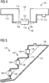
figure 4 est une illustration de principe d'un support selon un deuxième mode de réalisation de l'invention ; - La
figure 5 est une vue en coupe d'un dispositif de signalisation conforme au deuxième mode de réalisation ; - La
figure 6 est une vue en perspective d'un support conforme à un troisième mode de réalisation de l'invention.
- The
figure 1 is an illustration of a principle of a support according to a first embodiment of the invention; - The
figure 2 is an illustration of the LED present at thefigure 1 ; - The
figure 3 is a sectional view of a signaling device according to the first embodiment; - The
figure 4 is a basic illustration of a support according to a second embodiment of the invention; - The
figure 5 is a sectional view of a signaling device according to the second embodiment; - The
figure 6 is a perspective view of a support according to a third embodiment of the invention.
La
La face arrière du substrat 4 peut comprendre un ou plusieurs composants électriques ou électroniques 12.The rear face of the
Un élément optique 14 est disposé sur la face avant du substrat 4 de manière à coopérer avec les rayons lumineux émis par la LED. Cet élément optique peut être du type réfléchissant, absorbant ou encore diffusant, ou encore une combinaison de ces derniers.An
Contrairement à ce que la
Le matériau plastique du substrat peut être dopé en particules métalliques aptes à assurer l'accrochage de pistes métalliques sur sa surface extérieure. Cette technologie est couramment désignée par l'acronyme MID signifiant en langue anglaise « molded interconnect device ».The plastic material of the substrate may be doped with metal particles able to ensure the attachment of metal tracks on its outer surface. This technology is commonly referred to by the acronym MID meaning in English "molded interconnect device".
Les pistes électriques peuvent être réalisées par la technologie désignée par l'acronyme LDS signifiant en langue anglaise « Laser Direct Structuring ». Il s'agit de faire parcourir un rayon laser sur la surface correspondante du substrat, suivant la configuration des pistes à réaliser. Le rayon laser a pour effet de former une rugosité apte à favoriser l'accrochage. Cette étape est suivie d'une métallisation par trempage du substrat dans un ou plusieurs bains métalliques successifs.The electric tracks can be realized by the technology designated by the acronym LDS meaning in English "Laser Direct Structuring". This involves running a laser beam on the corresponding surface of the substrate, according to the configuration of the tracks to be made. The laser beam has the effect of forming a roughness capable of promoting attachment. This step is followed by a metallization by dipping the substrate in one or more successive metal baths.
Alternativement ou de manière complémentaire, les pistes électriques peuvent être réalisées par impression du type jet d'encre dont l'encre comprend des particules métalliques.Alternatively or in a complementary manner, the electrical tracks can be made by ink jet printing, the ink of which comprises metal particles.
Les pistes peuvent également être réalisées par un moulage en deux étapes du substrat, ou encore désigné « Two shot molding » en langue anglaise. Il s'agit d'un processus de moulage par injection en utilisant deux résines différentes où une seule des deux résines est métallisable. Typiquement, la résine métallisable est de l'ABS et la résine non-métallisable est du polycarbonate. Le substrat est ensuite soumis à un processus de dépôt auto-catalytique où du butadiène est utilisé pour chimiquement rendre la surface rugueuse et permettre l'adhérence d'une couche primaire de cuivre.The tracks can also be made by a two-stage molding of the substrate, or else designated "Two shot molding" in English. This is an injection molding process using two different resins where only one of the two resins is metallizable. Typically, the metallizable resin is ABS and the non-metallizable resin is polycarbonate. The substrate is then subjected to an auto-catalytic deposition process where butadiene is used to chemically roughen the surface and allow adhesion of a primary layer of copper.
En raison de la nature thermoplastique du substrat, l'utilisation de procédés de soudure classique pour les contacts électriques n'est pas adaptée. Les pattes de fixation et de connexion 8 de la LED sont ainsi fixées mécaniquement et électriquement par application d'une colle à base polymère et chargée en éléments métalliques. Il s'agit ainsi d'un procédé d'application dite « à froid » ne mettant pas à mal le substrat. Après polymérisation de la colle, celle-ci assure la fixation mécanique et électrique de la LED.Due to the thermoplastic nature of the substrate, the use of conventional soldering processes for electrical contacts is not suitable. The fixing and connecting
La
La
Le support 2 formé par le substrat 4 et les LED 6 qui y sont assemblées peut ainsi être mis en place directement sur les autres éléments du dispositif de signalisation.The
La
Le support 102 comprend un substrat 114 de forme non plane et assurant une fonction optique. Ce substrat 114 comprend des pistes électriques 110 sur sa face arrière. Il peut également comprendre un ou plusieurs composants électriques ou électroniques 112 sur sa face arrière, en connexion électrique avec les pistes électriques. Le substrat 114 comprend un orifice 116 au travers duquel est inséré, au moins partiellement, une LED 106. Celle-ci est de construction similaire à celle du premier mode de réalisation. Il s'agit d'un modèle de LED dit à montage inversé, c'est-à-dire destinée à être mise en place sur la face du substrat opposée à la face du côté de laquelle les rayons lumineux vont être émis. Le corps 118 de la LED 106 est ainsi inséré au travers de l'orifice 116 depuis la face arrière du substrat 114, de manière à ce que sa partie optique 120 regarde vers l'avant, c'est-à-dire du côté de la face avant du substrat 114. Lors de l'insertion de la LED 106, ses pattes 108 viennent en contact avec la face arrière du substrat 114, plus précisément avec les pistes électriques correspondantes 110. Le contact est assuré par de la colle dopée en métal. Cette colle est préférentiellement une colle de synthèse polymère, apte à polymériser après application à l'état pâteux. Il est fait référence à la description de la la fixation par colle du premier mode.The
Comme cela est visible à la
Afin d'assurer une fonction optique, le substrat 114 peut être recouvert, notamment sur sa face avant ou du moins sur des portions de sa face avant, d'un revêtement réfléchissant, absorbant ou diffusant. Ce revêtement peut être appliqué par différents procédés bien connus en soi de l'homme de métier, tels que par métallisation pour un revêtement réfléchissant, ou par application d'une peinture absorbante ou diffusante.In order to ensure an optical function, the
La
La
Ce troisième mode de réalisation est similaire au deuxième mode des
De manière générale, le substrat peut assurer d'autres fonctions telles que notamment celle d'un connecteur. Un connecteur peut en effet être moulé directement avec la matière du substrat. Il peut également comprendre un insert autour duquel la matière du substrat est moulée par injection. On peut également prévoir d'autres éléments sur le substrat assurant d'autres fonctions, comme notamment des pattes de fixation.In general, the substrate can perform other functions such as in particular that of a connector. A connector can in fact be molded directly with the material of the substrate. It may also include an insert around which the substrate material is injection molded. It is also possible to provide other elements on the substrate providing other functions, such as fixing tabs.
Claims (14)
le substrat (4 ; 114 ; 214) est une pièce moulée rigide présentant une forme en trois dimensions.Support (2; 102; 202) for a light source (s) for a light module (22; 122), particularly for a motor vehicle, comprising:
the substrate (4; 114; 214) is a rigid molded part having a three-dimensional shape.
le support (2 ; 102 ; 202) est conforme à l'une des revendications 1 à 11Signaling module comprising:
the support (2; 102; 202) is according to one of claims 1 to 11
Applications Claiming Priority (1)
| Application Number | Priority Date | Filing Date | Title |
|---|---|---|---|
| FR1457415A FR3024527B1 (en) | 2014-07-31 | 2014-07-31 | ELECTROLUMINESCENCE DIODE SUPPORT (LED) FOR SIGNALING MODULE |
Publications (1)
| Publication Number | Publication Date |
|---|---|
| EP3040611A1 true EP3040611A1 (en) | 2016-07-06 |
Family
ID=51519136
Family Applications (1)
| Application Number | Title | Priority Date | Filing Date |
|---|---|---|---|
| EP15178276.0A Withdrawn EP3040611A1 (en) | 2014-07-31 | 2015-07-24 | Support for light-emitting diodes (led) for signaling module |
Country Status (4)
| Country | Link |
|---|---|
| US (1) | US10246001B2 (en) |
| EP (1) | EP3040611A1 (en) |
| CN (1) | CN105318199A (en) |
| FR (1) | FR3024527B1 (en) |
Families Citing this family (4)
| Publication number | Priority date | Publication date | Assignee | Title |
|---|---|---|---|---|
| FR3030687B1 (en) * | 2014-12-19 | 2017-01-27 | Valeo Vision | ILLUMINATING AND / OR SIGNALING DEVICE COMPRISING A PLURALITY OF LIGHT EMITTING DIODES |
| JP6796764B2 (en) * | 2016-09-13 | 2020-12-09 | パナソニックIpマネジメント株式会社 | Mounting base, light emitting device, lighting device for moving body and moving body |
| KR102646632B1 (en) * | 2016-09-20 | 2024-03-12 | 삼성디스플레이 주식회사 | Display device |
| JP6543280B2 (en) * | 2017-01-31 | 2019-07-10 | 矢崎総業株式会社 | Display device |
Citations (9)
| Publication number | Priority date | Publication date | Assignee | Title |
|---|---|---|---|---|
| DE3545074A1 (en) * | 1985-12-19 | 1987-06-25 | Otto Maier Verlag Gmbh | Circuit for display and information purposes |
| US5331512A (en) | 1992-04-16 | 1994-07-19 | Orton Kevin R | Surface-mount LED |
| US20050243558A1 (en) | 2004-04-30 | 2005-11-03 | Guide Corporation | LED assembly with reverse circuit board |
| FR2876965A1 (en) * | 2004-10-26 | 2006-04-28 | Valeo Vision Sa | Light source e.g. smart LED, support for e.g. headlight of motor vehicle, has two conductors, each presenting respective bonding pad to be integrated by welding with respective conductors of each electronic support |
| WO2010058904A2 (en) * | 2008-11-18 | 2010-05-27 | 엘이디라이텍(주) | Lamp unit |
| US7924371B1 (en) | 2008-08-29 | 2011-04-12 | Rockwell Collins, Inc. | Multimode display for NVIS compatible operation |
| US20120112990A1 (en) * | 2010-11-10 | 2012-05-10 | Sheng-Chieh Chao | Light bar structure and display device |
| WO2013141509A1 (en) * | 2012-03-21 | 2013-09-26 | Lg Innotek Co., Ltd. | Printed circuit board and method of manufacturing the same |
| US20130329444A1 (en) * | 2012-06-08 | 2013-12-12 | Nam Seok Oh | Lamp unit and vehicle lamp apparatus using the same |
Family Cites Families (3)
| Publication number | Priority date | Publication date | Assignee | Title |
|---|---|---|---|---|
| KR101110865B1 (en) * | 2007-11-27 | 2012-02-15 | 엘이디라이텍(주) | Lamp unit |
| US8212342B2 (en) * | 2009-12-10 | 2012-07-03 | Stats Chippac Ltd. | Integrated circuit package system with removable backing element having plated terminal leads and method of manufacture thereof |
| US8988296B2 (en) * | 2012-04-04 | 2015-03-24 | Pulse Finland Oy | Compact polarized antenna and methods |
-
2014
- 2014-07-31 FR FR1457415A patent/FR3024527B1/en not_active Expired - Fee Related
-
2015
- 2015-07-24 EP EP15178276.0A patent/EP3040611A1/en not_active Withdrawn
- 2015-07-29 US US14/812,217 patent/US10246001B2/en not_active Expired - Fee Related
- 2015-07-31 CN CN201510463329.6A patent/CN105318199A/en active Pending
Patent Citations (9)
| Publication number | Priority date | Publication date | Assignee | Title |
|---|---|---|---|---|
| DE3545074A1 (en) * | 1985-12-19 | 1987-06-25 | Otto Maier Verlag Gmbh | Circuit for display and information purposes |
| US5331512A (en) | 1992-04-16 | 1994-07-19 | Orton Kevin R | Surface-mount LED |
| US20050243558A1 (en) | 2004-04-30 | 2005-11-03 | Guide Corporation | LED assembly with reverse circuit board |
| FR2876965A1 (en) * | 2004-10-26 | 2006-04-28 | Valeo Vision Sa | Light source e.g. smart LED, support for e.g. headlight of motor vehicle, has two conductors, each presenting respective bonding pad to be integrated by welding with respective conductors of each electronic support |
| US7924371B1 (en) | 2008-08-29 | 2011-04-12 | Rockwell Collins, Inc. | Multimode display for NVIS compatible operation |
| WO2010058904A2 (en) * | 2008-11-18 | 2010-05-27 | 엘이디라이텍(주) | Lamp unit |
| US20120112990A1 (en) * | 2010-11-10 | 2012-05-10 | Sheng-Chieh Chao | Light bar structure and display device |
| WO2013141509A1 (en) * | 2012-03-21 | 2013-09-26 | Lg Innotek Co., Ltd. | Printed circuit board and method of manufacturing the same |
| US20130329444A1 (en) * | 2012-06-08 | 2013-12-12 | Nam Seok Oh | Lamp unit and vehicle lamp apparatus using the same |
Also Published As
| Publication number | Publication date |
|---|---|
| CN105318199A (en) | 2016-02-10 |
| FR3024527B1 (en) | 2019-06-28 |
| FR3024527A1 (en) | 2016-02-05 |
| US10246001B2 (en) | 2019-04-02 |
| US20160031361A1 (en) | 2016-02-04 |
Similar Documents
| Publication | Publication Date | Title |
|---|---|---|
| EP2996142A1 (en) | Light source holder with integrated connector | |
| FR3024527B1 (en) | ELECTROLUMINESCENCE DIODE SUPPORT (LED) FOR SIGNALING MODULE | |
| EP2775197B1 (en) | Lighting and/or signalling device for a motor vehicle comprising a light guide | |
| EP4065882B1 (en) | Light module of a motor vehicle equipped with an optical element | |
| EP3755942A1 (en) | Signaling device for a motor vehicle | |
| EP2996202A1 (en) | Oled diode mounting with resilient connection strips | |
| EP2995851A1 (en) | Light module with led and oled diodes | |
| WO2016097322A1 (en) | Lighting and/or signalling device including a lightguide | |
| EP3537040B1 (en) | Luminous module and luminous device for motor vehicle comprising such a luminous module | |
| WO2017121944A1 (en) | Optical unit including a signaling light having a flat light guide projecting from the outer lens | |
| EP3270052A1 (en) | Lamp holder for a motor vehicle | |
| EP3194837A1 (en) | Substrate for a light module with metal strip used as shielding, a heat screen and/or an optical reflector | |
| EP3884206B1 (en) | Multi-functional light module provided with two flat light guides | |
| FR3056283A1 (en) | LIGHT DEVICE COMPRISING A SURFACE LIGHT SOURCE | |
| FR3088869A1 (en) | Device for pre-positioning and holding an element on a box | |
| EP3141805B1 (en) | Lighting system, in particular for a motor vehicle | |
| WO2022129456A1 (en) | Light guides connected by flexible links | |
| FR3104679A1 (en) | Optical part and light module for motor vehicle | |
| WO2023118567A1 (en) | Motor vehicle signalling device | |
| EP3881003A1 (en) | Headlamp unit for a motor vehicle with a protective shield attached to a frame | |
| FR3095849A1 (en) | Vehicle interior lighting device | |
| WO2023139131A1 (en) | Lighting device for a motor vehicle | |
| EP3803199A1 (en) | Motor vehicle optical unit and motor vehicle comprising such an element | |
| FR3085740A1 (en) | VEHICLE LIGHTING DEVICE HAVING THREE LIGHTING MODULES ACHIEVING A DRIVING LIGHT FUNCTION TOGETHER | |
| FR3036164A1 (en) | ICE FOR LIGHTING AND / OR SIGNALING DEVICE COMPRISING A MULTIFACET TRANSPARENT BODY AND DEVICE EQUIPPED WITH SUCH ICE |
Legal Events
| Date | Code | Title | Description |
|---|---|---|---|
| PUAI | Public reference made under article 153(3) epc to a published international application that has entered the european phase |
Free format text: ORIGINAL CODE: 0009012 |
|
| AK | Designated contracting states |
Kind code of ref document: A1 Designated state(s): AL AT BE BG CH CY CZ DE DK EE ES FI FR GB GR HR HU IE IS IT LI LT LU LV MC MK MT NL NO PL PT RO RS SE SI SK SM TR |
|
| AX | Request for extension of the european patent |
Extension state: BA ME |
|
| XX | Miscellaneous (additional remarks) |
Free format text: LES DESSINS 1-6 SONT DEPOSES CONFORMEMENT A LA REGLE 56(3) CBE. |
|
| STAA | Information on the status of an ep patent application or granted ep patent |
Free format text: STATUS: REQUEST FOR EXAMINATION WAS MADE |
|
| 17P | Request for examination filed |
Effective date: 20161216 |
|
| RBV | Designated contracting states (corrected) |
Designated state(s): AL AT BE BG CH CY CZ DE DK EE ES FI FR GB GR HR HU IE IS IT LI LT LU LV MC MK MT NL NO PL PT RO RS SE SI SK SM TR |
|
| STAA | Information on the status of an ep patent application or granted ep patent |
Free format text: STATUS: THE APPLICATION IS DEEMED TO BE WITHDRAWN |
|
| 18D | Application deemed to be withdrawn |
Effective date: 20210202 |