EP3040569A1 - Method for manufacturing shell-type needle bearing, and manufacturing jig used in manufacture of same - Google Patents
Method for manufacturing shell-type needle bearing, and manufacturing jig used in manufacture of same Download PDFInfo
- Publication number
- EP3040569A1 EP3040569A1 EP13892274.5A EP13892274A EP3040569A1 EP 3040569 A1 EP3040569 A1 EP 3040569A1 EP 13892274 A EP13892274 A EP 13892274A EP 3040569 A1 EP3040569 A1 EP 3040569A1
- Authority
- EP
- European Patent Office
- Prior art keywords
- retainer
- outer ring
- diameter
- shell outer
- jig
- Prior art date
- Legal status (The legal status is an assumption and is not a legal conclusion. Google has not performed a legal analysis and makes no representation as to the accuracy of the status listed.)
- Granted
Links
- 238000004519 manufacturing process Methods 0.000 title claims description 40
- 238000000034 method Methods 0.000 title abstract description 6
- 238000010438 heat treatment Methods 0.000 claims abstract description 18
- 238000003825 pressing Methods 0.000 claims description 27
- 238000003780 insertion Methods 0.000 claims description 19
- 230000037431 insertion Effects 0.000 claims description 19
- 238000005096 rolling process Methods 0.000 claims description 10
- 238000007747 plating Methods 0.000 abstract description 13
- 239000011347 resin Substances 0.000 abstract description 11
- 229920005989 resin Polymers 0.000 abstract description 11
- 239000000463 material Substances 0.000 abstract description 6
- 238000005452 bending Methods 0.000 description 5
- 230000000717 retained effect Effects 0.000 description 4
- 238000005255 carburizing Methods 0.000 description 3
- 238000005516 engineering process Methods 0.000 description 3
- 239000004033 plastic Substances 0.000 description 3
- 229920003023 plastic Polymers 0.000 description 3
- 229920000049 Carbon (fiber) Polymers 0.000 description 2
- 229910001209 Low-carbon steel Inorganic materials 0.000 description 2
- 239000004696 Poly ether ether ketone Substances 0.000 description 2
- 239000004734 Polyphenylene sulfide Substances 0.000 description 2
- 229910000831 Steel Inorganic materials 0.000 description 2
- 239000004917 carbon fiber Substances 0.000 description 2
- 238000005256 carbonitriding Methods 0.000 description 2
- 239000010960 cold rolled steel Substances 0.000 description 2
- 230000005489 elastic deformation Effects 0.000 description 2
- 239000003365 glass fiber Substances 0.000 description 2
- VNWKTOKETHGBQD-UHFFFAOYSA-N methane Chemical compound C VNWKTOKETHGBQD-UHFFFAOYSA-N 0.000 description 2
- 229920002530 polyetherether ketone Polymers 0.000 description 2
- 229920006324 polyoxymethylene Polymers 0.000 description 2
- 229920000069 polyphenylene sulfide Polymers 0.000 description 2
- 229920001343 polytetrafluoroethylene Polymers 0.000 description 2
- 239000004810 polytetrafluoroethylene Substances 0.000 description 2
- 239000010959 steel Substances 0.000 description 2
- RYGMFSIKBFXOCR-UHFFFAOYSA-N Copper Chemical compound [Cu] RYGMFSIKBFXOCR-UHFFFAOYSA-N 0.000 description 1
- 239000004677 Nylon Substances 0.000 description 1
- 229920003189 Nylon 4,6 Polymers 0.000 description 1
- 229920002292 Nylon 6 Polymers 0.000 description 1
- 229920002302 Nylon 6,6 Polymers 0.000 description 1
- 229930182556 Polyacetal Natural products 0.000 description 1
- 239000004952 Polyamide Substances 0.000 description 1
- 239000004760 aramid Substances 0.000 description 1
- 229920003235 aromatic polyamide Polymers 0.000 description 1
- 125000003118 aryl group Chemical group 0.000 description 1
- 230000005540 biological transmission Effects 0.000 description 1
- 239000013043 chemical agent Substances 0.000 description 1
- 229910052802 copper Inorganic materials 0.000 description 1
- 239000010949 copper Substances 0.000 description 1
- 238000005520 cutting process Methods 0.000 description 1
- 230000000694 effects Effects 0.000 description 1
- 230000005611 electricity Effects 0.000 description 1
- SQEHCNOBYLQFTG-UHFFFAOYSA-M lithium;thiophene-2-carboxylate Chemical compound [Li+].[O-]C(=O)C1=CC=CS1 SQEHCNOBYLQFTG-UHFFFAOYSA-M 0.000 description 1
- 238000012986 modification Methods 0.000 description 1
- 230000004048 modification Effects 0.000 description 1
- 229920001778 nylon Polymers 0.000 description 1
- 229920002647 polyamide Polymers 0.000 description 1
- 229920006122 polyamide resin Polymers 0.000 description 1
- -1 polytetrafluoroethylene Polymers 0.000 description 1
- 230000002787 reinforcement Effects 0.000 description 1
Images





Classifications
-
- F—MECHANICAL ENGINEERING; LIGHTING; HEATING; WEAPONS; BLASTING
- F16—ENGINEERING ELEMENTS AND UNITS; GENERAL MEASURES FOR PRODUCING AND MAINTAINING EFFECTIVE FUNCTIONING OF MACHINES OR INSTALLATIONS; THERMAL INSULATION IN GENERAL
- F16C—SHAFTS; FLEXIBLE SHAFTS; ELEMENTS OR CRANKSHAFT MECHANISMS; ROTARY BODIES OTHER THAN GEARING ELEMENTS; BEARINGS
- F16C33/00—Parts of bearings; Special methods for making bearings or parts thereof
- F16C33/30—Parts of ball or roller bearings
- F16C33/58—Raceways; Race rings
- F16C33/64—Special methods of manufacture
-
- C—CHEMISTRY; METALLURGY
- C21—METALLURGY OF IRON
- C21D—MODIFYING THE PHYSICAL STRUCTURE OF FERROUS METALS; GENERAL DEVICES FOR HEAT TREATMENT OF FERROUS OR NON-FERROUS METALS OR ALLOYS; MAKING METAL MALLEABLE, e.g. BY DECARBURISATION OR TEMPERING
- C21D1/00—General methods or devices for heat treatment, e.g. annealing, hardening, quenching or tempering
- C21D1/06—Surface hardening
-
- C—CHEMISTRY; METALLURGY
- C21—METALLURGY OF IRON
- C21D—MODIFYING THE PHYSICAL STRUCTURE OF FERROUS METALS; GENERAL DEVICES FOR HEAT TREATMENT OF FERROUS OR NON-FERROUS METALS OR ALLOYS; MAKING METAL MALLEABLE, e.g. BY DECARBURISATION OR TEMPERING
- C21D9/00—Heat treatment, e.g. annealing, hardening, quenching or tempering, adapted for particular articles; Furnaces therefor
- C21D9/40—Heat treatment, e.g. annealing, hardening, quenching or tempering, adapted for particular articles; Furnaces therefor for rings; for bearing races
-
- F—MECHANICAL ENGINEERING; LIGHTING; HEATING; WEAPONS; BLASTING
- F16—ENGINEERING ELEMENTS AND UNITS; GENERAL MEASURES FOR PRODUCING AND MAINTAINING EFFECTIVE FUNCTIONING OF MACHINES OR INSTALLATIONS; THERMAL INSULATION IN GENERAL
- F16C—SHAFTS; FLEXIBLE SHAFTS; ELEMENTS OR CRANKSHAFT MECHANISMS; ROTARY BODIES OTHER THAN GEARING ELEMENTS; BEARINGS
- F16C19/00—Bearings with rolling contact, for exclusively rotary movement
- F16C19/22—Bearings with rolling contact, for exclusively rotary movement with bearing rollers essentially of the same size in one or more circular rows, e.g. needle bearings
- F16C19/44—Needle bearings
- F16C19/46—Needle bearings with one row or needles
- F16C19/466—Needle bearings with one row or needles comprising needle rollers and an outer ring, i.e. subunit without inner ring
-
- F—MECHANICAL ENGINEERING; LIGHTING; HEATING; WEAPONS; BLASTING
- F16—ENGINEERING ELEMENTS AND UNITS; GENERAL MEASURES FOR PRODUCING AND MAINTAINING EFFECTIVE FUNCTIONING OF MACHINES OR INSTALLATIONS; THERMAL INSULATION IN GENERAL
- F16C—SHAFTS; FLEXIBLE SHAFTS; ELEMENTS OR CRANKSHAFT MECHANISMS; ROTARY BODIES OTHER THAN GEARING ELEMENTS; BEARINGS
- F16C33/00—Parts of bearings; Special methods for making bearings or parts thereof
- F16C33/30—Parts of ball or roller bearings
- F16C33/46—Cages for rollers or needles
- F16C33/4617—Massive or moulded cages having cage pockets surrounding the rollers, e.g. machined window cages
- F16C33/4623—Massive or moulded cages having cage pockets surrounding the rollers, e.g. machined window cages formed as one-piece cages, i.e. monoblock cages
- F16C33/4635—Massive or moulded cages having cage pockets surrounding the rollers, e.g. machined window cages formed as one-piece cages, i.e. monoblock cages made from plastic, e.g. injection moulded window cages
-
- F—MECHANICAL ENGINEERING; LIGHTING; HEATING; WEAPONS; BLASTING
- F16—ENGINEERING ELEMENTS AND UNITS; GENERAL MEASURES FOR PRODUCING AND MAINTAINING EFFECTIVE FUNCTIONING OF MACHINES OR INSTALLATIONS; THERMAL INSULATION IN GENERAL
- F16C—SHAFTS; FLEXIBLE SHAFTS; ELEMENTS OR CRANKSHAFT MECHANISMS; ROTARY BODIES OTHER THAN GEARING ELEMENTS; BEARINGS
- F16C43/00—Assembling bearings
- F16C43/04—Assembling rolling-contact bearings
-
- F—MECHANICAL ENGINEERING; LIGHTING; HEATING; WEAPONS; BLASTING
- F16—ENGINEERING ELEMENTS AND UNITS; GENERAL MEASURES FOR PRODUCING AND MAINTAINING EFFECTIVE FUNCTIONING OF MACHINES OR INSTALLATIONS; THERMAL INSULATION IN GENERAL
- F16C—SHAFTS; FLEXIBLE SHAFTS; ELEMENTS OR CRANKSHAFT MECHANISMS; ROTARY BODIES OTHER THAN GEARING ELEMENTS; BEARINGS
- F16C43/00—Assembling bearings
- F16C43/04—Assembling rolling-contact bearings
- F16C43/06—Placing rolling bodies in cages or bearings
-
- F—MECHANICAL ENGINEERING; LIGHTING; HEATING; WEAPONS; BLASTING
- F16—ENGINEERING ELEMENTS AND UNITS; GENERAL MEASURES FOR PRODUCING AND MAINTAINING EFFECTIVE FUNCTIONING OF MACHINES OR INSTALLATIONS; THERMAL INSULATION IN GENERAL
- F16C—SHAFTS; FLEXIBLE SHAFTS; ELEMENTS OR CRANKSHAFT MECHANISMS; ROTARY BODIES OTHER THAN GEARING ELEMENTS; BEARINGS
- F16C33/00—Parts of bearings; Special methods for making bearings or parts thereof
- F16C33/30—Parts of ball or roller bearings
- F16C33/46—Cages for rollers or needles
- F16C33/467—Details of individual pockets, e.g. shape or roller retaining means
- F16C33/4676—Details of individual pockets, e.g. shape or roller retaining means of the stays separating adjacent cage pockets, e.g. guide means for the bearing-surface of the rollers
-
- F—MECHANICAL ENGINEERING; LIGHTING; HEATING; WEAPONS; BLASTING
- F16—ENGINEERING ELEMENTS AND UNITS; GENERAL MEASURES FOR PRODUCING AND MAINTAINING EFFECTIVE FUNCTIONING OF MACHINES OR INSTALLATIONS; THERMAL INSULATION IN GENERAL
- F16C—SHAFTS; FLEXIBLE SHAFTS; ELEMENTS OR CRANKSHAFT MECHANISMS; ROTARY BODIES OTHER THAN GEARING ELEMENTS; BEARINGS
- F16C43/00—Assembling bearings
- F16C43/04—Assembling rolling-contact bearings
- F16C43/06—Placing rolling bodies in cages or bearings
- F16C43/065—Placing rolling bodies in cages or bearings in cages
-
- F—MECHANICAL ENGINEERING; LIGHTING; HEATING; WEAPONS; BLASTING
- F16—ENGINEERING ELEMENTS AND UNITS; GENERAL MEASURES FOR PRODUCING AND MAINTAINING EFFECTIVE FUNCTIONING OF MACHINES OR INSTALLATIONS; THERMAL INSULATION IN GENERAL
- F16C—SHAFTS; FLEXIBLE SHAFTS; ELEMENTS OR CRANKSHAFT MECHANISMS; ROTARY BODIES OTHER THAN GEARING ELEMENTS; BEARINGS
- F16C43/00—Assembling bearings
- F16C43/04—Assembling rolling-contact bearings
- F16C43/06—Placing rolling bodies in cages or bearings
- F16C43/08—Placing rolling bodies in cages or bearings by deforming the cages or the races
Definitions
- the present invention relates to a method of manufacturing a shell type needle roller bearing and a manufacturing jig used for the manufacturing thereof, and particularly, to a method of manufacturing a shell type needle roller bearing used in rotation support portions of various pieces of machinery, and a manufacturing jig used for the manufacturing thereof.
- a shell type needle roller bearing 100 includes a shell outer ring 101 having an inner circumferential raceway surface 101a and a pair of flange portions 101b and 101c in both end portions of the shell outer ring 101; a plurality of needles 102 that are disposed in the shell outer ring 101 in such a way as to be capable of rolling along the raceway surface 101a; and a retainer 103 having a plurality of pockets for retaining the plurality of needles 102.
- one flange portion 101 b is formed by processing a typical cold rolled steel sheet (for example, which is made of low carbon steel such as SPCC) into the shape of a cup by deep drawing, and blanking a bottom surface.
- Plating such as copper plating is applied to edge portions on axial opening sides of the shell outer ring 101, and a heat treatment such as a carburizing treatment or a carbonitriding treatment is applied to the shell outer ring 101.
- the needles 102 and the retainer 103 are assembled with the shell outer ring 101, the plating of which is peeled off, and the flange portion 101c is formed by bending the edge portions on the axial opening sides of the shell outer ring 101.
- the shell type needle roller bearing 100 is manufactured.
- This manufacturing method has a problem in that not only is the number of steps large, a large amount of process time is required, or an equipment cost is high, but also transportation between the steps and the like has to be taken into consideration.
- the manufacturing method has a problem in that various chemical agents have to be used to peel the plating off.
- Patent Document 1 discloses hot curling technology by which bending is performed while heating the flange portion 101c using high frequency electricity so as to eliminate the plating step.
- Patent Document 2 discloses technology by which the shell type needle roller bearing is assembled without a heat treatment being applied thereto, and a carburizing treatment is applied to the entirety of the assembled shell type needle roller bearing at the final stage.
- the present invention is made in light of these problems, and an object of the present invention is to provide a method of manufacturing a shell type needle roller bearing with a resin retainer which can be manufactured by a manufacturing method not requiring a plating step, and a manufacturing jig used for the manufacturing thereof.
- the retainer and the needles are assembled with the shell outer ring, and thus a plating step, which has been required in the related art, is not required, and the retainer is not thermally affected by the heat treatment. Therefore, resin can be used as the material of the retainer.
- a shell type needle roller bearing 10 includes a shell outer ring 11 having an inner circumferential raceway surface 11a and a pair of inward flange portions 11b and 11c in both end portions of the shell outer ring 11; a plurality of needles 12 that are disposed in the shell outer ring 11 in such a way as to be capable of rolling along the raceway surface 11a of the shell outer ring 11; and a retainer 13 having a plurality of pockets 14 for retaining the plurality of needles 12.
- a shaft (or an inner ring member) (not illustrated) is rotatably supported by the shell type needle roller bearing 10.
- the shell outer ring 11 is manufactured by the plastic working (for example, deep drawing) of a cold rolled steel sheet (for example, which is made of low carbon steel such as SPCC) or the like such that the pair of flange portions 11b and 11c is bent and formed in both end portions of the shell outer ring 11 with a cylindrical shape in its entirety.
- the shell outer ring 11 is hardened by a heat treatment such as a carburizing treatment or a carbonitriding treatment.
- the flange portions 11b and 11c are formed in the shell outer ring 11, and the shell outer ring 11 is hardened by a heat treatment.
- the shell outer ring 11 can also be formed by cutting a thick steel sheet instead of the plastic working of a thin steel sheet.
- the retainer 13 includes a pair of coaxially disposed rim portions 15, 15, and a plurality of columnar portions 16 that connect the pair of rim portions 15, 15 together in an axial direction.
- Each of the pair of rim portions 15, 15 is formed of a plurality (four in the embodiment) of arc-shaped portions 15a.
- a plurality of slits 15c are formed in the rim portions 15, 15 while being positioned at the same circumferential phase, and each of the slits 15c is formed between end portions 15b, 15b of the arc-shaped portions 15a that are circumferentially adjacent to each other.
- a large number of the slits 15c decrease the number of needles 12, and thus, preferably, the number of slits 15c is two to six.
- a plurality of elastic deformable portions 17 are circumferentially provided in the retainer 13 such that the retainer 13 (the slits 15c) is allowed to circumferentially contract, and each of the elastic deformable portions 17 is provided in a region between the columnar portions 16, 16 that are circumferentially adjacent to each other, with the slits 15c being formed in the region.
- Each of the pockets 14, 14 is formed by a rectangular space, the circumference of which is surrounded by facing inner surfaces of the pair of rim portions 15, 15, and both circumferential side surfaces of the columnar portions 16, 16 that are circumferentially adjacent to each other without the elastic deformable portion 17 being interposed therebetween.
- radially inside locking protrusions 16a, 16a are respectively formed in diametrical inner end portions of the retainer 13 and on both the circumferential side surfaces of the columnar portions 16, 16 over the entire length of the columnar portions 16, 16.
- the elastic deformable portion 17 includes a pair of elastic deformable pieces 17a, 17a, portions of which respectively extend axially inwards from end portions (base end portions) 15b, 15b of the arc-shaped portions 15a, 15a circumferentially adjacent to each other, and the extended portions of which are connected together in the circumferential direction.
- the pair of elastic deformable pieces 17a, 17a has the same shape, and the elastic deformable portion 17 is formed symmetrical relative to an axial center portion C of the retainer 13.
- the elastic deformable piece 17a is formed of a plurality of arcs 17a1, 17a2, and 17a3 which respectively have radii of curvature R1 to R3.
- the elastic deformable piece 17a may be formed of a single arc.
- an axial width w1 of the end portion (which is the base end portion of the elastic deformable portion 17) 15b of the arc-shaped portion 15a is preferably greater than or equal to an axial width w2 of the arc-shaped portion 15a.
- An arc surface, which is formed on an axial inner surface of the base end portion, preferably has a large curvature (radius of curvature r is preferably small).
- a radial thickness h of the elastic deformable piece 17a is set to be greater than a width w3 of the elastic deformable piece 17a, and thus it is possible to restrict the elastic deformable piece 17a from being radially deformed as illustrated by the arrow.
- Fig. 6A illustrates sectional views of the retainer 13 and the shell outer ring 11 which are not yet elastically deformed
- Fig. 6B is a side view when the retainer 13 and the shell outer ring 11 are seen in a direction of arrow V in Fig. 6A
- Fig. 7A illustrates sectional views of the retainer 13 and the shell outer ring 11 which are elastically deformed
- Fig. 7B is a side view when the retainer 13 and the shell outer ring 11 are seen in a direction of arrow VI in Fig. 7A .
- An outer diameter ⁇ D1n of the retainer 13 is greater than an inner diameter (hereinafter, which is referred to as a flange-portion inner diameter) ⁇ D2 of the pair of inward flange portions 11b and 11c of the shell outer ring 11 ( ⁇ D1n > ⁇ D2).
- a circumferential distance L1 (refer to Fig. 2 ) of each of the slits 15c is reduced by deforming the elastic deformable portion 17, and as a result, the diameter of the retainer 13 can be circumferentially reduced. Accordingly, as illustrated in Fig.
- the diameter of the retainer 13 can be reduced up to an outer diameter ⁇ D1s that is smaller than the flange-portion inner diameter ⁇ D2 of the shell outer ring 11 ( ⁇ D2 > ⁇ D1s).
- a relationship between the sum of the outer circumferential length of the retainer 15 and the circumferential distances L1 of the slits 15c and the inner circumferential length of the inward flange portions 11b and 11c of the shell outer ring 11 is substantially represented by an expression hereinbelow.
- the movable range of the elastic deformable piece 17a that is, the amount of deformation of the elastic deformable piece 17a can be arbitrarily set by using an axial distance L3 (refer to Fig. 3 ) between the pair of elastic deformable pieces 17a, 17a, and the circumferential distance L1 of the slit 15c.
- the circumferential distance L1 of the slit 15c which is not yet elastically deformed is set to be smaller than the sum of the circumferential distances L2, L2 between the columnar portions 16 and the elastic deformable pieces 17a adjacent to each other in such a way that the columnar portion 16 is prevented from coming into contact with the elastic deformable piece 17a before the slit 15c disappears (L1 ⁇ 2 x L2).
- the outer diameter of the retainer 13 is reduced until becoming smaller than the flange-portion inner diameter ⁇ D2 of the shell outer ring 11, and the retainer 13 is inserted into the shell outer ring 11. After the insertion, the elastic deformable portions 17 are restored to the original state, and as a result, the retainer 13 is accommodated in the shell outer ring 11.
- retainer insertion jigs formed of a female jig 21 and a male jig 26 are used to reduce the diameter of the retainer 13 and to insert the retainer 13 into the shell outer ring 11.
- the shell outer ring-mounting stepped portion 22 has a diameter slightly greater than an outer diameter ⁇ D3 of the shell outer ring 11, and is axially concave.
- a retainer-mounting stepped portion 25, in which the retainer 13 can be mounted, is provided at the other axial end (upper end in Fig. 8 ) of the female jig 21.
- the retainer-mounting stepped portion 25 is coaxial with the shell outer ring-mounting stepped portion 22, has a diameter slightly greater than the outer diameter ⁇ D1n of the retainer 13, and is axially concave.
- a small-diameter hole 23 is provided on an inside end surface of the shell outer ring-mounting stepped portion 22.
- the small-diameter hole 23 is coaxial with the shell outer ring-mounting stepped portion 22, and has a diameter smaller than the flange-portion inner diameter ⁇ D2 of the shell outer ring 11.
- the small-diameter hole 23 is gradually connected to the retainer-mounting stepped portion 25 via a reduced diameter hole 24 with a tapered shape, the diameter of which increases from the small-diameter hole 23 toward the retainer-mounting stepped portion 25.
- the male jig 26 includes a cylindrical body portion 27, and a cylindrical retainer mounting portion 28 that is coaxial with the body portion 27, and protrudes toward one end side (lower side in Fig. 8 ) in the axial direction while being adjacent to the body portion 27.
- the body portion 27 is set to have a diameter slightly smaller than the small-diameter hole 23 of the female jig 21, and the body portion 27 can be inserted into the small-diameter hole 23.
- the retainer mounting portion 28 is formed to have a diameter that is slightly smaller than a diameter obtained by subtracting two times the radial thickness h (refer to Fig. 5 ) of the retainer 13 from the diameter of the small-diameter hole 23.
- a stepped portion between the body portion 27 and the retainer mounting portion 28 serves as a retainer pressing portion 29 that is a flat surface perpendicular to the axial direction (flat surface perpendicular to the axis).
- a pressing shaft 20 is provided on the body portion 27 side (the other end side in the axial direction and the upper side in Fig. 8 ) of the male jig 26, with the body portion 27 side being opposite to the retainer mounting portion 28.
- the pressing shaft 20 transmits an axial pressing force from a hand or a machine toward the male jig 26.
- the shape of the pressing shaft 20 may be selected so as to allow the pressing shaft 20 to be easily gripped by an operator, or to be easily attached to a machine, and the pressing shaft 20 does not necessarily have the shape illustrated in Fig. 8 .
- the shell outer ring 11 is mounted in the shell outer ring-mounting stepped portion 22 of the female jig 21.
- the retainer 13 is mounted in the retainer mounting portion 28 of the male jig 26, or as illustrated in Fig. 9B , the retainer 13 is mounted in the retainer-mounting stepped portion 25 of the female jig 21.
- the male jig 26 is inserted into the female jig 21 from the retainer-mounting stepped portion 25 side of the female jig 21.
- the retainer 13 is axially pressed by the retainer pressing portion 29 of the male jig 26, and is pressed into the female jig 21 while the diameter of the retainer 13 is being reduced by the reduced diameter hole 24 of the female jig 21.
- the retainer mounting portion 28 of the male jig 26 backs up the retainer 13 such that the retainer 13 is prevented from being abnormally deformed.
- the diameter of the retainer 13 is restored to the original outer diameter ⁇ D1n, and the retainer 13 is prevented from falling off the shell outer ring 11.
- the needles 12, 12 are respectively inserted into the pockets 14, 14 of the retainer 13 from the radial inside of the retainer 13. During the insertion operation, the needles 12 are respectively pressed into the pockets 14, 14 while the columnar portions 16, 16 and the radially inside locking protrusions 16a are elastically deformed, with both circumferential sides of the pockets 14, 14 being partitioned off by the columnar portions 16, 16, and the radially inside locking protrusions 16a being respectively formed on the side surfaces of the columnar portions 16, 16.
- a circumferential width Wp between portions of the pocket 14 is greater than an outer diameter ⁇ Dk of the needle 12 (Wp > ⁇ Dk), in the portions deviating from the locking protrusions 16a, and thus the needle 12 is allowed to roll in the pocket 14 by a small force while being retained in the pocket 14.
- a gap Wi which is between free-state tip edges of the pair of radially inside locking protrusions 16a, 16a that is present in radially inside opening portions of the pockets 14, 14, is smaller than the outer diameter ⁇ Dk of the needle 12 ⁇ Dk > Wi),. Accordingly, the needles 12 retained in the pockets 14, 14 are prevented from unexpectedly falling off the pockets 14, 14.
- a retainer 18 is only the difference among the configuration elements of the shell type needle roller bearing. Due to the retainer 18, a different female jig 31 and a different male jig 36 are used.
- the radially inside locking protrusions 16a, 16a are respectively formed in the diametrical inner end portions of the retainer 13 over the entire length of the columnar portions 16, 16, and on both the circumferential side surfaces of the columnar portions 16, 16.
- radially outside locking protrusions 16b, 16b are respectively formed in outer end portions of the retainer 18 which is used in this assembly method over the entire length of the columnar portions 16, 16.
- the retainer 18 has the same configuration as the retainer 13 except that each portion has a different dimension, and a description will be given on the condition that the same reference signs are assigned to the same configuration elements.
- the plurality of needles 12, 12 are respectively inserted into the pockets 14, 14 from the radial inside or the radial outside of the retainer 18.
- the needles 12 are respectively pressed into the pockets 14, 14 while the columnar portions 16, 16 and the radially inside locking protrusions 16a or the radially outside locking protrusions 16b are elastically deformed, with both the circumferential sides of the pockets 14, 14 being partitioned off by the columnar portions 16, 16, and the radially inside locking protrusions 16a or the radially outside locking protrusions 16b being respectively formed on the side surfaces of the columnar portions 16, 16.
- the circumferential width Wp between the portions of the pocket 14, 14 is greater than the outer diameter ⁇ Dk of the needle 12 (Wp > ⁇ Dk), in the portions deviating from the locking protrusions 16a, 16a, and thus the needle 12 is allowed to roll in the pocket 14 by a small force while being retained in the pocket 14.
- the gap Wi which is between the free-state tip edges of the pair of radially inside locking protrusions 16a, 16a that is present in radially inside opening portions of the pockets 14, 14, and a gap Wo, which is between free-state tip edges of the pair of radially outside locking protrusions 16b, 16b that is present in the radially outside opening portions, are smaller than the outer diameter ⁇ Dk of the needle 12 ( ⁇ Dk > Wi and ⁇ Dk > Wo). Accordingly, the plurality of needles 12, 12 retained in the pockets 14, 14 are prevented from unexpectedly falling off the pockets 14, 14.
- the plurality of needles 12, 12 are assembled with the retainer 18, and thereafter, similar to the retainer 13, the diameter of the retainer 18 is reduced, and the retainer 18 is assembled with the shell outer ring 11. For this reason, a subassembly obtained by assembling the plurality of needles 12, 12 into the retainer 18 is handled as a unit, and thus it is possible to increase the degree of freedom in the assembly step.
- the outer diameter ⁇ D1n of the retainer 18 is greater than the flange-portion inner diameter ⁇ D2 of the shell outer ring 11.
- a circumferential distance L4 of each of the slit 15c is reduced by deforming the elastic deformable portion 17, and as a result, the diameter of the retainer 18 can be circumferentially reduced.
- Fig. 12A is a view illustrating the retainer 18 with which the plurality of needles 12, 12 are assembled
- Fig. 12B is a view illustrating a state in which the diameter of the retainer 18 having the plurality of needles 12, 12 assembled therewith is reduced due to elastic deformation.
- the maximum outer diameter of the retainer 18 having the plurality of needles 12, 12 assembled therewith can be reduced up to an outer diameter ⁇ D4s that is smaller than the flange-portion inner diameter ⁇ D2 of the shell outer ring 11.
- the maximum outer diameter of the retainer 18 having the plurality of needles 12, 12 assembled therewith is reduced to be smaller than the flange-portion inner diameter ⁇ D2 of the shell outer ring 11, and the retainer 18 is inserted into the shell outer ring 11. After the insertion, the elastic deformable portions 17 is restored to the original state, and as a result, the retainer 18 is accommodated in the shell outer ring 11.
- retainer insertion jigs formed of the female jig 31 and the male jig 36 are used to reduce the diameter of the retainer 18 having the plurality of needles 12, 12 assembled therewith, and to insert the retainer 18 into the shell outer ring 11.
- the female jig 21 is the same as the female jig 31
- the male jig 26 is the same as the male jig 36 except that each portion has a different dimension, and a description will be given on the condition that the same reference signs are assigned to the same configuration elements.
- the shell outer ring-mounting stepped portion 22, in which the shell outer ring 11 can be mounted, is provided at one axial end (lower end in Fig. 8 ) of the female jig 31.
- the shell outer ring-mounting stepped portion 22 has a diameter slightly greater than the outer diameter ⁇ D3 of the shell outer ring 11, and is axially concave.
- a retainer-mounting stepped portion 35 is provided at the other axial end (upper end in Fig. 8 ) of the female jig 31.
- the retainer-mounting stepped portion 35 is coaxial with the shell outer ring-mounting stepped portion 22, and is axially concave.
- the diameter of the retainer-mounting stepped portion 35 is slightly greater than the maximum outer diameter ⁇ D4n (refer to Fig. 12A ) of the retainer 18 with which the plurality of needles 12, 12 are assembled, and thus it is possible to mount the retainer 13 with which the plurality of needles 12, 12 are assembled.
- the small-diameter hole 23 is provided on the inside end surface of the shell outer ring-mounting stepped portion 22.
- the small-diameter hole 23 is coaxial with the shell outer ring-mounting stepped portion 22, and has a diameter smaller than the flange-portion inner diameter ⁇ D2 of the shell outer ring 11.
- the small-diameter hole 23 is gradually connected to the retainer-mounting stepped portion 35 via a reduced diameter hole 34 with a tapered shape, the diameter of which increases from the small-diameter hole 23 toward the retainer-mounting stepped portion 35.
- the male jig 36 includes the cylindrical body portion 27, and a retainer mounting portion 38 that is coaxial with the body portion 27, and protrudes toward one end side (lower side in Fig. 8 ) in the axial direction while being adjacent to the body portion 27.
- the body portion 27 is set to have a diameter slightly smaller than the small-diameter hole 23 of the female jig 31, and the body portion 27 can be inserted into the small-diameter hole 23.
- the retainer mounting portion 38 is formed to have a diameter that is slightly smaller than a diameter obtained by subtracting two times the outer diameter ⁇ Dk (refer to Fig. 11 ) of the needle 12 from the diameter of the small-diameter hole 23.
- a stepped portion between the body portion 27 and the retainer mounting portion 38 serves as a retainer pressing portion 39 that is a flat surface perpendicular to the axial direction (flat surface perpendicular to the axis).
- the pressing shaft 20 is provided on the body portion 27 side (the other end side in the axial direction and the upper side in Fig. 8 ) of the male jig 36, with the body portion 27 side being opposite to the retainer mounting portion 38.
- the pressing shaft 20 transmits an axial pressing force from a hand or a machine toward the male jig 36.
- the shape of the pressing shaft 20 may be selected so as to allow the pressing shaft 20 to be easily gripped by an operator, or to be easily attached to a machine, and the pressing shaft 20 does not necessarily have the shape illustrated in Fig. 8 .
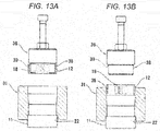
- the shell outer ring 11 is mounted in the shell outer ring-mounting stepped portion 22 of the female jig 31.
- the retainer 18 having the plurality of needles 12, 12 assembled therewith is mounted in the retainer-mounting stepped portion 35 of the male jig 26, or is mounted in the retainer mounting portion 38 of the male jig 36.
- the male jig 36 is inserted into the female jig 31 from the retainer-mounting stepped portion 35 side of the female jig 31.
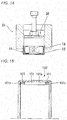
- the retainer 18 is axially pressed by the retainer pressing portion 39 of the male jig 36, and is pressed into the female jig 31 while the diameter of the retainer 18 is being reduced by the reduced diameter hole 34 of the female jig 31. At this time, the retainer mounting portion 38 of the male jig 36 backs up the retainer 18 such that the retainer 18 is prevented from being abnormally deformed. As illustrated in Fig. 14 , when the retainer 18 is inserted into the inside of the shell outer ring 11, the diameter of the retainer 18 is restored to the original outer diameter ⁇ D1n, and the retainer 8 is prevented from falling off the shell outer ring 11.
- the retainers 13 and 18 are made of resin, and the following resin can be used as the material of the retainers 13 and 18: polyamide (nylon resin) such as aromatic polyamide (aromatic PA), polyamide 46, polyamide 6, polyamide 66; fluororesin such as polyphenylene sulfide (PPS), polyetheretherketone (PEEK), polyacetal (POM), polytetrafluoroethylene (PTFE); and the like.
- a reinforcement such as glass fiber or carbon fiber is mixed. More preferably, 5% by weight to 30% by weight of glass fiber or carbon fiber may be mixed in the polyamide resin, and thus bending elastic modulus may be set to 2000 MPa to 5000 MPa. When the bending elastic modulus is within this range, more preferably, the deformable portion is capable of having deformability and necessary rigidity.
- the radially inside locking protrusion 16a and the radially outside locking protrusion 16b are formed over the entire length of each of the columnar portions 16, 16; however, the radially inside locking protrusion 16a and the radially outside locking protrusion 16b may be provided only in a range shorter than the entire length, or may be provided while being divided into a plurality of pieces.
- the plurality of elastic deformable portions 17 are circumferentially provided in each of the retainers 13 and 18 so as to allow each of the retainers 13 and 18 to circumferentially contract, and the elastic deformable portion 17 is formed symmetrical relative to the axial center portion C. Therefore, it is possible to provide the retainers 13 and 18 which are prevented from undergoing plastic deformation, have sufficient strength against axial twist, and are capable of circumferentially contracting while a sufficient amount of deformation is ensured. The motion of the needle 12 is appropriately allowed, and the fretting of the needle 12 can be prevented by the elastic deformable portion 17.
- Each of the pair of rim portions 15, 15 is formed of the plurality of arc-shaped portions 15a.
- the plurality of slits 15c are formed in the pair of rim portions 15, 15 while being positioned at the same circumferential phase, and each of the slits 15c is formed between the end portions 15b of the arc-shaped portions 15a that are circumferentially adjacent to each other.
- the elastic deformable portion 17 includes the pair of elastic deformable pieces 17a, 17a, portions of which respectively extend axially inwards from the end portions 15b of the arc-shaped portions 15a circumferentially adjacent to each other, and the extended portions of which are connected together in the circumferential direction. Accordingly, it is possible to form the elastic deformable portion 17 that is symmetrical relative to the axial center portion C.
- the elastic deformable portion 17 is formed between the columnar portions 16, 16 adjacent to each other in the circumferential direction, and the circumferential distance L1 of the slit 15c is smaller than the sum of the circumferential distances L2 between the columnar portions 16 and the elastic deformable pieces 17a adjacent to each other. Therefore, it is possible to ensure a sufficient amount of deformation without the columnar portion 16 coming into contact with the elastic deformable piece 17a before the slit 15c disappears when the elastic deformable portion 17 circumferentially contract.
- the retainer and the needles are assembled with the shell outer ring, and thus a plating step, which has been required in the related art, is not required, and the retainer is not thermally affected by the heat treatment. Therefore, resin can be used as the material of the retainer, and this manufacturing method can be preferably adopted as a method of manufacturing a shell type needle roller bearing used in rotation support portions of various pieces of machinery.
Landscapes
- Engineering & Computer Science (AREA)
- General Engineering & Computer Science (AREA)
- Mechanical Engineering (AREA)
- Chemical & Material Sciences (AREA)
- Crystallography & Structural Chemistry (AREA)
- Thermal Sciences (AREA)
- Physics & Mathematics (AREA)
- Materials Engineering (AREA)
- Metallurgy (AREA)
- Organic Chemistry (AREA)
- Manufacturing & Machinery (AREA)
- Rolling Contact Bearings (AREA)
- Mounting Of Bearings Or Others (AREA)
Abstract
Description
- The present invention relates to a method of manufacturing a shell type needle roller bearing and a manufacturing jig used for the manufacturing thereof, and particularly, to a method of manufacturing a shell type needle roller bearing used in rotation support portions of various pieces of machinery, and a manufacturing jig used for the manufacturing thereof.
- In recent years, instead of a slide bearing (bush), a shell type needle roller bearing having the same sectional height as the slide bearing is used in portions, which receive a radial load, of an automatic transmission and the like of an automobile. As illustrated in
Fig. 15 , a shell type needle roller bearing 100 includes a shellouter ring 101 having an innercircumferential raceway surface 101a and a pair offlange portions outer ring 101; a plurality ofneedles 102 that are disposed in the shellouter ring 101 in such a way as to be capable of rolling along theraceway surface 101a; and aretainer 103 having a plurality of pockets for retaining the plurality ofneedles 102. - In a step of forming the shell
outer ring 101 according to a method of manufacturing the shell type needle roller bearing 100 in the related art, oneflange portion 101 b is formed by processing a typical cold rolled steel sheet (for example, which is made of low carbon steel such as SPCC) into the shape of a cup by deep drawing, and blanking a bottom surface. Plating such as copper plating is applied to edge portions on axial opening sides of the shellouter ring 101, and a heat treatment such as a carburizing treatment or a carbonitriding treatment is applied to the shellouter ring 101. Thereafter, theneedles 102 and theretainer 103 are assembled with the shellouter ring 101, the plating of which is peeled off, and theflange portion 101c is formed by bending the edge portions on the axial opening sides of the shellouter ring 101. As a result, the shell type needle roller bearing 100 is manufactured. - When the plating step, the heat treatment step, the plating peeling off step, and the assembly/press step are sequentially performed after the press step, it is difficult to set these steps on the same line. This manufacturing method has a problem in that not only is the number of steps large, a large amount of process time is required, or an equipment cost is high, but also transportation between the steps and the like has to be taken into consideration. In addition, the manufacturing method has a problem in that various chemical agents have to be used to peel the plating off.
- Patent Document 1 discloses hot curling technology by which bending is performed while heating the
flange portion 101c using high frequency electricity so as to eliminate the plating step. -
Patent Document 2 discloses technology by which the shell type needle roller bearing is assembled without a heat treatment being applied thereto, and a carburizing treatment is applied to the entirety of the assembled shell type needle roller bearing at the final stage. -
- Patent Document I:
JP-A-11-303863 - Patent Document 2:
JP-A-2002-139067 - According to the technology disclosed in
Citations 1 and 2, a heat treatment is applied to the shellouter ring 101 after configuration elements are assembled with the shellouter ring 101, and thus it is not possible to use a resin retainer that is weak to heat. For this reason, when the resin retainer is used, it is not possible to select the manufacturing method including the plating step in the related art. - The present invention is made in light of these problems, and an object of the present invention is to provide a method of manufacturing a shell type needle roller bearing with a resin retainer which can be manufactured by a manufacturing method not requiring a plating step, and a manufacturing jig used for the manufacturing thereof.
-
- (1) A method of manufacturing a shell type needle roller bearing including a shell outer ring having an inner circumferential raceway surface and a pair of inward flange portions in both end portions of the shell outer ring; a plurality of needles that are disposed in the shell outer ring in such a way as to be capable of rolling along the raceway surface of the shell outer ring; and a retainer having a plurality of pockets for retaining the plurality of needles,
wherein the diameter of the retainer can be reduced,
wherein after both the flange portions of the shell outer ring are formed and a heat treatment is applied to the shell outer ring, the diameter of the retainer having the plurality of needles assembled therewith is reduced to a diameter smaller than a flange-portion inner diameter of the shell outer ring and the retainer is inserted into the shell outer ring using a retainer insertion jig,
wherein the retainer insertion jig is formed of a female jig and a male jig,
wherein a shell outer ring-mounting stepped portion, in which the shell outer ring can be mounted, is provided at one axial end of the female jig, has a diameter greater than the outer diameter of the shell outer ring, and is axially concave,
wherein a retainer-mounting stepped portion, in which the retainer can be mounted while being assembled with the plurality of needles, is provided at the other axial end of the female jig, is coaxial with the shell outer ring-mounting stepped portion, has a diameter greater than the maximum outer diameter of the retainer with which the plurality of needles are assembled, and is axially concave,
wherein a small-diameter hole is provided on an inside end surface of the shell outer ring-mounting stepped portion, is coaxial with the shell outer ring-mounting stepped portion, and has a diameter smaller than the flange-portion inner diameter of the shell outer ring,
wherein the small-diameter hole is gradually connected to the retainer-mounting stepped portion via a reduced diameter hole with a tapered shape, the diameter of which increases from the small-diameter hole toward the retainer-mounting stepped portion,
wherein the male jig includes a body portion which has a diameter smaller than that of the small-diameter hole of the female jig such that the body portion can be inserted into the small-diameter hole, and a retainer mounting portion that is coaxial with the body portion, protrudes in an axial direction while being adjacent to the body portion, and has a diameter that is smaller than a diameter obtained by subtracting two times the outer diameter of the needle from the diameter of the small-diameter hole,
wherein a stepped portion between the body portion and the retainer mounting portion serves as a retainer pressing portion that is a flat surface perpendicular to the axis, and
wherein when the retainer is inserted into the shell outer ring,
the shell outer ring is mounted in the shell outer ring-mounting stepped portion of the female jig,
the retainer having the plurality of needles assembled therewith is mounted in the retainer mounting portion of the male jig, or in the retainer-mounting stepped portion of the female jig, and
the male jig is inserted into the female jig from the retainer-mounting stepped portion side of the female jig, and thus the retainer having the plurality of needles assembled therewith is inserted into the shell outer ring. - (2) A method of manufacturing a shell type needle roller bearing including a shell outer ring having an inner circumferential raceway surface and a pair of inward flange portions in both end portions of the shell outer ring; a plurality of needles that are disposed in the shell outer ring in such a way as to be capable of rolling along the raceway surface of the shell outer ring; and a retainer having a plurality of pockets for retaining the plurality of needles,
wherein the diameter of the retainer can be reduced,
wherein after both the flange portions of the shell outer ring are formed and a heat treatment is applied to the shell outer ring, the diameter of the retainer is reduced to a diameter smaller than a flange-portion inner diameter of the shell outer ring, the retainer is inserted into the shell outer ring using a retainer insertion jig, and then the plurality of needles are respectively inserted into the pockets of the retainer,
wherein the retainer insertion jig is formed of a female jig and a male jig,
wherein a shell outer ring-mounting stepped portion, in which the shell outer ring can be mounted, is provided at one axial end of the female jig, has a diameter greater than the outer diameter of the shell outer ring, and is axially concave,
wherein a retainer-mounting stepped portion, in which the retainer can be mounted, is provided at the other axial end of the female jig, is coaxial with the shell outer ring-mounting stepped portion, has a diameter greater than the outer diameter of the retainer, and is axially concave,
wherein a small-diameter hole is provided on an inside end surface of the shell outer ring-mounting stepped portion, is coaxial with the shell outer ring-mounting stepped portion, and has a diameter smaller than the flange-portion inner diameter of the shell outer ring,
wherein the small-diameter hole is gradually connected to the retainer-mounting stepped portion via a reduced diameter hole with a tapered shape, the diameter of which increases from the small-diameter hole toward the retainer-mounting stepped portion,
wherein the male jig includes a body portion which has a diameter smaller than that of the small-diameter hole of the female jig such that the body portion can be inserted into the small-diameter hole, and a retainer mounting portion that is coaxial with the body portion, protrudes in an axial direction while being adjacent to the body portion, and has a diameter that is smaller than a diameter obtained by subtracting two times the radial thickness of the retainer from the diameter of the small-diameter hole,
wherein a stepped portion between the body portion and the retainer mounting portion serves as a retainer pressing portion that is a flat surface perpendicular to the axis, and
wherein when the retainer is inserted into the shell outer ring,
the shell outer ring is mounted in the shell outer ring-mounting stepped portion of the female jig,
the retainer is mounted in the retainer mounting portion of the male jig, or in the retainer-mounting stepped portion of the female jig, and
the male jig is inserted into the female jig from the retainer-mounting stepped portion side of the female jig, and thus the retainer is inserted into the shell outer ring. - (3) A manufacturing jig used to manufacture a shell type needle roller bearing including a shell outer ring having an inner circumferential raceway surface and a pair of inward flange portions in both end portions of the shell outer ring; a plurality of needles that are disposed in the shell outer ring in such a way as to be capable of rolling along the raceway surface of the shell outer ring; and a retainer having a plurality of pockets for retaining the plurality of needles,
wherein the manufacturing jig is formed of a female jig and a male jig,
wherein a shell outer ring-mounting stepped portion, in which the shell outer ring can be mounted, is provided at one axial end of the female jig, has a diameter greater than the outer diameter of the shell outer ring, and is axially concave,
wherein a retainer-mounting stepped portion, in which the retainer can be mounted while being assembled with the plurality of needles, is provided at the other axial end of the female jig, is coaxial with the shell outer ring-mounting stepped portion, has a diameter greater than the maximum outer diameter of the retainer with which the plurality of needles are assembled, and is axially concave,
wherein a small-diameter hole is provided on an inside end surface of the shell outer ring-mounting stepped portion, is coaxial with the shell outer ring-mounting stepped portion, and has a diameter smaller than a flange-portion inner diameter of the shell outer ring,
wherein the small-diameter hole is gradually connected to the retainer-mounting stepped portion via a reduced diameter hole with a tapered shape, the diameter of which increases from the small-diameter hole toward the retainer-mounting stepped portion,
wherein the male jig includes a body portion which has a diameter smaller than that of the small-diameter hole of the female jig such that the body portion can be inserted into the small-diameter hole, and a retainer mounting portion that is coaxial with the body portion, protrudes in an axial direction while being adjacent to the body portion, and has a diameter that is smaller than a diameter obtained by subtracting two times the outer diameter of the needle from the diameter of the small-diameter hole, and
wherein a stepped portion between the body portion and the retainer mounting portion serves as a retainer pressing portion that is a flat surface perpendicular to the axis. - (4) A manufacturing jig used to manufacture a shell type needle roller bearing including a shell outer ring having an inner circumferential raceway surface and a pair of inward flange portions in both end portions of the shell outer ring; a plurality of needles that are disposed in the shell outer ring in such a way as to be capable of rolling along the raceway surface of the shell outer ring; and a retainer having a plurality of pockets for retaining the plurality of needles,
wherein the manufacturing jig is formed of a female jig and a male jig,
wherein a shell outer ring-mounting stepped portion, in which the shell outer ring can be mounted, is provided at one axial end of the female jig, has a diameter greater than the outer diameter of the shell outer ring, and is axially concave,
wherein a retainer-mounting stepped portion, in which the retainer can be mounted, is provided at the other axial end of the female jig, is coaxial with the shell outer ring-mounting stepped portion, has a diameter greater than the outer diameter of the retainer, and is axially concave,
wherein a small-diameter hole is provided on an inside end surface of the shell outer ring-mounting stepped portion, is coaxial with the shell outer ring-mounting stepped portion, and has a diameter smaller than a flange-portion inner diameter of the shell outer ring,
wherein the small-diameter hole is gradually connected to the retainer-mounting stepped portion via a reduced diameter hole with a tapered shape, the diameter of which increases from the small-diameter hole toward the retainer-mounting stepped portion,
wherein the male jig includes a body portion which has a diameter smaller than that of the small-diameter hole of the female jig such that the body portion can be inserted into the small-diameter hole, and a retainer mounting portion that is coaxial with the body portion, protrudes in an axial direction while being adjacent to the body portion, and has a diameter that is smaller than a diameter obtained by subtracting two times the radial thickness of the retainer from the diameter of the small-diameter hole, and
wherein a stepped portion between the body portion and the retainer mounting portion serves as a retainer pressing portion that is a flat surface perpendicular to the axis. - According to the method of manufacturing a shell type needle roller bearing and a manufacturing jig used for the manufacturing thereof in the present invention, after both the flange portions of the shell outer ring are formed and a heat treatment is applied to the shell outer ring, the retainer and the needles are assembled with the shell outer ring, and thus a plating step, which has been required in the related art, is not required, and the retainer is not thermally affected by the heat treatment. Therefore, resin can be used as the material of the retainer.
-
-
Fig. 1 is a sectional view of a shell type needle roller bearing in an embodiment of the present invention. -
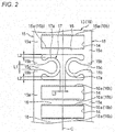
Fig. 2 is an enlarged top view illustrating a portion of a retainer. -
Fig. 3 is an axial sectional view of the retainer. -
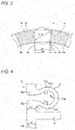
Fig. 4 is an enlarged top view illustrating main parts inFig. 2 . -
Fig. 5 is a view illustrating the radial deformation of an elastic deformable portion. -
Fig. 6A illustrates sectional views of the retainer and a shell which are not yet elastically deformed, andFig. 6B is a side view when the retainer and the shell are seen in a direction of arrow V inFig. 6A . -
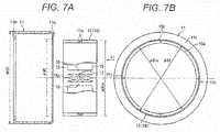
Fig. 7A illustrates sectional views of the retainer and the shell which are elastically deformed, andFig. 7B is a side view when the retainer and the shell are seen in a direction of arrow VI inFig. 7A . -
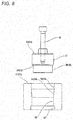
Fig. 8 is a view illustrating retainer insertion jigs. -
Fig. 9 shows views illustrating a state in which the shell outer ring and the retainer are respectively mounted on the retainer insertion jigs,Fig. 9A illustrates an example of when the retainer is mounted on a male jig, andFig. 9B illustrates an example of when the retainer is mounted on a female jig. -
Fig. 10 is a view illustrating a state in which the retainer is assembled with the shell outer ring using the retainer insertion jigs. -
Fig. 11 is an axial sectional view of another retainer. -
Fig. 12A is a view illustrating a retainer with which needles are assembled, andFig. 12B is a view illustrating a state in which the diameter of the retainer having the needles assembled therewith is reduced due to elastic deformation. -
Fig. 13 shows views illustrating a state in which the shell outer ring and the retainer having the needles assembled therewith are respectively mounted on the retainer insertion jigs,Fig. 13A illustrates an example of when the retainer having the needles assembled therewith is mounted on the male jig, andFig. 13B illustrates an example of when the retainer is mounted on the female jig. -
Fig. 14 is a view illustrating a state in which the retainer having the needles assembled therewith is assembled with the shell outer ring using the retainer insertion jigs. -
Fig. 15 is a sectional view illustrating a shell type needle roller bearing in the related art. - Hereinafter, a shell type needle roller bearing in an embodiment of the present invention will be described with reference to the accompanying drawings.
- As illustrated in
Fig. 1 , a shell typeneedle roller bearing 10 includes a shellouter ring 11 having an innercircumferential raceway surface 11a and a pair ofinward flange portions outer ring 11; a plurality ofneedles 12 that are disposed in the shellouter ring 11 in such a way as to be capable of rolling along theraceway surface 11a of the shellouter ring 11; and aretainer 13 having a plurality ofpockets 14 for retaining the plurality ofneedles 12. A shaft (or an inner ring member) (not illustrated) is rotatably supported by the shell typeneedle roller bearing 10. - The shell
outer ring 11 is manufactured by the plastic working (for example, deep drawing) of a cold rolled steel sheet (for example, which is made of low carbon steel such as SPCC) or the like such that the pair offlange portions outer ring 11 with a cylindrical shape in its entirety. The shellouter ring 11 is hardened by a heat treatment such as a carburizing treatment or a carbonitriding treatment. - Before the
needles 12 and theretainer 13 are assembled with the shellouter ring 11, theflange portions outer ring 11, and the shellouter ring 11 is hardened by a heat treatment. For this reason, unlike theflange 101c of the shellouter ring 101 in the related art, it is not necessary to set theflange portions flange portions outer ring 11 can be independent of orientation. The shellouter ring 11 can also be formed by cutting a thick steel sheet instead of the plastic working of a thin steel sheet. - As illustrated in
Fig. 2 , theretainer 13 includes a pair of coaxially disposedrim portions columnar portions 16 that connect the pair ofrim portions rim portions portions 15a. A plurality ofslits 15c are formed in therim portions slits 15c is formed betweenend portions portions 15a that are circumferentially adjacent to each other. A large number of theslits 15c decrease the number ofneedles 12, and thus, preferably, the number ofslits 15c is two to six. - A plurality of elastic
deformable portions 17 are circumferentially provided in theretainer 13 such that the retainer 13 (theslits 15c) is allowed to circumferentially contract, and each of the elasticdeformable portions 17 is provided in a region between thecolumnar portions slits 15c being formed in the region. - Each of the
pockets rim portions columnar portions deformable portion 17 being interposed therebetween. As illustrated inFig. 3 , radially inside lockingprotrusions retainer 13 and on both the circumferential side surfaces of thecolumnar portions columnar portions - The elastic
deformable portion 17 includes a pair of elasticdeformable pieces portions deformable pieces deformable portion 17 is formed symmetrical relative to an axial center portion C of theretainer 13. - As illustrated in an enlarged manner in
Fig. 4 , the elasticdeformable piece 17a is formed of a plurality of arcs 17a1, 17a2, and 17a3 which respectively have radii of curvature R1 to R3. The elasticdeformable piece 17a may be formed of a single arc. - When the strength of a base end portion is taken into consideration, an axial width w1 of the end portion (which is the base end portion of the elastic deformable portion 17) 15b of the arc-shaped
portion 15a is preferably greater than or equal to an axial width w2 of the arc-shapedportion 15a. An arc surface, which is formed on an axial inner surface of the base end portion, preferably has a large curvature (radius of curvature r is preferably small). - As illustrated in
Fig. 5 , a radial thickness h of the elasticdeformable piece 17a is set to be greater than a width w3 of the elasticdeformable piece 17a, and thus it is possible to restrict the elasticdeformable piece 17a from being radially deformed as illustrated by the arrow. - Hereinafter, a method (manufacturing method) of assembling the
retainer 13 with the aforementioned configuration into the shellouter ring 11 will be described. -
Fig. 6A illustrates sectional views of theretainer 13 and the shellouter ring 11 which are not yet elastically deformed, andFig. 6B is a side view when theretainer 13 and the shellouter ring 11 are seen in a direction of arrow V inFig. 6A .Fig. 7A illustrates sectional views of theretainer 13 and the shellouter ring 11 which are elastically deformed, andFig. 7B is a side view when theretainer 13 and the shellouter ring 11 are seen in a direction of arrow VI inFig. 7A . - An outer diameter φD1n of the
retainer 13 is greater than an inner diameter (hereinafter, which is referred to as a flange-portion inner diameter) φD2 of the pair ofinward flange portions Fig. 2 ) of each of theslits 15c is reduced by deforming the elasticdeformable portion 17, and as a result, the diameter of theretainer 13 can be circumferentially reduced. Accordingly, as illustrated inFig. 6 , the diameter of theretainer 13 can be reduced up to an outer diameter φD1s that is smaller than the flange-portion inner diameter φD2 of the shell outer ring 11 (φD2 > φD1s). A relationship between the sum of the outer circumferential length of theretainer 15 and the circumferential distances L1 of theslits 15c and the inner circumferential length of theinward flange portions outer ring 11 is substantially represented by an expression hereinbelow.
- The movable range of the elastic
deformable piece 17a, that is, the amount of deformation of the elasticdeformable piece 17a can be arbitrarily set by using an axial distance L3 (refer toFig. 3 ) between the pair of elasticdeformable pieces slit 15c. The circumferential distance L1 of theslit 15c which is not yet elastically deformed is set to be smaller than the sum of the circumferential distances L2, L2 between thecolumnar portions 16 and the elasticdeformable pieces 17a adjacent to each other in such a way that thecolumnar portion 16 is prevented from coming into contact with the elasticdeformable piece 17a before theslit 15c disappears (L1 < 2 x L2). - The outer diameter of the
retainer 13 is reduced until becoming smaller than the flange-portion inner diameter φD2 of the shellouter ring 11, and theretainer 13 is inserted into the shellouter ring 11. After the insertion, the elasticdeformable portions 17 are restored to the original state, and as a result, theretainer 13 is accommodated in the shellouter ring 11. - As illustrated in
Fig. 8 , retainer insertion jigs formed of afemale jig 21 and amale jig 26 are used to reduce the diameter of theretainer 13 and to insert theretainer 13 into the shellouter ring 11. - A shell outer ring-mounting stepped
portion 22, in which the shellouter ring 11 can be mounted, is provided at one axial end (lower end inFig. 8 ) of thefemale jig 21. The shell outer ring-mounting steppedportion 22 has a diameter slightly greater than an outer diameter φD3 of the shellouter ring 11, and is axially concave. A retainer-mounting steppedportion 25, in which theretainer 13 can be mounted, is provided at the other axial end (upper end inFig. 8 ) of thefemale jig 21. The retainer-mounting steppedportion 25 is coaxial with the shell outer ring-mounting steppedportion 22, has a diameter slightly greater than the outer diameter φD1n of theretainer 13, and is axially concave. A small-diameter hole 23 is provided on an inside end surface of the shell outer ring-mounting steppedportion 22. The small-diameter hole 23 is coaxial with the shell outer ring-mounting steppedportion 22, and has a diameter smaller than the flange-portion inner diameter φD2 of the shellouter ring 11. The small-diameter hole 23 is gradually connected to the retainer-mounting steppedportion 25 via a reduceddiameter hole 24 with a tapered shape, the diameter of which increases from the small-diameter hole 23 toward the retainer-mounting steppedportion 25. - The
male jig 26 includes acylindrical body portion 27, and a cylindricalretainer mounting portion 28 that is coaxial with thebody portion 27, and protrudes toward one end side (lower side inFig. 8 ) in the axial direction while being adjacent to thebody portion 27. Thebody portion 27 is set to have a diameter slightly smaller than the small-diameter hole 23 of thefemale jig 21, and thebody portion 27 can be inserted into the small-diameter hole 23. Theretainer mounting portion 28 is formed to have a diameter that is slightly smaller than a diameter obtained by subtracting two times the radial thickness h (refer toFig. 5 ) of theretainer 13 from the diameter of the small-diameter hole 23. A stepped portion between thebody portion 27 and theretainer mounting portion 28 serves as aretainer pressing portion 29 that is a flat surface perpendicular to the axial direction (flat surface perpendicular to the axis). Apressing shaft 20 is provided on thebody portion 27 side (the other end side in the axial direction and the upper side inFig. 8 ) of themale jig 26, with thebody portion 27 side being opposite to theretainer mounting portion 28. When themale jig 26 is inserted into thefemale jig 21, the pressingshaft 20 transmits an axial pressing force from a hand or a machine toward themale jig 26. The shape of thepressing shaft 20 may be selected so as to allow thepressing shaft 20 to be easily gripped by an operator, or to be easily attached to a machine, and thepressing shaft 20 does not necessarily have the shape illustrated inFig. 8 . - When the
retainer 13 is inserted into the shellouter ring 11, as illustrated inFigs 9A and 9B , the shellouter ring 11 is mounted in the shell outer ring-mounting steppedportion 22 of thefemale jig 21. As illustrated inFig. 9A , theretainer 13 is mounted in theretainer mounting portion 28 of themale jig 26, or as illustrated inFig. 9B , theretainer 13 is mounted in the retainer-mounting steppedportion 25 of thefemale jig 21. Themale jig 26 is inserted into thefemale jig 21 from the retainer-mounting steppedportion 25 side of thefemale jig 21. Theretainer 13 is axially pressed by theretainer pressing portion 29 of themale jig 26, and is pressed into thefemale jig 21 while the diameter of theretainer 13 is being reduced by the reduceddiameter hole 24 of thefemale jig 21. At this time, theretainer mounting portion 28 of themale jig 26 backs up theretainer 13 such that theretainer 13 is prevented from being abnormally deformed. As illustrated inFig. 10 , when theretainer 13 is inserted into the inside of the shell outer ring II, the diameter of theretainer 13 is restored to the original outer diameter φD1n, and theretainer 13 is prevented from falling off the shellouter ring 11. - The
needles pockets retainer 13 from the radial inside of theretainer 13. During the insertion operation, theneedles 12 are respectively pressed into thepockets columnar portions protrusions 16a are elastically deformed, with both circumferential sides of thepockets columnar portions protrusions 16a being respectively formed on the side surfaces of thecolumnar portions - A circumferential width Wp between portions of the
pocket 14 is greater than an outer diameter φDk of the needle 12 (Wp > φDk), in the portions deviating from the lockingprotrusions 16a, and thus theneedle 12 is allowed to roll in thepocket 14 by a small force while being retained in thepocket 14. A gap Wi, which is between free-state tip edges of the pair of radially inside lockingprotrusions pockets needle 12 φDk > Wi),. Accordingly, theneedles 12 retained in thepockets pockets - Hereinafter, another method of assembling the shell type needle roller bearing will be described. A
retainer 18 is only the difference among the configuration elements of the shell type needle roller bearing. Due to theretainer 18, a differentfemale jig 31 and a differentmale jig 36 are used. - As illustrated in
Fig. 3 , the radially inside lockingprotrusions retainer 13 over the entire length of thecolumnar portions columnar portions Fig. 11 , in addition to the radially inside lockingprotrusions protrusions retainer 18 which is used in this assembly method over the entire length of thecolumnar portions retainer 18 has the same configuration as theretainer 13 except that each portion has a different dimension, and a description will be given on the condition that the same reference signs are assigned to the same configuration elements. - First, the plurality of
needles pockets retainer 18. During the insertion operation, theneedles 12 are respectively pressed into thepockets columnar portions protrusions 16a or the radially outside lockingprotrusions 16b are elastically deformed, with both the circumferential sides of thepockets columnar portions protrusions 16a or the radially outside lockingprotrusions 16b being respectively formed on the side surfaces of thecolumnar portions pocket protrusions needle 12 is allowed to roll in thepocket 14 by a small force while being retained in thepocket 14. The gap Wi, which is between the free-state tip edges of the pair of radially inside lockingprotrusions pockets protrusions needles pockets pockets - As such, first, the plurality of
needles retainer 18, and thereafter, similar to theretainer 13, the diameter of theretainer 18 is reduced, and theretainer 18 is assembled with the shellouter ring 11. For this reason, a subassembly obtained by assembling the plurality ofneedles retainer 18 is handled as a unit, and thus it is possible to increase the degree of freedom in the assembly step. - As illustrated in
Figs. 6 and7 , the outer diameter φD1n of theretainer 18 is greater than the flange-portion inner diameter φD2 of the shellouter ring 11. As illustrated inFig. 12 , a circumferential distance L4 of each of theslit 15c is reduced by deforming the elasticdeformable portion 17, and as a result, the diameter of theretainer 18 can be circumferentially reduced.Fig. 12A is a view illustrating theretainer 18 with which the plurality ofneedles Fig. 12B is a view illustrating a state in which the diameter of theretainer 18 having the plurality ofneedles retainer 18 having the plurality ofneedles outer ring 11. - The maximum outer diameter of the
retainer 18 having the plurality ofneedles outer ring 11, and theretainer 18 is inserted into the shellouter ring 11. After the insertion, the elasticdeformable portions 17 is restored to the original state, and as a result, theretainer 18 is accommodated in the shellouter ring 11. - As illustrated in
Fig. 8 , retainer insertion jigs formed of thefemale jig 31 and themale jig 36 are used to reduce the diameter of theretainer 18 having the plurality ofneedles retainer 18 into the shellouter ring 11. As illustrated inFig. 8 , thefemale jig 21 is the same as thefemale jig 31, and themale jig 26 is the same as themale jig 36 except that each portion has a different dimension, and a description will be given on the condition that the same reference signs are assigned to the same configuration elements. - The shell outer ring-mounting stepped
portion 22, in which the shellouter ring 11 can be mounted, is provided at one axial end (lower end inFig. 8 ) of thefemale jig 31. The shell outer ring-mounting steppedportion 22 has a diameter slightly greater than the outer diameter φD3 of the shellouter ring 11, and is axially concave. A retainer-mounting steppedportion 35 is provided at the other axial end (upper end inFig. 8 ) of thefemale jig 31. The retainer-mounting steppedportion 35 is coaxial with the shell outer ring-mounting steppedportion 22, and is axially concave. The diameter of the retainer-mounting steppedportion 35 is slightly greater than the maximum outer diameter φD4n (refer toFig. 12A ) of theretainer 18 with which the plurality ofneedles retainer 13 with which the plurality ofneedles diameter hole 23 is provided on the inside end surface of the shell outer ring-mounting steppedportion 22. The small-diameter hole 23 is coaxial with the shell outer ring-mounting steppedportion 22, and has a diameter smaller than the flange-portion inner diameter φD2 of the shellouter ring 11. The small-diameter hole 23 is gradually connected to the retainer-mounting steppedportion 35 via a reduceddiameter hole 34 with a tapered shape, the diameter of which increases from the small-diameter hole 23 toward the retainer-mounting steppedportion 35. - The
male jig 36 includes thecylindrical body portion 27, and aretainer mounting portion 38 that is coaxial with thebody portion 27, and protrudes toward one end side (lower side inFig. 8 ) in the axial direction while being adjacent to thebody portion 27. Thebody portion 27 is set to have a diameter slightly smaller than the small-diameter hole 23 of thefemale jig 31, and thebody portion 27 can be inserted into the small-diameter hole 23. Theretainer mounting portion 38 is formed to have a diameter that is slightly smaller than a diameter obtained by subtracting two times the outer diameter φDk (refer toFig. 11 ) of theneedle 12 from the diameter of the small-diameter hole 23. A stepped portion between thebody portion 27 and theretainer mounting portion 38 serves as aretainer pressing portion 39 that is a flat surface perpendicular to the axial direction (flat surface perpendicular to the axis). Thepressing shaft 20 is provided on thebody portion 27 side (the other end side in the axial direction and the upper side inFig. 8 ) of themale jig 36, with thebody portion 27 side being opposite to theretainer mounting portion 38. When themale jig 36 is inserted into thefemale jig 31, the pressingshaft 20 transmits an axial pressing force from a hand or a machine toward themale jig 36. The shape of thepressing shaft 20 may be selected so as to allow thepressing shaft 20 to be easily gripped by an operator, or to be easily attached to a machine, and thepressing shaft 20 does not necessarily have the shape illustrated inFig. 8 . - When the
retainer 18 is inserted into the shellouter ring 11, as illustrated inFigs 13A and 13B , the shellouter ring 11 is mounted in the shell outer ring-mounting steppedportion 22 of thefemale jig 31. Theretainer 18 having the plurality ofneedles portion 35 of themale jig 26, or is mounted in theretainer mounting portion 38 of themale jig 36. Themale jig 36 is inserted into thefemale jig 31 from the retainer-mounting steppedportion 35 side of thefemale jig 31. Theretainer 18 is axially pressed by theretainer pressing portion 39 of themale jig 36, and is pressed into thefemale jig 31 while the diameter of theretainer 18 is being reduced by the reduceddiameter hole 34 of thefemale jig 31. At this time, theretainer mounting portion 38 of themale jig 36 backs up theretainer 18 such that theretainer 18 is prevented from being abnormally deformed. As illustrated inFig. 14 , when theretainer 18 is inserted into the inside of the shellouter ring 11, the diameter of theretainer 18 is restored to the original outer diameter φD1n, and theretainer 8 is prevented from falling off the shellouter ring 11. - The
retainers retainers 13 and 18: polyamide (nylon resin) such as aromatic polyamide (aromatic PA), polyamide 46,polyamide 6, polyamide 66; fluororesin such as polyphenylene sulfide (PPS), polyetheretherketone (PEEK), polyacetal (POM), polytetrafluoroethylene (PTFE); and the like. Perferably, it is possible to use any one of the aforementioned resin in which a reinforcement such as glass fiber or carbon fiber is mixed. More preferably, 5% by weight to 30% by weight of glass fiber or carbon fiber may be mixed in the polyamide resin, and thus bending elastic modulus may be set to 2000 MPa to 5000 MPa. When the bending elastic modulus is within this range, more preferably, the deformable portion is capable of having deformability and necessary rigidity. - In the embodiment, the radially inside locking
protrusion 16a and the radially outside lockingprotrusion 16b are formed over the entire length of each of thecolumnar portions protrusion 16a and the radially outside lockingprotrusion 16b may be provided only in a range shorter than the entire length, or may be provided while being divided into a plurality of pieces. - As described above, in the shell type
needle roller bearing 10 in the embodiment, the plurality of elasticdeformable portions 17 are circumferentially provided in each of theretainers retainers deformable portion 17 is formed symmetrical relative to the axial center portion C. Therefore, it is possible to provide theretainers needle 12 is appropriately allowed, and the fretting of theneedle 12 can be prevented by the elasticdeformable portion 17. - Each of the pair of
rim portions portions 15a. The plurality ofslits 15c are formed in the pair ofrim portions slits 15c is formed between theend portions 15b of the arc-shapedportions 15a that are circumferentially adjacent to each other. The elasticdeformable portion 17 includes the pair of elasticdeformable pieces end portions 15b of the arc-shapedportions 15a circumferentially adjacent to each other, and the extended portions of which are connected together in the circumferential direction. Accordingly, it is possible to form the elasticdeformable portion 17 that is symmetrical relative to the axial center portion C. - The elastic
deformable portion 17 is formed between thecolumnar portions slit 15c is smaller than the sum of the circumferential distances L2 between thecolumnar portions 16 and the elasticdeformable pieces 17a adjacent to each other. Therefore, it is possible to ensure a sufficient amount of deformation without thecolumnar portion 16 coming into contact with the elasticdeformable piece 17a before theslit 15c disappears when the elasticdeformable portion 17 circumferentially contract. - Since either the
retainer 13 or theretainer 18, and theneedles 12 are assembled with the shellouter ring 11 after both theflange portions outer ring 11 are formed, and a heat treatment is applied to the shellouter ring 11, the plating step in the related art is not required, and the retainer is not thermally affected by the heat treatment. Therefore, resin can be used as the material of theretainers - The present invention is not limited to the aforementioned embodiment, and modifications, improvements, or the like can be appropriately made to the embodiment.
- This application is on the basis of
Japanese Patent Application No. 2013- 174526 - As described above, according to the method of manufacturing a shell type needle roller bearing and the assembly jigs of the present invention, after both the flange portions of the shell outer ring are formed and a heat treatment is applied to the shell outer ring, the retainer and the needles are assembled with the shell outer ring, and thus a plating step, which has been required in the related art, is not required, and the retainer is not thermally affected by the heat treatment. Therefore, resin can be used as the material of the retainer, and this manufacturing method can be preferably adopted as a method of manufacturing a shell type needle roller bearing used in rotation support portions of various pieces of machinery.
- 10: SHELL TYPE NEEDLE ROLLER BEARING, 11: SHELL OUTER RING, 11a: RACEWAY SURFACE, 11b: FLANGE PORTION, 11c: FLANGE PORTION, 12: NEEDLE, 13: RETAINER, 14: POCKET, 15: RIM PORTION, 15a: ARC-SHAPED PORTION, 15b: END PORTION, 15c: SLIT, 16: COLUMNAR PORTION, 16a: RADIALLY OUTSIDE LOCKING PROTRUSION, 16b: RADIALLY INSIDE LOCKING PROTRUSION, 17: ELASTIC DEFORMABLE PORTION, 17a: ELASTIC DEFORMABLE PIECE, 17a1: ARC, 17a2: ARC, 17a3: ARC, 18: RETAINER, 20: PRESSING SHAFT, 21: FEMALE JIG, 22: SHELL OUTER RING-MOUNTING STEPPED PORTION, 23: SMALL-DIAMETER PORTION, 24: REDUCED DIAMETER HOLE, 25: RETAINER-MOUNTING STEPPED PORTION, 26: MALE JIG, 27: BODY PORTION, 28: RETAINER MOUNTING PORTION, 29: RETAINER PRESSING PORTION, 31: FEMALE JIG, 34: REDUCED DIAMETER HOLE, 35: RETAINER-MOUNTING STEPPED PORTION, 36: MALE JIG, 38: RETAINER MOUNTING PORTION, 39: RETAINER PRESSING PORTION, 100: SHELL TYPE NEEDLE ROLLER BEARING, 101: SHELL OUTER RING, 101a: RACEWAY SURFACE, 101b: FLANGE PORTION, 101c: FLANGE PORTION, 102: NEEDLE, 103: RETAINER
Claims (4)
- A method of manufacturing a shell type needle roller bearing including a shell outer ring having an inner circumferential raceway surface and a pair of inward flange portions in both end portions of the shell outer ring; a plurality of needles that are disposed in the shell outer ring in such a way as to be capable of rolling along the raceway surface of the shell outer ring; and a retainer having a plurality of pockets for retaining the plurality of needles,
wherein the diameter of the retainer can be reduced,
wherein after both the flange portions of the shell outer ring are formed and a heat treatment is applied to the shell outer ring, the diameter of the retainer having the plurality of needles assembled therewith is reduced to a diameter smaller than a flange-portion inner diameter of the shell outer ring and the retainer is inserted into the shell outer ring using a retainer insertion jig,
wherein the retainer insertion jig is formed of a female jig and a malejig, wherein a shell outer ring-mounting stepped portion, in which the shell outer ring can be mounted, is provided at one axial end of the female jig, has a diameter greater than the outer diameter of the shell outer ring, and is axially concave,
wherein a retainer-mounting stepped portion, in which the retainer can be mounted while being assembled with the plurality of needles, is provided at the other axial end of the female jig, is coaxial with the shell outer ring-mounting stepped portion, has a diameter greater than the maximum outer diameter of the retainer with which the plurality of needles are assembled, and is axially concave,
wherein a small-diameter hole is provided on an inside end surface of the shell outer ring-mounting stepped portion, is coaxial with the shell outer ring-mounting stepped portion, and has a diameter smaller than the flange-portion inner diameter of the shell outer ring,
wherein the small-diameter hole is gradually connected to the retainer-mounting stepped portion via a reduced diameter hole with a tapered shape, the diameter of which increases from the small-diameter hole toward the retainer-mounting stepped portion,
wherein the male jig includes a body portion which has a diameter smaller than that of the small-diameter hole of the female jig such that the body portion can be inserted into the small-diameter hole, and a retainer mounting portion that is coaxial with the body portion, protrudes in an axial direction while being adjacent to the body portion, and has a diameter that is smaller than a diameter obtained by subtracting two times the outer diameter of the needle from the diameter of the small-diameter hole,
wherein a stepped portion between the body portion and the retainer mounting portion serves as a retainer pressing portion that is a flat surface perpendicular to the axis, and
wherein when the retainer is inserted into the shell outer ring,
the shell outer ring is mounted in the shell outer ring-mounting stepped portion of the female jig,
the retainer having the plurality of needles assembled therewith is mounted in the retainer mounting portion of the male jig, or in the retainer-mounting stepped portion of the female jig, and
the male jig is inserted into the female jig from the retainer-mounting stepped portion side of the female jig, and thus the retainer having the plurality of needles assembled therewith is inserted into the shell outer ring. - A method of manufacturing a shell type needle roller bearing including a shell outer ring having an inner circumferential raceway surface and a pair of inward flange portions in both end portions of the shell outer ring; a plurality of needles that are disposed in the shell outer ring in such a way as to be capable of rolling along the raceway surface of the shell outer ring; and a retainer having a plurality of pockets for retaining the plurality of needles,
wherein the diameter of the retainer can be reduced,
wherein after both the flange portions of the shell outer ring are formed and a heat treatment is applied to the shell outer ring, the diameter of the retainer is reduced to a diameter smaller than a flange-portion inner diameter of the shell outer ring, the retainer is inserted into the shell outer ring using a retainer insertion jig, and then the plurality of needles are respectively inserted into the pockets of the retainer,
wherein the retainer insertion jig is formed of a female jig and a male jig, wherein a shell outer ring-mounting stepped portion, in which the shell outer ring can be mounted, is provided at one axial end of the female jig, has a diameter greater than the outer diameter of the shell outer ring, and is axially concave,
wherein a retainer-mounting stepped portion, in which the retainer can be mounted, is provided at the other axial end of the female jig, is coaxial with the shell outer ring-mounting stepped portion, has a diameter greater than the outer diameter of the retainer, and is axially concave,
wherein a small-diameter hole is provided on an inside end surface of the shell outer ring-mounting stepped portion, is coaxial with the shell outer ring-mounting stepped portion, and has a diameter smaller than the flange-portion inner diameter of the shell outer ring,
wherein the small-diameter hole is gradually connected to the retainer-mounting stepped portion via a reduced diameter hole with a tapered shape, the diameter of which increases from the small-diameter hole toward the retainer-mounting stepped portion,
wherein the male jig includes a body portion which has a diameter smaller than that of the small-diameter hole of the female jig such that the body portion can be inserted into the small-diameter hole, and a retainer mounting portion that is coaxial with the body portion, protrudes in an axial direction while being adjacent to the body portion, and has a diameter that is smaller than a diameter obtained by subtracting two times the radial thickness of the retainer from the diameter of the small-diameter hole,
wherein a stepped portion between the body portion and the retainer mounting portion serves as a retainer pressing portion that is a flat surface perpendicular to the axis, and
wherein when the retainer is inserted into the shell outer ring,
the shell outer ring is mounted in the shell outer ring-mounting stepped portion of the female jig,
the retainer is mounted in the retainer mounting portion of the male jig, or in the retainer-mounting stepped portion of the female jig, and
the male jig is inserted into the female jig from the retainer-mounting stepped portion side of the female jig, and thus the retainer is inserted into the shell outer ring. - A manufacturing jig used to manufacture a shell type needle roller bearing including a shell outer ring having an inner circumferential raceway surface and a pair of inward flange portions in both end portions of the shell outer ring; a plurality of needles that are disposed in the shell outer ring in such a way as to be capable of rolling along the raceway surface of the shell outer ring; and a retainer having a plurality of pockets for retaining the plurality of needles,
wherein the manufacturing jig is formed of a female jig and a male jig,
wherein a shell outer ring-mounting stepped portion, in which the shell outer ring can be mounted, is provided at one axial end of the female jig, has a diameter greater than the outer diameter of the shell outer ring, and is axially concave,
wherein a retainer-mounting stepped portion, in which the retainer can be mounted while being assembled with the plurality of needles, is provided at the other axial end of the female jig, is coaxial with the shell outer ring-mounting stepped portion, has a diameter greater than the maximum outer diameter of the retainer with which the plurality of needles are assembled, and is axially concave,
wherein a small-diameter hole is provided on an inside end surface of the shell outer ring-mounting stepped portion, is coaxial with the shell outer ring-mounting stepped portion, and has a diameter smaller than a flange-portion inner diameter of the shell outer ring,
wherein the small-diameter hole is gradually connected to the retainer-mounting stepped portion via a reduced diameter hole with a tapered shape, the diameter of which increases from the small-diameter hole toward the retainer-mounting stepped portion,
wherein the male jig includes a body portion which has a diameter smaller than that of the small-diameter hole of the female jig such that the body portion can be inserted into the small-diameter hole, and a retainer mounting portion that is coaxial with the body portion, protrudes in an axial direction while being adjacent to the body portion, and has a diameter that is smaller than a diameter obtained by subtracting two times the outer diameter of the needle from the diameter of the small-diameter hole, and
wherein a stepped portion between the body portion and the retainer mounting portion serves as a retainer pressing portion that is a flat surface perpendicular to the axis. - A manufacturing jig used to manufacture a shell type needle roller bearing including a shell outer ring having an inner circumferential raceway surface and a pair of inward flange portions in both end portions of the shell outer ring; a plurality of needles that are disposed in the shell outer ring in such a way as to be capable of rolling along the raceway surface of the shell outer ring; and a retainer having a plurality of pockets for retaining the plurality of needles,
wherein the manufacturing jig is formed of a female jig and a male jig, wherein a shell outer ring-mounting stepped portion, in which the shell outer ring can be mounted, is provided at one axial end of the female jig, has a diameter greater than the outer diameter of the shell outer ring, and is axially concave,
wherein a retainer-mounting stepped portion, in which the retainer can be mounted, is provided at the other axial end of the female jig, is coaxial with the shell outer ring-mounting stepped portion, has a diameter greater than the outer diameter of the retainer, and is axially concave,
wherein a small-diameter hole is provided on an inside end surface of the shell outer ring-mounting stepped portion, is coaxial with the shell outer ring-mounting stepped portion, and has a diameter smaller than a flange-portion inner diameter of the shell outer ring,
wherein the small-diameter hole is gradually connected to the retainer-mounting stepped portion via a reduced diameter hole with a tapered shape, the diameter of which increases from the small-diameter hole toward the retainer-mounting stepped portion,
wherein the male jig includes a body portion which has a diameter smaller than that of the small-diameter hole of the female jig such that the body portion can be inserted into the small-diameter hole, and a retainer mounting portion that is coaxial with the body portion, protrudes in an axial direction while being adjacent to the body portion, and has a diameter that is smaller than a diameter obtained by subtracting two times the radial thickness of the retainer from the diameter of the small-diameter hole, and
wherein a stepped portion between the body portion and the retainer mounting portion serves as a retainer pressing portion that is a flat surface perpendicular to the axis.
Applications Claiming Priority (2)
| Application Number | Priority Date | Filing Date | Title |
|---|---|---|---|
| JP2013174526 | 2013-08-26 | ||
| PCT/JP2013/083464 WO2015029271A1 (en) | 2013-08-26 | 2013-12-13 | Method for manufacturing shell-type needle bearing, and manufacturing jig used in manufacture of same |
Publications (3)
| Publication Number | Publication Date |
|---|---|
| EP3040569A1 true EP3040569A1 (en) | 2016-07-06 |
| EP3040569A4 EP3040569A4 (en) | 2016-08-24 |
| EP3040569B1 EP3040569B1 (en) | 2019-07-17 |
Family
ID=52585873
Family Applications (1)
| Application Number | Title | Priority Date | Filing Date |
|---|---|---|---|
| EP13892274.5A Not-in-force EP3040569B1 (en) | 2013-08-26 | 2013-12-13 | Method for manufacturing shell-type needle bearing, and manufacturing jig used in manufacture of same |
Country Status (6)
| Country | Link |
|---|---|
| US (1) | US9689429B2 (en) |
| EP (1) | EP3040569B1 (en) |
| JP (1) | JP6041055B2 (en) |
| KR (1) | KR101827184B1 (en) |
| CN (1) | CN105492789B (en) |
| WO (1) | WO2015029271A1 (en) |
Cited By (1)
| Publication number | Priority date | Publication date | Assignee | Title |
|---|---|---|---|---|
| WO2024081207A1 (en) * | 2022-10-11 | 2024-04-18 | Koyo Bearings North America Llc | Radial bearing assembly having spring rim retainer |
Families Citing this family (3)
| Publication number | Priority date | Publication date | Assignee | Title |
|---|---|---|---|---|
| CN106050908B (en) * | 2016-08-12 | 2018-04-13 | 安徽江淮汽车集团股份有限公司 | A kind of needle roller bushing and its auxiliary assembling structure |
| JP7079050B2 (en) * | 2017-02-22 | 2022-06-01 | 株式会社ジェイテクト | Cage for thrust roller bearings and thrust roller bearings |
| JP7537467B2 (en) * | 2022-04-26 | 2024-08-21 | トヨタ自動車株式会社 | Ring mounting tool and ring mounting method |
Family Cites Families (14)
| Publication number | Priority date | Publication date | Assignee | Title |
|---|---|---|---|---|
| US2368175A (en) * | 1942-06-11 | 1945-01-30 | Torrington Co | Needle roller construction |
| US3054164A (en) * | 1960-04-06 | 1962-09-18 | Schatz Mfg Company | Method of producing and assembling antifriction bearings |
| US5848846A (en) * | 1996-07-26 | 1998-12-15 | Ntn Corporation | Shell type needle roller bearing and method of producing the same |
| JPH11303863A (en) | 1998-04-15 | 1999-11-02 | Nippon Seiko Kk | Shell type roller bearing |
| JP2002139067A (en) | 2000-11-06 | 2002-05-17 | Nsk Ltd | Manufacturing method of shell type needle roller bearing |
| DE10119889B4 (en) * | 2001-04-24 | 2004-02-19 | Aktiebolaget Skf | roller bearing |
| JP4211397B2 (en) * | 2003-01-06 | 2009-01-21 | 株式会社ジェイテクト | Roller bearing |
| JP2005163904A (en) | 2003-12-02 | 2005-06-23 | Ntn Corp | Clutch |
| JP2005163994A (en) | 2003-12-05 | 2005-06-23 | Koyo Seiko Co Ltd | Retainer for roller bearing and roller bearing |
| JP2005233322A (en) * | 2004-02-20 | 2005-09-02 | Ntn Corp | Roller bearing and assembling method thereof |
| JP2006057707A (en) * | 2004-08-19 | 2006-03-02 | Ntn Corp | Roller bearing with outer ring |
| JP2006144839A (en) * | 2004-11-17 | 2006-06-08 | Ntn Corp | Roller bearing |
| WO2011078359A1 (en) * | 2009-12-25 | 2011-06-30 | 日本精工株式会社 | Needle bearing |
| JP5732830B2 (en) * | 2010-11-30 | 2015-06-10 | 日本精工株式会社 | Needle bearing |
-
2013
- 2013-12-13 JP JP2015533932A patent/JP6041055B2/en not_active Expired - Fee Related
- 2013-12-13 KR KR1020167004532A patent/KR101827184B1/en not_active Expired - Fee Related
- 2013-12-13 US US14/913,874 patent/US9689429B2/en not_active Expired - Fee Related
- 2013-12-13 CN CN201380079132.1A patent/CN105492789B/en not_active Expired - Fee Related
- 2013-12-13 EP EP13892274.5A patent/EP3040569B1/en not_active Not-in-force
- 2013-12-13 WO PCT/JP2013/083464 patent/WO2015029271A1/en not_active Ceased
Cited By (1)
| Publication number | Priority date | Publication date | Assignee | Title |
|---|---|---|---|---|
| WO2024081207A1 (en) * | 2022-10-11 | 2024-04-18 | Koyo Bearings North America Llc | Radial bearing assembly having spring rim retainer |
Also Published As
| Publication number | Publication date |
|---|---|
| JPWO2015029271A1 (en) | 2017-03-02 |
| US9689429B2 (en) | 2017-06-27 |
| JP6041055B2 (en) | 2016-12-07 |
| CN105492789B (en) | 2018-02-27 |
| US20160208855A1 (en) | 2016-07-21 |
| WO2015029271A1 (en) | 2015-03-05 |
| KR101827184B1 (en) | 2018-02-07 |
| EP3040569B1 (en) | 2019-07-17 |
| KR20160033222A (en) | 2016-03-25 |
| EP3040569A4 (en) | 2016-08-24 |
| CN105492789A (en) | 2016-04-13 |
Similar Documents
| Publication | Publication Date | Title |
|---|---|---|
| JP5776547B2 (en) | Needle bearing | |
| US20110091144A1 (en) | Roller bearing cage, roller bearing, and method for producing roller bearing cage | |
| US7896557B2 (en) | Needle roller bearing | |
| EP3040569B1 (en) | Method for manufacturing shell-type needle bearing, and manufacturing jig used in manufacture of same | |
| JP2007537415A (en) | Helical gear assembly | |
| US7934872B2 (en) | Drawn cup roller bearing and method of producing drawn cup roller bearing | |
| US9644677B2 (en) | Preliminary retainer for radial needle bearing | |
| EP3001050A1 (en) | Rolling bearing | |
| JP2001208054A (en) | Tapered roller bearing | |
| US9709088B2 (en) | Method for manufacturing a radial and axial combination bearing and resulting bearing | |
| KR20180051391A (en) | Sealing structure | |
| JP7472544B2 (en) | Cylindrical roller bearing with outer ring | |
| JP2012202456A (en) | Pin type retainer, rolling device, and roller bearing | |
| CN109844338B (en) | Bearing assemblies and bearing housings | |
| US10670075B2 (en) | Thrust roller bearing | |
| JP6750331B2 (en) | Method for manufacturing cage for thrust roller bearing | |
| JP2005172037A (en) | Roller bearing | |
| JP4928331B2 (en) | Shell outer ring manufacturing method and shell needle roller bearing | |
| US20250012324A1 (en) | Rolling bearing | |
| JP2016029286A (en) | Method for assembling shell type needle bearing | |
| JP2005106252A (en) | Roller bearing |
Legal Events
| Date | Code | Title | Description |
|---|---|---|---|
| PUAI | Public reference made under article 153(3) epc to a published international application that has entered the european phase |
Free format text: ORIGINAL CODE: 0009012 |
|
| 17P | Request for examination filed |
Effective date: 20160204 |
|
| AK | Designated contracting states |
Kind code of ref document: A1 Designated state(s): AL AT BE BG CH CY CZ DE DK EE ES FI FR GB GR HR HU IE IS IT LI LT LU LV MC MK MT NL NO PL PT RO RS SE SI SK SM TR |
|
| AX | Request for extension of the european patent |
Extension state: BA ME |
|
| A4 | Supplementary search report drawn up and despatched |
Effective date: 20160722 |
|
| RIC1 | Information provided on ipc code assigned before grant |
Ipc: F16C 43/04 20060101AFI20160718BHEP Ipc: F16C 33/46 20060101ALI20160718BHEP Ipc: F16C 33/48 20060101ALI20160718BHEP Ipc: F16C 19/24 20060101ALI20160718BHEP Ipc: F16C 43/06 20060101ALI20160718BHEP Ipc: F16C 19/44 20060101ALI20160718BHEP |
|
| DAX | Request for extension of the european patent (deleted) | ||
| STAA | Information on the status of an ep patent application or granted ep patent |
Free format text: STATUS: REQUEST FOR EXAMINATION WAS MADE |
|
| R17P | Request for examination filed (corrected) |
Effective date: 20160204 |
|
| RIC1 | Information provided on ipc code assigned before grant |
Ipc: F16C 43/06 20060101ALI20181213BHEP Ipc: F16C 43/04 20060101AFI20181213BHEP Ipc: F16C 19/24 20060101ALI20181213BHEP Ipc: F16C 33/46 20060101ALI20181213BHEP Ipc: F16C 33/48 20060101ALI20181213BHEP Ipc: F16C 19/44 20060101ALI20181213BHEP |
|
| GRAP | Despatch of communication of intention to grant a patent |
Free format text: ORIGINAL CODE: EPIDOSNIGR1 |
|
| STAA | Information on the status of an ep patent application or granted ep patent |
Free format text: STATUS: GRANT OF PATENT IS INTENDED |
|
| INTG | Intention to grant announced |
Effective date: 20190213 |
|
| GRAS | Grant fee paid |
Free format text: ORIGINAL CODE: EPIDOSNIGR3 |
|
| GRAA | (expected) grant |
Free format text: ORIGINAL CODE: 0009210 |
|
| STAA | Information on the status of an ep patent application or granted ep patent |
Free format text: STATUS: THE PATENT HAS BEEN GRANTED |
|
| AK | Designated contracting states |
Kind code of ref document: B1 Designated state(s): AL AT BE BG CH CY CZ DE DK EE ES FI FR GB GR HR HU IE IS IT LI LT LU LV MC MK MT NL NO PL PT RO RS SE SI SK SM TR |
|
| REG | Reference to a national code |
Ref country code: GB Ref legal event code: FG4D |
|
| REG | Reference to a national code |
Ref country code: CH Ref legal event code: EP |
|
| REG | Reference to a national code |
Ref country code: IE Ref legal event code: FG4D |
|
| REG | Reference to a national code |
Ref country code: DE Ref legal event code: R096 Ref document number: 602013058053 Country of ref document: DE |
|
| REG | Reference to a national code |
Ref country code: AT Ref legal event code: REF Ref document number: 1156122 Country of ref document: AT Kind code of ref document: T Effective date: 20190815 |
|
| REG | Reference to a national code |
Ref country code: NL Ref legal event code: MP Effective date: 20190717 |
|
| REG | Reference to a national code |
Ref country code: LT Ref legal event code: MG4D |
|
| REG | Reference to a national code |
Ref country code: AT Ref legal event code: MK05 Ref document number: 1156122 Country of ref document: AT Kind code of ref document: T Effective date: 20190717 |
|
| PG25 | Lapsed in a contracting state [announced via postgrant information from national office to epo] |
Ref country code: HR Free format text: LAPSE BECAUSE OF FAILURE TO SUBMIT A TRANSLATION OF THE DESCRIPTION OR TO PAY THE FEE WITHIN THE PRESCRIBED TIME-LIMIT Effective date: 20190717 Ref country code: AT Free format text: LAPSE BECAUSE OF FAILURE TO SUBMIT A TRANSLATION OF THE DESCRIPTION OR TO PAY THE FEE WITHIN THE PRESCRIBED TIME-LIMIT Effective date: 20190717 Ref country code: NL Free format text: LAPSE BECAUSE OF FAILURE TO SUBMIT A TRANSLATION OF THE DESCRIPTION OR TO PAY THE FEE WITHIN THE PRESCRIBED TIME-LIMIT Effective date: 20190717 Ref country code: BG Free format text: LAPSE BECAUSE OF FAILURE TO SUBMIT A TRANSLATION OF THE DESCRIPTION OR TO PAY THE FEE WITHIN THE PRESCRIBED TIME-LIMIT Effective date: 20191017 Ref country code: PT Free format text: LAPSE BECAUSE OF FAILURE TO SUBMIT A TRANSLATION OF THE DESCRIPTION OR TO PAY THE FEE WITHIN THE PRESCRIBED TIME-LIMIT Effective date: 20191118 Ref country code: LT Free format text: LAPSE BECAUSE OF FAILURE TO SUBMIT A TRANSLATION OF THE DESCRIPTION OR TO PAY THE FEE WITHIN THE PRESCRIBED TIME-LIMIT Effective date: 20190717 Ref country code: SE Free format text: LAPSE BECAUSE OF FAILURE TO SUBMIT A TRANSLATION OF THE DESCRIPTION OR TO PAY THE FEE WITHIN THE PRESCRIBED TIME-LIMIT Effective date: 20190717 Ref country code: NO Free format text: LAPSE BECAUSE OF FAILURE TO SUBMIT A TRANSLATION OF THE DESCRIPTION OR TO PAY THE FEE WITHIN THE PRESCRIBED TIME-LIMIT Effective date: 20191017 Ref country code: FI Free format text: LAPSE BECAUSE OF FAILURE TO SUBMIT A TRANSLATION OF THE DESCRIPTION OR TO PAY THE FEE WITHIN THE PRESCRIBED TIME-LIMIT Effective date: 20190717 |
|
| PGFP | Annual fee paid to national office [announced via postgrant information from national office to epo] |
Ref country code: DE Payment date: 20191203 Year of fee payment: 7 |
|
| PG25 | Lapsed in a contracting state [announced via postgrant information from national office to epo] |
Ref country code: IS Free format text: LAPSE BECAUSE OF FAILURE TO SUBMIT A TRANSLATION OF THE DESCRIPTION OR TO PAY THE FEE WITHIN THE PRESCRIBED TIME-LIMIT Effective date: 20191117 Ref country code: RS Free format text: LAPSE BECAUSE OF FAILURE TO SUBMIT A TRANSLATION OF THE DESCRIPTION OR TO PAY THE FEE WITHIN THE PRESCRIBED TIME-LIMIT Effective date: 20190717 Ref country code: AL Free format text: LAPSE BECAUSE OF FAILURE TO SUBMIT A TRANSLATION OF THE DESCRIPTION OR TO PAY THE FEE WITHIN THE PRESCRIBED TIME-LIMIT Effective date: 20190717 Ref country code: ES Free format text: LAPSE BECAUSE OF FAILURE TO SUBMIT A TRANSLATION OF THE DESCRIPTION OR TO PAY THE FEE WITHIN THE PRESCRIBED TIME-LIMIT Effective date: 20190717 Ref country code: GR Free format text: LAPSE BECAUSE OF FAILURE TO SUBMIT A TRANSLATION OF THE DESCRIPTION OR TO PAY THE FEE WITHIN THE PRESCRIBED TIME-LIMIT Effective date: 20191018 Ref country code: LV Free format text: LAPSE BECAUSE OF FAILURE TO SUBMIT A TRANSLATION OF THE DESCRIPTION OR TO PAY THE FEE WITHIN THE PRESCRIBED TIME-LIMIT Effective date: 20190717 |
|
| PG25 | Lapsed in a contracting state [announced via postgrant information from national office to epo] |
Ref country code: TR Free format text: LAPSE BECAUSE OF FAILURE TO SUBMIT A TRANSLATION OF THE DESCRIPTION OR TO PAY THE FEE WITHIN THE PRESCRIBED TIME-LIMIT Effective date: 20190717 |
|
| PG25 | Lapsed in a contracting state [announced via postgrant information from national office to epo] |
Ref country code: DK Free format text: LAPSE BECAUSE OF FAILURE TO SUBMIT A TRANSLATION OF THE DESCRIPTION OR TO PAY THE FEE WITHIN THE PRESCRIBED TIME-LIMIT Effective date: 20190717 Ref country code: EE Free format text: LAPSE BECAUSE OF FAILURE TO SUBMIT A TRANSLATION OF THE DESCRIPTION OR TO PAY THE FEE WITHIN THE PRESCRIBED TIME-LIMIT Effective date: 20190717 Ref country code: IT Free format text: LAPSE BECAUSE OF FAILURE TO SUBMIT A TRANSLATION OF THE DESCRIPTION OR TO PAY THE FEE WITHIN THE PRESCRIBED TIME-LIMIT Effective date: 20190717 Ref country code: RO Free format text: LAPSE BECAUSE OF FAILURE TO SUBMIT A TRANSLATION OF THE DESCRIPTION OR TO PAY THE FEE WITHIN THE PRESCRIBED TIME-LIMIT Effective date: 20190717 Ref country code: PL Free format text: LAPSE BECAUSE OF FAILURE TO SUBMIT A TRANSLATION OF THE DESCRIPTION OR TO PAY THE FEE WITHIN THE PRESCRIBED TIME-LIMIT Effective date: 20190717 |
|
| PG25 | Lapsed in a contracting state [announced via postgrant information from national office to epo] |
Ref country code: IS Free format text: LAPSE BECAUSE OF FAILURE TO SUBMIT A TRANSLATION OF THE DESCRIPTION OR TO PAY THE FEE WITHIN THE PRESCRIBED TIME-LIMIT Effective date: 20200224 Ref country code: SM Free format text: LAPSE BECAUSE OF FAILURE TO SUBMIT A TRANSLATION OF THE DESCRIPTION OR TO PAY THE FEE WITHIN THE PRESCRIBED TIME-LIMIT Effective date: 20190717 Ref country code: SK Free format text: LAPSE BECAUSE OF FAILURE TO SUBMIT A TRANSLATION OF THE DESCRIPTION OR TO PAY THE FEE WITHIN THE PRESCRIBED TIME-LIMIT Effective date: 20190717 Ref country code: CZ Free format text: LAPSE BECAUSE OF FAILURE TO SUBMIT A TRANSLATION OF THE DESCRIPTION OR TO PAY THE FEE WITHIN THE PRESCRIBED TIME-LIMIT Effective date: 20190717 |
|
| REG | Reference to a national code |
Ref country code: DE Ref legal event code: R097 Ref document number: 602013058053 Country of ref document: DE |
|
| PLBE | No opposition filed within time limit |
Free format text: ORIGINAL CODE: 0009261 |
|
| STAA | Information on the status of an ep patent application or granted ep patent |
Free format text: STATUS: NO OPPOSITION FILED WITHIN TIME LIMIT |
|
| PG2D | Information on lapse in contracting state deleted |
Ref country code: IS |
|
| REG | Reference to a national code |
Ref country code: CH Ref legal event code: PL |
|
| 26N | No opposition filed |
Effective date: 20200603 |
|
| REG | Reference to a national code |
Ref country code: BE Ref legal event code: MM Effective date: 20191231 |
|
| PG25 | Lapsed in a contracting state [announced via postgrant information from national office to epo] |
Ref country code: SI Free format text: LAPSE BECAUSE OF FAILURE TO SUBMIT A TRANSLATION OF THE DESCRIPTION OR TO PAY THE FEE WITHIN THE PRESCRIBED TIME-LIMIT Effective date: 20190717 Ref country code: MC Free format text: LAPSE BECAUSE OF FAILURE TO SUBMIT A TRANSLATION OF THE DESCRIPTION OR TO PAY THE FEE WITHIN THE PRESCRIBED TIME-LIMIT Effective date: 20190717 |
|
| GBPC | Gb: european patent ceased through non-payment of renewal fee |
Effective date: 20191213 |
|
| PG25 | Lapsed in a contracting state [announced via postgrant information from national office to epo] |
Ref country code: GB Free format text: LAPSE BECAUSE OF NON-PAYMENT OF DUE FEES Effective date: 20191213 Ref country code: LU Free format text: LAPSE BECAUSE OF NON-PAYMENT OF DUE FEES Effective date: 20191213 Ref country code: IE Free format text: LAPSE BECAUSE OF NON-PAYMENT OF DUE FEES Effective date: 20191213 Ref country code: FR Free format text: LAPSE BECAUSE OF NON-PAYMENT OF DUE FEES Effective date: 20191231 |
|
| PG25 | Lapsed in a contracting state [announced via postgrant information from national office to epo] |
Ref country code: LI Free format text: LAPSE BECAUSE OF NON-PAYMENT OF DUE FEES Effective date: 20191231 Ref country code: BE Free format text: LAPSE BECAUSE OF NON-PAYMENT OF DUE FEES Effective date: 20191231 Ref country code: CH Free format text: LAPSE BECAUSE OF NON-PAYMENT OF DUE FEES Effective date: 20191231 |
|
| PG25 | Lapsed in a contracting state [announced via postgrant information from national office to epo] |
Ref country code: CY Free format text: LAPSE BECAUSE OF FAILURE TO SUBMIT A TRANSLATION OF THE DESCRIPTION OR TO PAY THE FEE WITHIN THE PRESCRIBED TIME-LIMIT Effective date: 20190717 |
|
| REG | Reference to a national code |
Ref country code: DE Ref legal event code: R119 Ref document number: 602013058053 Country of ref document: DE |
|
| PG25 | Lapsed in a contracting state [announced via postgrant information from national office to epo] |
Ref country code: MT Free format text: LAPSE BECAUSE OF FAILURE TO SUBMIT A TRANSLATION OF THE DESCRIPTION OR TO PAY THE FEE WITHIN THE PRESCRIBED TIME-LIMIT Effective date: 20190717 Ref country code: HU Free format text: LAPSE BECAUSE OF FAILURE TO SUBMIT A TRANSLATION OF THE DESCRIPTION OR TO PAY THE FEE WITHIN THE PRESCRIBED TIME-LIMIT; INVALID AB INITIO Effective date: 20131213 |
|
| PG25 | Lapsed in a contracting state [announced via postgrant information from national office to epo] |
Ref country code: DE Free format text: LAPSE BECAUSE OF NON-PAYMENT OF DUE FEES Effective date: 20210701 |
|
| PG25 | Lapsed in a contracting state [announced via postgrant information from national office to epo] |
Ref country code: MK Free format text: LAPSE BECAUSE OF FAILURE TO SUBMIT A TRANSLATION OF THE DESCRIPTION OR TO PAY THE FEE WITHIN THE PRESCRIBED TIME-LIMIT Effective date: 20190717 |