EP3040434B1 - Rostfreier duplexstahl und struktur aus dem rostfreien duplexstahl, meeresstruktur, erdöl/gas-umgebungsstruktur, pumpenlaufrad, pumpengehäuse und ventilkörper zur durchflusseinstellung damit - Google Patents
Rostfreier duplexstahl und struktur aus dem rostfreien duplexstahl, meeresstruktur, erdöl/gas-umgebungsstruktur, pumpenlaufrad, pumpengehäuse und ventilkörper zur durchflusseinstellung damit Download PDFInfo
- Publication number
- EP3040434B1 EP3040434B1 EP13892680.3A EP13892680A EP3040434B1 EP 3040434 B1 EP3040434 B1 EP 3040434B1 EP 13892680 A EP13892680 A EP 13892680A EP 3040434 B1 EP3040434 B1 EP 3040434B1
- Authority
- EP
- European Patent Office
- Prior art keywords
- stainless steel
- duplex stainless
- content
- phase
- steel
- Prior art date
- Legal status (The legal status is an assumption and is not a legal conclusion. Google has not performed a legal analysis and makes no representation as to the accuracy of the status listed.)
- Not-in-force
Links
- 229910001039 duplex stainless steel Inorganic materials 0.000 title claims description 39
- 239000003208 petroleum Substances 0.000 title description 2
- 238000010438 heat treatment Methods 0.000 claims description 41
- 229910000859 α-Fe Inorganic materials 0.000 claims description 34
- 229910052757 nitrogen Inorganic materials 0.000 claims description 27
- 229910052804 chromium Inorganic materials 0.000 claims description 25
- 229910052750 molybdenum Inorganic materials 0.000 claims description 24
- 229910052721 tungsten Inorganic materials 0.000 claims description 21
- 229910001566 austenite Inorganic materials 0.000 claims description 20
- 238000005242 forging Methods 0.000 claims description 11
- 238000000034 method Methods 0.000 claims description 8
- 238000005266 casting Methods 0.000 claims description 7
- 230000014509 gene expression Effects 0.000 claims description 4
- 239000012535 impurity Substances 0.000 claims description 3
- 239000012071 phase Substances 0.000 description 94
- 229910000831 Steel Inorganic materials 0.000 description 85
- 239000010959 steel Substances 0.000 description 85
- IJGRMHOSHXDMSA-UHFFFAOYSA-N Atomic nitrogen Chemical compound N#N IJGRMHOSHXDMSA-UHFFFAOYSA-N 0.000 description 36
- 239000011651 chromium Substances 0.000 description 32
- 229910000765 intermetallic Inorganic materials 0.000 description 30
- 230000007797 corrosion Effects 0.000 description 29
- 238000005260 corrosion Methods 0.000 description 29
- 229910001220 stainless steel Inorganic materials 0.000 description 25
- PXHVJJICTQNCMI-UHFFFAOYSA-N nickel Substances [Ni] PXHVJJICTQNCMI-UHFFFAOYSA-N 0.000 description 24
- 230000015572 biosynthetic process Effects 0.000 description 23
- 230000000052 comparative effect Effects 0.000 description 19
- 238000004519 manufacturing process Methods 0.000 description 19
- 150000004767 nitrides Chemical class 0.000 description 19
- 238000001556 precipitation Methods 0.000 description 18
- 229910052715 tantalum Inorganic materials 0.000 description 18
- 229910052751 metal Inorganic materials 0.000 description 17
- 239000002184 metal Substances 0.000 description 17
- GUVRBAGPIYLISA-UHFFFAOYSA-N tantalum atom Chemical compound [Ta] GUVRBAGPIYLISA-UHFFFAOYSA-N 0.000 description 17
- 229910052799 carbon Inorganic materials 0.000 description 13
- 239000000203 mixture Substances 0.000 description 13
- 239000000126 substance Substances 0.000 description 13
- 238000004458 analytical method Methods 0.000 description 11
- 239000011572 manganese Substances 0.000 description 11
- 229910052759 nickel Inorganic materials 0.000 description 11
- OKTJSMMVPCPJKN-UHFFFAOYSA-N Carbon Chemical compound [C] OKTJSMMVPCPJKN-UHFFFAOYSA-N 0.000 description 10
- 238000009792 diffusion process Methods 0.000 description 10
- 230000000694 effects Effects 0.000 description 10
- 239000010935 stainless steel Substances 0.000 description 10
- VYZAMTAEIAYCRO-UHFFFAOYSA-N Chromium Chemical compound [Cr] VYZAMTAEIAYCRO-UHFFFAOYSA-N 0.000 description 9
- 238000001816 cooling Methods 0.000 description 9
- 239000013535 sea water Substances 0.000 description 9
- 229910052748 manganese Inorganic materials 0.000 description 8
- 238000005259 measurement Methods 0.000 description 8
- 229910052710 silicon Inorganic materials 0.000 description 8
- 238000003466 welding Methods 0.000 description 8
- 239000000047 product Substances 0.000 description 7
- WFKWXMTUELFFGS-UHFFFAOYSA-N tungsten Chemical compound [W] WFKWXMTUELFFGS-UHFFFAOYSA-N 0.000 description 7
- 239000010937 tungsten Substances 0.000 description 7
- HEMHJVSKTPXQMS-UHFFFAOYSA-M Sodium hydroxide Chemical compound [OH-].[Na+] HEMHJVSKTPXQMS-UHFFFAOYSA-M 0.000 description 6
- 229910045601 alloy Inorganic materials 0.000 description 6
- 239000000956 alloy Substances 0.000 description 6
- 150000001247 metal acetylides Chemical class 0.000 description 6
- 239000010955 niobium Substances 0.000 description 6
- 229910052698 phosphorus Inorganic materials 0.000 description 6
- 239000000243 solution Substances 0.000 description 6
- PWHULOQIROXLJO-UHFFFAOYSA-N Manganese Chemical compound [Mn] PWHULOQIROXLJO-UHFFFAOYSA-N 0.000 description 5
- OAICVXFJPJFONN-UHFFFAOYSA-N Phosphorus Chemical compound [P] OAICVXFJPJFONN-UHFFFAOYSA-N 0.000 description 5
- 239000000463 material Substances 0.000 description 5
- 239000011574 phosphorus Substances 0.000 description 5
- 238000012360 testing method Methods 0.000 description 5
- ZOKXTWBITQBERF-UHFFFAOYSA-N Molybdenum Chemical compound [Mo] ZOKXTWBITQBERF-UHFFFAOYSA-N 0.000 description 4
- 238000010586 diagram Methods 0.000 description 4
- 238000009826 distribution Methods 0.000 description 4
- 239000011159 matrix material Substances 0.000 description 4
- XLYOFNOQVPJJNP-UHFFFAOYSA-N water Substances O XLYOFNOQVPJJNP-UHFFFAOYSA-N 0.000 description 4
- XUIMIQQOPSSXEZ-UHFFFAOYSA-N Silicon Chemical compound [Si] XUIMIQQOPSSXEZ-UHFFFAOYSA-N 0.000 description 3
- 230000007547 defect Effects 0.000 description 3
- 238000000227 grinding Methods 0.000 description 3
- 239000011733 molybdenum Substances 0.000 description 3
- 229910052758 niobium Inorganic materials 0.000 description 3
- 239000010703 silicon Substances 0.000 description 3
- 229910052719 titanium Inorganic materials 0.000 description 3
- CSCPPACGZOOCGX-UHFFFAOYSA-N Acetone Chemical compound CC(C)=O CSCPPACGZOOCGX-UHFFFAOYSA-N 0.000 description 2
- 206010070834 Sensitisation Diseases 0.000 description 2
- 230000002411 adverse Effects 0.000 description 2
- 229910052802 copper Inorganic materials 0.000 description 2
- 238000005336 cracking Methods 0.000 description 2
- 238000000354 decomposition reaction Methods 0.000 description 2
- 239000007789 gas Substances 0.000 description 2
- 238000009863 impact test Methods 0.000 description 2
- 229910001068 laves phase Inorganic materials 0.000 description 2
- 238000002844 melting Methods 0.000 description 2
- 230000008018 melting Effects 0.000 description 2
- 238000013508 migration Methods 0.000 description 2
- 230000005012 migration Effects 0.000 description 2
- 239000003921 oil Substances 0.000 description 2
- 230000005501 phase interface Effects 0.000 description 2
- 238000003303 reheating Methods 0.000 description 2
- 230000008313 sensitization Effects 0.000 description 2
- 229910052726 zirconium Inorganic materials 0.000 description 2
- VEXZGXHMUGYJMC-UHFFFAOYSA-M Chloride anion Chemical compound [Cl-] VEXZGXHMUGYJMC-UHFFFAOYSA-M 0.000 description 1
- UCKMPCXJQFINFW-UHFFFAOYSA-N Sulphide Chemical compound [S-2] UCKMPCXJQFINFW-UHFFFAOYSA-N 0.000 description 1
- 239000006061 abrasive grain Substances 0.000 description 1
- 238000000137 annealing Methods 0.000 description 1
- 239000007864 aqueous solution Substances 0.000 description 1
- 239000011324 bead Substances 0.000 description 1
- 238000004364 calculation method Methods 0.000 description 1
- 229910021386 carbon form Inorganic materials 0.000 description 1
- 230000006866 deterioration Effects 0.000 description 1
- 229910003460 diamond Inorganic materials 0.000 description 1
- 239000010432 diamond Substances 0.000 description 1
- 238000004090 dissolution Methods 0.000 description 1
- 239000012153 distilled water Substances 0.000 description 1
- 238000005516 engineering process Methods 0.000 description 1
- 229910052735 hafnium Inorganic materials 0.000 description 1
- 238000005098 hot rolling Methods 0.000 description 1
- 230000006698 induction Effects 0.000 description 1
- 239000011261 inert gas Substances 0.000 description 1
- 238000011835 investigation Methods 0.000 description 1
- 239000007791 liquid phase Substances 0.000 description 1
- GUCVJGMIXFAOAE-UHFFFAOYSA-N niobium atom Chemical compound [Nb] GUCVJGMIXFAOAE-UHFFFAOYSA-N 0.000 description 1
- QJGQUHMNIGDVPM-UHFFFAOYSA-N nitrogen group Chemical group [N] QJGQUHMNIGDVPM-UHFFFAOYSA-N 0.000 description 1
- 230000003287 optical effect Effects 0.000 description 1
- 238000005498 polishing Methods 0.000 description 1
- 239000002244 precipitate Substances 0.000 description 1
- 238000012545 processing Methods 0.000 description 1
- 238000007670 refining Methods 0.000 description 1
- 239000007787 solid Substances 0.000 description 1
- 239000006104 solid solution Substances 0.000 description 1
- 230000001629 suppression Effects 0.000 description 1
- 229910052718 tin Inorganic materials 0.000 description 1
- 238000004506 ultrasonic cleaning Methods 0.000 description 1
- 229910052720 vanadium Inorganic materials 0.000 description 1
Images


Classifications
-
- C—CHEMISTRY; METALLURGY
- C21—METALLURGY OF IRON
- C21D—MODIFYING THE PHYSICAL STRUCTURE OF FERROUS METALS; GENERAL DEVICES FOR HEAT TREATMENT OF FERROUS OR NON-FERROUS METALS OR ALLOYS; MAKING METAL MALLEABLE, e.g. BY DECARBURISATION OR TEMPERING
- C21D6/00—Heat treatment of ferrous alloys
-
- C—CHEMISTRY; METALLURGY
- C21—METALLURGY OF IRON
- C21D—MODIFYING THE PHYSICAL STRUCTURE OF FERROUS METALS; GENERAL DEVICES FOR HEAT TREATMENT OF FERROUS OR NON-FERROUS METALS OR ALLOYS; MAKING METAL MALLEABLE, e.g. BY DECARBURISATION OR TEMPERING
- C21D6/00—Heat treatment of ferrous alloys
- C21D6/004—Heat treatment of ferrous alloys containing Cr and Ni
-
- C—CHEMISTRY; METALLURGY
- C22—METALLURGY; FERROUS OR NON-FERROUS ALLOYS; TREATMENT OF ALLOYS OR NON-FERROUS METALS
- C22C—ALLOYS
- C22C38/00—Ferrous alloys, e.g. steel alloys
-
- C—CHEMISTRY; METALLURGY
- C22—METALLURGY; FERROUS OR NON-FERROUS ALLOYS; TREATMENT OF ALLOYS OR NON-FERROUS METALS
- C22C—ALLOYS
- C22C38/00—Ferrous alloys, e.g. steel alloys
- C22C38/001—Ferrous alloys, e.g. steel alloys containing N
-
- C—CHEMISTRY; METALLURGY
- C22—METALLURGY; FERROUS OR NON-FERROUS ALLOYS; TREATMENT OF ALLOYS OR NON-FERROUS METALS
- C22C—ALLOYS
- C22C38/00—Ferrous alloys, e.g. steel alloys
- C22C38/002—Ferrous alloys, e.g. steel alloys containing In, Mg, or other elements not provided for in one single group C22C38/001 - C22C38/60
-
- C—CHEMISTRY; METALLURGY
- C22—METALLURGY; FERROUS OR NON-FERROUS ALLOYS; TREATMENT OF ALLOYS OR NON-FERROUS METALS
- C22C—ALLOYS
- C22C38/00—Ferrous alloys, e.g. steel alloys
- C22C38/004—Very low carbon steels, i.e. having a carbon content of less than 0,01%
-
- C—CHEMISTRY; METALLURGY
- C22—METALLURGY; FERROUS OR NON-FERROUS ALLOYS; TREATMENT OF ALLOYS OR NON-FERROUS METALS
- C22C—ALLOYS
- C22C38/00—Ferrous alloys, e.g. steel alloys
- C22C38/02—Ferrous alloys, e.g. steel alloys containing silicon
-
- C—CHEMISTRY; METALLURGY
- C22—METALLURGY; FERROUS OR NON-FERROUS ALLOYS; TREATMENT OF ALLOYS OR NON-FERROUS METALS
- C22C—ALLOYS
- C22C38/00—Ferrous alloys, e.g. steel alloys
- C22C38/04—Ferrous alloys, e.g. steel alloys containing manganese
-
- C—CHEMISTRY; METALLURGY
- C22—METALLURGY; FERROUS OR NON-FERROUS ALLOYS; TREATMENT OF ALLOYS OR NON-FERROUS METALS
- C22C—ALLOYS
- C22C38/00—Ferrous alloys, e.g. steel alloys
- C22C38/06—Ferrous alloys, e.g. steel alloys containing aluminium
-
- C—CHEMISTRY; METALLURGY
- C22—METALLURGY; FERROUS OR NON-FERROUS ALLOYS; TREATMENT OF ALLOYS OR NON-FERROUS METALS
- C22C—ALLOYS
- C22C38/00—Ferrous alloys, e.g. steel alloys
- C22C38/18—Ferrous alloys, e.g. steel alloys containing chromium
- C22C38/40—Ferrous alloys, e.g. steel alloys containing chromium with nickel
- C22C38/42—Ferrous alloys, e.g. steel alloys containing chromium with nickel with copper
-
- C—CHEMISTRY; METALLURGY
- C22—METALLURGY; FERROUS OR NON-FERROUS ALLOYS; TREATMENT OF ALLOYS OR NON-FERROUS METALS
- C22C—ALLOYS
- C22C38/00—Ferrous alloys, e.g. steel alloys
- C22C38/18—Ferrous alloys, e.g. steel alloys containing chromium
- C22C38/40—Ferrous alloys, e.g. steel alloys containing chromium with nickel
- C22C38/44—Ferrous alloys, e.g. steel alloys containing chromium with nickel with molybdenum or tungsten
-
- C—CHEMISTRY; METALLURGY
- C22—METALLURGY; FERROUS OR NON-FERROUS ALLOYS; TREATMENT OF ALLOYS OR NON-FERROUS METALS
- C22C—ALLOYS
- C22C38/00—Ferrous alloys, e.g. steel alloys
- C22C38/18—Ferrous alloys, e.g. steel alloys containing chromium
- C22C38/40—Ferrous alloys, e.g. steel alloys containing chromium with nickel
- C22C38/48—Ferrous alloys, e.g. steel alloys containing chromium with nickel with niobium or tantalum
-
- C—CHEMISTRY; METALLURGY
- C22—METALLURGY; FERROUS OR NON-FERROUS ALLOYS; TREATMENT OF ALLOYS OR NON-FERROUS METALS
- C22C—ALLOYS
- C22C38/00—Ferrous alloys, e.g. steel alloys
- C22C38/18—Ferrous alloys, e.g. steel alloys containing chromium
- C22C38/40—Ferrous alloys, e.g. steel alloys containing chromium with nickel
- C22C38/58—Ferrous alloys, e.g. steel alloys containing chromium with nickel with more than 1.5% by weight of manganese
-
- C—CHEMISTRY; METALLURGY
- C21—METALLURGY OF IRON
- C21D—MODIFYING THE PHYSICAL STRUCTURE OF FERROUS METALS; GENERAL DEVICES FOR HEAT TREATMENT OF FERROUS OR NON-FERROUS METALS OR ALLOYS; MAKING METAL MALLEABLE, e.g. BY DECARBURISATION OR TEMPERING
- C21D2211/00—Microstructure comprising significant phases
- C21D2211/001—Austenite
-
- C—CHEMISTRY; METALLURGY
- C21—METALLURGY OF IRON
- C21D—MODIFYING THE PHYSICAL STRUCTURE OF FERROUS METALS; GENERAL DEVICES FOR HEAT TREATMENT OF FERROUS OR NON-FERROUS METALS OR ALLOYS; MAKING METAL MALLEABLE, e.g. BY DECARBURISATION OR TEMPERING
- C21D2211/00—Microstructure comprising significant phases
- C21D2211/005—Ferrite
Definitions
- the present invention relates to duplex stainless steels and structures using the same.
- Duplex stainless steels mainly have a two-phase metal structure including a ferrite phase (alpha phase) and an austenite phase (gamma phase).
- the duplex stainless steels have a high strength and excel in pitting corrosion resistance and crevice corrosion resistance in a chloride/sulfide environment. Using the properties, the duplex stainless steels are widely used as materials for marine structures and for petrochemical industries.
- the duplex stainless steels are known to have inferior toughness when exposed to a high temperature under some manufacturing conditions or working conditions. This is because of the formation of hard and fragile intermetallic compounds (sigma phase, chi phase, and Laves phase) mainly containing Cr, Mo, or another element as a principal component; and an embrittlement phase of nitrides/carbides.
- duplex stainless steels suffer from the precipitation of the intermetallic compounds with increasing contents of Cr, Mo, and W.
- the duplex stainless steels often suffer from defects caused by blowhole formation during manufacturing because nitrides are precipitated in larger amounts with an increasing nitrogen content, if the duplex stainless steels have an excessively high nitrogen content.
- a work is subjected to a solution heat treatment at 950°C to 1200°C to give an appropriate phase ratio between the ferrite phase and austenite phase.
- the work is then subjected to rapid cooling from the solution heat treatment temperature down to room temperature typically by water cooling.
- This process is performed to avoid the precipitation of the embrittlement phase and to avoid 475°C embrittlement.
- the process disadvantageously impedes stable manufacturing of large-sized structures, particularly of thick-walled structures prepared by casting or forging. This is because the embrittlement phase is precipitated inside the material steel due to the difference in cooling rate between the surface and the inside of the steel.
- the disadvantage is, however, trivial in thin-walled materials such as thin sheets and pipes.
- duplex stainless steel also disadvantageously suffers from reduction in toughness due to the embrittlement phase precipitation in a weld heat affected zone or as a result of annealing performed so as typically to reduce the residual stress.
- Patent Literature 1 discloses a super duplex stainless steel in order to suppress the formation of sigma phase, chi phase, and other intermetallic compounds that adversely affect corrosion resistance and mechanical properties.
- the super duplex stainless steel contains, in weight percent, Cr in a content of 21.0% to 38.0%, Ni in a content of 3.0% to 12.0%, Mo in a content of 1.5% to 6.5%, W in a content of 0% to 6.5%, Si in a content of 3.0% or less, Al in a content of 1.0% or less, Mn in a content of 8.0% or less, N in a content of 0.2% to 0.7%, C in a content of 0.1% or less; and at least one element selected from the group consisting of B in a content of 0.1% or less, Cu in a content of 3.0% or less, and Co in a content of 3.0% or less.
- the super duplex stainless steel desirably further contains at least one element selected from the group consisting of Ca in a content of 0.5% or less, Mg in a content of 0.5% or less, Ta in a content of 0.5% or less, Nb in a content of 0.5% or less, Ti in a content of 1.5% or less, Zr in a content of 1.0% or less, Sn in a content of 1.0% or less, and In in a content of 1.0% or less, as described in the literature.
- Steel compositions containing Nb are disclosed in EP 0 818 552 A2 and US 4 055 448 A .
- the super duplex stainless steel in PTL 1 may suffer from embrittlement progression, because the steel has a high nitrogen content and thereby often suffers from nitride formation; and this may impede appropriate dissolution of added elements in the alloy.
- An object of the present invention is to suppress the formation of intermetallic compounds (sigma phase, chi phase, and Laves phase) and nitrides in a duplex stainless steel and to help the duplex stainless steel to have better corrosion resistance, embrittlement resistance, productivity, weldability, and thermal processability.
- the invention provides a duplex stainless steel, a structure using the steel and a method for manufacturing the steel in accordance with the attached claims.
- the present invention in the aspect, adapts a tantalum-containing duplex stainless steel to contain nitrogen in a low content and helps the duplex stainless steel to less suffer from nitride formation.
- the aspect also helps the duplex stainless steel to have better corrosion resistance, embrittlement resistance, productivity, weldability, and thermal processability because metallic tantalum not forming nitrides inhibits the diffusion or migration of elements that form intermetallic compounds.
- the present invention relates to duplex stainless steels and structures using them. More specifically, the present invention relates to duplex stainless steels actually providing still better embrittlement resistance and productivity while maintaining good corrosion resistance by suppressing the formation of embrittlement phases; and products using the duplex stainless steels.
- the embrittlement phases are formed upon manufacturing (upon casting, forging, hot rolling, or welding), upon welding, and upon a heat treatment of highly corrosion-resistant duplex stainless steels and are exemplified by precipitates such as nitrides and carbides; and intermetallic compounds such as sigma phase and chi phase.
- tantalum is positively added so as to suppress the intermetallic compound formation in a duplex stainless steel, because tantalum inhibits the diffusion or migration of intermetallic-compound-forming elements.
- the present invention provides a steel as set forth in claim 1.
- the stainless steel has a nitrogen content of 0.05% to 0.25% and a carbon content of 0.02% or less to suppress the formation of nitrides and carbides.
- the nitrogen content is preferably 0.05% to 0.19%.
- the present invention also provides, in an embodiment, a super duplex stainless steel containing, in mass percent, N in a content of 0.05% to 0.25%, C in a content of 0.02% or less, P in a content of 0.02% or less, Si in a content of 0.5% or less, Mn in a content of 1.2% or less, Ni in a content of 6.0% to 8.0%, Cr in a content of 24.0% to 26.0%, Mo in a content of 3.0% to 5.0%, W in a content of 4.0% or less, and Ta in a content of 0.2% to 0.5% and has a pitting resistance equivalent number (PREW) of 40 or more.
- PREW pitting resistance equivalent number
- the present invention provides a duplex stainless steel structure obtained by preparing a structure of an alloy having the chemical composition by forging or casting; and subjecting the formed structure to a solution heat treatment at a temperature of 950°C to 1200°C for a time period of 30 minutes to 2 hours so as to have a ratio of austenite phase to ferrite phase of 0.2 to 0.8.
- the resulting duplex stainless steel structure less suffers from embrittlement phase formation inside of the structure and can provide a product having good toughness.
- Exemplary particularly useful structures formed from the alloy having the chemical compositions include marine structures; oil & gas structures (structures used in oil & gas environments); and pump impellers, pump casings, and flow rate adjusting devices for use in chemical plant structures.
- the present inventors intended to help thick-walled cast products, forged products, and hot-worked products to have better productivity and embrittlement resistance while maintaining satisfactory corrosion resistance. Accordingly, they made investigations on technologies for suppressing embrittlement phase precipitation caused by intermetallic compounds and carbonitride. As a result, they had following findings.
- Figure 1A is a conceptual diagram illustrating an embrittlement phase formation mechanism in a customary duplex stainless steel.
- the duplex stainless steel in Fig. 1A includes a ferrite phase 1, an austenite phase 2, and a grain boundary 3 formed between the two phases.
- an element that forms an intermetallic compound such as Cr, Mo, or W diffuses or migrates via a vacancy 4 and moves toward the grain boundary 3.
- An intermetallic compound 6 and a carbide/nitride 7 are formed in a grain boundary region including the grain boundary 3. These are also called embrittlement phases.
- a steel, if containing the embrittlement phases in large amounts, may become brittle and may often suffer from deterioration in corrosion resistance, embrittlement resistance, productivity, weldability, and thermal processability.
- Figure 1B is a conceptual diagram illustrating the embrittlement phase formation suppressing mechanism in the duplex stainless steel according to the present invention.
- a tantalum atom 11 occupies the vacancy 4 more readily than the intermetallic-compound-forming element 5 does and thereby inhibits the diffusion of the intermetallic-compound-forming element 5. This can prevent the formation typically of a nitride of the intermetallic-compound-forming element 5 in a grain boundary region 12.
- the intermetallic compound 6 includes, for example, the sigma phase and chi phase and is known to be readily precipitated at the alpha phase-gamma phase interface as an origin and to grow toward the alpha phase.
- Cr, Mo, Si, and W each acting as an element forming the intermetallic compound 6 (intermetallic-compound-forming element 5) migrate from the metal matrix, are enriched at the grain boundary of the alpha phase/gamma phase interface and are precipitated as the intermetallic compound 6.
- the precipitation of the intermetallic compound 6 can be retarded probably by reducing the diffusion rate of the intermetallic-compound-forming elements 5.
- Cr, Mo, and W are over-size elements each having an atomic radius larger than the average atomic radius of elements forming the stainless steel and are considered to intensively interact with the atomic vacancy (vacancy 4) in the metal matrix and to move via the vacancy 4 as a preferential diffusion path.
- a specific element is added so as to allow the vacancy 4 to trap the added element, where the added element has an atomic radius larger than those of the intermetallic-compound-forming elements and interacts with the vacancy 4 more intensively than the elements do. This can reduce the diffusion rate of the intermetallic-compound-forming elements 5 particularly in a temperature range of 650°C to 950°C where embrittlement phase precipitation is an issue.
- Embrittlement in the temperature range can be avoided by rapid cooling in the case of a small-sized stainless steel (steel), but becomes an issue in the case of a large-sized steel because it is difficult to rapidly cool the inside of such large-sized steel.
- the present invention in an embodiment, solves the problem by adapting the steel chemical composition.
- a metal element having a large atomic radius has an extremely low free energy to form a nitride or carbide.
- a thermal equilibrium calculation demonstrates the following phenomena: A nitride is formed in a liquid phase during manufacturing and is hardly dissolved in the matrix when Zr, Ti, Hf, or another element having a high nitride/carbide forming capability is added, particularly when the steel is a super duplex stainless steel added with nitrogen so as to have better corrosion resistance.
- niobium (Nb) is considered to be an element that is readily taken in the sigma phase that acts as an intermetallic compound by itself.
- tantalum (Ta) is selected as an element to be added, because Ta can be relatively easily dissolved in the metal matrix upon manufacturing and is resistant to precipitation as an intermetallic compound.
- Chromium (Cr) content 20.0% to 40.0%
- Chromium element is a basic element and is most important in helping the stainless steel to maintain corrosion resistance at certain level.
- the stainless steel herein has to have a two-phase structure including both austenite and ferrite, as being a duplex stainless steel.
- the chromium content is specified to be 20% or more in consideration of a chromium equivalent (Cr eq ) and a nickel equivalent (Ni eq ) as defined by expressions as follows; and a percentage (fraction) of the ferrite phase determined by these equivalents.
- the upper limit of the chromium content is specified to be 40% in consideration of economic efficiency, because increase in Cr eq requires increase in Ni eq .
- the chromium content is more preferably in the range of 24% to 26%.
- Nickel element stabilizes austenite and is useful in increasing general corrosion resistance in relation to corrosion resistance.
- the nickel content is therefore specified to be 3% or more.
- the nickel content is specified to be 12% or less in terms of upper limit in consideration of the relationship between the chromium equivalent and the nickel equivalent, the phase fraction, and the economic efficiency.
- the nickel content is more preferably in the range of 6% to 8%.
- Molybdenum (Mo) content 7.0% or less
- Molybdenum element is important in helping the stainless steel to maintain corrosion resistance as with chromium, functionally stabilizes the ferrite phase, but may accelerate the intermetallic compound formation, when it is added. To prevent this, the molybdenum content is controlled to 7.0% or less. The molybdenum content is more preferably in the range of 3.0% to 5.0%.
- Tungsten (W) content 6.5% or less
- Tungsten element improves the corrosion resistance.
- a precipitation rate of intermetallic compounds is reduced by replacing tungsten with Mo in a half amount, and thereby improves the corrosion resistance and mechanical properties.
- Tungsten is an expensive alloy element.
- tungsten may accelerate the intermetallic compound formation and adversely affect the corrosion resistance of a weld bead when it is added in a large amount. To prevent this, the tungsten content is controlled to 6.5% or less. The tungsten content is more preferably in the range of 4.0% or less.
- Silicon (Si) content 3.0% or less
- Silicon element stabilizes the ferrite phase and is effective for deoxidation during manufacturing.
- the element also increases the fluidity of a molten steel upon manufacturing and welding and thereby reduces surface defects.
- the element increases the precipitation rate of intermetallic compounds and reduces the steel ductility.
- the silicon content is preferably 3.0% or less and more preferably 0.5% or less.
- Manganese (Mn) content 8.0% or less
- the element has a deoxidation effect upon melting and refining, but may cause the stainless steel to have inferior corrosion resistance and may accelerate the formation of intermetallic compounds, when it is added in an excessively large amount.
- the manganese content is preferably controlled to 8% or less in terms of its upper limit. The manganese content is more preferably in the range of 1.2% or less.
- Nitrogen (N) content 0.7% or less
- Nitrogen element is useful for improving the resistance to pitting corrosion and is one of most important elements in relation to corrosion resistance, because nitrogen has the effect in a magnitude of about 30 times that of chromium.
- nitrogen is added to compensate the strength of the steel.
- nitrogen may cause cracking due to blowhole generation during manufacturing if it is added in a content greater than 0.7%.
- the nitrogen content is preferably controlled to 0.7% or less. Nitrogen forms Ta-containing nitrides and impairs the effects of Ta addition when nitrogen is present in combination with Ta as added.
- the nitrogen content is more preferably 0.3% or less, furthermore preferably 0.05% to 0.25%, and particularly preferably in the range of 0.05% to 0.19%.
- Carbon (C) content 0.1% or less
- Carbon element forms carbides and induces grain boundary sensitization upon welding. Carbon forms Ta-containing carbides and impairs the effects of Ta addition when carbon is present in combination with Ta as added. To prevent this, the carbon content is preferably minimized. However, reduction in the carbon content may invite increase in production cost. The carbon content is therefore specified to 0.1% or less. The carbon content is more preferably in the range of 0.02% or less.
- Tantalum (Ta) content 0.05% to 1.0%
- Tantalum element is one of elements featuring the present invention. Tantalum has an atomic radius larger than the average atomic radius of elements forming the duplex stainless steel, advantageously prevents the diffusion of major intermetallic-compound-forming elements, and effectively reduces the precipitation rate of intermetallic compounds, as is described above.
- tantalum invites poor economy, and further disturbs the balance in ratio between the ferrite phase and austenite phase, if tantalum is added in an excessively high content.
- the tantalum content is preferably controlled to 1.0% in terms of its upper limit. In contrast, if tantalum is added in a content less than 0.05%, its effects may be not expected.
- the tantalum content is more preferably in the range of 0.2% to 0.5% in view of the balance in the amount of Ta to form a solid solution in the nitride phase and the ferrite phase.
- Phosphorus (P) content 0.1% or less
- Phosphorus element is an impurity inevitably contaminated into the steel.
- the element impairs the corrosion resistance, segregates at the grain boundary, and thereby accelerates the embrittlement phase precipitation.
- the phosphorus content is preferably minimized and is controlled preferably to 0.1% or less, more preferably to 0.02% or less, and particularly preferably to 0.005% or less. Excessive reduction in phosphorus content, however, may invite increase in production cost.
- the phosphorus content may be determined also in this view.
- Table 1 indicates chemical compositions (in mass percent) of duplex stainless steels according to Example 1 example useful to understand the invention (Sample Steel C)) and Comparative Examples 1 and 2 (comparative steels (Sample Steels A and B)).
- Sample Steel A had a chemical composition equivalent to that of a standardized steel S32750.
- Sample Steel B had a chemical composition having low N, C, and Si contents.
- Sample Steel C had a chemical composition of an alloy equivalent to Sample Steel B, except for being added with a very small amount of Ta.
- the ingots were heated to 1250°C, forged, and yielded steel plates of 20 by 50 by 150 (mm).
- the forged steel plates were each subjected to a solution heat treatment at 1100°C for one hour so as to give an appropriate ratio of austenite phase to ferrite phase; and then rapidly cooled by water cooling so as to avoid embrittlement phase precipitation.
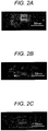
- Figures 2A, 2B and 2C depict external view images of Sample Steels A, B and C prepared by forging, respectively.
- the images demonstrate that the sample steels could be manufactured without suffering from cracking and defects due to forging.
- Figures 3A, 3B and 3C depict metal structure observation results of Sample Steels A, B and C after manufacturing, respectively.
- sample steels were each subjected to a heat treatment at 800°C, where the temperature is within a temperature range in which an embrittlement phase is readily precipitated. This was performed so as to evaluate the embrittlement phase precipitation under conditions of cooling during manufacturing and of reheating by welding.
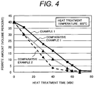
- Figure 4 is a graph illustrating how the amount of residual ferrite varies depending on the heat treatment time at 800°C.
- the graph is plotted with the abscissa indicating the heat treatment time and the ordinate indicating the ferrite amount.
- the ferrite amount was measured with a ferrite scope using magnetic induction.
- the tendency of intermetallic compound precipitation can be evaluated by evaluating the amount of residual ferrite. This is because the intermetallic compound precipitation which is one of embrittlement phase precipitations proceeds as a result of decomposition of the ferrite phase into an intermetallic compound phase and an austenite phase under a precipitation temperature condition.
- Figure 4 demonstrates that the stainless steel of Example 1 had a lower rate of ferrite phase decrease and less suffered from the decomposition of the ferrite phase than those of Comparative Examples 1 and 2.
- Figure 5A, 5B and 5C depict metal structure images of Sample Steel A, B and C, respectively, after a heat treatment at 800°C for 30 minutes.
- the figures demonstrate that an embrittlement phase 53 increased in addition to a ferrite phase 51 and an austenite phase 52.
- Sample Steel C included the embrittlement phase 53 as precipitated in a smaller amount than those of Sample Steels A and B as the comparative steels (Comparative Examples) and less suffered from the precipitation of the embrittlement phase 53.
- Sample Steel B included the embrittlement phase 53 in a larger amount.
- Figure 6 depicts Charpy impact value measurement results after a heat treatment at 800°C for 5 minutes.
- the Charpy impact value was measured according to Japanese Industrial Standard (JIS) Z2242 (2005). The measurement was performed by a procedure schematically illustrated as follows.
- Charpy test specimens having a size of 10 mm by 10 mm by 55 mm and having a 2-mm V-notch were sampled from each sample steel plate before and after the heat treatment from the longitudinal direction of the plate so that the central part should be the notched portion, and impact values of the test specimens were measured.
- Figure 6 demonstrates that Sample Steel C had a Charpy impact value after the heat treatment of higher than those of Sample Steels A and B as the comparative steels. This indicates that the suppression of intermetallic compound formation helped the steel to have better toughness.
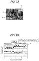
- Figures 7A, 7B , 7C and 7D depict energy-dispersive X-ray (EDX) analyses results at a grain boundary (alpha/gamma interface) after a heat treatment at 800°C for one minute.
- EDX energy-dispersive X-ray
- Figures 7A and 7B depict an electron photomicrograph and measurement results of concentration distributions of respective elements at the analysis position (along the analysis line) in the arrow direction in Fig. 7A , respectively, of Sample Steel A as the comparative steel.
- Figures 7C and 7D depict an electron photomicrograph and measurement results of concentration distributions of respective elements at the analysis position (along the analysis line) in the arrow direction in Fig. 7C , respectively, of Sample Steel C.
- Figures 7A and 7C depict fine structures of a ferrite phase 71 and an austenite phase 72 clearly, with a grain boundary indicated by dashed lines.
- the concentrations of respective elements were measured at the analysis position 73 indicated by the line in the arrow direction (from the austenite phase 72 to the ferrite phase 71).
- Figures 7B and 7D are plotted with the abscissa indicating the distance and the ordinate indicating the concentration.
- the comparative steel had high Mo and Cr concentrations in the vicinity of the grain boundary facing the ferrite phase.
- the sample steel C had a Ta concentration peak in the vicinity of the grain boundary facing the ferrite phase and exhibited lower Mo and Cr concentrations than those of the comparative steel in Fig. 7B .
- tantalum (Ta) preferably diffuses at the ferrite-austenite grain boundary and thereby inhibits the diffusion of Mo and Cr acting as intermetallic-compound-forming elements.
- sample steel C and comparative steels were each subjected to a heat treatment simulating a post weld heat treatment (PWHT) for residual stress relaxation, and how the heat treatment affects the residual stress and impact value was evaluated.
- PWHT post weld heat treatment
- a tensile residual stress was applied to each of Sample Steels A, B and C by subjecting them to surface grinding of the steel plate using a grindstone with a grain size of #46 at a rotation speed of 1440 rpm to a depth of cut of 0.01 mm and thereby imparting a highly deformed layer to the surface.
- the test samples each applied with the residual stress in the surface by surface grinding were subjected to a heat treatment at 650°C for 30 minutes simulating the PWHT, and how the heat treatment conditions affect the residual stress and mechanical properties was evaluated.
- Figure 8 depicts results of comparisons in residual stress between before and after the heat treatment.
- the residual stress values were measured for the ferrite phase and for the austenite phase, respectively.
- the measured values were multiplied by the volume ratio of each phase and averaged, and the average was defined as a macro-stress and evaluated.
- test samples were imparted with a tensile stress of about 900 to about 1100 MPa by the surface processing (surface grinding), but had a lower tensile stress of about 200 MPa after the heat treatment at 650°C for 30 minutes, indicating that the heat treatment gave a stress relaxation effect of about eight-tenths the initial stress.
- Figure 9 depicts comparison results in the Charpy impact test between before and after the heat treatment.
- Figure 9 demonstrates that the sample steel C had a better impact value than those of the comparative steels and maintained an impact value of about 100 J/cm 2 even after the heat treatment. Specifically, the sample steel C maintained an impact value of 100 J/cm 2 or more even after the heat treatment at 650°C for 30 minutes, where the heat treatment relaxed the residual stress by eight-tenths the initial stress.
- a pitting potentials was measured before and after the heat treatment (at 650°C for 30 minutes), and the results are indicated below.
- the pitting potential was measured according to JIS G0577 (2005).
- Figure 10 depicts a comparison in pitting potential among the sample steel C and the comparative steels.
- Figure 10 demonstrates that the order of pitting corrosion resistance (after the heat treatment) of the respective sample steels is as follows.
- Sample Steel C > Sample Steel B (comparative steel) > Sample Steel A (comparative steel; corresponding to customary steel S32750).
- the sample steel C had a pitting potential higher than that of the customary steel.
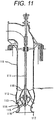
- Figure 11 is a cross-sectional view of a vertical mixed flow seawater pump.
- the vertical mixed flow seawater pump in Fig. 11 includes components such as a bell mouth 117 that reduces the drag of seawater coming in from a feed channel; a shaft 111 that transfers the rotative power of a driving motor; an impeller hub 115 that is fixed to the shaft 111; impeller vanes 113 that impart the rotative power of the driving motor to the seawater efficiently; a casing liner 114 that has a spherical inner wall so as to allow the impeller vanes 113 to have an always constant outer clearance; a casing 112 that converts the velocity energy of the seawater given by the impeller vanes 113 into pressure energy; a column pipe 119 that allows the pressurized seawater to pass therethrough; an impeller cap 116; and a cone 118.
- a bell mouth 117 that reduces the drag of seawater coming in from a feed channel
- a shaft 111 that transfers the rotative power of a driving motor
- an impeller hub 115 that is fixed to the shaft 111
- the casing liner 114 and the casing 112 were each formed from the steel of Example 1 by casting; whereas the impeller hub 115 and the impeller vanes 113 were each formed from the steel of Example 1 by forging. These steels after casting or forging were subjected to a solution heat treatment at 1100°C for one hour and then subjected to water cooling so as to have a two-phase composition including ferrite in an amount of 40% to 50% to give the structures.
- a junction between the casing liner 114 and the casing 112 and junctions between the impeller hub 115 and the impeller vanes 113 were bonded by metal inert gas arc welding (MIG welding). Weld heat affected zones were wrapped around with a band heater, heated up to 650°C, and subjected to a heat treatment at that temperature (650°C) for 30 minutes, followed by rapid cooling.
- MIG welding metal inert gas arc welding
- the residual stress of the weld heat affected zones was measured by X-ray residual stress measurement to find that the tensile stress was reduced down to 80 MPa.
- the steel of Example 1, as used, enabled the manufacturing of a seawater pump that less suffered from reduction in weld toughness, had a higher fatigue strength (better fatigue resistance), and had a longer working life.
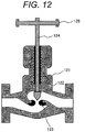
- Figure 12 is a cross-sectional view of a flow rate adjusting device.
- the flow rate adjusting device in Fig. 12 includes components such as a casing 121 that supports the entire device; a valve element 122 that controls a flow rate; a valve seat 123 into which the valve element 122 is fit; a handle 125; and a shaft 124 that controls the position of the valve element 122 by the rotation of the handle 125.
- the casing 121 was formed from the steel of Example 1 by casting.
- the steel of Example 1 enabled the manufacturing of a large-sized flow rate adjusting device having satisfactory corrosion resistance, as used.
- the flow rate adjusting device is usable in environments typically of seawater, petroleum, and chemical plants.
- impeller vane 114...casing liner, 115...impeller hub, 116...impeller cap, 117...bell mouth, 118...cone, 119...column pipe, 121...casing, 122...valve element, 123...valve seat, 124...shaft, 125...handle.
Landscapes
- Chemical & Material Sciences (AREA)
- Engineering & Computer Science (AREA)
- Materials Engineering (AREA)
- Mechanical Engineering (AREA)
- Metallurgy (AREA)
- Organic Chemistry (AREA)
- Physics & Mathematics (AREA)
- Thermal Sciences (AREA)
- Crystallography & Structural Chemistry (AREA)
- Heat Treatment Of Steel (AREA)
Claims (9)
- Duplex-Edelstahl, in Massenprozent bestehend aus:N in einem Gehalt von 0,05% bis 0,25%;C in einem Gehalt von 0,02% oder weniger;P in einem Gehalt von 0,02% oder weniger;Si in einem Gehalt von 0,5% oder weniger;Mn in einem Gehalt von 1,2% oder weniger;Ni in einem Gehalt von 6,0% bis 8,0%;Cr in einem Gehalt von 24,0% bis 26,0%;Mo in einem Gehalt von 3,0% bis 5,0%;W in einem Gehalt von 6,5% oder weniger; undTa in einem Gehalt von 0,2% bis 0,5%,wobei der Rest Fe und unvermeidbare Verunreinigungen ist.
- Duplex-Edelstahl nach Anspruch 1, der eine durch den im Folgenden wiedergegebenen Ausdruck festgelegte Lochfraß-Widerstandsfähigkeits-Äquivalenzzahl (PREW) von 40 oder mehr aufweist:

- Duplex-Edelstahlstruktur unter Verwendung des Duplex-Edelstahls nach einem der Ansprüche 1 und 2.
- Verfahren zur Gewinnung einer Duplex-Edelstahlstruktur, indem:durch Schmieden oder Gießen eine Struktur aus einem Duplex-Edelstahl nach einem der Ansprüche 1 und 2 gebildet wird; unddie gebildete Struktur einer Lösungs-Wärmebehandlung bei einer Temperatur von 950°C bis 1200°C über eine Zeitspanne von 30 Minuten bis 2 Stunden ausgesetzt wird, sodass sie ein Verhältnis der Austenit-Phase zur Ferrit-Phase von 0,2 bis 0,8 aufweist.
- Seetechnische Struktur, die eine Duplex-Edelstahlstruktur nach Anspruch 3 darstellt.
- Öl- und gastechnische Struktur, die eine Duplex-Edelstahlstruktur nach Anspruch 3 darstellt.
- Pumpenflügelrad, das eine Duplex-Edelstahlstruktur nach Anspruch 3 darstellt.
- Pumpengehäuse, das eine Duplex-Edelstahlstruktur nach Anspruch 3 darstellt.
- Ventilelement einer Strömungsraten-Einstellvorrichtung, das eine Duplex-Edelstahlstruktur nach Anspruch 3 darstellt.
Applications Claiming Priority (1)
| Application Number | Priority Date | Filing Date | Title |
|---|---|---|---|
| PCT/JP2013/073038 WO2015029167A1 (ja) | 2013-08-28 | 2013-08-28 | 二相ステンレス鋼並びにこれを用いた二相ステンレス鋼製構造物、海洋構造物、石油・ガス環境構造物、ポンプインペラ、ポンプケーシング及び流量調節弁の弁体 |
Publications (3)
| Publication Number | Publication Date |
|---|---|
| EP3040434A1 EP3040434A1 (de) | 2016-07-06 |
| EP3040434A4 EP3040434A4 (de) | 2017-05-03 |
| EP3040434B1 true EP3040434B1 (de) | 2019-03-27 |
Family
ID=52585786
Family Applications (1)
| Application Number | Title | Priority Date | Filing Date |
|---|---|---|---|
| EP13892680.3A Not-in-force EP3040434B1 (de) | 2013-08-28 | 2013-08-28 | Rostfreier duplexstahl und struktur aus dem rostfreien duplexstahl, meeresstruktur, erdöl/gas-umgebungsstruktur, pumpenlaufrad, pumpengehäuse und ventilkörper zur durchflusseinstellung damit |
Country Status (4)
| Country | Link |
|---|---|
| EP (1) | EP3040434B1 (de) |
| JP (1) | JP6286435B2 (de) |
| CN (1) | CN105492641A (de) |
| WO (1) | WO2015029167A1 (de) |
Families Citing this family (6)
| Publication number | Priority date | Publication date | Assignee | Title |
|---|---|---|---|---|
| JP6482074B2 (ja) * | 2014-09-02 | 2019-03-13 | 日本冶金工業株式会社 | 二相ステンレス鋼板とその製造方法 |
| JP6686320B2 (ja) * | 2015-08-05 | 2020-04-22 | 日本製鉄株式会社 | ステンレス鋼管の製造方法 |
| CN107312951A (zh) * | 2016-04-26 | 2017-11-03 | 天津碧宇舟机械制造有限公司 | 一种均质机用高强度转子及其制备方法 |
| CN107312979A (zh) * | 2016-04-26 | 2017-11-03 | 天津碧宇舟机械制造有限公司 | 一种大功率耐腐蚀泥浆泵叶轮及其制造方法 |
| CN105755397B (zh) * | 2016-05-24 | 2017-07-07 | 江苏金基特钢有限公司 | 一种耐腐蚀易成型特种钢的加工方法 |
| SE1950909A1 (en) | 2019-07-31 | 2021-02-01 | Ferritico Ab | Duplex steel with improved embrittlement properties and method of producing such |
Family Cites Families (7)
| Publication number | Priority date | Publication date | Assignee | Title |
|---|---|---|---|---|
| US4055448A (en) * | 1973-04-10 | 1977-10-25 | Daido Seiko Kabushiki Kaisha | Ferrite-austenite stainless steel |
| JPS5441214A (en) * | 1977-09-08 | 1979-04-02 | Nippon Yakin Kogyo Co Ltd | Twoophase highhstrength stainless steel |
| DE19628350B4 (de) * | 1996-07-13 | 2004-04-15 | Schmidt & Clemens Gmbh & Co | Verwendung einer rostfreien ferritisch-austenitischen Stahllegierung |
| JP4031992B2 (ja) * | 2001-04-27 | 2008-01-09 | リサーチ インスティチュート オブ インダストリアル サイエンス アンド テクノロジー | 優れた熱間加工性を持つ高マンガン二相ステンレス鋼及びその製造方法 |
| KR100460346B1 (ko) * | 2002-03-25 | 2004-12-08 | 이인성 | 금속간상의 형성이 억제된 내식성, 내취화성, 주조성 및열간가공성이 우수한 슈퍼 듀플렉스 스테인리스강 |
| EP2677054B1 (de) * | 2011-02-14 | 2020-03-25 | Nippon Steel Corporation | Duplex-edelstahl-blech oder -rohr und herstellungsverfahren dafür |
| JP5890330B2 (ja) * | 2013-01-15 | 2016-03-22 | 株式会社神戸製鋼所 | 二相ステンレス鋼材および二相ステンレス鋼管 |
-
2013
- 2013-08-28 JP JP2015533851A patent/JP6286435B2/ja not_active Expired - Fee Related
- 2013-08-28 EP EP13892680.3A patent/EP3040434B1/de not_active Not-in-force
- 2013-08-28 WO PCT/JP2013/073038 patent/WO2015029167A1/ja not_active Ceased
- 2013-08-28 CN CN201380079140.6A patent/CN105492641A/zh active Pending
Non-Patent Citations (1)
| Title |
|---|
| None * |
Also Published As
| Publication number | Publication date |
|---|---|
| CN105492641A (zh) | 2016-04-13 |
| EP3040434A4 (de) | 2017-05-03 |
| EP3040434A1 (de) | 2016-07-06 |
| JPWO2015029167A1 (ja) | 2017-03-02 |
| WO2015029167A1 (ja) | 2015-03-05 |
| JP6286435B2 (ja) | 2018-02-28 |
Similar Documents
| Publication | Publication Date | Title |
|---|---|---|
| JP6766887B2 (ja) | 油井用高強度ステンレス継目無鋼管およびその製造方法 | |
| EP3040434B1 (de) | Rostfreier duplexstahl und struktur aus dem rostfreien duplexstahl, meeresstruktur, erdöl/gas-umgebungsstruktur, pumpenlaufrad, pumpengehäuse und ventilkörper zur durchflusseinstellung damit | |
| EP3561131B1 (de) | Hochfestes nahtloses edelstahlrohr für ölbohrungen und herstellungsverfahren dafür | |
| JP6397432B2 (ja) | 合金を処理するための方法 | |
| KR101600735B1 (ko) | 내스케일 박리성이 우수한 내열 오스테나이트계 스테인리스강 및 스테인리스강관 | |
| EP0545753B1 (de) | Rostfreies Duplexstahl mit verbesserten Festigkeits- und Korrosionsbeständigkeitseigenschaften | |
| EP2725112B1 (de) | Aufkohlungsresistentes metallmaterial und anwendungen des aufkohlungsresistenten metallmaterials | |
| EP3321389B1 (de) | Hochfestes nahtloses edelstahlrohr und herstellungsverfahren dafür | |
| JP5613152B2 (ja) | ステンレス鋼製品、その製品の使用およびその製造方法 | |
| EP2128283B1 (de) | Nickelbasierte Guss-Superlegierung und Gusskomponente für eine Dampfturbine mit dieser Legierung | |
| EP3575427B1 (de) | Zweiphasiger edelstahlarmierter stahl und verfahren zur herstellung davon | |
| JP5657523B2 (ja) | 超々臨界ボイラヘッダ合金および製造方法 | |
| EP2977478B1 (de) | Nickel-legierung plattierter stahl mit hervorragenden korngrenzen-korrosionsbeständigkeit und verfahren zur herstellung davon | |
| JP6201724B2 (ja) | Ni基耐熱合金部材およびNi基耐熱合金素材 | |
| CN104411850B (zh) | 双相不锈钢 | |
| JP2005023353A (ja) | 高温水環境用オーステナイトステンレス鋼 | |
| EA009108B1 (ru) | Двухфазная коррозионно-стойкая легированная сталь для использования в морской воде | |
| JPWO2018003823A1 (ja) | オーステナイト系ステンレス鋼 | |
| EP1313888B1 (de) | Preiswerte, korrosion und hitzebeständige legierung für diesel-brennkraftmaschine | |
| JP6085989B2 (ja) | Ni基耐熱合金部材およびNi基耐熱合金素材 | |
| JP2017036477A (ja) | オーステナイト系耐熱合金部材およびその製造方法 | |
| EP3441492A1 (de) | Auf chrom basierende zweiphasige legierung und produkt unter verwendung der zweiphasigen legierung | |
| CA3066336C (en) | Ni-based alloy pipe for nuclear power | |
| JP7207557B2 (ja) | 油井管用ステンレス継目無鋼管およびその製造方法 | |
| JP3933089B2 (ja) | 低合金鋼 |
Legal Events
| Date | Code | Title | Description |
|---|---|---|---|
| PUAI | Public reference made under article 153(3) epc to a published international application that has entered the european phase |
Free format text: ORIGINAL CODE: 0009012 |
|
| 17P | Request for examination filed |
Effective date: 20160222 |
|
| AK | Designated contracting states |
Kind code of ref document: A1 Designated state(s): AL AT BE BG CH CY CZ DE DK EE ES FI FR GB GR HR HU IE IS IT LI LT LU LV MC MK MT NL NO PL PT RO RS SE SI SK SM TR |
|
| AX | Request for extension of the european patent |
Extension state: BA ME |
|
| DAX | Request for extension of the european patent (deleted) | ||
| A4 | Supplementary search report drawn up and despatched |
Effective date: 20170330 |
|
| RIC1 | Information provided on ipc code assigned before grant |
Ipc: C22C 38/48 20060101ALI20170325BHEP Ipc: C22C 38/02 20060101ALI20170325BHEP Ipc: C22C 38/00 20060101AFI20170325BHEP Ipc: C22C 38/06 20060101ALI20170325BHEP Ipc: C22C 38/04 20060101ALI20170325BHEP Ipc: C22C 38/58 20060101ALI20170325BHEP Ipc: C22C 38/44 20060101ALI20170325BHEP Ipc: C22C 38/42 20060101ALI20170325BHEP Ipc: C21D 6/00 20060101ALI20170325BHEP |
|
| STAA | Information on the status of an ep patent application or granted ep patent |
Free format text: STATUS: EXAMINATION IS IN PROGRESS |
|
| 17Q | First examination report despatched |
Effective date: 20171106 |
|
| GRAP | Despatch of communication of intention to grant a patent |
Free format text: ORIGINAL CODE: EPIDOSNIGR1 |
|
| STAA | Information on the status of an ep patent application or granted ep patent |
Free format text: STATUS: GRANT OF PATENT IS INTENDED |
|
| INTG | Intention to grant announced |
Effective date: 20181123 |
|
| GRAS | Grant fee paid |
Free format text: ORIGINAL CODE: EPIDOSNIGR3 |
|
| GRAA | (expected) grant |
Free format text: ORIGINAL CODE: 0009210 |
|
| STAA | Information on the status of an ep patent application or granted ep patent |
Free format text: STATUS: THE PATENT HAS BEEN GRANTED |
|
| AK | Designated contracting states |
Kind code of ref document: B1 Designated state(s): AL AT BE BG CH CY CZ DE DK EE ES FI FR GB GR HR HU IE IS IT LI LT LU LV MC MK MT NL NO PL PT RO RS SE SI SK SM TR |
|
| REG | Reference to a national code |
Ref country code: GB Ref legal event code: FG4D |
|
| REG | Reference to a national code |
Ref country code: CH Ref legal event code: EP |
|
| REG | Reference to a national code |
Ref country code: AT Ref legal event code: REF Ref document number: 1113175 Country of ref document: AT Kind code of ref document: T Effective date: 20190415 |
|
| REG | Reference to a national code |
Ref country code: IE Ref legal event code: FG4D |
|
| REG | Reference to a national code |
Ref country code: DE Ref legal event code: R096 Ref document number: 602013053142 Country of ref document: DE |
|
| PG25 | Lapsed in a contracting state [announced via postgrant information from national office to epo] |
Ref country code: NO Free format text: LAPSE BECAUSE OF FAILURE TO SUBMIT A TRANSLATION OF THE DESCRIPTION OR TO PAY THE FEE WITHIN THE PRESCRIBED TIME-LIMIT Effective date: 20190627 Ref country code: FI Free format text: LAPSE BECAUSE OF FAILURE TO SUBMIT A TRANSLATION OF THE DESCRIPTION OR TO PAY THE FEE WITHIN THE PRESCRIBED TIME-LIMIT Effective date: 20190327 Ref country code: LT Free format text: LAPSE BECAUSE OF FAILURE TO SUBMIT A TRANSLATION OF THE DESCRIPTION OR TO PAY THE FEE WITHIN THE PRESCRIBED TIME-LIMIT Effective date: 20190327 Ref country code: SE Free format text: LAPSE BECAUSE OF FAILURE TO SUBMIT A TRANSLATION OF THE DESCRIPTION OR TO PAY THE FEE WITHIN THE PRESCRIBED TIME-LIMIT Effective date: 20190327 |
|
| REG | Reference to a national code |
Ref country code: NL Ref legal event code: MP Effective date: 20190327 |
|
| PG25 | Lapsed in a contracting state [announced via postgrant information from national office to epo] |
Ref country code: BG Free format text: LAPSE BECAUSE OF FAILURE TO SUBMIT A TRANSLATION OF THE DESCRIPTION OR TO PAY THE FEE WITHIN THE PRESCRIBED TIME-LIMIT Effective date: 20190627 Ref country code: HR Free format text: LAPSE BECAUSE OF FAILURE TO SUBMIT A TRANSLATION OF THE DESCRIPTION OR TO PAY THE FEE WITHIN THE PRESCRIBED TIME-LIMIT Effective date: 20190327 Ref country code: GR Free format text: LAPSE BECAUSE OF FAILURE TO SUBMIT A TRANSLATION OF THE DESCRIPTION OR TO PAY THE FEE WITHIN THE PRESCRIBED TIME-LIMIT Effective date: 20190628 Ref country code: LV Free format text: LAPSE BECAUSE OF FAILURE TO SUBMIT A TRANSLATION OF THE DESCRIPTION OR TO PAY THE FEE WITHIN THE PRESCRIBED TIME-LIMIT Effective date: 20190327 Ref country code: RS Free format text: LAPSE BECAUSE OF FAILURE TO SUBMIT A TRANSLATION OF THE DESCRIPTION OR TO PAY THE FEE WITHIN THE PRESCRIBED TIME-LIMIT Effective date: 20190327 Ref country code: NL Free format text: LAPSE BECAUSE OF FAILURE TO SUBMIT A TRANSLATION OF THE DESCRIPTION OR TO PAY THE FEE WITHIN THE PRESCRIBED TIME-LIMIT Effective date: 20190327 |
|
| REG | Reference to a national code |
Ref country code: AT Ref legal event code: MK05 Ref document number: 1113175 Country of ref document: AT Kind code of ref document: T Effective date: 20190327 |
|
| PG25 | Lapsed in a contracting state [announced via postgrant information from national office to epo] |
Ref country code: RO Free format text: LAPSE BECAUSE OF FAILURE TO SUBMIT A TRANSLATION OF THE DESCRIPTION OR TO PAY THE FEE WITHIN THE PRESCRIBED TIME-LIMIT Effective date: 20190327 Ref country code: CZ Free format text: LAPSE BECAUSE OF FAILURE TO SUBMIT A TRANSLATION OF THE DESCRIPTION OR TO PAY THE FEE WITHIN THE PRESCRIBED TIME-LIMIT Effective date: 20190327 Ref country code: SK Free format text: LAPSE BECAUSE OF FAILURE TO SUBMIT A TRANSLATION OF THE DESCRIPTION OR TO PAY THE FEE WITHIN THE PRESCRIBED TIME-LIMIT Effective date: 20190327 Ref country code: ES Free format text: LAPSE BECAUSE OF FAILURE TO SUBMIT A TRANSLATION OF THE DESCRIPTION OR TO PAY THE FEE WITHIN THE PRESCRIBED TIME-LIMIT Effective date: 20190327 Ref country code: PT Free format text: LAPSE BECAUSE OF FAILURE TO SUBMIT A TRANSLATION OF THE DESCRIPTION OR TO PAY THE FEE WITHIN THE PRESCRIBED TIME-LIMIT Effective date: 20190727 Ref country code: AL Free format text: LAPSE BECAUSE OF FAILURE TO SUBMIT A TRANSLATION OF THE DESCRIPTION OR TO PAY THE FEE WITHIN THE PRESCRIBED TIME-LIMIT Effective date: 20190327 Ref country code: EE Free format text: LAPSE BECAUSE OF FAILURE TO SUBMIT A TRANSLATION OF THE DESCRIPTION OR TO PAY THE FEE WITHIN THE PRESCRIBED TIME-LIMIT Effective date: 20190327 |
|
| PG25 | Lapsed in a contracting state [announced via postgrant information from national office to epo] |
Ref country code: SM Free format text: LAPSE BECAUSE OF FAILURE TO SUBMIT A TRANSLATION OF THE DESCRIPTION OR TO PAY THE FEE WITHIN THE PRESCRIBED TIME-LIMIT Effective date: 20190327 Ref country code: PL Free format text: LAPSE BECAUSE OF FAILURE TO SUBMIT A TRANSLATION OF THE DESCRIPTION OR TO PAY THE FEE WITHIN THE PRESCRIBED TIME-LIMIT Effective date: 20190327 |
|
| PG25 | Lapsed in a contracting state [announced via postgrant information from national office to epo] |
Ref country code: IS Free format text: LAPSE BECAUSE OF FAILURE TO SUBMIT A TRANSLATION OF THE DESCRIPTION OR TO PAY THE FEE WITHIN THE PRESCRIBED TIME-LIMIT Effective date: 20190727 Ref country code: AT Free format text: LAPSE BECAUSE OF FAILURE TO SUBMIT A TRANSLATION OF THE DESCRIPTION OR TO PAY THE FEE WITHIN THE PRESCRIBED TIME-LIMIT Effective date: 20190327 |
|
| REG | Reference to a national code |
Ref country code: DE Ref legal event code: R097 Ref document number: 602013053142 Country of ref document: DE |
|
| PG25 | Lapsed in a contracting state [announced via postgrant information from national office to epo] |
Ref country code: DK Free format text: LAPSE BECAUSE OF FAILURE TO SUBMIT A TRANSLATION OF THE DESCRIPTION OR TO PAY THE FEE WITHIN THE PRESCRIBED TIME-LIMIT Effective date: 20190327 |
|
| PLBE | No opposition filed within time limit |
Free format text: ORIGINAL CODE: 0009261 |
|
| STAA | Information on the status of an ep patent application or granted ep patent |
Free format text: STATUS: NO OPPOSITION FILED WITHIN TIME LIMIT |
|
| PG25 | Lapsed in a contracting state [announced via postgrant information from national office to epo] |
Ref country code: SI Free format text: LAPSE BECAUSE OF FAILURE TO SUBMIT A TRANSLATION OF THE DESCRIPTION OR TO PAY THE FEE WITHIN THE PRESCRIBED TIME-LIMIT Effective date: 20190327 |
|
| REG | Reference to a national code |
Ref country code: DE Ref legal event code: R119 Ref document number: 602013053142 Country of ref document: DE |
|
| 26N | No opposition filed |
Effective date: 20200103 |
|
| PG25 | Lapsed in a contracting state [announced via postgrant information from national office to epo] |
Ref country code: TR Free format text: LAPSE BECAUSE OF FAILURE TO SUBMIT A TRANSLATION OF THE DESCRIPTION OR TO PAY THE FEE WITHIN THE PRESCRIBED TIME-LIMIT Effective date: 20190327 |
|
| PG25 | Lapsed in a contracting state [announced via postgrant information from national office to epo] |
Ref country code: CH Free format text: LAPSE BECAUSE OF NON-PAYMENT OF DUE FEES Effective date: 20190831 Ref country code: LI Free format text: LAPSE BECAUSE OF NON-PAYMENT OF DUE FEES Effective date: 20190831 Ref country code: MC Free format text: LAPSE BECAUSE OF FAILURE TO SUBMIT A TRANSLATION OF THE DESCRIPTION OR TO PAY THE FEE WITHIN THE PRESCRIBED TIME-LIMIT Effective date: 20190327 Ref country code: LU Free format text: LAPSE BECAUSE OF NON-PAYMENT OF DUE FEES Effective date: 20190828 |
|
| REG | Reference to a national code |
Ref country code: BE Ref legal event code: MM Effective date: 20190831 |
|
| PG25 | Lapsed in a contracting state [announced via postgrant information from national office to epo] |
Ref country code: DE Free format text: LAPSE BECAUSE OF NON-PAYMENT OF DUE FEES Effective date: 20200303 Ref country code: IE Free format text: LAPSE BECAUSE OF NON-PAYMENT OF DUE FEES Effective date: 20190828 Ref country code: FR Free format text: LAPSE BECAUSE OF NON-PAYMENT OF DUE FEES Effective date: 20190831 |
|
| PG25 | Lapsed in a contracting state [announced via postgrant information from national office to epo] |
Ref country code: BE Free format text: LAPSE BECAUSE OF NON-PAYMENT OF DUE FEES Effective date: 20190831 |
|
| PG25 | Lapsed in a contracting state [announced via postgrant information from national office to epo] |
Ref country code: CY Free format text: LAPSE BECAUSE OF FAILURE TO SUBMIT A TRANSLATION OF THE DESCRIPTION OR TO PAY THE FEE WITHIN THE PRESCRIBED TIME-LIMIT Effective date: 20190327 |
|
| PG25 | Lapsed in a contracting state [announced via postgrant information from national office to epo] |
Ref country code: HU Free format text: LAPSE BECAUSE OF FAILURE TO SUBMIT A TRANSLATION OF THE DESCRIPTION OR TO PAY THE FEE WITHIN THE PRESCRIBED TIME-LIMIT; INVALID AB INITIO Effective date: 20130828 Ref country code: MT Free format text: LAPSE BECAUSE OF FAILURE TO SUBMIT A TRANSLATION OF THE DESCRIPTION OR TO PAY THE FEE WITHIN THE PRESCRIBED TIME-LIMIT Effective date: 20190327 |
|
| PGFP | Annual fee paid to national office [announced via postgrant information from national office to epo] |
Ref country code: IT Payment date: 20210712 Year of fee payment: 9 |
|
| PGFP | Annual fee paid to national office [announced via postgrant information from national office to epo] |
Ref country code: GB Payment date: 20210721 Year of fee payment: 9 |
|
| PG25 | Lapsed in a contracting state [announced via postgrant information from national office to epo] |
Ref country code: MK Free format text: LAPSE BECAUSE OF FAILURE TO SUBMIT A TRANSLATION OF THE DESCRIPTION OR TO PAY THE FEE WITHIN THE PRESCRIBED TIME-LIMIT Effective date: 20190327 |
|
| GBPC | Gb: european patent ceased through non-payment of renewal fee |
Effective date: 20220828 |
|
| PG25 | Lapsed in a contracting state [announced via postgrant information from national office to epo] |
Ref country code: IT Free format text: LAPSE BECAUSE OF NON-PAYMENT OF DUE FEES Effective date: 20220828 |
|
| PG25 | Lapsed in a contracting state [announced via postgrant information from national office to epo] |
Ref country code: GB Free format text: LAPSE BECAUSE OF NON-PAYMENT OF DUE FEES Effective date: 20220828 |