EP3040405A1 - Method for improving propylene recovery from fluid catalytic cracker unit - Google Patents
Method for improving propylene recovery from fluid catalytic cracker unit Download PDFInfo
- Publication number
- EP3040405A1 EP3040405A1 EP14307211.4A EP14307211A EP3040405A1 EP 3040405 A1 EP3040405 A1 EP 3040405A1 EP 14307211 A EP14307211 A EP 14307211A EP 3040405 A1 EP3040405 A1 EP 3040405A1
- Authority
- EP
- European Patent Office
- Prior art keywords
- stream
- liquid
- hydrocarbons
- rich
- absorber
- Prior art date
- Legal status (The legal status is an assumption and is not a legal conclusion. Google has not performed a legal analysis and makes no representation as to the accuracy of the status listed.)
- Withdrawn
Links
- QQONPFPTGQHPMA-UHFFFAOYSA-N propylene Natural products CC=C QQONPFPTGQHPMA-UHFFFAOYSA-N 0.000 title claims abstract description 99
- 125000004805 propylene group Chemical group [H]C([H])([H])C([H])([*:1])C([H])([H])[*:2] 0.000 title claims abstract description 99
- 238000000034 method Methods 0.000 title claims abstract description 29
- 238000011084 recovery Methods 0.000 title claims abstract description 20
- 230000003197 catalytic effect Effects 0.000 title claims abstract description 12
- 239000012530 fluid Substances 0.000 title claims abstract description 12
- 238000009434 installation Methods 0.000 claims abstract description 26
- 150000002430 hydrocarbons Chemical class 0.000 claims description 140
- 239000007788 liquid Substances 0.000 claims description 116
- 229930195733 hydrocarbon Natural products 0.000 claims description 112
- 239000006096 absorbing agent Substances 0.000 claims description 102
- 239000007789 gas Substances 0.000 claims description 95
- 238000011144 upstream manufacturing Methods 0.000 claims description 51
- 239000003381 stabilizer Substances 0.000 claims description 48
- 239000003915 liquefied petroleum gas Substances 0.000 claims description 15
- 238000000926 separation method Methods 0.000 claims description 15
- 150000001875 compounds Chemical class 0.000 claims description 13
- 230000006835 compression Effects 0.000 claims description 13
- 238000007906 compression Methods 0.000 claims description 13
- 238000009833 condensation Methods 0.000 claims description 13
- 230000005494 condensation Effects 0.000 claims description 13
- 238000001816 cooling Methods 0.000 claims description 11
- 239000002737 fuel gas Substances 0.000 claims description 8
- 238000002156 mixing Methods 0.000 claims description 7
- 239000004215 Carbon black (E152) Substances 0.000 claims description 6
- 238000004064 recycling Methods 0.000 claims description 5
- 238000010438 heat treatment Methods 0.000 claims description 4
- 239000000498 cooling water Substances 0.000 claims 2
- 239000003502 gasoline Substances 0.000 description 7
- 238000010521 absorption reaction Methods 0.000 description 3
- 238000010992 reflux Methods 0.000 description 3
- XLYOFNOQVPJJNP-UHFFFAOYSA-N water Substances O XLYOFNOQVPJJNP-UHFFFAOYSA-N 0.000 description 3
- IJGRMHOSHXDMSA-UHFFFAOYSA-N Atomic nitrogen Chemical compound N#N IJGRMHOSHXDMSA-UHFFFAOYSA-N 0.000 description 2
- 238000007796 conventional method Methods 0.000 description 2
- 239000000463 material Substances 0.000 description 2
- 239000004743 Polypropylene Substances 0.000 description 1
- 230000002745 absorbent Effects 0.000 description 1
- 239000002250 absorbent Substances 0.000 description 1
- 238000010586 diagram Methods 0.000 description 1
- 239000012535 impurity Substances 0.000 description 1
- 239000007791 liquid phase Substances 0.000 description 1
- 238000004519 manufacturing process Methods 0.000 description 1
- 239000000178 monomer Substances 0.000 description 1
- 229910052757 nitrogen Inorganic materials 0.000 description 1
- -1 polypropylene Polymers 0.000 description 1
- 229920001155 polypropylene Polymers 0.000 description 1
- 239000002994 raw material Substances 0.000 description 1
Images
Classifications
-
- C—CHEMISTRY; METALLURGY
- C07—ORGANIC CHEMISTRY
- C07C—ACYCLIC OR CARBOCYCLIC COMPOUNDS
- C07C7/00—Purification; Separation; Use of additives
- C07C7/005—Processes comprising at least two steps in series
-
- B—PERFORMING OPERATIONS; TRANSPORTING
- B01—PHYSICAL OR CHEMICAL PROCESSES OR APPARATUS IN GENERAL
- B01D—SEPARATION
- B01D5/00—Condensation of vapours; Recovering volatile solvents by condensation
- B01D5/0057—Condensation of vapours; Recovering volatile solvents by condensation in combination with other processes
- B01D5/0075—Condensation of vapours; Recovering volatile solvents by condensation in combination with other processes with heat exchanging
-
- B—PERFORMING OPERATIONS; TRANSPORTING
- B01—PHYSICAL OR CHEMICAL PROCESSES OR APPARATUS IN GENERAL
- B01D—SEPARATION
- B01D53/00—Separation of gases or vapours; Recovering vapours of volatile solvents from gases; Chemical or biological purification of waste gases, e.g. engine exhaust gases, smoke, fumes, flue gases, aerosols
- B01D53/14—Separation of gases or vapours; Recovering vapours of volatile solvents from gases; Chemical or biological purification of waste gases, e.g. engine exhaust gases, smoke, fumes, flue gases, aerosols by absorption
- B01D53/1431—Pretreatment by other processes
- B01D53/145—Pretreatment by separation of solid or liquid material
-
- C—CHEMISTRY; METALLURGY
- C07—ORGANIC CHEMISTRY
- C07C—ACYCLIC OR CARBOCYCLIC COMPOUNDS
- C07C7/00—Purification; Separation; Use of additives
- C07C7/04—Purification; Separation; Use of additives by distillation
-
- C—CHEMISTRY; METALLURGY
- C07—ORGANIC CHEMISTRY
- C07C—ACYCLIC OR CARBOCYCLIC COMPOUNDS
- C07C7/00—Purification; Separation; Use of additives
- C07C7/09—Purification; Separation; Use of additives by fractional condensation
-
- C—CHEMISTRY; METALLURGY
- C07—ORGANIC CHEMISTRY
- C07C—ACYCLIC OR CARBOCYCLIC COMPOUNDS
- C07C7/00—Purification; Separation; Use of additives
- C07C7/11—Purification; Separation; Use of additives by absorption, i.e. purification or separation of gaseous hydrocarbons with the aid of liquids
-
- C—CHEMISTRY; METALLURGY
- C10—PETROLEUM, GAS OR COKE INDUSTRIES; TECHNICAL GASES CONTAINING CARBON MONOXIDE; FUELS; LUBRICANTS; PEAT
- C10G—CRACKING HYDROCARBON OILS; PRODUCTION OF LIQUID HYDROCARBON MIXTURES, e.g. BY DESTRUCTIVE HYDROGENATION, OLIGOMERISATION, POLYMERISATION; RECOVERY OF HYDROCARBON OILS FROM OIL-SHALE, OIL-SAND, OR GASES; REFINING MIXTURES MAINLY CONSISTING OF HYDROCARBONS; REFORMING OF NAPHTHA; MINERAL WAXES
- C10G7/00—Distillation of hydrocarbon oils
- C10G7/02—Stabilising gasoline by removing gases by fractioning
-
- C—CHEMISTRY; METALLURGY
- C10—PETROLEUM, GAS OR COKE INDUSTRIES; TECHNICAL GASES CONTAINING CARBON MONOXIDE; FUELS; LUBRICANTS; PEAT
- C10G—CRACKING HYDROCARBON OILS; PRODUCTION OF LIQUID HYDROCARBON MIXTURES, e.g. BY DESTRUCTIVE HYDROGENATION, OLIGOMERISATION, POLYMERISATION; RECOVERY OF HYDROCARBON OILS FROM OIL-SHALE, OIL-SAND, OR GASES; REFINING MIXTURES MAINLY CONSISTING OF HYDROCARBONS; REFORMING OF NAPHTHA; MINERAL WAXES
- C10G70/00—Working-up undefined normally gaseous mixtures obtained by processes covered by groups C10G9/00, C10G11/00, C10G15/00, C10G47/00, C10G51/00
- C10G70/04—Working-up undefined normally gaseous mixtures obtained by processes covered by groups C10G9/00, C10G11/00, C10G15/00, C10G47/00, C10G51/00 by physical processes
- C10G70/043—Working-up undefined normally gaseous mixtures obtained by processes covered by groups C10G9/00, C10G11/00, C10G15/00, C10G47/00, C10G51/00 by physical processes by fractional condensation
-
- C—CHEMISTRY; METALLURGY
- C10—PETROLEUM, GAS OR COKE INDUSTRIES; TECHNICAL GASES CONTAINING CARBON MONOXIDE; FUELS; LUBRICANTS; PEAT
- C10G—CRACKING HYDROCARBON OILS; PRODUCTION OF LIQUID HYDROCARBON MIXTURES, e.g. BY DESTRUCTIVE HYDROGENATION, OLIGOMERISATION, POLYMERISATION; RECOVERY OF HYDROCARBON OILS FROM OIL-SHALE, OIL-SAND, OR GASES; REFINING MIXTURES MAINLY CONSISTING OF HYDROCARBONS; REFORMING OF NAPHTHA; MINERAL WAXES
- C10G70/00—Working-up undefined normally gaseous mixtures obtained by processes covered by groups C10G9/00, C10G11/00, C10G15/00, C10G47/00, C10G51/00
- C10G70/04—Working-up undefined normally gaseous mixtures obtained by processes covered by groups C10G9/00, C10G11/00, C10G15/00, C10G47/00, C10G51/00 by physical processes
- C10G70/06—Working-up undefined normally gaseous mixtures obtained by processes covered by groups C10G9/00, C10G11/00, C10G15/00, C10G47/00, C10G51/00 by physical processes by gas-liquid contact
-
- C—CHEMISTRY; METALLURGY
- C10—PETROLEUM, GAS OR COKE INDUSTRIES; TECHNICAL GASES CONTAINING CARBON MONOXIDE; FUELS; LUBRICANTS; PEAT
- C10G—CRACKING HYDROCARBON OILS; PRODUCTION OF LIQUID HYDROCARBON MIXTURES, e.g. BY DESTRUCTIVE HYDROGENATION, OLIGOMERISATION, POLYMERISATION; RECOVERY OF HYDROCARBON OILS FROM OIL-SHALE, OIL-SAND, OR GASES; REFINING MIXTURES MAINLY CONSISTING OF HYDROCARBONS; REFORMING OF NAPHTHA; MINERAL WAXES
- C10G2400/00—Products obtained by processes covered by groups C10G9/00 - C10G69/14
- C10G2400/20—C2-C4 olefins
-
- C—CHEMISTRY; METALLURGY
- C10—PETROLEUM, GAS OR COKE INDUSTRIES; TECHNICAL GASES CONTAINING CARBON MONOXIDE; FUELS; LUBRICANTS; PEAT
- C10G—CRACKING HYDROCARBON OILS; PRODUCTION OF LIQUID HYDROCARBON MIXTURES, e.g. BY DESTRUCTIVE HYDROGENATION, OLIGOMERISATION, POLYMERISATION; RECOVERY OF HYDROCARBON OILS FROM OIL-SHALE, OIL-SAND, OR GASES; REFINING MIXTURES MAINLY CONSISTING OF HYDROCARBONS; REFORMING OF NAPHTHA; MINERAL WAXES
- C10G2400/00—Products obtained by processes covered by groups C10G9/00 - C10G69/14
- C10G2400/26—Fuel gas
-
- C—CHEMISTRY; METALLURGY
- C10—PETROLEUM, GAS OR COKE INDUSTRIES; TECHNICAL GASES CONTAINING CARBON MONOXIDE; FUELS; LUBRICANTS; PEAT
- C10G—CRACKING HYDROCARBON OILS; PRODUCTION OF LIQUID HYDROCARBON MIXTURES, e.g. BY DESTRUCTIVE HYDROGENATION, OLIGOMERISATION, POLYMERISATION; RECOVERY OF HYDROCARBON OILS FROM OIL-SHALE, OIL-SAND, OR GASES; REFINING MIXTURES MAINLY CONSISTING OF HYDROCARBONS; REFORMING OF NAPHTHA; MINERAL WAXES
- C10G2400/00—Products obtained by processes covered by groups C10G9/00 - C10G69/14
- C10G2400/28—Propane and butane
Definitions
- the present invention relates to a method for treating a cracked gas stream from a fluid catalytic cracker unit (FCCU) and more particularly to a method for improving propylene recovery from gas stream from a fluid catalytic cracker unit.
- FCCU fluid catalytic cracker unit
- Propylene is a raw material for a wide variety of products. Propylene is principally used as monomer for the production of polypropylene. There is thus a strong market demand for propylene.
- FCCU Fluid Catalytic Cracker Unit
- LPG Liquefied Petroleum Gas
- An object of the invention is therefore to provide a method for improving propylene recovery from streams from fluid catalytic cracker unit, for example in a range of 2 to 3 wt% of propylene potential compared to conventional methods.
- Another object of the invention is also to provide an installation in order to implement this method.
- the subject matter of the invention is a method for treating a cracked streams (gas stream and liquid stream) stemming from a fluid catalytic cracker unit (FCCU) comprising the following steps:
- the stream rich in C5 and C6 is also poor in C7+ hydrocarbons.
- the inventors have discovered that the stream rich in C5 and C6 hydrocarbons and poor in C7+ hydrocarbons has a good affinity to absorb propylene from light off gases. It thus enables to increase propylene recovery in the propylene absorber column.
- the inventors have discovered that lowering the temperature of stream rich in C5 and C6 hydrocarbons enhances the capability of the stream to absorb more propylene from light off gases. It thus enables to increase propylene recovery in the propylene absorber column.
- the temperature of stream rich in C5 and C6 hydrocarbons sent into propylene absorber is comprised between 20 and 40°C, preferably between 28 and 32 °C.
- the inventors have discovered that lowering the temperature of gas stream recovered from top of the primary absorber before introducing it into propylene absorber enhances propylene absorption. It thus enables to increase propylene recovery in the propylene absorber column.
- the temperature of the gas stream recovered from top of the primary absorber before introducing it into propylene absorber enhances propylene absorption is at a temperature lower than or equal to 40°C, preferably between 25 and 40°C, more preferably between 38 and 40 °C.
- the method according to the invention can comprise a further step of mixing the liquid rich in C3 hydrocarbons, especially propylene, from the propylene absorber column with the stream resulted from the compression and partial condensation of the gas stream from the main fractionator before the separation of the resulting stream into the upstream liquid and the upstream gas.
- This further step enables to improve the recovering of C3 hydrocarbons, and especially propylene, compared to conventional scheme.
- the method of the invention may further comprise one or more of the following features, taken individually or according to all technically possible combination(s):
- the first gas stream is cooled before being introduced into the propylene absorber, this enables shifting thermodynamic equilibrium in favor of more propylene absorption into the liquid phase.
- the temperature of the first gas stream before introduction into the propylene absorber is between 35 and 50°C, preferably between 38 and 43°C, more preferably between 38 and 40°C.
- the sponge absorber enables to capture gasoline range material, principally C5 compounds, which can be lost in the gases coming from the primary absorber.
- the resulting stream is a rich oil which can be sent to main fractionator column.
- the liquid stream rich in C5, C6 and C7+ hydrocarbons recovered from the stabilizer column bottom can be separated in two liquid stream, a stabilized gasoline which can be stored and a recycle gasoline which can be sent to the primary absorber.
- the implementation of this method enables an improvement of the propylene recovery from gas stream from fluid catalytic cracker unit in a range of 2 to 3 wt% compared to the conventional method.
- FCCU fluid catalytic cracker unit
- the installation may further comprise means for recycling and mixing the liquid stream rich in C3 hydrocarbons from the propylene absorber with the stream resulting from the compression and partial condensation of the gas stream from the main fractionator before the separation of the resulting stream into the upstream liquid and the upstream gas.
- the installation of the invention may further comprise one or more of the following features, taken individually or according to all technically possible combination(s):
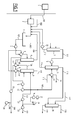
- figure 1 is the functional block diagram of installation according to the invention, intended for applying the method according to the invention.
- the installation according to the invention is illustrated in figure 1 .
- This installation comprises a compressor/condenser 2, a separator 3, a stripper 6 for producing a stream rich in C2 compound 104 and a stream rich in C3+ hydrocarbons 105.
- the installation further comprises a stabilizer column 9 to produce a stream 110 rich in C3 and C4 hydrocarbons, a side stream 106 rich in C5 and C6 compounds and a bottom stream 107 rich in C5, C6 and C7+ compounds.
- the installation also comprises a primary absorber 13 and a propylene absorber 15 which enables to recover a liquid stream 115 rich in C3 hydrocarbons, especially propylene.
- a sponge absorber 16 enables to absorb in a lean oil 117 gasoline range material (C5+ compounds) to produce a rich oil 119 and a fuel gas 118.
- the installation optionally comprises a treatment unit of the stream 110 rich in C3 and C4 hydrocarbons.
- This unit comprises a condenser 17 and a stabilizer receiver 19 to produce LPG 120 comprising of C3 and C4 hydrocarbons and a stream 121 as a reflux to stabilizer column (9) comprising C3 and C4 hydrocarbons.
- the propylene absorber 15 is in between the primary absorber 13 and the sponge absorber 16.
- the method according to the invention starts by providing a gas stream 101 having wide range of hydrocarbons from C1 to C7+ with impurities like nitrogen, CO 2 , H 2 S, water vapour etc. from the main fractionator column overhead receiver of an FCCU 1.
- the gas stream 101 has generally a temperature comprised between 30 and 50°C, preferably between 38 and 43°C, and a pressure generally comprised between 0.5 and 2.5 barg, especially between 1.0 and 2.0 barg.
- Its molar content in propylene is generally comprised between 15 and 50 mol%, preferably between 25 and 45 mol%.
- the gas stream 101 is compressed and partially condensed into a compressor/condenser 2.
- the pressure of the compressed gas stream is for example comprised between 14 barg and 16 barg and the liquid molar content is higher than 70 mol%, preferably comprised between 70 and 80 mol%.
- the resulting stream is introduced into a separator 3 which enables to recover an upstream liquid 102 and an upstream gas 103.
- the separator 3 is preferably a high pressure receiver, operating for example at a pressure higher than 14 barg.
- the upstream liquid 102 is pumped, thanks to a pump 4, and heated into a heat exchanger 5, advantageously with stabilizer column bottom stream 107.
- the resulting heated stream preferably at a temperature comprised between 50 and 70°C, preferably between 55 and 65 °C, is introduced into an upstream stripper 6 for recovering at the top of the stripper a stream 104 rich in C2 compounds and at the bottom of the stripper a liquid stream 105 rich in C3+ hydrocarbons.
- the stripper 6 generally operates at a pressure comprised between 14 and 17 barg, preferably between 15 and 16 barg.
- the molar content of C3+ hydrocarbons in stream 104 is generally lower than 45 mol%.
- the molar content of C1, C2 hydrocarbons in stream 104 is for example comprised between 20 and 50 mol%, preferably between 30 and 40 mol%.
- the stream 104 is generally at a temperature comprised between 50 and 70°C, preferably between 60 and 65 °C.
- the stream 105 is generally at a temperature comprised between 85 and 110 °C, preferably between 95 and 100 °C.
- the molar content of C3+ hydrocarbons in stream 105 is generally higher than 95 mol%, preferably higher than 99 mol%.
- the stream 104, rich in C2 compounds, is optionally recycled and mixed with the stream from the compressor/condenser 2.
- the liquid stream 105 rich in C3+ hydrocarbon is introduced into a first heat exchanger 7 and optionally into a second heat exchanger 8 to be heated at a temperature more than 105°C, the resulting stream is introduced into an upstream stabilizer column 9 for recovering a side liquid stream 106 rich in C5 and C6 hydrocarbons and a second bottom liquid stream 108 rich in C5, C6 and C7+ hydrocarbons and a gas stream 110 rich in C3 and C4 hydrocarbons.
- the stabilizer column generally operates at a pressure comprised between 10.5 and 12.5 barg, preferably between 11 and 12 barg.
- the molar content of C3 hydrocarbons in stream 106 and in stream 107 is practically nil (lower than 10 ppm).
- the molar content of C5 and C6 hydrocarbons in stream 106 is generally higher than 93 mol%.
- the molar content of C7+ hydrocarbons in stream 106 is generally lower than 22 mol%.
- the molar content of C5 and C6 hydrocarbons in stream 110 is generally lower than 1 mol%.
- the molar content of C3 and C4 hydrocarbons in stream 110 is generally higher than 98 mol%.
- the liquid stream 107 is introduced into the second heat exchanger 8 to be cooled at a temperature comprised between 90 and 120°C, preferably between 100 and 110 °C, and the resulting stream can be separated into two streams - a stabilized gasoline stream 108 for storage and a recycle gasoline stream 109 which can be introduced for example into the primary absorber 13.
- Stream 107 can also be used in heat exchanger 5 to heat stream 102.
- Stream 106 is introduced into the first heat exchanger 7 and the resulting stream is introduced into a cooler 10 thanks to a pump 11 and the resulting cooled stream 106 at a temperature lower than 50°C, preferably lower than 42 °C, is introduced into a heat exchanger 12 to be cooled at a temperature comprised between 20 and 40°C, preferably between 28 and 32°C, with a stream of cold propylene 113, preferably from a propylene recovering unit (PRU).
- a cooled stream 106 is recovered; this stream has generally at a temperature lower than 40°C, preferably lower than 31 °C.
- Stream 106 is introduced into a propylene absorber 15 and a hot stream of propylene 114, generally at a temperature between 20 and 35°C, preferably between 28 and 30 °C, which can be sent back to a propylene recovery unit.
- Recycle Gasoline stream 109 from the stabilizer column bottom is introduced into a primary absorber 13 for recovering a first gas stream 111 and a liquid stream 112 which can be recycled, thanks to a pump 22, and mixed with the stream 101 from the compressor/condenser 2.
- the gas stream 111 is preferably cooled to a temperature advantageously lower than 40°C in a heat exchanger 14, preferably with water, before being introduced into the bottom of propylene absorber 15 for recovering at the bottom a liquid fraction 115 rich in C3 hydrocarbons which is preferably recycled and mixed with the stream 101 from the compressor/condenser 2, and at the top a gas stream 116.
- the propylene absorber generally operates at a pressure comprised between 12.5 and 14 barg, preferably between 12.9 and 13.5 barg.
- the molar content of C3 and C4 hydrocarbons in stream 115 is generally greater than 10 mol%, preferably greater than 13 mol%.
- the molar content of C3 hydrocarbon in stream 116 is generally lower than 10 mol%, preferably lower than 7 mol%.
- the gas stream 116 is then introduced into a sponge absorber 16, which generally operates at a pressure comprised between 12.5 and 14 barg, preferably between 13 and 13.6 barg, a lean oil is also introduced into the sponge absorber 16 for recovering a fuel gas 118 which can be sent to sweetening and a rich oil 119 which can be recycled to the main fractionator column of the FCCU.
- the stream 110 rich in C3 and C4 hydrocarbons can be introduced into a stabilizer condenser 17, which generally operates at a pressure comprised between 10.5 and 12 barg, preferably between 11 and 11.3 barg, the resulting stream being introduced into a stabilizer receiver and then separated into two stream, LPG stream 120 which can be sent, thanks to a pump 20 to a LPG treating unit, and a liquid stream 121 which is recycled thanks to reflux pump 21 to the stabilizer column 9.
- the C3 and C4 molar content of stream 110 is advantageously higher than 98 mol%.
- the method and installation according to the invention are particularly efficient and easy to operate, allowing an upgrade of existing installation and/or conception of very profitable new installations.
Landscapes
- Chemical & Material Sciences (AREA)
- Oil, Petroleum & Natural Gas (AREA)
- Organic Chemistry (AREA)
- Engineering & Computer Science (AREA)
- Chemical Kinetics & Catalysis (AREA)
- General Chemical & Material Sciences (AREA)
- Analytical Chemistry (AREA)
- Water Supply & Treatment (AREA)
- Production Of Liquid Hydrocarbon Mixture For Refining Petroleum (AREA)
Abstract
The present invention relates to a method for treating a cracked stream stemming from a fluid catalytic cracker unit (FCCU) in order to improve propylene recovery. The present invention also relates to the corresponding installation to implement the method.
Description
- The present invention relates to a method for treating a cracked gas stream from a fluid catalytic cracker unit (FCCU) and more particularly to a method for improving propylene recovery from gas stream from a fluid catalytic cracker unit.
- Propylene is a raw material for a wide variety of products. Propylene is principally used as monomer for the production of polypropylene. There is thus a strong market demand for propylene.
- Fluid Catalytic Cracker Unit (FCCU) produces propylene as one of the products. The unsaturated gas plant downstream of the FCCU recovers propylene as part of Liquefied Petroleum Gas (LPG). Process schemes for propylene recovery from FCC off gases already exist with certain recovery of propylene potential. The typical recovery of propylene from unsaturated gas plant is around 94%. However, there is a considerable loss of propylene in fuel gas with the existing conventional schemes. Although fuel gas can be reused in the installation, an increase in propylene recovery would be more valuable for the operator of the installation.
- There is thus a need to improve propylene recovery rate from stream from fluid catalytic cracker unit.
- An object of the invention is therefore to provide a method for improving propylene recovery from streams from fluid catalytic cracker unit, for example in a range of 2 to 3 wt% of propylene potential compared to conventional methods.
- Another object of the invention is also to provide an installation in order to implement this method.
- For this purpose, the subject matter of the invention is a method for treating a cracked streams (gas stream and liquid stream) stemming from a fluid catalytic cracker unit (FCCU) comprising the following steps:
- compressing and partly condensing the gas stream from the main fractionator column overhead receiver of the FCCU;
- separating the partly condensed gas stream in order to recover an upstream liquid and an upstream gas;
- heating the upstream liquid;
- introducing this heated liquid into an upstream stripper for recovering at the top of the stripper a stream rich in C2 compounds and at the bottom a first liquid stream rich in C3+ hydrocarbons;
- introducing the first liquid stream rich in C3+ into a first heat exchanger;
- introducing the liquid recovered from the first heat exchanger into a stabilizer column for recovering at the top of the stabilizer column a stream rich in C3 and C4 hydrocarbons and from the side of the stabilizer column a liquid stream rich in C5 and C6, and from the bottom of the stabilizer column a liquid stream rich in C5, C6 and C7+ hydrocarbons;
- introducing the liquid stream rich in C5 and C6 into the first heat exchanger;
- introducing the liquid stream rich in C5, C6 and C7+ hydrocarbons from bottom of the stabilizer column into a primary absorber and introducing the upstream gas into a primary absorber for recovering at the top of the primary absorber a first gas stream; and at the bottom of the primary absorber a second liquid stream;
- introducing lean oil into a sponge absorber;
- cooling the first gas stream from primary absorber and introducing it into a propylene absorber;
- cooling the liquid stream rich in C5 and C6 hydrocarbons from the first heat exchanger;
- introducing the liquid stream rich in C5 and C6 recovered from the first heat exchanger into the propylene absorber;
- recovering a bottom liquid rich in C3 hydrocarbons at the bottom of the propylene absorber and a top gas poor in C3 hydrocarbons at the top of the propylene absorber;
- introducing the top gas recovered at the top of the propylene absorber into the sponge absorber, preferably to recover a fuel gas and a rich oil.
- The stream rich in C5 and C6 is also poor in C7+ hydrocarbons.
- Advantageously, the inventors have discovered that the stream rich in C5 and C6 hydrocarbons and poor in C7+ hydrocarbons has a good affinity to absorb propylene from light off gases. It thus enables to increase propylene recovery in the propylene absorber column.
- Advantageously, the inventors have discovered that lowering the temperature of stream rich in C5 and C6 hydrocarbons enhances the capability of the stream to absorb more propylene from light off gases. It thus enables to increase propylene recovery in the propylene absorber column. Especially, the temperature of stream rich in C5 and C6 hydrocarbons sent into propylene absorber is comprised between 20 and 40°C, preferably between 28 and 32 °C.
- Advantageously, the inventors have discovered that lowering the temperature of gas stream recovered from top of the primary absorber before introducing it into propylene absorber enhances propylene absorption. It thus enables to increase propylene recovery in the propylene absorber column. Especially, the temperature of the gas stream recovered from top of the primary absorber before introducing it into propylene absorber enhances propylene absorption is at a temperature lower than or equal to 40°C, preferably between 25 and 40°C, more preferably between 38 and 40 °C.
- The method according to the invention can comprise a further step of mixing the liquid rich in C3 hydrocarbons, especially propylene, from the propylene absorber column with the stream resulted from the compression and partial condensation of the gas stream from the main fractionator before the separation of the resulting stream into the upstream liquid and the upstream gas. This further step enables to improve the recovering of C3 hydrocarbons, and especially propylene, compared to conventional scheme.
- The method of the invention may further comprise one or more of the following features, taken individually or according to all technically possible combination(s):
- the method comprises the step of introducing the liquid rich in C5 and C6 hydrocarbons recovered from the first heat exchanger into a second heat exchanger to cool with water and then into a third exchanger before its introduction into the propylene absorber, advantageously cooling with a cold propylene stream from a propylene recovery unit;
- the method comprises the following steps of:
- ∘ introducing the stream rich in C3 and C4 hydrocarbons from the top of the stabilizer into a condenser;
- ∘ cooling the stream retrieved from this condenser;
- ∘ separating the obtained stream into a liquid stream which is introduced into the stabilizer column as reflux and into a liquid stream sent to a LPG (Liquefied Petroleum Gas) treating unit to recover LPG;
- the stream rich in C2 is mixed with the stream resulted from the compression and partial condensation of the gas stream from the main fractionator before the separation of the resulting stream into the upstream liquid and the upstream gas;
- the second liquid fraction recovered at the bottom of the primary absorber is mixed with the stream resulted from the compression and partial condensation of the gas stream from the main fractionator before the separation of the resulting stream into the upstream liquid and the upstream gas;
- Advantageously, the first gas stream is cooled before being introduced into the propylene absorber, this enables shifting thermodynamic equilibrium in favor of more propylene absorption into the liquid phase. Advantageously, the temperature of the first gas stream before introduction into the propylene absorber is between 35 and 50°C, preferably between 38 and 43°C, more preferably between 38 and 40°C.
- Advantageously, the sponge absorber enables to capture gasoline range material, principally C5 compounds, which can be lost in the gases coming from the primary absorber. The resulting stream is a rich oil which can be sent to main fractionator column.
- Advantageously, the liquid stream rich in C5, C6 and C7+ hydrocarbons recovered from the stabilizer column bottom can be separated in two liquid stream, a stabilized gasoline which can be stored and a recycle gasoline which can be sent to the primary absorber.
- The implementation of this method enables an improvement of the propylene recovery from gas stream from fluid catalytic cracker unit in a range of 2 to 3 wt% compared to the conventional method.
- The subject matter of the invention is further an installation for treating a cracked stream stemming (gas stream and liquid stream) from a fluid catalytic cracker unit (FCCU), of the type comprising:
- means for compressing and partly condensing a gas stream from the main fractionator column overhead receiver of the FCCU;
- means for separating the partly condensed gas stream to recover an upstream liquid and an upstream gas;
- means for heating the upstream liquid;
- a stripper column and means for introducing the heated upstream liquid into the stripper column in order to recover at the top of the stripper a stream rich in C2 compounds and at the bottom of the stripper a first liquid stream rich in C3+ hydrocarbons;
- a first heat exchanger and means for introducing into this first heat exchanger the first liquid stream rich in C3+ hydrocarbons;
- a stabilizer column and means for introducing the liquid stream rich in C3+ hydrocarbons from the first heat exchanger into the stabilizer column to recover from the side of the stabilizer column a first liquid stream rich in C5 and C6 hydrocarbons, at the bottom of the stabilizer column a second liquid stream rich in C5, C6 and C7+ hydrocarbons and at the top of the stabilizer column a gas stream rich in C3 and C4 hydrocarbons;
- means for introducing the first liquid stream rich in C5 and C6 hydrocarbons into the first heat exchanger;
- means for cooling the liquid stream rich in C5 and C6 hydrocarbons from the first heat exchanger;
- a primary absorber and means for introducing to said primary absorber a liquid stream rich in C5, C6 and C7+ hydrocarbons from stabilizer column and the upstream gas from the separator for recovering at the top of the primary absorber a first gas stream and at the bottom of the primary absorber a liquid stream;
- a propylene absorber and means for introducing to this propylene absorber the cooled liquid stream rich in C5 and C6 hydrocarbons;
- a sponge absorber and means for introducing to this sponge absorber a lean oil;
- means for cooling the first gas stream from the primary absorber;
- means for introducing into the propylene absorber the first gas stream from the primary absorber for recovering at the top of the propylene absorber a gas stream poor in C3 hydrocarbons and at the bottom of the propylene absorber a liquid stream rich in C3 hydrocarbons;
- means for introducing into the sponge absorber the gas stream poor in C3 hydrocarbons recovered at the top of the propylene absorber, preferably for recovering at the top of the sponge absorber a fuel gas and at the bottom a rich oil.
- The installation may further comprise means for recycling and mixing the liquid stream rich in C3 hydrocarbons from the propylene absorber with the stream resulting from the compression and partial condensation of the gas stream from the main fractionator before the separation of the resulting stream into the upstream liquid and the upstream gas.
- The installation of the invention may further comprise one or more of the following features, taken individually or according to all technically possible combination(s):
- a second heat exchanger and means for introducing into said second heat exchanger the liquid stream rich in C5 and C6 hydrocarbons recovered from the first heat exchanger
- a third heat exchanger and means for introducing into said third heat exchanger the liquid stream rich in C5 and C6 hydrocarbons recovered from the second heat exchanger and advantageously a cold propylene stream preferably from a propylene recovery unit;
- a fourth heat exchanger and means for introducing into this fourth heat exchanger the liquid rich in C5, C6 and C7+ and the liquid stream rich in C3+ hydrocarbons recovered from the first heat exchanger before introduction of the resulting stream rich in C3+ hydrocarbons into the stabilizer column;
- a treatment unit of the liquid stream rich in C3 and C4 hydrocarbons from the stabilizer column comprising:
- ∘ a condenser and means for introducing into this condenser the liquid stream rich in C3 and C4 hydrocarbons from the top of the stabilizer;
- ∘ a heat exchanger and means for introducing into this heat exchanger the stream retrieved from the condenser;
- ∘ separation means for separating the obtained stream into a liquid stream which is introduced into the stabilizer column and a liquid stream sent to a LPG treating unit to recover LPG;
- means for recycling and mixing the stream rich in C2 compounds with the stream resulting from the compression and partial condensation of the gas stream from the main fractionator before the separation of the resulting stream into the upstream liquid and the upstream gas;
- means for recycling and mixing the liquid stream from the primary absorber with the stream resulting from the compression and partial condensation of the gas stream from the main fractionator before the separation of the resulting stream into the upstream liquid and the upstream gas.
- The pressures given in the application are in barg which corresponds to the relative internal pressure measured with measuring gauge.

- The process and installation of the invention may further be defined by the following preferred features, taken individually or according to all technically possible combination:
- the gas stream from the main fractionator column overhead receiver of FCCU is preferably at a temperature between 30 and 50°C, preferably between 38 and 43°C;
- the gas stream from the main fractionator column overhead receiver of FCCU is preferably at a pressure comprised between 1 and 2 barg;
- the molar content of propylene in the gas stream from the main fractionator column overhead receiver of FCCU is preferably comprised between 15 and 50 mol%, preferably between 25 and 45 mol%;
- the stream from the compressor/condenser is at a pressure comprised between 14 and 16 barg;
- the liquid molar ratio of the stream from the compressor/condenser is higher than 70 mol%, preferably comprised between 70 and 80 mol%;
- the heated stream introduced into the stripper is at a temperature between 50 and 70°C, preferably between 55 and 65°C;
- the stripper preferably operates at a pressure comprised between 14 and 17 barg, preferably between 15 and 16 barg;
- the molar content of C3+ hydrocarbons in stream rich in C2 hydrocarbon from the top of the stripper is lower than 45 mol%;
- the molar content of C1 and C2 hydrocarbons in stream rich in C2 hydrocarbon from the top of the stripper is comprised between 20 and 50 mol%, preferably between 30 and 40 mol%;
- the stream rich in C2 hydrocarbon from the top of the stripper is at a temperature between 50 and 70°C, preferably between 60 and 65°c;
- the stream rich in C3+ hydrocarbons from the bottom of the stripper is at a temperature between 85 and 110°C, preferably between 95 and 100°C;
- the molar content of C3+ hydrocarbons from the stream rich in C3+ hydrocarbons from the bottom of the stripper is higher than 95 mol%, preferably higher than 99 mol%;
- the stream rich in C3+ hydrocarbons from the bottom of the stripper after the first and second heat exchangers is at a temperature higher than 105°C;
- the stabilizer column generally operates at a pressure comprised between 10.5 and 12.5 barg, preferably between 11 and 12 barg;
- the molar content of C5 and C6 hydrocarbons from the stabilizer is higher than 93 mol%;
- the molar content of C7+ hydrocarbons from the stabilizer side stream is lower than 22 mol%;
- the molar content of C5+ hydrocarbons in the stream rich in C3 and C4 hydrocarbons from the top of the stabilizer is lower than 1 mol%;
- the molar content of C3 and C4 hydrocarbons in the stream rich in C3 and C4 hydrocarbons from the top of the stabilizer is higher than 98 mol%;
- the stream rich in C5 and C6 hydrocarbons is cooled in the second heat exchanger at a temperature lower than 50°C, preferably lower than 42°C;
- the stream rich in C5 and C6 hydrocarbons is cooled in the third heat exchanger at a temperature between 20 and 40°C, preferably between 28 and 32°C;
- the hot stream of propylene is generally at a temperature between 25 and 35°c, preferably between 28 and 30°C;
- the gas stream from the primary absorber is cooled at a temperature lower than 40°C;
- the propylene absorber generally operates at a pressure between 12.5 and 14 barg; preferably between 12.9 and 13.5 barg;
- the molar content of C3 and C4 hydrocarbons in stream from the bottom of the propylene absorber is generaly greater than 10 mol%, preferably greater than 13 mol%;
- the molar content of C3 hydrocarbons in stream from the top of the propylene absorber is lower than 10 mol%, preferably lower than 7 mol%;
- the sponge absorber generally operates at a pressure between 12.5 and 14 barg, preferably between 13 and 13.6 barg;
- the C3 and C4 molar content of the stream from the top of stabilizer is higher than 98 mol%.
- The invention will be better understood upon reading the description which follows, only given as an example and made with reference to the appended drawing wherein
figure 1 is the functional block diagram of installation according to the invention, intended for applying the method according to the invention. - In all of the following, a same reference designates a stream flowing in a conduit and the conduit which conveys this stream. Moreover, unless indicated otherwise, the pressures are meant to be in relative bars.
- The installation according to the invention is illustrated in
figure 1 . This installation comprises a compressor/condenser 2, a separator 3, astripper 6 for producing a stream rich inC2 compound 104 and a stream rich inC3+ hydrocarbons 105. The installation further comprises astabilizer column 9 to produce astream 110 rich in C3 and C4 hydrocarbons, aside stream 106 rich in C5 and C6 compounds and abottom stream 107 rich in C5, C6 and C7+ compounds. The installation also comprises aprimary absorber 13 and apropylene absorber 15 which enables to recover aliquid stream 115 rich in C3 hydrocarbons, especially propylene. Asponge absorber 16 enables to absorb in alean oil 117 gasoline range material (C5+ compounds) to produce arich oil 119 and afuel gas 118. The installation optionally comprises a treatment unit of thestream 110 rich in C3 and C4 hydrocarbons. This unit comprises acondenser 17 and astabilizer receiver 19 to produceLPG 120 comprising of C3 and C4 hydrocarbons and astream 121 as a reflux to stabilizer column (9) comprising C3 and C4 hydrocarbons. - In this installation, the
propylene absorber 15 is in between theprimary absorber 13 and thesponge absorber 16. The method according to the invention starts by providing agas stream 101 having wide range of hydrocarbons from C1 to C7+ with impurities like nitrogen, CO2, H2S, water vapour etc. from the main fractionator column overhead receiver of an FCCU 1. Thegas stream 101 has generally a temperature comprised between 30 and 50°C, preferably between 38 and 43°C, and a pressure generally comprised between 0.5 and 2.5 barg, especially between 1.0 and 2.0 barg. Its molar content in propylene is generally comprised between 15 and 50 mol%, preferably between 25 and 45 mol%. Thegas stream 101 is compressed and partially condensed into a compressor/condenser 2. The pressure of the compressed gas stream is for example comprised between 14 barg and 16 barg and the liquid molar content is higher than 70 mol%, preferably comprised between 70 and 80 mol%. The resulting stream is introduced into a separator 3 which enables to recover anupstream liquid 102 and anupstream gas 103. The separator 3 is preferably a high pressure receiver, operating for example at a pressure higher than 14 barg. Theupstream liquid 102 is pumped, thanks to a pump 4, and heated into a heat exchanger 5, advantageously with stabilizercolumn bottom stream 107. The resulting heated stream, preferably at a temperature comprised between 50 and 70°C, preferably between 55 and 65 °C, is introduced into anupstream stripper 6 for recovering at the top of the stripper astream 104 rich in C2 compounds and at the bottom of the stripper aliquid stream 105 rich in C3+ hydrocarbons. Thestripper 6 generally operates at a pressure comprised between 14 and 17 barg, preferably between 15 and 16 barg. The molar content of C3+ hydrocarbons instream 104 is generally lower than 45 mol%. The molar content of C1, C2 hydrocarbons instream 104 is for example comprised between 20 and 50 mol%, preferably between 30 and 40 mol%. Thestream 104 is generally at a temperature comprised between 50 and 70°C, preferably between 60 and 65 °C. Thestream 105 is generally at a temperature comprised between 85 and 110 °C, preferably between 95 and 100 °C. The molar content of C3+ hydrocarbons instream 105 is generally higher than 95 mol%, preferably higher than 99 mol%. Thestream 104, rich in C2 compounds, is optionally recycled and mixed with the stream from the compressor/condenser 2. Theliquid stream 105 rich in C3+ hydrocarbon is introduced into a first heat exchanger 7 and optionally into a second heat exchanger 8 to be heated at a temperature more than 105°C, the resulting stream is introduced into anupstream stabilizer column 9 for recovering aside liquid stream 106 rich in C5 and C6 hydrocarbons and a secondbottom liquid stream 108 rich in C5, C6 and C7+ hydrocarbons and agas stream 110 rich in C3 and C4 hydrocarbons. The stabilizer column generally operates at a pressure comprised between 10.5 and 12.5 barg, preferably between 11 and 12 barg. The molar content of C3 hydrocarbons instream 106 and instream 107 is practically nil (lower than 10 ppm). The molar content of C5 and C6 hydrocarbons instream 106 is generally higher than 93 mol%. The molar content of C7+ hydrocarbons instream 106 is generally lower than 22 mol%. The molar content of C5 and C6 hydrocarbons instream 110 is generally lower than 1 mol%. The molar content of C3 and C4 hydrocarbons instream 110 is generally higher than 98 mol%. Theliquid stream 107 is introduced into the second heat exchanger 8 to be cooled at a temperature comprised between 90 and 120°C, preferably between 100 and 110 °C, and the resulting stream can be separated into two streams - a stabilizedgasoline stream 108 for storage and arecycle gasoline stream 109 which can be introduced for example into theprimary absorber 13. Stream 107 can also be used in heat exchanger 5 to heatstream 102.Stream 106 is introduced into the first heat exchanger 7 and the resulting stream is introduced into a cooler 10 thanks to apump 11 and the resulting cooledstream 106 at a temperature lower than 50°C, preferably lower than 42 °C, is introduced into aheat exchanger 12 to be cooled at a temperature comprised between 20 and 40°C, preferably between 28 and 32°C, with a stream ofcold propylene 113, preferably from a propylene recovering unit (PRU). A cooledstream 106 is recovered; this stream has generally at a temperature lower than 40°C, preferably lower than 31 °C. Stream 106 is introduced into apropylene absorber 15 and a hot stream ofpropylene 114, generally at a temperature between 20 and 35°C, preferably between 28 and 30 °C, which can be sent back to a propylene recovery unit.Recycle Gasoline stream 109 from the stabilizer column bottom is introduced into aprimary absorber 13 for recovering afirst gas stream 111 and aliquid stream 112 which can be recycled, thanks to apump 22, and mixed with thestream 101 from the compressor/condenser 2. Thegas stream 111 is preferably cooled to a temperature advantageously lower than 40°C in aheat exchanger 14, preferably with water, before being introduced into the bottom ofpropylene absorber 15 for recovering at the bottom aliquid fraction 115 rich in C3 hydrocarbons which is preferably recycled and mixed with thestream 101 from the compressor/condenser 2, and at the top agas stream 116. The propylene absorber generally operates at a pressure comprised between 12.5 and 14 barg, preferably between 12.9 and 13.5 barg. The molar content of C3 and C4 hydrocarbons instream 115 is generally greater than 10 mol%, preferably greater than 13 mol%. The molar content of C3 hydrocarbon instream 116 is generally lower than 10 mol%, preferably lower than 7 mol%. Thegas stream 116 is then introduced into asponge absorber 16, which generally operates at a pressure comprised between 12.5 and 14 barg, preferably between 13 and 13.6 barg, a lean oil is also introduced into thesponge absorber 16 for recovering afuel gas 118 which can be sent to sweetening and arich oil 119 which can be recycled to the main fractionator column of the FCCU. Thestream 110 rich in C3 and C4 hydrocarbons can be introduced into astabilizer condenser 17, which generally operates at a pressure comprised between 10.5 and 12 barg, preferably between 11 and 11.3 barg, the resulting stream being introduced into a stabilizer receiver and then separated into two stream,LPG stream 120 which can be sent, thanks to apump 20 to a LPG treating unit, and aliquid stream 121 which is recycled thanks to reflux pump 21 to thestabilizer column 9. The C3 and C4 molar content ofstream 110 is advantageously higher than 98 mol%. - Examples of temperature, pressure and flow rates are given for a particular embodiment in the following table:
Flow Temperature (°C) Pressure (barg) Flow rate (kmol/h) 101 40 1.4 1778 101 after 2 40 13.2 4480 102 40 13.1 3457 102 after 4 40 20 3457 102 after 5 60 19.5 3457 103 40 13.1 1023 104 62 14.9 833 105 98 15.3 2624 105 after 7 92 11.6 2624 105 after 8 109 11.4 2624 106 140 11.5 300 106 after 7 93 11.3 300 106 after 10 40 11 300 106 after 11 40 13.1 300 106 after 12 30 12.9 300 107 183 11.6 1018 107 after 8 110 11.4 1018 107 after 5 64 11.2 1018 107 after 23 40 11 1018 108 40 11 695 109 40 11 323 109 after 24 40 13.5 323 110 59 11.2 3130 110 after 17 55 11.1 3130 110 after 18 40 10.9 3130 110 after 19 40 10.9 3130 111 55.5 13.4 519 111 after 14 40 13.2 519 112 54.4 13.8 1529 113 21 22.4 575 114 29 22.2 575 115 38 13.2 364 116 43 12.9 455 117 40 12.9 85 118 51.6 12.7 405 119 60 12.9 135 120 40 10.9 1304 121 40 11.3 1825 122 38 32.5 23 - Results of the method according to the invention are detailed in the following table.
Propylene absorber operating parameters Pressure (top) Hg/cm2g 12.9 Temperature (Top/Bot) °C 43/38 Absorbent inlet temperature °C 30 Gas inlet temperature °C 40 Conventional scheme Invention Propylene potential from FCCU Kmol/h 591.03 591.03 Total propylene loss kmol/h 33.42 16.97 % overall propylene recovery % 94.35 97.13 Propylene product flow rate (99.8% pure) Kg/h 23493 24206 - The method and installation according to the invention are particularly efficient and easy to operate, allowing an upgrade of existing installation and/or conception of very profitable new installations.
Claims (18)
- Method for treating a cracked stream stemming from a fluid catalytic cracker unit (FCCU) comprising the following steps :- compressing and partly condensing the gas stream (101) from the main fractionator column overhead receiver (1) of the FCCU;- separating the partly condensed gas stream (101) in order to recover an upstream liquid (102) and an upstream gas (103);- heating the upstream liquid (102);- introducing this heated liquid into an upstream stripper (6) for recovering at the top of the stripper a stream rich in C2 compounds (104) and at the bottom a first liquid stream rich in C3+ hydrocarbons (105);- introducing the first liquid stream rich in C3+ into a first heat exchanger (7) and then into a second heat exchanger (8);- introducing the liquid (105) recovered from the second heat exchanger into a stabilizer column (9) for recovering at the top of the stabilizer column a stream rich in C3 and C4 hydrocarbons (110) and from the side of the stabilizer column a liquid stream rich in C5 and C6 hydrocarbons (106) and from the bottom of the stabilizer column (9) a liquid stream rich in C5, C6 and C7+ hydrocarbons (107);- introducing the liquid stream rich in C5 and C6 hydrocarbons (106) into the first heat exchanger (7);- introducing a liquid stream (109) from stabilizer column (9) bottom into a primary absorber (13) and introducing the upstream gas (103) into a primary absorber (13) for recovering at the top of the primary absorber a first gas stream (111); and at the bottom of the primary absorber a second liquid stream (112);- introducing lean oil (117) from FCCU main fractionator into a sponge absorber (16);- cooling the first gas stream (111) from primary absorber (13) and introducing it into a propylene absorber (15);- cooling the liquid stream rich in C5 and C6 hydrocarbons (106) from the first heat exchanger (7);- introducing the liquid stream rich in C5 and C6 hydrocarbons (106) recovered from the first heat exchanger (7) into the propylene absorber (15);- recovering a bottom liquid rich in C3 hydrocarbons (115) at the bottom of the propylene absorber (15) and a top gas poor in C3 hydrocarbons (116) at the top of the propylene absorber (15);- introducing the top gas (116) recovered at the top of the propylene absorber (15) into the sponge absorber (16), preferably to recover a fuel gas (118) and a rich oil (119).
- Method according to claim 1, comprising a further step of mixing the liquid rich in C3 hydrocarbons (115), especially propylene, from the propylene absorber (15) with the stream resulted from the compression and partial condensation of the gas stream (101) from the main fractionator before the separation of the resulting stream into the upstream liquid (102) and the upstream gas (103).
- Method according to anyone of the preceding claims further comprising the step of introducing the liquid rich in C5 and C6 hydrocarbons (106) recovered from the first heat exchanger (7) into a second heat exchanger (10) before its introduction into the propylene absorber (15), advantageously with cooling water.
- Method according to anyone of the preceding claims further comprising the step of introducing the liquid rich in C5 and C6 hydrocarbons (106) recovered from the second heat exchanger into a third heat exchanger (12) before its introduction into the propylene absorber (15), advantageously with a cold propylene stream (113) from a propylene recovery unit.
- Method according to anyone of the preceding claims, comprising the following steps of:∘ introducing the stream rich in C3 and C4 hydrocarbons (110) into a condenser (17);∘ cooling the stream retrieved from this condenser;∘ separating the obtained stream into a liquid stream (121) which is introduced into the stabilizer column (9) and into a liquid stream (120) sent to a LPG (Liquefied Petroleum Gas) treating unit to recover LPG.
- Method according to anyone of the preceding claims, wherein the stream rich in C2 (104) is mixed with the stream resulted from the compression and partial condensation of the gas stream (101) from the main fractionator overhead receiver (1) before the separation of the resulting stream into the upstream liquid (102) and the upstream gas (103).
- Method according to anyone of the preceding claims, wherein the second liquid fraction (112) is mixed with the stream (101) resulted from the compression and partial condensation of the gas stream from the main fractionator before the separation of the resulting stream into the upstream liquid (102) and the upstream gas (103).
- Method according to anyone of the preceding claims, wherein the bottom liquid rich in C3 (115) from the propylene (122) absorber (15) is mixed with the stream (101) resulting from the compression and partial condensation of the gas stream from the main fractionator before the separation of the resulting stream into the upstream liquid (102) and the upstream gas (103).
- Method according to anyone of the preceding claims, wherein a gas stream from PRU rich in propylene is mixed with the stream (101) resulting from the compression and partial condensation of the gas stream from the main fractionator before the separation of the resulting stream into the upstream liquid (102) and the upstream gas (103).
- Method according to anyone of claims 5 to 9, wherein the first gas stream (111) is cooled before being introduced into the propylene absorber.
- An installation for treating a cracked stream stemming from a fluid catalytic cracker unit (FCCU) comprising:- means (2) for compressing and partly condensing a gas stream (101) from the main fractionator column receiver of the FCCU (1);- means (3) for separating the partly condensed gas stream (101) to recover an upstream liquid (102) and an upstream gas (103);- means (5) for heating the upstream liquid (102);- a stripper column (6) and means (4) for introducing the heated upstream liquid (102) into the stripper (6) in order to recover at the top of the stripper a stream rich in C2 compounds (104) and at the bottom of the stripper a first liquid stream rich in C3+ hydrocarbons (105);- a first heat exchanger (7) and means for introducing into this first heat exchanger the first liquid stream rich in C3+ hydrocarbon (105);- a stabilizer column (9) and means for introducing the liquid stream rich in C3+ hydrocarbons (105) from the first heat exchanger (7) into the stabilizer column (9) to recover from the side of the stabilizer column a first liquid stream rich in C5 and C6 hydrocarbons (106) and at the top of the stabilizer column a gas stream rich in C3 and C4 hydrocarbons (110);- means for introducing the first liquid stream rich in C5 and C6 hydrocarbons (106) into the first heat exchanger (7);- means for cooling the liquid stream rich in C5 and C6 hydrocarbons from the first heat exchanger (7);- a primary absorber (13) and means for introducing to said primary absorber (13) a liquid stream rich in C5, C6 and C7+ hydrocarbons (109) from stabilizer column (9) and the upstream gas (103) from the separator (3) for recovering at the top of the primary absorber (13) a first gas stream (111) and at the bottom of the primary absorber a liquid stream (112);- a propylene absorber (15) and means for introducing to this propylene absorber (15) the cooled liquid stream rich in C5 and C6 hydrocarbons (106);- a sponge absorber (16) and means for introducing to this sponge absorber (16) a lean oil (117);- means for cooling (14) the first gas stream from the primary absorber (13);- means for introducing into the propylene absorber (15) the first gas stream from the primary absorber (111) for recovering at the top of the propylene absorber (15) a gas stream poor in C3 hydrocarbons (116) and at the bottom of the propylene absorber a liquid stream rich in C3 hydrocarbons (115);- means for introducing into the sponge absorber (16) the gas stream poor in C3 hydrocarbons (116) recovered at the top of the propylene absorber (15), preferably for recovering at the top of the sponge absorber (16) a fuel gas (118) and at the bottom a rich oil (119).
- Installation according to claim 11 further comprises a second heat exchanger (10) and means for introducing into said second heat exchanger the liquid stream rich in C5 and C6 hydrocarbons (106) recovered from the first heat exchanger (7) and advantageously with cooling water.
- Installation according to claims 11 or 12 further comprises a third heat exchanger (12) and means for introducing into said third heat exchanger the liquid stream rich in C5 and C6 hydrocarbons (106) recovered from the second heat exchanger (10) and advantageously a cold propylene stream (113) preferably from a propylene recovery unit.
- Installation according to claims 11 to 13 further comprises a fourth heat exchanger (8) and means for introducing into this fourth heat exchanger the liquid rich in C5, C6 and C7+ hydrocarbons (107) and the liquid stream rich in C3+ hydrocarbons (105) recovered from the first heat exchanger (7) before introduction of the resulting stream rich in C3+ hydrocarbons (105) into the stabilizer column.
- Installation according to claims 11 to 14 further comprises a treatment unit of the liquid stream rich in C3 and C4 hydrocarbons (110) from the stabilizer column (9) comprising:∘ a condenser (17) and means for introducing into this condenser the liquid stream rich in C3 and C4 hydrocarbons (110);∘ a heat exchanger (18) and means for introducing into this heat exchanger the stream retrieved from the condenser;∘ separation means for separating the obtained stream into a liquid stream (121) which is introduced into the stabilizer column (9) and a liquid stream (120) sent to a LPG treating unit to recover LPG.
- Installation according to claims 11 to 15 further comprises means for recycling and mixing the stream rich in C2 compounds (104) with the stream resulting from the compression and partial condensation of the gas stream (101) from the main fractionator before the separation of the resulting stream into the upstream liquid (102) and the upstream gas (103).
- Installation according to claims 11 to 15 further comprises means for recycling and mixing the liquid stream (112) from the primary absorber (13) with the stream resulting from the compression and partial condensation of the gas stream (101) from the main fractionator before the separation of the resulting stream into the upstream liquid (102) and the upstream gas (103).
- Installation according to claims 11 to 16 further comprises heat exchanger (14) and means for introducing into this heat exchanger the gas stream (111) from the primary absorber (13) before introduction into the propylene absorber (15).
Priority Applications (6)
| Application Number | Priority Date | Filing Date | Title |
|---|---|---|---|
| EP14307211.4A EP3040405A1 (en) | 2014-12-30 | 2014-12-30 | Method for improving propylene recovery from fluid catalytic cracker unit |
| KR1020177018094A KR102462290B1 (en) | 2014-12-30 | 2015-12-29 | Method for improving propylene recover from fluid catalytic cracker unit |
| US15/540,431 US10513477B2 (en) | 2014-12-30 | 2015-12-29 | Method for improving propylene recovery from fluid catalytic cracker unit |
| JP2017535085A JP6656256B2 (en) | 2014-12-30 | 2015-12-29 | Method for increasing propylene recovery from fluidized catalytic cracking unit |
| EP15817418.5A EP3240875B1 (en) | 2014-12-30 | 2015-12-29 | Method for improving propylene recovery from fluid catalytic cracker unit |
| PCT/EP2015/081371 WO2016107880A1 (en) | 2014-12-30 | 2015-12-29 | Method for improving propylene recovery from fluid catalytic cracker unit |
Applications Claiming Priority (1)
| Application Number | Priority Date | Filing Date | Title |
|---|---|---|---|
| EP14307211.4A EP3040405A1 (en) | 2014-12-30 | 2014-12-30 | Method for improving propylene recovery from fluid catalytic cracker unit |
Publications (1)
| Publication Number | Publication Date |
|---|---|
| EP3040405A1 true EP3040405A1 (en) | 2016-07-06 |
Family
ID=52391769
Family Applications (2)
| Application Number | Title | Priority Date | Filing Date |
|---|---|---|---|
| EP14307211.4A Withdrawn EP3040405A1 (en) | 2014-12-30 | 2014-12-30 | Method for improving propylene recovery from fluid catalytic cracker unit |
| EP15817418.5A Active EP3240875B1 (en) | 2014-12-30 | 2015-12-29 | Method for improving propylene recovery from fluid catalytic cracker unit |
Family Applications After (1)
| Application Number | Title | Priority Date | Filing Date |
|---|---|---|---|
| EP15817418.5A Active EP3240875B1 (en) | 2014-12-30 | 2015-12-29 | Method for improving propylene recovery from fluid catalytic cracker unit |
Country Status (5)
| Country | Link |
|---|---|
| US (1) | US10513477B2 (en) |
| EP (2) | EP3040405A1 (en) |
| JP (1) | JP6656256B2 (en) |
| KR (1) | KR102462290B1 (en) |
| WO (1) | WO2016107880A1 (en) |
Cited By (1)
| Publication number | Priority date | Publication date | Assignee | Title |
|---|---|---|---|---|
| CN109157861A (en) * | 2018-09-29 | 2019-01-08 | 南京五洲制冷集团有限公司 | With the indirect condensing formula petroleum vapor recovery unit from the function that defrosts |
Families Citing this family (2)
| Publication number | Priority date | Publication date | Assignee | Title |
|---|---|---|---|---|
| KR102629124B1 (en) * | 2019-09-27 | 2024-01-24 | 주식회사 엘지화학 | METHOD AND APPARATUS FOR PREPARING n-HEXANE |
| US12378172B2 (en) * | 2022-11-16 | 2025-08-05 | Uop Llc | Process for recovering cracked product |
Citations (3)
| Publication number | Priority date | Publication date | Assignee | Title |
|---|---|---|---|---|
| US20080081938A1 (en) * | 2006-09-28 | 2008-04-03 | Schultz Michael A | Absorption recovery processing of light olefins free of carbon dioxide |
| WO2011056712A2 (en) * | 2009-11-09 | 2011-05-12 | Uop Llc | Apparatus and process for recovering fcc product |
| US20120172649A1 (en) * | 2009-07-02 | 2012-07-05 | Manoj Yadav | Process for recovery of propylene and lpg from fcc fuel gas using stripped main column overhead distillate as absorber oil |
Family Cites Families (26)
| Publication number | Priority date | Publication date | Assignee | Title |
|---|---|---|---|---|
| JPS6310693A (en) * | 1986-06-30 | 1988-01-18 | Toa Nenryo Kogyo Kk | Method of separating and recovering olefins from low boiling gas formed as by-product in catalytic cracker |
| US5090977A (en) * | 1990-11-13 | 1992-02-25 | Exxon Chemical Patents Inc. | Sequence for separating propylene from cracked gases |
| JPH06166639A (en) * | 1992-09-09 | 1994-06-14 | Tonen Chem Corp | Method for recovering olefins from light gas prepared as by-product from catalytic cracking device |
| NO309487B1 (en) * | 1993-11-29 | 2001-02-05 | Boc Group Inc | Procedure for recycling the alkene |
| US5453559A (en) * | 1994-04-01 | 1995-09-26 | The M. W. Kellogg Company | Hybrid condensation-absorption olefin recovery |
| US5983664A (en) | 1997-04-09 | 1999-11-16 | Elcor Corporation | Hydrocarbon gas processing |
| US6271433B1 (en) | 1999-02-22 | 2001-08-07 | Stone & Webster Engineering Corp. | Cat cracker gas plant process for increased olefins recovery |
| WO2000075263A1 (en) * | 1999-06-03 | 2000-12-14 | Shell Internationale Research Maatschappij B.V. | Propene recovery |
| US6303841B1 (en) | 1999-10-04 | 2001-10-16 | Uop Llc | Process for producing ethylene |
| FR2817767B1 (en) | 2000-12-07 | 2003-02-28 | Technip Cie | PROCESS AND PLANT FOR THE RECOVERY AND PURIFICATION OF ETHYLENE PRODUCED BY PYROLYSIS OF HYDROCARBONS, AND GASES OBTAINED BY PROCESS |
| US6526777B1 (en) | 2001-04-20 | 2003-03-04 | Elcor Corporation | LNG production in cryogenic natural gas processing plants |
| US6889523B2 (en) | 2003-03-07 | 2005-05-10 | Elkcorp | LNG production in cryogenic natural gas processing plants |
| US7294749B2 (en) | 2004-07-02 | 2007-11-13 | Kellogg Brown & Root Llc | Low pressure olefin recovery process |
| EA011523B1 (en) | 2005-07-25 | 2009-04-28 | Флуор Текнолоджиз Корпорейшн | Ngl recovery methods and plant therefor |
| DE102006005822A1 (en) | 2006-02-08 | 2007-08-23 | Linde Ag | Process for the refrigeration supply of the cryogenic separation stage of an olefin plant |
| US20090194461A1 (en) | 2006-05-30 | 2009-08-06 | Eduard Coenraad Bras | Method for treating a hydrocarbon stream |
| US7611622B2 (en) * | 2006-12-29 | 2009-11-03 | Kellogg Brown & Root Llc | FCC process for converting C3/C4 feeds to olefins and aromatics |
| US7820033B2 (en) * | 2007-04-30 | 2010-10-26 | Kellogg Brown & Root Llc | Method for adjusting yields in a light feed FCC reactor |
| US20090282865A1 (en) | 2008-05-16 | 2009-11-19 | Ortloff Engineers, Ltd. | Liquefied Natural Gas and Hydrocarbon Gas Processing |
| FR2944523B1 (en) | 2009-04-21 | 2011-08-26 | Technip France | PROCESS FOR PRODUCING METHANE-RICH CURRENT AND CUTTING RICH IN C2 + HYDROCARBONS FROM A NATURAL LOAD GAS CURRENT, AND ASSOCIATED PLANT |
| FR2947897B1 (en) | 2009-07-09 | 2014-05-09 | Technip France | PROCESS FOR PRODUCING METHANE - RICH CURRENT AND CURRENT HYDROCARBON - RICH CURRENT AND ASSOCIATED. |
| FR2951815B1 (en) | 2009-10-27 | 2012-09-07 | Technip France | METHOD FOR FRACTIONING A CRACKED GAS CURRENT TO OBTAIN AN ETHYLENE RICH CUT AND A FUEL CURRENT, AND ASSOCIATED INSTALLATION. |
| US8414763B2 (en) * | 2009-11-09 | 2013-04-09 | Uop Llc | Process for recovering FCC product |
| FR2969745B1 (en) | 2010-12-27 | 2013-01-25 | Technip France | PROCESS FOR PRODUCING METHANE - RICH CURRENT AND CURRENT HYDROCARBON - RICH CURRENT AND ASSOCIATED PLANT. |
| US20160083660A1 (en) * | 2014-09-24 | 2016-03-24 | Uop Llc | Fcc process with an integrated secondary reactor for increased light olefin yields |
| US9809761B2 (en) * | 2014-11-11 | 2017-11-07 | Uop Llc | Hydrocarbon processing apparatuses and methods of refining hydrocarbons with absorptive recovery of C3+ hydrocarbons |
-
2014
- 2014-12-30 EP EP14307211.4A patent/EP3040405A1/en not_active Withdrawn
-
2015
- 2015-12-29 KR KR1020177018094A patent/KR102462290B1/en active Active
- 2015-12-29 JP JP2017535085A patent/JP6656256B2/en active Active
- 2015-12-29 WO PCT/EP2015/081371 patent/WO2016107880A1/en not_active Ceased
- 2015-12-29 US US15/540,431 patent/US10513477B2/en active Active
- 2015-12-29 EP EP15817418.5A patent/EP3240875B1/en active Active
Patent Citations (3)
| Publication number | Priority date | Publication date | Assignee | Title |
|---|---|---|---|---|
| US20080081938A1 (en) * | 2006-09-28 | 2008-04-03 | Schultz Michael A | Absorption recovery processing of light olefins free of carbon dioxide |
| US20120172649A1 (en) * | 2009-07-02 | 2012-07-05 | Manoj Yadav | Process for recovery of propylene and lpg from fcc fuel gas using stripped main column overhead distillate as absorber oil |
| WO2011056712A2 (en) * | 2009-11-09 | 2011-05-12 | Uop Llc | Apparatus and process for recovering fcc product |
Cited By (2)
| Publication number | Priority date | Publication date | Assignee | Title |
|---|---|---|---|---|
| CN109157861A (en) * | 2018-09-29 | 2019-01-08 | 南京五洲制冷集团有限公司 | With the indirect condensing formula petroleum vapor recovery unit from the function that defrosts |
| CN109157861B (en) * | 2018-09-29 | 2024-02-06 | 南京五洲制冷集团有限公司 | Indirect condensation type oil gas recovery unit with self-defrosting function |
Also Published As
| Publication number | Publication date |
|---|---|
| EP3240875B1 (en) | 2018-10-31 |
| WO2016107880A1 (en) | 2016-07-07 |
| JP2018504483A (en) | 2018-02-15 |
| JP6656256B2 (en) | 2020-03-04 |
| US20180002255A1 (en) | 2018-01-04 |
| US10513477B2 (en) | 2019-12-24 |
| KR20170101224A (en) | 2017-09-05 |
| KR102462290B1 (en) | 2022-11-01 |
| EP3240875A1 (en) | 2017-11-08 |
Similar Documents
| Publication | Publication Date | Title |
|---|---|---|
| US8552245B2 (en) | Method for treating a cracked gas stream from a hydrocarbon pyrolysis installation and installation associated therewith | |
| US10018411B2 (en) | Simplified method for producing a methane-rich stream and a C2+ hydrocarbon-rich fraction from a feed natural-gas stream, and associated facility | |
| US11473837B2 (en) | Gas subcooled process conversion to recycle split vapor for recovery of ethane and propane | |
| US10793492B2 (en) | Hydrocarbon processing | |
| US20120172649A1 (en) | Process for recovery of propylene and lpg from fcc fuel gas using stripped main column overhead distillate as absorber oil | |
| RU2014128666A (en) | METHOD AND DEVICE FOR REMOVING NITROGEN FROM CRYOGENIC HYDROCARBON COMPOSITION | |
| US10702799B2 (en) | Systems and methods for enhanced separation of hydrogen sulfide and ammonia in a hydrogen sulfide stripper | |
| EP3240875B1 (en) | Method for improving propylene recovery from fluid catalytic cracker unit | |
| RU2718073C1 (en) | Method of reconstructing a low-temperature gas separation apparatus with preventing the formation of flare gases | |
| RU2017102731A (en) | METHOD AND SYSTEM FOR REMOVING NITROGEN FROM LNG | |
| RU2718074C1 (en) | Method of reconstruction of a low-temperature gas separation unit | |
| RU2617152C2 (en) | Gas condensate stabilisation method | |
| CN112760134B (en) | Oil gas recovery method and device | |
| JP4814587B2 (en) | Method for separating C2 + fraction from light gas containing NOx | |
| RU2595652C1 (en) | Method for preparation of associated petroleum gas | |
| CN112760132B (en) | Oil gas recovery method and device | |
| RU2717669C2 (en) | Three-product unit for complex gas treatment (versions) | |
| US9816753B2 (en) | Methods and apparatuses for reforming of hydrocarbons including recovery of products using an absorption zone | |
| RU2575457C2 (en) | Hydrocarbon gas processing | |
| US20180155632A1 (en) | Processes for stabilizing a liquid hydrocarbon stream |
Legal Events
| Date | Code | Title | Description |
|---|---|---|---|
| PUAI | Public reference made under article 153(3) epc to a published international application that has entered the european phase |
Free format text: ORIGINAL CODE: 0009012 |
|
| AK | Designated contracting states |
Kind code of ref document: A1 Designated state(s): AL AT BE BG CH CY CZ DE DK EE ES FI FR GB GR HR HU IE IS IT LI LT LU LV MC MK MT NL NO PL PT RO RS SE SI SK SM TR |
|
| AX | Request for extension of the european patent |
Extension state: BA ME |
|
| STAA | Information on the status of an ep patent application or granted ep patent |
Free format text: STATUS: THE APPLICATION IS DEEMED TO BE WITHDRAWN |
|
| 18D | Application deemed to be withdrawn |
Effective date: 20170110 |