EP3040255A1 - Structure for front of vehicle body - Google Patents
Structure for front of vehicle body Download PDFInfo
- Publication number
- EP3040255A1 EP3040255A1 EP14840534.3A EP14840534A EP3040255A1 EP 3040255 A1 EP3040255 A1 EP 3040255A1 EP 14840534 A EP14840534 A EP 14840534A EP 3040255 A1 EP3040255 A1 EP 3040255A1
- Authority
- EP
- European Patent Office
- Prior art keywords
- walls
- vehicle body
- bulkhead
- bumper
- joined
- Prior art date
- Legal status (The legal status is an assumption and is not a legal conclusion. Google has not performed a legal analysis and makes no representation as to the accuracy of the status listed.)
- Granted
Links
- 239000011324 bead Substances 0.000 claims description 7
- 230000002093 peripheral effect Effects 0.000 description 5
- 230000000295 complement effect Effects 0.000 description 2
- 238000005304 joining Methods 0.000 description 2
- 239000007788 liquid Substances 0.000 description 2
- 238000004519 manufacturing process Methods 0.000 description 2
- 230000002787 reinforcement Effects 0.000 description 2
- 238000005452 bending Methods 0.000 description 1
- 230000000694 effects Effects 0.000 description 1
- 239000002184 metal Substances 0.000 description 1
- 238000000034 method Methods 0.000 description 1
- 238000003466 welding Methods 0.000 description 1
Images


Classifications
-
- B—PERFORMING OPERATIONS; TRANSPORTING
- B60—VEHICLES IN GENERAL
- B60R—VEHICLES, VEHICLE FITTINGS, OR VEHICLE PARTS, NOT OTHERWISE PROVIDED FOR
- B60R19/00—Wheel guards; Radiator guards, e.g. grilles; Obstruction removers; Fittings damping bouncing force in collisions
- B60R19/02—Bumpers, i.e. impact receiving or absorbing members for protecting vehicles or fending off blows from other vehicles or objects
- B60R19/24—Arrangements for mounting bumpers on vehicles
-
- B—PERFORMING OPERATIONS; TRANSPORTING
- B62—LAND VEHICLES FOR TRAVELLING OTHERWISE THAN ON RAILS
- B62D—MOTOR VEHICLES; TRAILERS
- B62D25/00—Superstructure or monocoque structure sub-units; Parts or details thereof not otherwise provided for
- B62D25/08—Front or rear portions
- B62D25/082—Engine compartments
-
- B—PERFORMING OPERATIONS; TRANSPORTING
- B60—VEHICLES IN GENERAL
- B60R—VEHICLES, VEHICLE FITTINGS, OR VEHICLE PARTS, NOT OTHERWISE PROVIDED FOR
- B60R19/00—Wheel guards; Radiator guards, e.g. grilles; Obstruction removers; Fittings damping bouncing force in collisions
- B60R19/02—Bumpers, i.e. impact receiving or absorbing members for protecting vehicles or fending off blows from other vehicles or objects
- B60R19/24—Arrangements for mounting bumpers on vehicles
- B60R2019/247—Fastening of bumpers' side ends
Definitions
- the present invention relates to an improvement in a front bulkhead and peripheral parts thereof in a vehicle body front part of a vehicle such as a passenger vehicle.
- Vehicles such as passenger vehicles, include a front bulkhead provided in a front part of a vehicle body.
- a bumper is arranged in front of the front bulkhead.
- One of such vehicle body front part structure is disclosed, for example, in Patent Document 1.
- the vehicle body front part structure disclosed in Patent Document 1 includes left and right front side frames located in the front part of the vehicle body and extending in a longitudinal direction of the vehicle body, and a front bulkhead mounted between front ends of the left and right front side frames.
- the front bulkhead is a frame-like component having a substantially rectangular shape in a front view, and includes a bulkhead lower member extending in a vehicle width direction, left and right bulkhead side members extending upward from opposite ends of the bulkhead lower member, and a bulkhead upper member extending between upper ends of the left and right bulkhead side members.
- the left and right bulkhead side members are each formed to have a substantially U-shaped cross section, in a plan view, opened outward in the vehicle width direction. More specifically, the left and right bulkhead side members have, respectively, left and right front walls facing toward the front of the vehicle body, left and right rear walls located rearwardly of the left and right front walls at a distance therefrom, and left and right inner walls connecting the left and right front walls and the left and right rear walls.
- the left and right bulkhead side members have such a cross-sectional shape opened outward in the vehicle width direction as described above, there is a limit to the extent to which the rigidity of the left and right bulkhead side members can be increased.
- the rigidities of the front bulkhead and its peripheral parts in the vehicle body front part In order to reduce vibration of the vehicle body during traveling of the vehicle, it is necessary to increase the rigidities of the front bulkhead and its peripheral parts in the vehicle body front part. If the left and right bulkhead side members are each formed to have a closed cross section to increase the rigidity of the front bulkhead, the weight of the vehicle body would be increased. Thus, there is a room for further improvement in this respect.
- Patent Document 1 Japanese Patent Application Laid-Open Publication No. 2013-032038
- a vehicle body front part structure including left and right front side frames located in a front part of a vehicle body and extending in a longitudinal direction of the vehicle body, a front bulkhead mounted between front ends of the left and right front side frames, and a bumper arranged in front of the front bulkhead, characterized in that: the front bulkhead includes left and right bulkhead side members extending vertically to constitute left and right side parts of the front bulkhead; the left and right bulkhead side members have, at least, left and right front walls facing toward the front of the vehicle body, and left and right rear walls located rearwardly of the left and right front walls, respectively, at a distance therefrom; the bumper overlaps front surfaces of the left and right front walls; the left and right bulkhead side members are provided with left and right stays extending between the left and right front walls and the left and right rear walls, respectively; front ends of the left and right stays, the left and right front walls, and the bumper are joined together; and rear ends of the left and right stays are joined to the left
- the bumper is composed of left and right bumper brackets and a bumper beam bridged between the left and right bumper brackets, and that the left and right bumper brackets are joined to the front ends of the left and right stays, respectively, with the left and right front walls interposed therebetween.
- inner ends in a vehicle width direction of the left and right front walls and inner ends in the vehicle width direction of the left and right rear walls are formed integrally by left and right inner walls, respectively, so that the left and right bulkhead side members have substantially U-shaped cross sections in a plan view opened outward in the vehicle width direction, and preferably, the left and right stays are joined not only to the left and right front walls and the left and right rear walls, but also to the left and right inner walls.
- the left and right stays each have a front joint part formed to be joined to a corresponding one of the left and right front walls, a side joint part formed to be joined to a corresponding one of the left and right inner walls, and a corner part formed in a curved shape in a plan view to connect the front joint part and the side joint part.
- the left and right stays have left and right beads, respectively, extending in the longitudinal direction of the vehicle body.
- the bumper is joined to the left and right front walls at least at upper joint sections and lower joint sections, the bumper, the left and right front walls, and the front ends of the left and right stays are joined together at the upper joint sections, and that the left and right rear walls have left and right fixing parts capable of fixing thereto a component other than the vehicle body in vicinities of left and right rear joint sections at which the rear ends of the left and right stays are joined to the left and right rear walls, respectively.
- the component is a vehicular washer tank.
- the left and right bulkhead side members are provided with the left and right stays extending between the left and right front walls and the left and right rear walls located rearwardly of the left and right front walls, respectively, at a distance therefrom, and the left and right stays are joined to the left and right front walls and the left and right rear walls, respectively. It is thereby possible to increase the rigidity of the left and right bulkhead side members, and to suppress distortion of the left and right bulkhead side members caused by an external force. Thus, only by adding the left and right stays, the left and right bulkhead side members can have increased rigidity with such a simple configuration, while suppressing an undesirable increase in weight of the vehicle body.
- the bumper arranged to overlap the front surfaces of the left and right front walls, the left and right front walls, and the front ends of the left and right stays are joined together, respectively. Joint sections between the front ends of the left and right stays and the left and right front walls are located at the same positions as those of the joint sections between the bumper and the left and right front walls.
- the entire rigidity of the left and right bulkhead side members connected by the bumper can therefore be increased.
- the rigidities of the entire front bulkhead and its peripheral parts of the vehicle body can be increased, whereby the rigidity of the front part of the vehicle body can also be increased, and distortion thereof caused by an external force can be suppressed, leading to reduction of vibration of the vehicle body during traveling of the vehicle.
- the bumper is formed of separate parts, the left and right bumper brackets to be joined to the left and right front walls and the bumper beam as an impact cushioning member.
- the bumper beam is bridged between the left and right bumper brackets.
- the left and right bumper brackets are joined to the front ends of the left and right stays, respectively, with the left and right front walls interposed therebetween, thereby increasing the rigidity of the left and right bulkhead side members.
- the rigidity of the front bulkhead can be increased.
- only the left and right bumper brackets as relatively small members of the bumper have to be joined to the front ends of the left and right stays, respectively, with the left and right front walls interposed therebetween. Therefore, the joining operation can be easily performed, and the manufacturing cost can thus be reduced.
- the bumper since the bumper is thus formed of separate parts, the left and right bumper brackets and the bumper beam, the bumper beam can be easily replaced when the bumper beam is broken by an impact.
- the left and right bulkhead side members are formed to have substantially U-shaped cross sections in the plan view opened outward in the vehicle width direction.
- the left and right stays are joined not only to the left and right front walls and the left and right rear walls of the left and right bulkhead side members, but also to the left and right inner walls, respectively.
- the left and right bulkhead side members are sufficiently reinforced by the left and right stays, whereby the rigidity thereof can be sufficiently secured.
- the rigidity of the front part of the vehicle body can be further increased, and distortion thereof caused by an external force can be further suppressed, leading to further reduction of vibration of the vehicle body during traveling of the vehicle.
- the left and right stays each have the front joint part formed to be joined to the corresponding one of the left and right front walls, the side joint part formed to be joined to the corresponding one of the left and right inner walls, and the corner part formed in the curved shape in the plan view to connect the front joint part and the side joint part.
- the corner part having the curved shape in the plan view, the front joint part and the side joint part are thus connected and integrated with each other to thereby complement each other.
- the corner part has the curved shape, stress concentration can be suppressed. It is required that the left and right bulkhead side members, particularly, the left and right front walls have high rigidity because the heavy bumper is joined thereto.
- the rigidity of the front joint parts joined to the front walls can be complemented by the side joint parts. Since the rigidity of the left and right stays is thus increased, the left and right stays can reinforce the left and right bulkhead side members more firmly. Thus, the rigidity of the front part of the vehicle body can be further increased, and distortion thereof caused by an external force can be further suppressed, leading to further reduction of vibration of the vehicle body during traveling of the vehicle.
- the left and right stays have the left and right beads, respectively, extending in the longitudinal direction of the vehicle body.
- thin and long convex parts (reverse side parts of the beads) extending in the longitudinal direction of the vehicle body are formed on the left and right stays.
- the left and right stays have increased rigidity.
- the entire rigidity of the left and right bulkhead side members can thereby be increased.
- the bumper is joined to the left and right front walls at least at the upper joint sections and the lower joint sections.
- the bumper, the left and right front walls, and the front ends of the left and right stays are joined together at the upper joint sections.
- the rear ends of the left and right stays are joined to the left and right rear walls, respectively, at positions rearward of the upper joint sections. It is possible to fix the component other than the vehicle body to the left and right rear walls in the vicinities of the left and right joint sections at which the rear ends of the left and right stays are joined to the left and right rear walls.
- the component may be heavy.
- the rear ends of the left and right stays are joined to the left and right rear walls, more specifically, to the fixing parts for fixing thereto the heavy component, and the front ends of the left and right stays are joined to the left and right front walls and the bumper.
- the rigidity of the fixing parts for fixing thereto the heavy component can be increased.
- distortion of the front bulkhead caused by an external force can be efficiently suppressed, leading to efficient reduction of vibration of the front bulkhead during traveling of the vehicle.
- the component is the washer tank for storing washer liquid to be injected toward a front windshield, and is relatively heavy. Since it is desirable that the washer tank be arranged near a washer nozzle, the washer tank is fixed to an upper part of the front bulkhead.
- the part of the front bulkhead to which the washer tank is fixed is reinforced by a corresponding one of the stays, whereby distortion of the front bulkhead can be efficiently suppressed, leading to efficient reduction of vibration of the front bulkhead.
- a vehicle 10 such as a passenger vehicle, includes a vehicle body 11, which is a monocoque body formed to be substantially bilaterally symmetrical with respect to a centerline CL extending in a front-and-rear or longitudinal direction of the vehicle body and passing through a vehicle width center of the vehicle 10.
- the vehicle body 11 includes left and right front-side frames or front side frames 12, 12 located in a front or front part of the vehicle body 11 and extending in the longitudinal direction of the vehicle body, a front bulkhead 13 mounted between front ends of the left and right front side frames 12, 12, and a bumper 14 ( Fig. 2 ) arranged in front of the front bulkhead 13.
- the left and right front side frames 12, 12 are each formed to have a substantially U-shaped cross section, in a front view, opened outward in a vehicle width direction, or have a substantially rectangular cross section in the front view.
- the front bulkhead 13 is a frame-like component having a substantially rectangular shape in a front view, and includes a bulkhead lower member 21 extending in the vehicle width direction, left and right side bulkhead members or bulkhead side members 22, 22 extending upward from opposite ends of the bulkhead lower member 21, and a bulkhead upper member 23 extending between upper ends of the left and right bulkhead side members 22, 22.
- the left and right bulkhead side members 22, 22 thus constitute left and right side parts of the front bulkhead 13.
- the left and right bulkhead side members 22, 22 are joined at substantially central sections in a height direction thereof to inner surfaces in the vehicle width direction of the front ends of the left and right front side frames 12, 12, respectively.
- the left and right bulkhead side members 22, 22 are each formed to have a substantially U-shaped cross section, in a plan view, opened outward in the vehicle width direction. More specifically, the left and right bulkhead side members 22, 22 have left and right front walls 22a, 22a facing toward the front of the vehicle body, left and right rear walls 22b, 22b located rearwardly of the left and right front walls 22a, 22a at a distance therefrom, and left and right inner walls 22c, 22c connecting the left and right front walls 22a, 22a and the left and right rear walls 22b, 22b, respectively.
- inner ends in the vehicle width direction of the left and right front walls 22a, 22a and inner ends in the vehicle width direction of the left and right rear walls 22b, 22b are formed integrally with the left and right inner walls 22c, 22c, so that the left and right bulkhead side members 22, 22 have the substantially U-shaped cross sections in the plan view opened outward in the vehicle width direction.
- the bumper 14 is a member overlapping front surfaces of the left and right front walls 22a, 22a, and composed of left and right bumper brackets 31, 31, and a bumper beam 32 bridged between the left and right bumper brackets 31, 31.
- the left and right bumper brackets 31, 31 are each formed in a substantially vertical plate-like shape with a plate surface facing toward the front of the vehicle, and are joined to front surfaces of the left and right front side frames 12, 12 and the front surfaces of the left and right front walls 22a, 22a.
- the bumper beam 32 is bridged between the left and right bumper brackets 31, 31. That is, opposite ends 32a, 32a of the bumper beam 32 in the vehicle width direction are arranged to overlap with front surfaces of the left and right bumper brackets 31, 31, respectively, and detachably joined to the left and right bumper brackets 31, 31 via a plurality of bolts 33.
- the bumper 14 is thus formed of separate parts, the left and right bumper brackets 31, 31 and the bumper beam 32 as an impact cushioning member, the bumper beam 32 can be easily replaced when the bumper beam 32 is broken by an impact.
- the bumper 14, i.e., the left and right bumper brackets 31, 31 are joined to the left and right front walls 22a, 22a at joint sections including at least upper joint sections 35, 35 and lower joint sections 36, 36, respectively. More specifically, as shown in Figs. 1 , 3 , and 4 , the joint sections between the left and right bumper brackets 31, 31 and the left and right front walls 22a, 22a are arranged substantially in a vertical line, and all joined by spot welding, for example.
- the joint sections between the left and right bumper brackets 31, 31 and the left and right front walls 22a, 22a include the upper joint sections 35, 35 located at uppermost parts of the left and right bumper brackets 31, 31, the lower joint sections 36, 36 located at lowermost parts, and pluralities of (for example, six on each side) intermediate joint sections 37, 37 located at intermediate parts.
- the left and right bulkhead side members 22, 22 are provided with left and right stays 40, 40 extending between the left and right front walls 22a, 22a and the left and right rear walls 22b, 22b, respectively.
- the left bulkhead side member 22 and the left stay 40 will be detailed.
- the right bulkhead side member 22 is bilaterally symmetrical with the left bulkhead side member 22 and has substantially the same configuration, and thus a description thereof is omitted.
- the right stay 40 is bilaterally symmetrical with the left stay 40 and has substantially the same configuration, and thus a description thereof is omitted.
- the left stay 40 is formed in a thin and long shape extending in the longitudinal direction of the vehicle body, and located upward of the left front side frame 12. As shown in Figs. 5 and 7 , the left stay 40 is formed by bending a sheet metal, for example.
- the left stay 40 has a stay base part 41 formed in a substantially plate-like shape with plate surfaces facing upward and downward, a front joint part 42 extending upward or downward from a front end of the stay base part 41, a rear joint part 43 extending upward or downward from a rear end of the stay base part 41, a side joint part 44 extending upward or downward from a lateral side end of the stay base part 41, and a corner part 45 extending upward or downward from a corner of the stay base part 41.
- the front joint part 42 constitutes a front flange extending downward from the front end of the stay base part 41.
- the rear joint part 43 constitutes a rear flange extending upward from the rear end of the stay base part 41.
- the side joint part 44 constitutes a side flange extending in the same direction as the front joint part 42, i.e. downward, from the lateral side end of the stay base part 41.
- the corner part 45 constitutes a front corner of the stay base part 41 connecting the front joint part 42 and the side joint part 44 and extending in the same direction as the front joint part 42, i.e. downward, from the lateral side end of the stay base part 41.
- the corner part 45 is formed in a curved shape (arcuate shape) in a plan view.
- front joint part 42 is appropriately called the “front flange 42”.
- rear joint part 43 is appropriately called the “rear flange 43”.
- side joint part 44 is appropriately called the "side flange 44”.
- the left stay 40 has a front end (i.e., the front joint part 42) joined to the left front wall 22a.
- the left stay 40 has a rear end (i.e., the rear joint part 43) joined to the left rear wall 22b.
- the left stay 40 has a side end (i.e., the side joint part 44) joined to the left inner wall 22c. In this manner, the left stay 40 is joined not only to the left front wall 22a and the left rear wall 22b, but also to the left inner wall 22c.
- the left stay 40 has a left bead 46 extending in the longitudinal direction of the vehicle body.
- a thin and long convex part 47 (or reverse side part 47 of the bead 46) extending in the longitudinal direction of the vehicle body is formed on the left stay 40.
- the convex part 47 for reinforcement the left stay 40 has increased rigidity.
- the left stay 40 even when a large force is applied to the left stay 40 from the front bulkhead 13, the applied force can be received by the left stay 40. That is, the entire rigidity of the left bulkhead side member 22 can thereby be increased.
- the right stay 40 has the same function.
- junction structure of the right stay 40 ( Fig. 1 ) is the same as the left stay 40, and thus a description thereof is omitted.
- the left bumper bracket 31 of the bumper 14 is joined to the front end of left stay 40 with the left front wall 22a interposed therebetween.
- the junction structure of the right stay 40 ( Fig. 1 ) is the same as the left stay 40, and thus a description thereof is omitted.
- Joint sections at which the bumper 14, the left and right front walls 22a, 22a, and the front ends (front joint parts 42, 42) of the left and right stays 40, 40 are respectively joined together are the abovementioned left and right upper joint sections 35, 35.
- the bumper 14, the left and right front walls 22a, 22a, and the front ends of the left and right stays 40, 40 are respectively joined together at the upper joint sections 35, 35.
- the rear ends (rear joint parts 43, 43) of the left and right stays 40, 40 are joined to the left and right rear walls 22b, 22b, respectively, at positions rearward of the upper joint sections 35, 35.
- the left and right bulkhead side members 22, 22 are provided with the left and right stays 40, 40 extending between the left and right front walls 22a, 22a and the left and right rear walls 22b, 22b, respectively, and the left and right stays 40, 40 are joined to the left and right front walls 22a, 22a and the left and right rear walls 22b, 22b, respectively. It is thereby possible to increase the rigidity of the left and right bulkhead side members 22, 22, and to suppress distortion of the left and right bulkhead side members 22, 22 caused by an external force. Thus, only by adding the left and right stays 40, 40, the left and right bulkhead side members 22, 22 can have increased rigidity with such a simple configuration, while suppressing an undesirable increase in weight of the vehicle body.
- the bumper 14 arranged to overlap the front surfaces of the left and right front walls 22a, 22a, the left and right front walls 22a, 22a, and the front ends of the left and right stays 40, 40 are joined together, respectively. Joint sections between the front ends of the left and right stays 40, 40 and the left and right front walls 22a, 22a are located at the same positions as those of the joint sections between the bumper 14 and the left and right front walls 22a, 22a. The entire rigidity of the left and right bulkhead side members 22, 22 connected by the bumper 14 can therefore be increased.
- the rigidities of the entire front bulkhead 13 and its peripheral parts of the vehicle body 11 can be increased, whereby the rigidity of the front part of the vehicle body 11 can also be increased, and distortion thereof caused by an external force can be suppressed, leading to reduction of vibration of the vehicle body 11 during traveling of the vehicle 10.
- the left and right bumper brackets 31, 31 are joined to the front ends of the left and right stays 40, 40, respectively, with the left and right front walls 22a, 22a interposed therebetween, and thereby the rigidity of the left and right bulkhead side members 22, 22 can be increased. As a result, the rigidity of the front bulkhead 13 can be increased. Further, only the left and right bumper brackets 31, 31 as relatively small members of the bumper 14 have to be joined to the front ends of the left and right stays 40, 40, respectively, with the left and right front walls 22a, 22a interposed therebetween. Therefore, the joining operation can be easily performed, and the manufacturing cost can thus be reduced.
- the left and right stays 40, 40 are joined not only to the left and right front walls 22a, 22a and the left and right rear walls 22b, 22b of the left and right bulkhead side members 22, 22, but also to the left and right inner walls 22c, 22c, respectively.
- the left and right bulkhead side members 22, 22 are formed to have the substantially U-shaped cross sections, the left and right bulkhead side members 22, 22 are sufficiently reinforced by the left and right stays 40, 40, whereby the rigidity thereof can be sufficiently secured.
- the rigidity of the front part of the vehicle body 11 can be further increased, and distortion thereof caused by an external force can be further suppressed, leading to further reduction of vibration of the vehicle body 11 during traveling of the vehicle 10.
- the left stay 40 has the front joint part 42 formed to be joined to the left front wall 22a, the side joint part 44 formed to be joined to the left inner wall 22c, and the corner part 45 formed in the curved shape in the plan view to connect the front joint part 42 and the side joint part 44.
- the corner part 45 having the curved shape in the plan view, the front joint part 42 and the side joint part 44 are thus connected and integrated with each other to thereby complement each other. Further, since the corner part 45 has the curved shape, stress concentration can be suppressed.
- the right stay 40 has substantially the same configuration, and thus a description thereof is omitted.
- the left and right bulkhead side members 22, 22, particularly, the left and right front walls 22a, 22a have high rigidity because the heavy bumper 14 is joined thereto.
- the rigidity of the front joint parts 42, 42 joined to the front walls 22a, 22a can be complemented by the side joint parts 44, 44. Since the rigidity of the left and right stays 40, 40 is thus increased, the left and right stays 40, 40 can reinforce the left and right bulkhead side members 22, 22 more firmly.
- the rigidity of the front part of the vehicle body 11 can be further increased, and distortion thereof caused by an external force can be further suppressed, leading to further reduction of vibration of the vehicle body 11 during traveling of the vehicle 10.
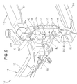
- the left and right rear walls 22b, 22b have left and right fixing parts 51, 51 capable of fixing thereto a component 52 other than the vehicle body 11 in vicinities of left and right joint sections at which the rear ends (rear joint parts 43, 43) of the left and right stays 40, 40 are joined to the left and right rear walls 22b, 22b, respectively.
- the component 52 is fixed only to the right fixing part 51, for example.
- the component 52 may be heavy. Namely, the rear ends of the left and right stays 40, 40 are joined to the left and right rear walls 22b, 22b, more specifically, to the fixing parts 51, 51 for fixing thereto the heavy component 52, and the front ends of the left and right stays 40, 40 are joined to the left and right front walls 22a, 22a and the bumper 14.
- the rigidity of the fixing parts 51, 51 for fixing thereto the heavy component 52 can be increased. Further, distortion of the front bulkhead 13 caused by an external force can be efficiently suppressed, leading to efficient reduction of vibration of the front bulkhead 13 during traveling of the vehicle 10.
- the component 52 is, for example, a washer tank for storing washer liquid to be injected toward a front windshield (not shown) of the vehicle 10, and is relatively heavy.
- the component 52 other than the vehicle body is appropriately called the "vehicular washer tank 52".
- the vehicular washer tank 52 Since it is desirable that the vehicular washer tank 52 be arranged near a washer nozzle (not shown), the vehicular washer tank 52 is fixed to an upper part of the front bulkhead 13 via a bolt 53.
- the part of the front bulkhead 13 to which the vehicular washer tank 52 is fixed is reinforced by the stay 40, whereby distortion of the front bulkhead 13 can be efficiently suppressed, leading to efficient reduction of vibration of the front bulkhead 13.
- the structure for the vehicle body front part of the present invention is well suited for use in vehicles such as passenger vehicles in which a vehicular washer tank is fixed to a front bulkhead mounted on a vehicle body.
Abstract
Description
- The present invention relates to an improvement in a front bulkhead and peripheral parts thereof in a vehicle body front part of a vehicle such as a passenger vehicle.
- Vehicles, such as passenger vehicles, include a front bulkhead provided in a front part of a vehicle body. A bumper is arranged in front of the front bulkhead. One of such vehicle body front part structure is disclosed, for example, in
Patent Document 1. - The vehicle body front part structure disclosed in
Patent Document 1 includes left and right front side frames located in the front part of the vehicle body and extending in a longitudinal direction of the vehicle body, and a front bulkhead mounted between front ends of the left and right front side frames. The front bulkhead is a frame-like component having a substantially rectangular shape in a front view, and includes a bulkhead lower member extending in a vehicle width direction, left and right bulkhead side members extending upward from opposite ends of the bulkhead lower member, and a bulkhead upper member extending between upper ends of the left and right bulkhead side members. - The left and right bulkhead side members are each formed to have a substantially U-shaped cross section, in a plan view, opened outward in the vehicle width direction. More specifically, the left and right bulkhead side members have, respectively, left and right front walls facing toward the front of the vehicle body, left and right rear walls located rearwardly of the left and right front walls at a distance therefrom, and left and right inner walls connecting the left and right front walls and the left and right rear walls.
- However, since the left and right bulkhead side members have such a cross-sectional shape opened outward in the vehicle width direction as described above, there is a limit to the extent to which the rigidity of the left and right bulkhead side members can be increased. In order to reduce vibration of the vehicle body during traveling of the vehicle, it is necessary to increase the rigidities of the front bulkhead and its peripheral parts in the vehicle body front part. If the left and right bulkhead side members are each formed to have a closed cross section to increase the rigidity of the front bulkhead, the weight of the vehicle body would be increased. Thus, there is a room for further improvement in this respect.
- Patent Document 1: Japanese Patent Application Laid-Open Publication No.
2013-032038 - It is therefore an object of the present invention to provide an improved technique for increasing rigidity of a front part of a vehicle body by increasing rigidities of a front bulkhead and its peripheral parts in the vehicle body, while suppressing an undesirable increase in weight of the vehicle body.
- According to one preferred form of the invention, there is provided a vehicle body front part structure including left and right front side frames located in a front part of a vehicle body and extending in a longitudinal direction of the vehicle body, a front bulkhead mounted between front ends of the left and right front side frames, and a bumper arranged in front of the front bulkhead, characterized in that: the front bulkhead includes left and right bulkhead side members extending vertically to constitute left and right side parts of the front bulkhead; the left and right bulkhead side members have, at least, left and right front walls facing toward the front of the vehicle body, and left and right rear walls located rearwardly of the left and right front walls, respectively, at a distance therefrom; the bumper overlaps front surfaces of the left and right front walls; the left and right bulkhead side members are provided with left and right stays extending between the left and right front walls and the left and right rear walls, respectively; front ends of the left and right stays, the left and right front walls, and the bumper are joined together; and rear ends of the left and right stays are joined to the left and right rear walls, respectively.
- It is preferable that the bumper is composed of left and right bumper brackets and a bumper beam bridged between the left and right bumper brackets, and that the left and right bumper brackets are joined to the front ends of the left and right stays, respectively, with the left and right front walls interposed therebetween.
- Preferably, inner ends in a vehicle width direction of the left and right front walls and inner ends in the vehicle width direction of the left and right rear walls are formed integrally by left and right inner walls, respectively, so that the left and right bulkhead side members have substantially U-shaped cross sections in a plan view opened outward in the vehicle width direction, and preferably, the left and right stays are joined not only to the left and right front walls and the left and right rear walls, but also to the left and right inner walls.
- It is preferable that the left and right stays each have a front joint part formed to be joined to a corresponding one of the left and right front walls, a side joint part formed to be joined to a corresponding one of the left and right inner walls, and a corner part formed in a curved shape in a plan view to connect the front joint part and the side joint part.
- Preferably, the left and right stays have left and right beads, respectively, extending in the longitudinal direction of the vehicle body.
- It is preferable that the bumper is joined to the left and right front walls at least at upper joint sections and lower joint sections, the bumper, the left and right front walls, and the front ends of the left and right stays are joined together at the upper joint sections, and that the left and right rear walls have left and right fixing parts capable of fixing thereto a component other than the vehicle body in vicinities of left and right rear joint sections at which the rear ends of the left and right stays are joined to the left and right rear walls, respectively.
- Preferably, the component is a vehicular washer tank.
- In the invention, the left and right bulkhead side members are provided with the left and right stays extending between the left and right front walls and the left and right rear walls located rearwardly of the left and right front walls, respectively, at a distance therefrom, and the left and right stays are joined to the left and right front walls and the left and right rear walls, respectively. It is thereby possible to increase the rigidity of the left and right bulkhead side members, and to suppress distortion of the left and right bulkhead side members caused by an external force. Thus, only by adding the left and right stays, the left and right bulkhead side members can have increased rigidity with such a simple configuration, while suppressing an undesirable increase in weight of the vehicle body.
- Further, the bumper arranged to overlap the front surfaces of the left and right front walls, the left and right front walls, and the front ends of the left and right stays are joined together, respectively. Joint sections between the front ends of the left and right stays and the left and right front walls are located at the same positions as those of the joint sections between the bumper and the left and right front walls. The entire rigidity of the left and right bulkhead side members connected by the bumper can therefore be increased. As a result, the rigidities of the entire front bulkhead and its peripheral parts of the vehicle body can be increased, whereby the rigidity of the front part of the vehicle body can also be increased, and distortion thereof caused by an external force can be suppressed, leading to reduction of vibration of the vehicle body during traveling of the vehicle.
- In the invention, the bumper is formed of separate parts, the left and right bumper brackets to be joined to the left and right front walls and the bumper beam as an impact cushioning member. The bumper beam is bridged between the left and right bumper brackets. The left and right bumper brackets are joined to the front ends of the left and right stays, respectively, with the left and right front walls interposed therebetween, thereby increasing the rigidity of the left and right bulkhead side members. As a result, the rigidity of the front bulkhead can be increased. Further, only the left and right bumper brackets as relatively small members of the bumper have to be joined to the front ends of the left and right stays, respectively, with the left and right front walls interposed therebetween. Therefore, the joining operation can be easily performed, and the manufacturing cost can thus be reduced. In addition, since the bumper is thus formed of separate parts, the left and right bumper brackets and the bumper beam, the bumper beam can be easily replaced when the bumper beam is broken by an impact.
- In the invention, the left and right bulkhead side members are formed to have substantially U-shaped cross sections in the plan view opened outward in the vehicle width direction. The left and right stays are joined not only to the left and right front walls and the left and right rear walls of the left and right bulkhead side members, but also to the left and right inner walls, respectively. In this manner, even though the left and right bulkhead side members are formed to have the substantially U-shaped cross sections, the left and right bulkhead side members are sufficiently reinforced by the left and right stays, whereby the rigidity thereof can be sufficiently secured. As a result, the rigidity of the front part of the vehicle body can be further increased, and distortion thereof caused by an external force can be further suppressed, leading to further reduction of vibration of the vehicle body during traveling of the vehicle.
- In the invention, the left and right stays each have the front joint part formed to be joined to the corresponding one of the left and right front walls, the side joint part formed to be joined to the corresponding one of the left and right inner walls, and the corner part formed in the curved shape in the plan view to connect the front joint part and the side joint part. With the corner part having the curved shape in the plan view, the front joint part and the side joint part are thus connected and integrated with each other to thereby complement each other. Further, since the corner part has the curved shape, stress concentration can be suppressed. It is required that the left and right bulkhead side members, particularly, the left and right front walls have high rigidity because the heavy bumper is joined thereto. In this respect, the rigidity of the front joint parts joined to the front walls can be complemented by the side joint parts. Since the rigidity of the left and right stays is thus increased, the left and right stays can reinforce the left and right bulkhead side members more firmly. Thus, the rigidity of the front part of the vehicle body can be further increased, and distortion thereof caused by an external force can be further suppressed, leading to further reduction of vibration of the vehicle body during traveling of the vehicle.
- In the invention, the left and right stays have the left and right beads, respectively, extending in the longitudinal direction of the vehicle body. Thereby, thin and long convex parts (reverse side parts of the beads) extending in the longitudinal direction of the vehicle body are formed on the left and right stays. With the convex parts for reinforcement, the left and right stays have increased rigidity. Thus, even when a large force is applied to the left and right stays from the front bulkhead, the applied force can be received by the left and right stays. That is, the entire rigidity of the left and right bulkhead side members can thereby be increased. As a result, it is possible to suppress distortion of the front bulkhead caused by an external force, and further, to reduce vibration of the front bulkhead during traveling of the vehicle.
- In the invention, the bumper is joined to the left and right front walls at least at the upper joint sections and the lower joint sections. The bumper, the left and right front walls, and the front ends of the left and right stays are joined together at the upper joint sections. The rear ends of the left and right stays are joined to the left and right rear walls, respectively, at positions rearward of the upper joint sections. It is possible to fix the component other than the vehicle body to the left and right rear walls in the vicinities of the left and right joint sections at which the rear ends of the left and right stays are joined to the left and right rear walls. The component may be heavy. Namely, the rear ends of the left and right stays are joined to the left and right rear walls, more specifically, to the fixing parts for fixing thereto the heavy component, and the front ends of the left and right stays are joined to the left and right front walls and the bumper. As a result, the rigidity of the fixing parts for fixing thereto the heavy component can be increased. Further, distortion of the front bulkhead caused by an external force can be efficiently suppressed, leading to efficient reduction of vibration of the front bulkhead during traveling of the vehicle.
- In the invention, the component is the washer tank for storing washer liquid to be injected toward a front windshield, and is relatively heavy. Since it is desirable that the washer tank be arranged near a washer nozzle, the washer tank is fixed to an upper part of the front bulkhead. The part of the front bulkhead to which the washer tank is fixed is reinforced by a corresponding one of the stays, whereby distortion of the front bulkhead can be efficiently suppressed, leading to efficient reduction of vibration of the front bulkhead.
-
-
Fig. 1 is a perspective view of a front part of a vehicle body according to the present invention as viewed from left front side; -
Fig. 2 is a perspective view of the front part of the vehicle body shown inFig. 1 with a bumper beam being mounted as viewed from left front side; -
Fig. 3 is an exploded view showing a relationship between a left bulkhead side member and a bumper shown inFig. 2 ; -
Fig. 4 is a front view of a left bumper bracket joined to a front wall of the left bulkhead side member shown inFig. 3 ; -
Fig. 5 is a side view showing how the bumper and a left stay are joined to the left bulkhead side member shown inFig. 2 as viewed from outside in a vehicle width direction; -
Fig. 6 is a cross-sectional view taken along line 6 - 6 ofFig. 5 ; -
Fig. 7 is a perspective view of the left stay shown inFig. 5 ; -
Fig. 8 is a cross-sectional view taken along line 8 - 8 ofFig. 7 ; and -
Fig. 9 is a perspective view showing how a washer tank is fixed to a right bulkhead side member shown inFig. 1 as viewed from right front side. - A certain preferred embodiment of the present invention will be described in detail below with reference to the accompanying drawings.
- In the following will be described a vehicle body front part structure according to the embodiment with reference to the drawings.
- As shown in
Figs. 1 and2 , avehicle 10, such as a passenger vehicle, includes avehicle body 11, which is a monocoque body formed to be substantially bilaterally symmetrical with respect to a centerline CL extending in a front-and-rear or longitudinal direction of the vehicle body and passing through a vehicle width center of thevehicle 10. - The
vehicle body 11 includes left and right front-side frames or front side frames 12, 12 located in a front or front part of thevehicle body 11 and extending in the longitudinal direction of the vehicle body, afront bulkhead 13 mounted between front ends of the left and right front side frames 12, 12, and a bumper 14 (Fig. 2 ) arranged in front of thefront bulkhead 13. - The left and right front side frames 12, 12 are each formed to have a substantially U-shaped cross section, in a front view, opened outward in a vehicle width direction, or have a substantially rectangular cross section in the front view.
- The
front bulkhead 13 is a frame-like component having a substantially rectangular shape in a front view, and includes a bulkheadlower member 21 extending in the vehicle width direction, left and right side bulkhead members orbulkhead side members lower member 21, and a bulkheadupper member 23 extending between upper ends of the left and rightbulkhead side members - The left and right
bulkhead side members front bulkhead 13. The left and rightbulkhead side members - The left and right
bulkhead side members bulkhead side members front walls rear walls front walls inner walls front walls rear walls front walls rear walls inner walls bulkhead side members - As shown in
Figs. 1 to 3 , thebumper 14 is a member overlapping front surfaces of the left and rightfront walls right bumper brackets bumper beam 32 bridged between the left andright bumper brackets - More specifically, the left and
right bumper brackets front walls bumper beam 32 is bridged between the left andright bumper brackets bumper beam 32 in the vehicle width direction are arranged to overlap with front surfaces of the left andright bumper brackets right bumper brackets bolts 33. - Since the
bumper 14 is thus formed of separate parts, the left andright bumper brackets bumper beam 32 as an impact cushioning member, thebumper beam 32 can be easily replaced when thebumper beam 32 is broken by an impact. - The
bumper 14, i.e., the left andright bumper brackets front walls joint sections joint sections Figs. 1 ,3 , and4 , the joint sections between the left andright bumper brackets front walls right bumper brackets front walls joint sections right bumper brackets joint sections joint sections - As shown in
Figs. 1 and5 , the left and rightbulkhead side members front walls rear walls bulkhead side member 22 and theleft stay 40 will be detailed. Note that the rightbulkhead side member 22 is bilaterally symmetrical with the leftbulkhead side member 22 and has substantially the same configuration, and thus a description thereof is omitted. Further, theright stay 40 is bilaterally symmetrical with theleft stay 40 and has substantially the same configuration, and thus a description thereof is omitted. - The
left stay 40 is formed in a thin and long shape extending in the longitudinal direction of the vehicle body, and located upward of the leftfront side frame 12. As shown inFigs. 5 and7 , theleft stay 40 is formed by bending a sheet metal, for example. - More specifically, the
left stay 40 has astay base part 41 formed in a substantially plate-like shape with plate surfaces facing upward and downward, a frontjoint part 42 extending upward or downward from a front end of thestay base part 41, a rearjoint part 43 extending upward or downward from a rear end of thestay base part 41, a sidejoint part 44 extending upward or downward from a lateral side end of thestay base part 41, and acorner part 45 extending upward or downward from a corner of thestay base part 41. - For example, the front
joint part 42 constitutes a front flange extending downward from the front end of thestay base part 41. The rearjoint part 43 constitutes a rear flange extending upward from the rear end of thestay base part 41. The sidejoint part 44 constitutes a side flange extending in the same direction as the frontjoint part 42, i.e. downward, from the lateral side end of thestay base part 41. Thecorner part 45 constitutes a front corner of thestay base part 41 connecting the frontjoint part 42 and the sidejoint part 44 and extending in the same direction as the frontjoint part 42, i.e. downward, from the lateral side end of thestay base part 41. Thecorner part 45 is formed in a curved shape (arcuate shape) in a plan view. - Hereinbelow, the front
joint part 42 is appropriately called the "front flange 42". The rearjoint part 43 is appropriately called the "rear flange 43". The sidejoint part 44 is appropriately called the "side flange 44". - The
left stay 40 has a front end (i.e., the front joint part 42) joined to the leftfront wall 22a. Theleft stay 40 has a rear end (i.e., the rear joint part 43) joined to the leftrear wall 22b. Theleft stay 40 has a side end (i.e., the side joint part 44) joined to the leftinner wall 22c. In this manner, theleft stay 40 is joined not only to the leftfront wall 22a and the leftrear wall 22b, but also to the leftinner wall 22c. - As shown in
Figs. 7 and 8 , theleft stay 40 has aleft bead 46 extending in the longitudinal direction of the vehicle body. Thereby, a thin and long convex part 47 (orreverse side part 47 of the bead 46) extending in the longitudinal direction of the vehicle body is formed on theleft stay 40. With theconvex part 47 for reinforcement, theleft stay 40 has increased rigidity. Thus, as shown inFig. 5 , even when a large force is applied to theleft stay 40 from thefront bulkhead 13, the applied force can be received by theleft stay 40. That is, the entire rigidity of the leftbulkhead side member 22 can thereby be increased. As a result, it is possible to suppress distortion of thefront bulkhead 13 caused by an external force, and further, to reduce vibration of thefront bulkhead 13 during traveling of thevehicle 10. Theright stay 40 has the same function. - As shown in
Figs. 1, and 4 to 6 , the front end (front joint part 42) of theleft stay 40, the leftfront wall 22a, and thebumper 14 are joined together. Junction structure of the right stay 40 (Fig. 1 ) is the same as theleft stay 40, and thus a description thereof is omitted. - More specifically, the
left bumper bracket 31 of thebumper 14 is joined to the front end ofleft stay 40 with the leftfront wall 22a interposed therebetween. The junction structure of the right stay 40 (Fig. 1 ) is the same as theleft stay 40, and thus a description thereof is omitted. - Joint sections at which the
bumper 14, the left and rightfront walls joint parts 42, 42) of the left and right stays 40, 40 are respectively joined together are the abovementioned left and right upperjoint sections bumper 14, the left and rightfront walls joint sections joint parts 43, 43) of the left and right stays 40, 40 are joined to the left and rightrear walls joint sections - Summary of the descriptions above is as follows. As shown in
Figs. 1 and2 , the left and rightbulkhead side members front walls rear walls front walls rear walls bulkhead side members bulkhead side members bulkhead side members - Further, the
bumper 14 arranged to overlap the front surfaces of the left and rightfront walls front walls front walls bumper 14 and the left and rightfront walls bulkhead side members bumper 14 can therefore be increased. As a result, the rigidities of the entirefront bulkhead 13 and its peripheral parts of thevehicle body 11 can be increased, whereby the rigidity of the front part of thevehicle body 11 can also be increased, and distortion thereof caused by an external force can be suppressed, leading to reduction of vibration of thevehicle body 11 during traveling of thevehicle 10. - As shown in
Figs. 1 and3 , the left andright bumper brackets front walls bulkhead side members front bulkhead 13 can be increased. Further, only the left andright bumper brackets bumper 14 have to be joined to the front ends of the left and right stays 40, 40, respectively, with the left and rightfront walls - As shown in
Figs. 1 ,5 and6 , the left and right stays 40, 40 are joined not only to the left and rightfront walls rear walls bulkhead side members inner walls bulkhead side members bulkhead side members vehicle body 11 can be further increased, and distortion thereof caused by an external force can be further suppressed, leading to further reduction of vibration of thevehicle body 11 during traveling of thevehicle 10. - As shown in
Figs. 6 and7 , theleft stay 40 has the frontjoint part 42 formed to be joined to the leftfront wall 22a, the sidejoint part 44 formed to be joined to the leftinner wall 22c, and thecorner part 45 formed in the curved shape in the plan view to connect the frontjoint part 42 and the sidejoint part 44. With thecorner part 45 having the curved shape in the plan view, the frontjoint part 42 and the sidejoint part 44 are thus connected and integrated with each other to thereby complement each other. Further, since thecorner part 45 has the curved shape, stress concentration can be suppressed. Theright stay 40 has substantially the same configuration, and thus a description thereof is omitted. - As shown in
Fig. 2 , it is required that the left and rightbulkhead side members front walls heavy bumper 14 is joined thereto. In this respect, the rigidity of the frontjoint parts front walls joint parts bulkhead side members vehicle body 11 can be further increased, and distortion thereof caused by an external force can be further suppressed, leading to further reduction of vibration of thevehicle body 11 during traveling of thevehicle 10. - As shown in
Figs. 3 and9 , the left and rightrear walls parts component 52 other than thevehicle body 11 in vicinities of left and right joint sections at which the rear ends (rearjoint parts 43, 43) of the left and right stays 40, 40 are joined to the left and rightrear walls - As shown in
Fig. 9 , thecomponent 52 is fixed only to theright fixing part 51, for example. Thecomponent 52 may be heavy. Namely, the rear ends of the left and right stays 40, 40 are joined to the left and rightrear walls parts heavy component 52, and the front ends of the left and right stays 40, 40 are joined to the left and rightfront walls bumper 14. As a result, the rigidity of the fixingparts heavy component 52 can be increased. Further, distortion of thefront bulkhead 13 caused by an external force can be efficiently suppressed, leading to efficient reduction of vibration of thefront bulkhead 13 during traveling of thevehicle 10. - The
component 52 is, for example, a washer tank for storing washer liquid to be injected toward a front windshield (not shown) of thevehicle 10, and is relatively heavy. Hereinbelow, thecomponent 52 other than the vehicle body is appropriately called the "vehicular washer tank 52". - Since it is desirable that the
vehicular washer tank 52 be arranged near a washer nozzle (not shown), thevehicular washer tank 52 is fixed to an upper part of thefront bulkhead 13 via abolt 53. The part of thefront bulkhead 13 to which thevehicular washer tank 52 is fixed is reinforced by thestay 40, whereby distortion of thefront bulkhead 13 can be efficiently suppressed, leading to efficient reduction of vibration of thefront bulkhead 13. - The structure for the vehicle body front part of the present invention is well suited for use in vehicles such as passenger vehicles in which a vehicular washer tank is fixed to a front bulkhead mounted on a vehicle body.
- 10 ... vehicle, 11 ... vehicle body, 12 ... front side frame, 13 ... front bulkhead, 14 ... bumper, 22 ... bulkhead side member (side part of the front bulkhead), 22a ... front wall, 22b ... rear wall, 22c ... inner wall, 31 ... bumper bracket, 32 ... bumper beam, 35 ... upper joint section, 36 ... lower joint section, 40 ... stay, 42 ... front end of the stay (front joint part), 43 ... rear end of the stay (rear joint part), 44 ... side joint part, 45 ...
corner part
Claims (7)
- A vehicle body front part structure including left and right front side frames located in a front part of a vehicle body and extending in a longitudinal direction of the vehicle body, a front bulkhead mounted between front ends of the left and right front side frames, and a bumper arranged in front of the front bulkhead, characterized in that:the front bulkhead includes left and right bulkhead side members extending vertically to constitute left and right side parts of the front bulkhead;the left and right bulkhead side members have, at least, left and right front walls facing toward the front of the vehicle body, and left and right rear walls located rearwardly of the left and right front walls, respectively, at a distance therefrom;the bumper overlaps front surfaces of the left and right front walls;the left and right bulkhead side members are provided with left and right stays extending between the left and right front walls and the left and right rear walls, respectively;front ends of the left and right stays, the left and right front walls, and the bumper are joined together; andrear ends of the left and right stays are joined to the left and right rear walls, respectively.
- The vehicle body front part structure of claim 1, wherein the bumper is composed of left and right bumper brackets and a bumper beam bridged between the left and right bumper brackets, and wherein the left and right bumper brackets are joined to the front ends of the left and right stays, respectively, with the left and right front walls interposed therebetween.
- The vehicle body front part structure of claim 1 or 2, wherein inner ends in a vehicle width direction of the left and right front walls and inner ends in the vehicle width direction of the left and right rear walls are formed integrally with left and left and right inner walls, respectively, so that the left and right bulkhead side members have substantially U-shaped cross sections in a plan view opened outward in the vehicle width direction, and wherein the left and right stays are joined not only to the left and right front walls and the left and right rear walls, but also to the left and right inner walls.
- The vehicle body front part structure of claim 3, wherein the left and right stays each have a front joint part formed to be joined to a corresponding one of the left and right front walls, a side joint part formed to be joined to a corresponding one of the left and right inner walls, and a corner part formed in a curved shape in a plan view to connect the front joint part and the side joint part.
- The vehicle body front part structure of claim 1, wherein the left and right stays have left and right beads, respectively, extending in the longitudinal direction of the vehicle body.
- The vehicle body front part structure of claim 1, wherein the bumper is joined to the left and right front walls at least at upper joint sections and lower joint sections, wherein the bumper, the left and right front walls, and the front ends of the left and right stays are joined together at the upper joint sections, and wherein the left and right rear walls have left and right fixing parts capable of fixing thereto a component other than the vehicle body in vicinities of left and right rear joint sections at which the rear ends of the left and right stays are joined to the left and right rear walls, respectively.
- The vehicle body front part structure of claim 6, wherein the component is a vehicular washer tank.
Applications Claiming Priority (2)
| Application Number | Priority Date | Filing Date | Title |
|---|---|---|---|
| JP2013178859 | 2013-08-30 | ||
| PCT/JP2014/064722 WO2015029531A1 (en) | 2013-08-30 | 2014-06-03 | Structure for front of vehicle body |
Publications (3)
| Publication Number | Publication Date |
|---|---|
| EP3040255A1 true EP3040255A1 (en) | 2016-07-06 |
| EP3040255A4 EP3040255A4 (en) | 2017-06-21 |
| EP3040255B1 EP3040255B1 (en) | 2018-02-28 |
Family
ID=52586110
Family Applications (1)
| Application Number | Title | Priority Date | Filing Date |
|---|---|---|---|
| EP14840534.3A Active EP3040255B1 (en) | 2013-08-30 | 2014-06-03 | Structure for front of vehicle body |
Country Status (5)
| Country | Link |
|---|---|
| US (1) | US9493131B2 (en) |
| EP (1) | EP3040255B1 (en) |
| JP (1) | JP6010230B2 (en) |
| CN (1) | CN105492301B (en) |
| WO (1) | WO2015029531A1 (en) |
Families Citing this family (2)
| Publication number | Priority date | Publication date | Assignee | Title |
|---|---|---|---|---|
| JP6265342B2 (en) | 2015-09-29 | 2018-01-24 | 本田技研工業株式会社 | Body front structure |
| CN105539335A (en) * | 2015-12-25 | 2016-05-04 | 苏州奥杰汽车技术股份有限公司 | Frame with energy absorption structure |
Family Cites Families (16)
| Publication number | Priority date | Publication date | Assignee | Title |
|---|---|---|---|---|
| JP4762444B2 (en) * | 2001-06-15 | 2011-08-31 | 富士重工業株式会社 | Vehicle front-end structure |
| FR2879155B1 (en) * | 2004-12-09 | 2008-06-06 | Valeo Thermique Moteur Sas | FRONT FACE SUPPORT FOR A MOTOR VEHICLE COMPRISING AN INTEGRATED CAVITY. |
| DE102006009290B4 (en) * | 2006-03-01 | 2011-06-16 | Audi Ag | Support structure for a front end of a motor vehicle |
| JP4233053B2 (en) * | 2006-04-27 | 2009-03-04 | 本田技研工業株式会社 | Body front structure |
| JP4853197B2 (en) * | 2006-09-19 | 2012-01-11 | マツダ株式会社 | Vehicle front structure |
| JP4601604B2 (en) * | 2006-12-27 | 2010-12-22 | 三菱自動車工業株式会社 | Body structure |
| JP2010149601A (en) * | 2008-12-24 | 2010-07-08 | Toyota Motor Corp | Radiator support structure |
| US8764104B2 (en) * | 2010-09-14 | 2014-07-01 | Honda Motor Co., Ltd. | Structure of front section of vehicle body |
| CN103347773B (en) * | 2011-01-26 | 2016-01-06 | 本田技研工业株式会社 | Car body fore part arrangement |
| JP2012192837A (en) * | 2011-03-16 | 2012-10-11 | Daihatsu Motor Co Ltd | Front vehicle body structure of automobile |
| JP5767842B2 (en) * | 2011-03-31 | 2015-08-19 | 本田技研工業株式会社 | Body front structure |
| JP5449271B2 (en) | 2011-07-30 | 2014-03-19 | 本田技研工業株式会社 | Vehicle front body |
| JP5790333B2 (en) * | 2011-08-31 | 2015-10-07 | マツダ株式会社 | Vehicle body structure |
| JP5629411B2 (en) * | 2011-09-06 | 2014-11-19 | 豊田鉄工株式会社 | Vehicle cooling component support device |
| FR2996503B1 (en) * | 2012-10-10 | 2016-11-04 | Renault Sa | ARRANGEMENT OF A FRONT PART OF A MOTOR VEHICLE |
| JP2015168364A (en) * | 2014-03-07 | 2015-09-28 | トヨタ自動車株式会社 | Front structure of vehicle body |
-
2014
- 2014-06-03 WO PCT/JP2014/064722 patent/WO2015029531A1/en active Application Filing
- 2014-06-03 JP JP2015534035A patent/JP6010230B2/en active Active
- 2014-06-03 US US14/911,375 patent/US9493131B2/en active Active
- 2014-06-03 EP EP14840534.3A patent/EP3040255B1/en active Active
- 2014-06-03 CN CN201480048112.2A patent/CN105492301B/en active Active
Also Published As
| Publication number | Publication date |
|---|---|
| WO2015029531A1 (en) | 2015-03-05 |
| US20160193978A1 (en) | 2016-07-07 |
| US9493131B2 (en) | 2016-11-15 |
| EP3040255B1 (en) | 2018-02-28 |
| JPWO2015029531A1 (en) | 2017-03-02 |
| JP6010230B2 (en) | 2016-10-19 |
| EP3040255A4 (en) | 2017-06-21 |
| CN105492301A (en) | 2016-04-13 |
| CN105492301B (en) | 2017-10-24 |
Similar Documents
| Publication | Publication Date | Title |
|---|---|---|
| US9914484B2 (en) | Vehicle body front structure | |
| US8764104B2 (en) | Structure of front section of vehicle body | |
| US9988089B2 (en) | Vehicle body front structure | |
| US10486751B2 (en) | Side vehicle body structure of vehicle | |
| US10112651B2 (en) | Vehicle body front structure | |
| US11524726B2 (en) | Body structure for automobiles | |
| JP2013212757A (en) | Vehicle body front structure of vehicle | |
| JP2006327284A (en) | Roof structure of automobile | |
| US9248863B2 (en) | Vehicle body superstructure | |
| JP2019006311A (en) | Vehicle-body front part structure | |
| JP6574947B2 (en) | Lower body structure | |
| JP5966280B2 (en) | Strut tower reinforcement structure for vehicles | |
| EP2412612A1 (en) | Side sill structure for automobile | |
| US10322753B2 (en) | Vehicle body front structure | |
| US9493131B2 (en) | Structure for front of vehicle body | |
| CN108349547B (en) | Front body structure of automobile | |
| CN109204554B (en) | Vehicle body rear structure | |
| JP2020147067A (en) | Vehicle front section structure | |
| JP4729015B2 (en) | Connecting member for body frame | |
| KR101673341B1 (en) | Structure for connecting vehicle body member | |
| JP2015105004A (en) | Structure of underrun protector | |
| JP2021142764A (en) | Body structure of automobile | |
| JP2011201331A (en) | Front body structure of automobile | |
| JP2016104625A (en) | Vehicle body front structure for vehicle | |
| JP2017087865A (en) | Vehicle side part body structure |
Legal Events
| Date | Code | Title | Description |
|---|---|---|---|
| PUAI | Public reference made under article 153(3) epc to a published international application that has entered the european phase |
Free format text: ORIGINAL CODE: 0009012 |
|
| 17P | Request for examination filed |
Effective date: 20160219 |
|
| AK | Designated contracting states |
Kind code of ref document: A1 Designated state(s): AL AT BE BG CH CY CZ DE DK EE ES FI FR GB GR HR HU IE IS IT LI LT LU LV MC MK MT NL NO PL PT RO RS SE SI SK SM TR |
|
| AX | Request for extension of the european patent |
Extension state: BA ME |
|
| DAX | Request for extension of the european patent (deleted) | ||
| A4 | Supplementary search report drawn up and despatched |
Effective date: 20170523 |
|
| RIC1 | Information provided on ipc code assigned before grant |
Ipc: B62D 25/08 20060101AFI20170517BHEP Ipc: B60R 19/24 20060101ALI20170517BHEP |
|
| GRAP | Despatch of communication of intention to grant a patent |
Free format text: ORIGINAL CODE: EPIDOSNIGR1 |
|
| INTG | Intention to grant announced |
Effective date: 20170920 |
|
| GRAS | Grant fee paid |
Free format text: ORIGINAL CODE: EPIDOSNIGR3 |
|
| GRAA | (expected) grant |
Free format text: ORIGINAL CODE: 0009210 |
|
| AK | Designated contracting states |
Kind code of ref document: B1 Designated state(s): AL AT BE BG CH CY CZ DE DK EE ES FI FR GB GR HR HU IE IS IT LI LT LU LV MC MK MT NL NO PL PT RO RS SE SI SK SM TR |
|
| REG | Reference to a national code |
Ref country code: GB Ref legal event code: FG4D Ref country code: CH Ref legal event code: EP |
|
| REG | Reference to a national code |
Ref country code: AT Ref legal event code: REF Ref document number: 973784 Country of ref document: AT Kind code of ref document: T Effective date: 20180315 |
|
| REG | Reference to a national code |
Ref country code: IE Ref legal event code: FG4D |
|
| REG | Reference to a national code |
Ref country code: DE Ref legal event code: R096 Ref document number: 602014021797 Country of ref document: DE |
|
| REG | Reference to a national code |
Ref country code: NL Ref legal event code: MP Effective date: 20180228 |
|
| REG | Reference to a national code |
Ref country code: LT Ref legal event code: MG4D |
|
| REG | Reference to a national code |
Ref country code: AT Ref legal event code: MK05 Ref document number: 973784 Country of ref document: AT Kind code of ref document: T Effective date: 20180228 |
|
| PG25 | Lapsed in a contracting state [announced via postgrant information from national office to epo] |
Ref country code: NO Free format text: LAPSE BECAUSE OF FAILURE TO SUBMIT A TRANSLATION OF THE DESCRIPTION OR TO PAY THE FEE WITHIN THE PRESCRIBED TIME-LIMIT Effective date: 20180528 Ref country code: FI Free format text: LAPSE BECAUSE OF FAILURE TO SUBMIT A TRANSLATION OF THE DESCRIPTION OR TO PAY THE FEE WITHIN THE PRESCRIBED TIME-LIMIT Effective date: 20180228 Ref country code: HR Free format text: LAPSE BECAUSE OF FAILURE TO SUBMIT A TRANSLATION OF THE DESCRIPTION OR TO PAY THE FEE WITHIN THE PRESCRIBED TIME-LIMIT Effective date: 20180228 Ref country code: ES Free format text: LAPSE BECAUSE OF FAILURE TO SUBMIT A TRANSLATION OF THE DESCRIPTION OR TO PAY THE FEE WITHIN THE PRESCRIBED TIME-LIMIT Effective date: 20180228 Ref country code: NL Free format text: LAPSE BECAUSE OF FAILURE TO SUBMIT A TRANSLATION OF THE DESCRIPTION OR TO PAY THE FEE WITHIN THE PRESCRIBED TIME-LIMIT Effective date: 20180228 Ref country code: LT Free format text: LAPSE BECAUSE OF FAILURE TO SUBMIT A TRANSLATION OF THE DESCRIPTION OR TO PAY THE FEE WITHIN THE PRESCRIBED TIME-LIMIT Effective date: 20180228 Ref country code: CY Free format text: LAPSE BECAUSE OF FAILURE TO SUBMIT A TRANSLATION OF THE DESCRIPTION OR TO PAY THE FEE WITHIN THE PRESCRIBED TIME-LIMIT Effective date: 20180228 |
|
| PG25 | Lapsed in a contracting state [announced via postgrant information from national office to epo] |
Ref country code: RS Free format text: LAPSE BECAUSE OF FAILURE TO SUBMIT A TRANSLATION OF THE DESCRIPTION OR TO PAY THE FEE WITHIN THE PRESCRIBED TIME-LIMIT Effective date: 20180228 Ref country code: GR Free format text: LAPSE BECAUSE OF FAILURE TO SUBMIT A TRANSLATION OF THE DESCRIPTION OR TO PAY THE FEE WITHIN THE PRESCRIBED TIME-LIMIT Effective date: 20180529 Ref country code: AT Free format text: LAPSE BECAUSE OF FAILURE TO SUBMIT A TRANSLATION OF THE DESCRIPTION OR TO PAY THE FEE WITHIN THE PRESCRIBED TIME-LIMIT Effective date: 20180228 Ref country code: SE Free format text: LAPSE BECAUSE OF FAILURE TO SUBMIT A TRANSLATION OF THE DESCRIPTION OR TO PAY THE FEE WITHIN THE PRESCRIBED TIME-LIMIT Effective date: 20180228 Ref country code: LV Free format text: LAPSE BECAUSE OF FAILURE TO SUBMIT A TRANSLATION OF THE DESCRIPTION OR TO PAY THE FEE WITHIN THE PRESCRIBED TIME-LIMIT Effective date: 20180228 Ref country code: BG Free format text: LAPSE BECAUSE OF FAILURE TO SUBMIT A TRANSLATION OF THE DESCRIPTION OR TO PAY THE FEE WITHIN THE PRESCRIBED TIME-LIMIT Effective date: 20180528 |
|
| PG25 | Lapsed in a contracting state [announced via postgrant information from national office to epo] |
Ref country code: AL Free format text: LAPSE BECAUSE OF FAILURE TO SUBMIT A TRANSLATION OF THE DESCRIPTION OR TO PAY THE FEE WITHIN THE PRESCRIBED TIME-LIMIT Effective date: 20180228 Ref country code: EE Free format text: LAPSE BECAUSE OF FAILURE TO SUBMIT A TRANSLATION OF THE DESCRIPTION OR TO PAY THE FEE WITHIN THE PRESCRIBED TIME-LIMIT Effective date: 20180228 Ref country code: RO Free format text: LAPSE BECAUSE OF FAILURE TO SUBMIT A TRANSLATION OF THE DESCRIPTION OR TO PAY THE FEE WITHIN THE PRESCRIBED TIME-LIMIT Effective date: 20180228 Ref country code: IT Free format text: LAPSE BECAUSE OF FAILURE TO SUBMIT A TRANSLATION OF THE DESCRIPTION OR TO PAY THE FEE WITHIN THE PRESCRIBED TIME-LIMIT Effective date: 20180228 Ref country code: PL Free format text: LAPSE BECAUSE OF FAILURE TO SUBMIT A TRANSLATION OF THE DESCRIPTION OR TO PAY THE FEE WITHIN THE PRESCRIBED TIME-LIMIT Effective date: 20180228 |
|
| REG | Reference to a national code |
Ref country code: DE Ref legal event code: R097 Ref document number: 602014021797 Country of ref document: DE |
|
| PG25 | Lapsed in a contracting state [announced via postgrant information from national office to epo] |
Ref country code: CZ Free format text: LAPSE BECAUSE OF FAILURE TO SUBMIT A TRANSLATION OF THE DESCRIPTION OR TO PAY THE FEE WITHIN THE PRESCRIBED TIME-LIMIT Effective date: 20180228 Ref country code: SK Free format text: LAPSE BECAUSE OF FAILURE TO SUBMIT A TRANSLATION OF THE DESCRIPTION OR TO PAY THE FEE WITHIN THE PRESCRIBED TIME-LIMIT Effective date: 20180228 Ref country code: DK Free format text: LAPSE BECAUSE OF FAILURE TO SUBMIT A TRANSLATION OF THE DESCRIPTION OR TO PAY THE FEE WITHIN THE PRESCRIBED TIME-LIMIT Effective date: 20180228 Ref country code: SM Free format text: LAPSE BECAUSE OF FAILURE TO SUBMIT A TRANSLATION OF THE DESCRIPTION OR TO PAY THE FEE WITHIN THE PRESCRIBED TIME-LIMIT Effective date: 20180228 |
|
| PLBE | No opposition filed within time limit |
Free format text: ORIGINAL CODE: 0009261 |
|
| STAA | Information on the status of an ep patent application or granted ep patent |
Free format text: STATUS: NO OPPOSITION FILED WITHIN TIME LIMIT |
|
| REG | Reference to a national code |
Ref country code: CH Ref legal event code: PL |
|
| 26N | No opposition filed |
Effective date: 20181129 |
|
| PG25 | Lapsed in a contracting state [announced via postgrant information from national office to epo] |
Ref country code: SI Free format text: LAPSE BECAUSE OF FAILURE TO SUBMIT A TRANSLATION OF THE DESCRIPTION OR TO PAY THE FEE WITHIN THE PRESCRIBED TIME-LIMIT Effective date: 20180228 |
|
| REG | Reference to a national code |
Ref country code: BE Ref legal event code: MM Effective date: 20180630 |
|
| REG | Reference to a national code |
Ref country code: IE Ref legal event code: MM4A |
|
| PG25 | Lapsed in a contracting state [announced via postgrant information from national office to epo] |
Ref country code: LU Free format text: LAPSE BECAUSE OF NON-PAYMENT OF DUE FEES Effective date: 20180603 Ref country code: MC Free format text: LAPSE BECAUSE OF FAILURE TO SUBMIT A TRANSLATION OF THE DESCRIPTION OR TO PAY THE FEE WITHIN THE PRESCRIBED TIME-LIMIT Effective date: 20180228 |
|
| PG25 | Lapsed in a contracting state [announced via postgrant information from national office to epo] |
Ref country code: FR Free format text: LAPSE BECAUSE OF NON-PAYMENT OF DUE FEES Effective date: 20180630 Ref country code: IE Free format text: LAPSE BECAUSE OF NON-PAYMENT OF DUE FEES Effective date: 20180603 Ref country code: LI Free format text: LAPSE BECAUSE OF NON-PAYMENT OF DUE FEES Effective date: 20180630 Ref country code: CH Free format text: LAPSE BECAUSE OF NON-PAYMENT OF DUE FEES Effective date: 20180630 |
|
| PG25 | Lapsed in a contracting state [announced via postgrant information from national office to epo] |
Ref country code: BE Free format text: LAPSE BECAUSE OF NON-PAYMENT OF DUE FEES Effective date: 20180630 |
|
| PG25 | Lapsed in a contracting state [announced via postgrant information from national office to epo] |
Ref country code: MT Free format text: LAPSE BECAUSE OF NON-PAYMENT OF DUE FEES Effective date: 20180603 |
|
| PG25 | Lapsed in a contracting state [announced via postgrant information from national office to epo] |
Ref country code: TR Free format text: LAPSE BECAUSE OF FAILURE TO SUBMIT A TRANSLATION OF THE DESCRIPTION OR TO PAY THE FEE WITHIN THE PRESCRIBED TIME-LIMIT Effective date: 20180228 |
|
| PG25 | Lapsed in a contracting state [announced via postgrant information from national office to epo] |
Ref country code: PT Free format text: LAPSE BECAUSE OF FAILURE TO SUBMIT A TRANSLATION OF THE DESCRIPTION OR TO PAY THE FEE WITHIN THE PRESCRIBED TIME-LIMIT Effective date: 20180228 |
|
| PG25 | Lapsed in a contracting state [announced via postgrant information from national office to epo] |
Ref country code: MK Free format text: LAPSE BECAUSE OF NON-PAYMENT OF DUE FEES Effective date: 20180228 Ref country code: HU Free format text: LAPSE BECAUSE OF FAILURE TO SUBMIT A TRANSLATION OF THE DESCRIPTION OR TO PAY THE FEE WITHIN THE PRESCRIBED TIME-LIMIT; INVALID AB INITIO Effective date: 20140603 |
|
| PG25 | Lapsed in a contracting state [announced via postgrant information from national office to epo] |
Ref country code: IS Free format text: LAPSE BECAUSE OF FAILURE TO SUBMIT A TRANSLATION OF THE DESCRIPTION OR TO PAY THE FEE WITHIN THE PRESCRIBED TIME-LIMIT Effective date: 20180628 |
|
| REG | Reference to a national code |
Ref country code: DE Ref legal event code: R084 Ref document number: 602014021797 Country of ref document: DE |
|
| REG | Reference to a national code |
Ref country code: GB Ref legal event code: 746 Effective date: 20210901 |
|
| PGFP | Annual fee paid to national office [announced via postgrant information from national office to epo] |
Ref country code: GB Payment date: 20220414 Year of fee payment: 9 |
|
| PGFP | Annual fee paid to national office [announced via postgrant information from national office to epo] |
Ref country code: DE Payment date: 20230412 Year of fee payment: 10 |
|
| GBPC | Gb: european patent ceased through non-payment of renewal fee |
Effective date: 20230603 |
|
| PG25 | Lapsed in a contracting state [announced via postgrant information from national office to epo] |
Ref country code: GB Free format text: LAPSE BECAUSE OF NON-PAYMENT OF DUE FEES Effective date: 20230603 |