EP3039660B1 - Method for detecting falls and a fall detection system - Google Patents
Method for detecting falls and a fall detection system Download PDFInfo
- Publication number
- EP3039660B1 EP3039660B1 EP14749823.2A EP14749823A EP3039660B1 EP 3039660 B1 EP3039660 B1 EP 3039660B1 EP 14749823 A EP14749823 A EP 14749823A EP 3039660 B1 EP3039660 B1 EP 3039660B1
- Authority
- EP
- European Patent Office
- Prior art keywords
- user
- fall
- detection system
- measurements
- proximity
- Prior art date
- Legal status (The legal status is an assumption and is not a legal conclusion. Google has not performed a legal analysis and makes no representation as to the accuracy of the status listed.)
- Active
Links
- 238000001514 detection method Methods 0.000 title claims description 175
- 238000000034 method Methods 0.000 title claims description 49
- 238000005259 measurement Methods 0.000 claims description 97
- 238000012545 processing Methods 0.000 claims description 74
- 230000008859 change Effects 0.000 claims description 27
- 230000008569 process Effects 0.000 claims description 19
- 230000003213 activating effect Effects 0.000 claims description 10
- 238000004590 computer program Methods 0.000 claims description 3
- 210000000707 wrist Anatomy 0.000 description 33
- 238000004422 calculation algorithm Methods 0.000 description 20
- 238000002604 ultrasonography Methods 0.000 description 10
- 238000004458 analytical method Methods 0.000 description 7
- 238000004891 communication Methods 0.000 description 7
- 230000005484 gravity Effects 0.000 description 6
- 230000001965 increasing effect Effects 0.000 description 5
- 230000001133 acceleration Effects 0.000 description 4
- 230000000694 effects Effects 0.000 description 4
- 230000006870 function Effects 0.000 description 4
- 230000001960 triggered effect Effects 0.000 description 4
- 238000003491 array Methods 0.000 description 3
- 230000004044 response Effects 0.000 description 3
- 238000013459 approach Methods 0.000 description 2
- 230000008901 benefit Effects 0.000 description 2
- 238000006073 displacement reaction Methods 0.000 description 2
- 238000005516 engineering process Methods 0.000 description 2
- 230000009467 reduction Effects 0.000 description 2
- 241000699670 Mus sp. Species 0.000 description 1
- 208000003443 Unconsciousness Diseases 0.000 description 1
- 239000011358 absorbing material Substances 0.000 description 1
- 230000009286 beneficial effect Effects 0.000 description 1
- 230000005540 biological transmission Effects 0.000 description 1
- 238000004364 calculation method Methods 0.000 description 1
- 238000012790 confirmation Methods 0.000 description 1
- 238000007796 conventional method Methods 0.000 description 1
- 238000012937 correction Methods 0.000 description 1
- 230000008878 coupling Effects 0.000 description 1
- 238000010168 coupling process Methods 0.000 description 1
- 238000005859 coupling reaction Methods 0.000 description 1
- 230000006378 damage Effects 0.000 description 1
- 230000001419 dependent effect Effects 0.000 description 1
- 238000010586 diagram Methods 0.000 description 1
- 230000007613 environmental effect Effects 0.000 description 1
- 210000003414 extremity Anatomy 0.000 description 1
- 230000001976 improved effect Effects 0.000 description 1
- 230000001939 inductive effect Effects 0.000 description 1
- 230000000977 initiatory effect Effects 0.000 description 1
- 238000010295 mobile communication Methods 0.000 description 1
- 238000012986 modification Methods 0.000 description 1
- 230000004048 modification Effects 0.000 description 1
- 230000003287 optical effect Effects 0.000 description 1
- 238000007781 pre-processing Methods 0.000 description 1
- 230000035945 sensitivity Effects 0.000 description 1
- 238000012360 testing method Methods 0.000 description 1
Images


Classifications
-
- G—PHYSICS
- G08—SIGNALLING
- G08B—SIGNALLING OR CALLING SYSTEMS; ORDER TELEGRAPHS; ALARM SYSTEMS
- G08B21/00—Alarms responsive to a single specified undesired or abnormal condition and not otherwise provided for
- G08B21/02—Alarms for ensuring the safety of persons
- G08B21/04—Alarms for ensuring the safety of persons responsive to non-activity, e.g. of elderly persons
- G08B21/0438—Sensor means for detecting
- G08B21/0446—Sensor means for detecting worn on the body to detect changes of posture, e.g. a fall, inclination, acceleration, gait
-
- A—HUMAN NECESSITIES
- A61—MEDICAL OR VETERINARY SCIENCE; HYGIENE
- A61B—DIAGNOSIS; SURGERY; IDENTIFICATION
- A61B5/00—Measuring for diagnostic purposes; Identification of persons
- A61B5/103—Detecting, measuring or recording devices for testing the shape, pattern, colour, size or movement of the body or parts thereof, for diagnostic purposes
- A61B5/11—Measuring movement of the entire body or parts thereof, e.g. head or hand tremor, mobility of a limb
- A61B5/1116—Determining posture transitions
- A61B5/1117—Fall detection
-
- A—HUMAN NECESSITIES
- A61—MEDICAL OR VETERINARY SCIENCE; HYGIENE
- A61B—DIAGNOSIS; SURGERY; IDENTIFICATION
- A61B5/00—Measuring for diagnostic purposes; Identification of persons
- A61B5/68—Arrangements of detecting, measuring or recording means, e.g. sensors, in relation to patient
- A61B5/6801—Arrangements of detecting, measuring or recording means, e.g. sensors, in relation to patient specially adapted to be attached to or worn on the body surface
- A61B5/6802—Sensor mounted on worn items
- A61B5/681—Wristwatch-type devices
-
- A—HUMAN NECESSITIES
- A61—MEDICAL OR VETERINARY SCIENCE; HYGIENE
- A61B—DIAGNOSIS; SURGERY; IDENTIFICATION
- A61B5/00—Measuring for diagnostic purposes; Identification of persons
- A61B5/74—Details of notification to user or communication with user or patient ; user input means
- A61B5/746—Alarms related to a physiological condition, e.g. details of setting alarm thresholds or avoiding false alarms
-
- G—PHYSICS
- G08—SIGNALLING
- G08B—SIGNALLING OR CALLING SYSTEMS; ORDER TELEGRAPHS; ALARM SYSTEMS
- G08B21/00—Alarms responsive to a single specified undesired or abnormal condition and not otherwise provided for
- G08B21/02—Alarms for ensuring the safety of persons
- G08B21/04—Alarms for ensuring the safety of persons responsive to non-activity, e.g. of elderly persons
- G08B21/0407—Alarms for ensuring the safety of persons responsive to non-activity, e.g. of elderly persons based on behaviour analysis
- G08B21/043—Alarms for ensuring the safety of persons responsive to non-activity, e.g. of elderly persons based on behaviour analysis detecting an emergency event, e.g. a fall
-
- G—PHYSICS
- G08—SIGNALLING
- G08B—SIGNALLING OR CALLING SYSTEMS; ORDER TELEGRAPHS; ALARM SYSTEMS
- G08B21/00—Alarms responsive to a single specified undesired or abnormal condition and not otherwise provided for
- G08B21/02—Alarms for ensuring the safety of persons
- G08B21/04—Alarms for ensuring the safety of persons responsive to non-activity, e.g. of elderly persons
- G08B21/0438—Sensor means for detecting
- G08B21/0492—Sensor dual technology, i.e. two or more technologies collaborate to extract unsafe condition, e.g. video tracking and RFID tracking
-
- A—HUMAN NECESSITIES
- A61—MEDICAL OR VETERINARY SCIENCE; HYGIENE
- A61B—DIAGNOSIS; SURGERY; IDENTIFICATION
- A61B2560/00—Constructional details of operational features of apparatus; Accessories for medical measuring apparatus
- A61B2560/04—Constructional details of apparatus
-
- A—HUMAN NECESSITIES
- A61—MEDICAL OR VETERINARY SCIENCE; HYGIENE
- A61B—DIAGNOSIS; SURGERY; IDENTIFICATION
- A61B2562/00—Details of sensors; Constructional details of sensor housings or probes; Accessories for sensors
- A61B2562/02—Details of sensors specially adapted for in-vivo measurements
- A61B2562/0219—Inertial sensors, e.g. accelerometers, gyroscopes, tilt switches
-
- A—HUMAN NECESSITIES
- A61—MEDICAL OR VETERINARY SCIENCE; HYGIENE
- A61B—DIAGNOSIS; SURGERY; IDENTIFICATION
- A61B2562/00—Details of sensors; Constructional details of sensor housings or probes; Accessories for sensors
- A61B2562/02—Details of sensors specially adapted for in-vivo measurements
- A61B2562/0247—Pressure sensors
-
- A—HUMAN NECESSITIES
- A61—MEDICAL OR VETERINARY SCIENCE; HYGIENE
- A61B—DIAGNOSIS; SURGERY; IDENTIFICATION
- A61B2562/00—Details of sensors; Constructional details of sensor housings or probes; Accessories for sensors
- A61B2562/02—Details of sensors specially adapted for in-vivo measurements
- A61B2562/0257—Proximity sensors
Definitions
- the invention relates to a method for detecting falls by a user and a fall detection system implementing the same, and in particular relates to a method for detecting falls and a fall detection system that provides increased fall detection reliability.
- Falls affect millions of people each year and result in significant injuries, particularly among the elderly. In fact, it has been estimated that falls are one of the top three causes of death in elderly people.
- a fall is defined as a sudden, uncontrolled and unintentional downward displacement of the body to the ground, followed by an impact, after which the body stays down on the ground.
- PERS is a system in which help can be assured.
- PLBs Personal Help Buttons
- the user can push the button to summon help in an emergency.
- a majority of calls are because the user has fallen.
- the user if the user suffers a severe fall (for example by which they get confused or even worse if they are knocked unconscious), the user might be unable to push the button, which might mean that help doesn't arrive for a significant period of time, particularly if the user lives alone. The consequences of a fall can become more severe if the user stays lying for a long time.
- Fall detection systems are also available that process the output of one or more movement sensors to determine if the user has suffered a fall.
- Most existing body-worn fall detection systems make use of an accelerometer (usually an accelerometer that measures acceleration in three dimensions) and they are configured to infer the occurrence of a fall by processing the time series generated by the accelerometer.
- Some fall detection systems can also include an air pressure sensor, for example as described in WO 2004/114245 , for measuring the height, height change or absolute altitude of the fall detection system. On detecting a fall, an alarm is triggered by the fall detection system.
- a fall detector tests on features like impact, orientation, orientation change, height change, vertical velocity, and alike. Reliable detection results when the set of computed values for these features is different for falls than for other movements that are not a fall.
- Some fall detection systems are designed to be worn as a pendant around the neck of the user, whereas others are designed to be worn on or at the torso (e.g. waist, on a waist belt or in a pocket) or on the limbs of the user, for example at the wrist.
- the wrist is capable of complex movement patterns and has a large range of movement shapes/forms/types, and is also susceptible to non-fall related impacts in which the hand, wrist or arm strikes an object, e.g. furniture or a door frame, during normal movement by the user, which means that existing fall detection methods based on analysing measurements from an accelerometer do not provide a sufficiently high detection rate while minimising the number of false alarms for this type of fall detection system.
- a fall detection system according to claim 1.
- the movement sensor further includes an air pressure sensor.
- the processing unit is configured to process the measurements to detect if a potential fall has occurred by processing the measurements to determine a change in height and/or the magnitude of an impact, and to detect a potential fall if the change in height is greater than a first threshold value and/or the magnitude of the impact is greater than a second threshold value.
- the processing unit is configured to process the measurements from the proximity sensor and the measurements from the movement sensor to determine if the user has fallen.
- the user device comprises a plurality of proximity sensors that are distributed in different orientations around the user device.
- the processing unit is configured to activate each of the plurality of proximity sensors if a potential fall is detected.
- the processing unit is configured to, on detection of a potential fall, process the measurements from the movement sensor to determine the orientation of the user device, determine which of the plurality of proximity sensors is facing downwards from the determined orientation, and activate the proximity sensor that is determined to be facing downwards.
- each proximity sensor has an associated orientation sensor for determining the orientation of the proximity sensor
- the processing unit is configured to measure the orientation of each proximity sensor using the orientation sensors, and to determine the direction in which each proximity sensor is facing from the measured orientations.
- the user device comprises the processing unit.
- the fall detection system further comprises a base unit that is configured to communicate wirelessly with the user device, the base unit comprising the processing unit.
- the step of processing the measurements to detect if a potential fall has occurred comprises processing the measurements to determine a change in height and the magnitude of an impact, and detecting a potential fall if the change in height is greater than a first threshold value and the magnitude of the impact is greater than a second threshold value.
- the step of processing the measurements to determine if the user has fallen comprises processing the measurements from the proximity sensor and the measurements from the movement sensor to determine if the user has fallen.
- the step of activating a proximity sensor comprises activating each of the plurality of proximity sensors if a potential fall is detected.
- the method further comprises the step of processing the measurements from the movement sensor to determine the orientation of the user device, and determining which of the plurality of proximity sensors is facing downwards from the determined orientation, and the step of activating comprises activating the proximity sensor that is determined to be facing downwards.
- each proximity sensor has an associated orientation sensor
- the step of determining which of the plurality of proximity sensors is facing downwards comprises using the measurements from each associated orientation sensor to determine which proximity sensor is facing downwards.
- a computer program product having computer readable code embodied therein, the computer readable code being configured such that, on execution by a suitable computer or processing unit, the computer or processing unit performs any of the methods described above.
- the reliability of a wrist-worn fall detection system is improved by including an additional sensor in the fall detection system that can measure the proximity of the fall detection system to the ground or floor.
- the proximity sensor may use one or more modalities for detecting the proximity of the fall detection system to the ground or floor.
- the proximity sensor uses sound or light to measure the distance to an object by measuring the time between the emission of a pulse of sound or light and the receipt of an echo (reflection) of the pulse.
- the round-trip distance (and thus the distance to the object that produced the echo) can be determined using the known speed of sound or light in a particular medium and the measured time.
- the intensity of the reflected sound or light signal may be used as a measure of the distance and/or surface type.
- the distance between the proximity sensor and the object may be changing as the distance is measured, there may be a Doppler shift in the received reflection of the pulse, and this Doppler shift can be analysed as part of the proximity detection.
- the proximity sensor can also or alternatively measure changes in capacitance or inductance to estimate the proximity to an object. Changes in the electric or magnetic field for a capacitive or inductive proximity sensor, respectively, can indicate whether an object is in proximity to the sensor.
- the proximity sensor can comprise a light sensor that measures light brightness, and the brightness level can be used to estimate the proximity to an object. For example, when the measured brightness level is low (possibly following a period where the measured brightness was relatively high), this can indicate that the light sensor has been occluded by an object, such as the floor.
- a light sensor can also or alternatively determine proximity by measuring focus depth to an object and/or breadth of view.
- the proximity of the fall detection system to the floor or ground measured using this sensor will provide another feature that can be used in the fall detection algorithm to determine if the user has fallen.
- a proximity sensor consists of an emitter which emits a short pulse of sound or light and a receiver which measures the corresponding signal that is reflected off of the surface of an object that is in proximity to the sensor.
- Proximity sensors are often designed so that the emitter and receiver are placed in close proximity, while preventing a direct coupling between the two.
- the sensitivity response of the receiver is also designed to closely match the response of the emitter's signal.
- an ultrasound-based proximity sensor that emits an ultrasonic signal at 40 kHz will preferably include a receiver with its peak response centred at 40 kHz.
- the light transducers found in some computer mice may be suitable for use as a proximity sensor in a fall detection system according to embodiments described herein. In those embodiments, it may also be useful to use that light sensor to measure the displacement of the sensor over the object or surface (e.g. floor).
- Figs. 1 and 2 illustrate the use of a fall detection system that includes a proximity sensor in determining whether a user has fallen.
- the user 1 is carrying or wearing a fall detection system 2 that includes a proximity sensor on their wrist.
- the proximity sensor in the fall detection system 2 preferably (but not necessarily) emits pulses of sound or light as described above to measure the distance to the ground or floor.
- the fall detection system 2 can apply a threshold to the measurements from the proximity sensor to determine if the fall detection system 2 (and thus the wrist of the user 1) is close enough to the ground or floor to suggest a possible fall.
- This threshold distance is denoted d in Figs. 1 and 2 and has a typical value in the region of 0.1 metres to 0.5 metres.
- the distance measured by the proximity sensor in the fall detection system 2 will be greater than the threshold distance, suggesting that the user 1 is not lying on the ground or floor.
- This feature reduces the likelihood of the fall detection algorithm detecting that a fall has taken place.
- the measurement of the proximity sensor used according to the invention will indicate that the wrist is not close to the floor or ground, which will reduce the likelihood of this event being classified as a fall.
- the configuration of the fall detection algorithm e.g.
- thresholds and/or parameters used in the algorithm may produce an output indicating a fall (or not), which the use of a proximity sensor according to the invention can help to isolate as false alarms. For example, if the user lifts their wrist and drops it again, the algorithm might happen to examine the height change in the time interval between the lift and drop and conclude that a significant height drop has occurred, but if the algorithm examined the height drop from the height just before the lift, no height drop would be detected.
- the distance measured by the proximity sensor in the fall detection system 2 will be less than the threshold distance d, and the detection of this feature can increase the likelihood of a fall being detected by the fall detection algorithm.
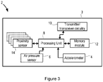
- a fall detection system 2 according to an embodiment of the invention is shown in Fig. 3 .
- the fall detection system 2 is comprised in a user device 3 that is designed to be worn by a user on their wrist, although it will be appreciated that the invention is not limited to this use, and the user device 3 could instead be designed to be worn at the user's waist, on their chest or back, or as a pendant around their neck.
- the user device 3 may be provided in the form of a wrist band, a wrist strap or a watch.
- the fall detection system 2 (user device 3) comprises one or more sensors for measuring the movements of the user 1.
- the fall detection system 2 comprises two movement sensors, an accelerometer 4 that measures the (three-dimensional) accelerations experienced by the fall detection system 2 and an air pressure sensor 6 that measures air pressure or changes in air pressure.
- the movement sensors 4, 6 are connected to a processing unit 8.
- the processing unit 8 receives measurements from the movement sensors 4, 6 and processes the measurements to determine if the user 1 of the fall detection system 2 may have suffered a fall.
- two movement sensors are shown in this embodiment, it will be appreciated that fall detection systems 1 according to alternative embodiments may comprise only one movement sensor (for example just the accelerometer 4).
- the fall detection system 2 can comprise additional or alternative types of movement sensors, such as a gyroscope or magnetometer.
- the fall detection system 2 may also comprise sensors for measuring physiological aspects, such as a skin conductance sensor and/or a photoplethysmograph (PPG) sensor.
- PPG photoplethysmograph
- the fall detection system 2 also comprises transmitter or transceiver circuitry 10 that allows the fall detection system 2 to transmit an alarm signal in the event that a fall is detected, or help is otherwise requested by the user 1 (for example by pressing a personal help button (PHB) present in the system 2).
- the transmitter or transceiver circuitry 10 can be configured to communicate with a base station associated with the fall detection system 2 (which can then issue an alarm or summon help from a healthcare provider or the emergency services) or via a public telephone network (such as a mobile telecommunications network) to a remote station (for example located in call centre of a healthcare provider).
- the circuitry 10 may be configured according to any known wireless technology, for example Wi-Fi, Bluetooth, Near Field Communication (NFC), etc. Where the transmitter or transceiver circuitry 10 is also or alternatively provided to enable communications with a public telephone network, such as a mobile telephone network, the circuitry 10 may be also or alternatively configured for use with any suitable type of second-, third- or fourth-generation communication network, including GSM, WCDMA, LTE, etc. Also, although not shown in Figure 3 , the fall detection system 2 may comprise a loudspeaker and/or microphone for enabling a user 1 to communicate with the healthcare provider or the emergency services.
- the fall detection system 2 may comprise a loudspeaker and/or microphone for enabling a user 1 to communicate with the healthcare provider or the emergency services.
- the fall detection system 2 also comprises a memory module 12 that is connected to the processing unit 8 and that can store measurement data from the movement sensors 4, 6, the results of processing or pre-processing of the measurement data and/or computer readable code to enable the processing unit 8 to execute the fall detection algorithm and/or otherwise control the operation of the fall detection system 2.
- the memory module 12 may only store the latest measurement data and that measurement data may also be transmitted using transmitter or transceiver circuitry 10 to a remote server or via a base station for storage.
- the fall detection system 2 comprises one or more proximity sensors 14 that measure the distance of the fall detection system to the ground, floor or other object.
- the proximity sensor(s) 14 are connected to the processing unit 8.
- the proximity sensor 14 may be mounted in a main housing of the fall detection system 2, or it may be mounted in part of a strap or band that is used to attach the fall detection system 2 to the user 1.
- the proximity sensor 14 preferably measures distances to objects (e.g. the ground or floor) by emitting pulses of sound or light and measuring the time of flight from the emission of the pulse to the receipt of an echo reflected from the object.
- the proximity sensor 14 may comprise a sound or light transducer that performs both the transmission and reception functions, while in other embodiments the proximity sensor 14 may comprise separate transmitter/emitter and receiver components.
- the proximity sensor 14 can measure distances using ultrasound.
- ultrasound When employing ultrasound, a short pulse with a frequency beyond that of human hearing (i.e. greater than 20 kHz) is emitted by the ultrasound transmitter. The receiver then listens for the reflected pulse or echo. Given the speed of sound in the specific medium and the delay between the transmitted pulse and the received echo, the round-trip distance can be determined. The distance between the proximity sensor 14 and the point of reflection corresponds to half the round-trip distance.
- the use of ultrasound to measure the distance is advantageous since ultrasound signals have good directionality (so reflections are likely to only occur from objects generally in 'front' of the transmitter) and there is almost no interference from high-intensity environmental sounds since they will be at a lower frequency than the ultrasound signals.
- the fall detection system 2 includes a temperature sensor and the measured temperature is used to correct the speed of sound value used in the distance (proximity) calculation.
- the fall detection system 2 can include a table stored in the memory module 12 that maps the time-of year (e.g. in terms of season, month, etc) and/or time-of-day to a typical temperature (or a speed of sound based on that typical temperature), that is used to calculate the distance (proximity).
- the proximity sensor 14 can include a light-based transducer, for example an infrared LED or laser combined with a photodiode which is sensitive to the wavelength of the light emitted by the LED, to measure the distance from the sensor 14 to an object.
- a light-based transducer for example an infrared LED or laser combined with a photodiode which is sensitive to the wavelength of the light emitted by the LED, to measure the distance from the sensor 14 to an object.
- the proximity sensor 14 can output the measured distance to the processing unit 8 which translates the measured distance to a proximity measure (e.g. proximate an object or floor or not proximate an object or floor) by comparing the distance to a threshold value, or, alternatively the proximity sensor 14 itself can translate the measured distance into the proximity measure and output the proximity measure to the processing unit 8.
- a proximity measure e.g. proximate an object or floor or not proximate an object or floor
- the fall detection system 2 may comprise multiple proximity sensors 14 that can be distributed around the housing of the fall detection system 2 or wrist band or belt around the waist and arranged in different orientations to enable the distance to the ground, floor or other object to be measured regardless of the orientation of the fall detection system 2 (and thus regardless of the orientation of the user's wrist).
- sensors 14 can be placed in pairs (or more) facing generally the same direction and they can be driven together to create beaming effects in the emitted ultrasound signal. This can enable the width of the "viewing" direction of the sensor 14 to be narrowed, and hence provide a more accurate measurement of the distance in the direction of the beam. This can also enable the direction of the beam to be varied by varying the phase of the signal (pulse) by which neighbouring sensors 14 (pairs/triples in the example) are excited, in relation to the wavelength used. As described in more detail below, varying the direction of the beam allows the proximity measurement to be executed in different directions, which in turn provides a measure of the extendedness of the (proximate) object. In this case, where sensors 14 are distributed around the fall detection system 2 to allow distance to be measured regardless of the orientation of the fall detection system 2, the sensors 14 may be mounted in pairs or triples for beam control, with multiple pairs/triples distributed around the fall detection system 2 for global coverage.
- Multiple proximity sensors 14 may also consist of proximity sensors of different types grouped into one or more clusters which are distributed around the housing of the fall detection system 2. Such an embodiment is beneficial to overcome certain limitations of a given proximity sensor. For example, on the one hand, dark-coloured surfaces absorb light, and thus an ultrasound proximity sensor would provide more accurate proximity detection. On the other hand, sound-absorbing materials may lead to poor ultrasound proximity detection, while infrared-based proximity detectors may be unaffected.
- Multiple proximity sensors 14 may also or alternatively be provided that are to be placed at multiple sites on the user's body. This allows the proximity of different parts of the user's body to the ground or floor to be measured, increasing the reliability of the proximity detection (for example in case the proximity sensor 14 on one part of the body gives a false positive measurement indicating that the body part is not close to the ground or floor).
- at least one of those proximity sensors 14 can be integrated into a separate housing or wearable component to the rest of the components of the fall detection system 2 shown in Fig. 1 .
- those other proximity sensors 14 will be provided with means to enable the proximity or distance measurements to be communicated to the processing unit 8 for analysis.
- the measurements may be communicated through a wired or wireless (e.g. WiFi, Bluetooth, Near Field Communication (NFC) or ZigBee) connection to the main fall detection system unit 2.
- Fig. 3 only shows the components of the fall detection system 2 required to illustrate the invention, and the fall detection system 2 can comprise other components to those shown.
- the fall detection system 2 will comprise a battery or other portable power source.
- the fall detection system 2 may further comprise an audible alarm unit that can be activated by the processing unit 8 in the event that the processing unit 8 determines that the user 1 has suffered a fall.
- the fall detection system 2 may also be provided with a button (also not shown in Fig. 3 ) that allows the user 1 to manually activate the audible alarm unit if they require assistance (or, in some cases, to deactivate the alarm if assistance is not required).
- the fall detection system 2 may comprise a satellite positioning system (SPS) receiver, such as a Global Positioning System (GPS) receiver, for tracking the location of the fall detection system 2.
- SPS satellite positioning system
- GPS Global Positioning System
- Information on the location of the fall detection system 2 can be transmitted to the call centre in the event that an alarm is triggered to enable help or assistance to be sent to the right location.
- the fall detection system 2 can comprise a user device 3 that generally corresponds to the user device 3 shown in Fig. 3 , but the fall detection system 2 further comprises a base unit that is to be located in the home of the user 1 and that communicates wirelessly with the user device 3.
- the base unit may also act as a charging station for the user device 3.
- the base unit may comprise circuitry for enabling communications between the user and a remote call centre (such as the emergency services) via a public switched telephone network and/or a mobile communications network, and/or may provide a connection to the Internet.
- the processing and operations according to the invention can be performed by the processing unit 10 in the user device 3, with the base unit being provided merely to facilitate communications with the remote call centre/emergency services/Internet.
- the user device 3 can communicate the measurements obtained by the movement sensors 4, 6 and proximity sensor(s) 14 to the base unit using the transmitter/transceiver circuitry 10, and a processing unit in the base unit can perform the processing and operations according to the invention using the measurements.
- This latter embodiment has the advantage that the power consumption of the user device 3 can be substantially reduced.
- the connection can be made using any known wireless technology, for example Wi-Fi, Bluetooth, Zigbee, Near Field Communication (NFC), etc.
- the fall detection system 2 uses a fall detection algorithm that processes the proximity value measured by the proximity sensor 14 together with other features (e.g., height change, impact, orientation, etc.) derived from the measurements from the movement sensor(s) 4, 6 to determine if the user 1 has fallen.
- it is determined whether the set of feature values (including the proximity sensor value) is in a (multidimensional) region corresponding to a fall.
- a value indicating the likelihood of a fall is determined for the set of feature values, and this likelihood is compared to a threshold to determine if a fall has occurred.
- each individual feature value can be compared to a respective threshold, and a fall detected if a certain number of features exceed their threshold value.
- the full fall detection algorithm can be executed in stages, with a feature or various features being derived at each stage, and each stage is only triggered if the features derived in the previous stage are consistent with a fall having taken place. The derived features are then tested in a classifier to determine if a fall has taken place. This type of staged computation of feature values, with each value being tested against a threshold, is referred to as a state machine.
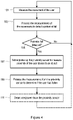
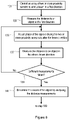
- a method of operating the fall detection system 2 to detect whether the user 1 has fallen is shown in Fig. 4 .
- a proximity sensor 14 can consume a lot of power if it is active all of the time, and as the proximity sensor 14 may only provide a useful measurement of its feature (i.e. the proximity of the fall detection system 2/user 1 to the ground or floor after an impact or height change event) once a fall has occurred, the proximity sensor 14 is only activated if a potential fall is detected following some processing of the measurements from one or more of the movement sensors 4, 6.
- This embodiment enables a proximity sensor 14 to be used to improve the reliability of the fall detection algorithm without substantially increasing the average power consumption of the fall detection system 2.
- step 101 the movements of the user 1 are measured using the one or more movement sensors 4, 6. That is, one or more of the movement sensors 4, 6 are active (i.e. powered) and measurements of the movements are provided by the sensors 4, 6 to the processing unit 8 for analysis.
- the proximity sensor(s) 14 are inactive and thus not emitting sound or light (as appropriate for the type of sensor).
- the processing unit 8 can control the fall detection system 2 so that power is not supplied to the proximity sensor(s) 14, but in other cases power can continue to be supplied to the proximity sensor components, but the processing unit 8 controls the proximity sensor(s) 14 so that they do not activate their transducers.
- the processing unit 8 processes the measurements of the movements of the user 1 obtained in step 101 to determine whether the user 1 may have suffered a fall.
- the measurements are only processed to determine whether a fall may have potentially occurred (i.e. the measurements are processed to see if there is some indicator or trigger feature that a fall has taken place), and therefore whether further measurements and/or more detailed analysis of the measurements (i.e. execution of the full fall detection algorithm) may be required to confirm whether a fall has actually occurred and an alarm needs to be triggered.
- a fall can be broadly characterised by, for example, a change in altitude of around 0.5 to 1.5 metres (the range may be different depending on the part of the body that the fall detection system 2 is to be worn and the height of the user 1), culminating in a significant impact, followed by a period in which the user 1 does not move very much.
- movement sensor measurements can be processed to extract values for one or more features including a change (specifically a reduction) in height/altitude (which is usually derived from the measurements from the air pressure sensor 6, but can also or alternatively be derived from the measurements from the accelerometer 4, for example if the air pressure sensor 6 is omitted), a maximum activity level (i.e.
- an impact around the time that the change in altitude occurs (typically derived from the measurements from the accelerometer 4), a period in which the user 1 is relatively inactive following the impact (again typically derived from the measurements from the accelerometer 4), the vertical velocity, the occurrence of free fall (typically derived from measurements from the accelerometer 4), a change in orientation upon falling (typically derived from the measurements from the accelerometer 4 or from a gyroscope, if present) and an indication of a height/altitude increase after a detected impact.
- step 103 the processing unit 8 preferably processes the movement measurements to detect a selected trigger feature that typically occurs during a fall, with the detection of this selected (trigger) feature providing an indication that a fall has potentially occurred (the other features of a fall, for example those listed above, are not computed by the processing unit 8 at this stage).
- this limited processing of the movement sensor measurements for a single trigger feature helps to minimise the power consumption of the fall detection system 2.
- step 103 the processing unit 8 processes the movement measurements to detect if a certain height change (and in particular a height drop) has occurred.
- the required height change can be 0.5 metres, or any other suitable value taking into account where on the user's body the fall detection system 2 is carried and/or on the height or other physical characteristics of the user 1.
- the processing unit 8 can process the movement measurements to detect if an impact (which a magnitude greater than a threshold value) is present in the movement measurements to identify if a fall has potentially occurred.
- the processing unit 8 can process the movement measurements to detect if a different feature or further features, e.g. a free-fall longer than a threshold time period , are present in the movement measurements to identify if a fall has potentially occurred.
- step 103 can be performed in real-time or near real-time to detect a potential fall as soon as it has occurred, or even to detect a potential fall during the physical act of falling itself.
- a potential fall (as indicated by a height drop greater than a threshold height drop or free fall for longer than a threshold time period) can be detected before the user 1 impacts the ground.
- step 105 it is determined whether a potential fall has been detected. For example, where step 103 comprises determining the height change, a potential fall is detected if a drop in height of at least 0.5 metres is detected in the movement measurements. Where step 103 comprises determining an impact magnitude, a potential fall is detected if an impact is detected that has a magnitude greater than a threshold value.
- step 103 If no potential falls are detected in step 103 (e.g. there is no or an insufficient height drop or an impact of insufficient magnitude), the method returns to step 101 and further measurements of the movements of the user 1 are collected and analysed for a potential fall.
- Step 107 in which the proximity sensor(s) 14 is activated in order to measure the proximity of the part of the body of the user 1 to which the fall detection system 2/user device 3 is attached to the ground or floor.
- Step 107 may comprise the processing unit 8 controlling the fall detection system 2 so that power is supplied to the proximity sensor(s) 14, thereby activating the transducers to emit light or sound as appropriate, or may comprise the processing unit 8 directly controlling the proximity sensor(s) 14 to activate their transducers.
- the distance(s) measured by the proximity sensor(s) 14 or the proximity measure(s) are output to the processing unit 8.
- a potential fall may be detected while the actual fall is still in progress, which can result in the proximity sensor(s) 14 being activated/powered on before an impact occurs.
- the fall detection algorithm is based on a state machine concept
- the detection of a potential fall in step 105 it is possible for the detection of a potential fall in step 105 to be based on the staged detection of multiple fall features before it is decided to activate the proximity sensor 14 in step 107.
- an alarm can be issued by the fall detection system 2 in order to start the process of getting help to the user 1.
- step 109 the processing unit 8 (or processing unit in a base station in the alternative embodiment) processes the measurements from the proximity sensor(s) 14 to determine if the user 1 has fallen.
- step 109 can comprise simply determining whether the fall detection system 2 is proximate the ground or floor and accepting or rejecting the potential fall on that basis (i.e. if the system 2 is proximate the ground or floor (e.g. the distance ⁇ d) the potential fall is confirmed, and if the system 2 is not proximate the ground or floor (e.g. the distance > d) the potential fall is rejected).
- step 109 can comprise inputting the measured proximity and the previously computed trigger features into a classifier to determine whether a fall has occurred.
- step 109 can comprise the continuation of a state machine process in which one or more further features are computed from the movement sensor measurements, and then a fall detected after the features are input to a classifier.
- step 109 can comprise determining one or more further fall features from the movement sensor measurements and processing those fall features along with the proximity measurement to determine if the user 1 has fallen.
- a change in proximity of the fall detection system 2 to the ground or floor can be calculated (if the proximity sensor 14 is activated early enough during the ongoing fall) and compared to the computed height change, and the result of this comparison can be input to the fall detection algorithm.
- step 109 The analysis performed by the processing unit 8 in the embodiments of step 109 will not be described in detail herein since those skilled in the art will be aware of various algorithms and techniques that can be used to determine whether a user has suffered a fall from movement sensor measurements.
- a set of feature values derived from the measurements is provided to a classifier that has been optimised to decide between falls and non-falls based on the feature values.
- the proximity measurements can be input into this classifier as an additional feature value and used to affect or derive a likelihood value that a fall has occurred. As discussed below with reference to Figs.
- a feature that can be input to the threshold sequence (state machine) or classifier that is derived using the proximity sensor 14 is the extent or 'extendedness' of the object to which the distance has been measured. This extent or extendedness indicates how likely the object to which the distance has been measured is a floor or the ground.
- the proximity sensor(s) 14 are deactivated/powered down to minimise the power consumption of the fall detection system 2 (step 111).
- the proximity sensor(s) 14 can be used to detect whether the user 1 gets up after a detected fall. Thus, if a fall is detected in step 109, the proximity sensor(s) 14 can remain powered or activated to continue measuring the distance between the sensor(s) 14 and an object/floor.
- the processing unit 8 can monitor the measured distances output by the proximity sensor(s) 14 to determine if the user 1 gets up (for example by detecting if the measured distance becomes greater than the threshold distance d). Once it has been detected that the user 1 has got up, the proximity sensor(s) 14 may be powered down/deactivated as shown in step 111. In some cases, the detection of whether the user 1 has got up using the proximity measurements can also take into account the orientation of the fall detection unit 2 (as discussed below) in order to distinguish a user 1 getting up from the floor from the user 1 reaching upwards to try and get up.
- the fall detection system 2 can trigger an alarm to summon help to the user 1. Triggering an alarm may comprise activating an audible alarm unit in the fall detection system 2, and/or initiating a call or otherwise sending an alarm message or signal to a remote location (such as a call centre or the emergency services).
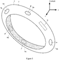
- the fall detection system 2 can comprise multiple proximity sensors 14 that can be distributed around the housing of the fall detection system 2 or wrist band and arranged in different orientations to enable the distance to the ground, floor or other object to be measured regardless of the orientation of the fall detection system 2 (and thus regardless of the orientation of the user's wrist).
- a fall detection system 2 according to this embodiment is shown in Fig. 5 .
- the fall detection system 2/user device 3 is in the form of a wrist band with five proximity sensors 14a-14e distributed around the wrist band (although more or less proximity sensors can be provided).
- the proximity sensors 14a-14e each face outwards from the wrist band (as indicated by the dashed arrows).
- the wrist band also includes a housing 16 that contains the other components of the fall detection system 2 (e.g. as shown in Fig. 3 ).
- step 107 of Fig. 4 can comprise activating or powering up all of the proximity sensors 14a-14e if a potential fall is detected.
- the proximity sensors 14a-14e can be activated in a round-robin (i.e., consecutive) approach to prevent cross-talk between the proximity sensors, and a proximity map as a function of the azimuth angle can be calculated with respect to the location of one of the proximity sensors 14a-14e as a reference. This 'reference' sensor can be the proximity sensor 14 that is facing downward.
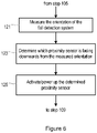
- Fig. 6 shows various exemplary steps for implementing this feature in the fall detection system 2 in place of step 107 in Fig. 4 .
- step 121 which takes place after a potential fall is detected in step 105, the measurements from the accelerometer 4 in the fall detection device 2 are processed to identify the component of acceleration due to gravity and the direction in which gravity is acting.
- the direction in which gravity is acting indicates the orientation of the fall detection device 2, and more precisely it indicates the vertical direction and hence the direction at which the (proximate) floor, if present, should be expected.
- step 123 it is determined which of the proximity sensors 14a-14e is facing downwards from the determined orientation of the fall detection system 2.
- the fall detection device 2 can be preconfigured with the identity of the proximity sensor 14a-e to use for a given orientation of the fall detection system 2 (although those skilled in the art will appreciate that this can be implemented in alternative ways).
- this step can comprise looking up the appropriate proximity sensor 14a-e to use for the determined orientation.
- the appropriate proximity sensor to measure the distance to the ground or floor is sensor 14c.
- step 125 the selected proximity sensor 14a-e is activated or powered up to measure the distance to the ground or floor. The method then moves to step 109 of Fig. 4 and proceeds as described above.
- step 125 can comprise activating an array of proximity sensors 14 determined in step 123 to be facing downwards (or the nearest to facing downwards) and driving the array of proximity sensors to direct the beam downwards to measure the distance/proximity to the ground or floor.
- the method of activating an appropriate proximity sensor 14 according to the orientation of the fall detection system 2 can be applied to fall detection systems 2 that do not apply the power reduction method in Fig. 4 and that continuously operate at least one proximity sensor 14 to measure the distance to the ground or floor.
- the orientation of the fall detection device 2 is continuously monitored and the proximity sensor 14 that is facing downwards is activated or powered on. If or when the orientation changes so that the active proximity sensor 14 is no longer the most downward facing sensor 14, the fall detection system 2 switches to using the most downwards facing proximity sensor 14.
- each proximity sensor 14 can be detected by including a respective orientation sensor (such as an accelerometer or magnetometer) with each proximity sensor 14 and determining the direction in which gravity acts at each proximity sensor 14 from the measurements of the acceleration or magnetic field at each site.
- a respective orientation sensor such as an accelerometer or magnetometer
- the determined direction of gravity can then be used to determine the direction in which each proximity sensor 14 is facing, and this information can be used in the method of Fig. 6 to select an appropriate proximity sensor 14 to activate or power up.
- the analysis of the orientation of each proximity sensor 14 may only need to be performed when the system 2 is first switched on by the user 1, although in other cases the analysis can be repeated after some time interval.
- multiple proximity sensors 14 can be placed in a linear or non-linear 1-, 2- or 3-dimensional array of two, three or more sensors that face generally the same direction and that are driven together to utilise beam forming effects to enable the width of the viewing direction to be changed and/or to enable the direction of the beam to be varied or steered. Varying the direction of the beam allows the proximity measurement to be executed in different directions, which in turn allows a measure of the extent or extendedness of the (proximate) object to be determined.
- the extension of the object to which the distance has been measured by the proximity sensor 14 can indicate whether the object is the ground or floor, or some other object, such as a table or door.
- a large extension i.e. the object extends for some distance raises the likelihood that the object is the ground or floor.
- Fig. 7 illustrates a scenario not forming part of the invention in which determining the extent of a detected object may be useful.
- a user 1 that is wearing a fall detection system 2 on their wrist is sat at a table 18.
- a proximity sensor 14 in the system 2 will measure the distance to an object below the system 2. As the user's wrist is above the table 18, the distance measured will be quite short, and, in this case, below the threshold distance d that is used to determine if the user 1/system 2 is proximate the ground or floor.
- the proximity sensor 14 may provide a measurement that incorrectly indicates that the user 1/system 2 is on the floor.
- an array of proximity sensors 14 can be controlled to measure the extent of the detected object, which in the example of Fig. 7 will reveal a significantly larger distance to an object when the beam is directed past the edge 20 of the table 18 (particularly in the direction of the elbow of the user 1, which may be known if the orientation of the fall detection system 2 on the user's wrist is known), thereby reducing the likelihood that the measured distance (that is below d) is a distance to the ground or floor.
- Fig. 8 illustrates a method not forming part of the invention of determining the extent or extendedness of an object that can be performed as part of step 107 of Fig. 4 .
- the processing unit 8 controls the array to emit a beam of light or sound (as appropriate) in a first direction (step 131).
- the control of the array in step 131 comprises applying driving signals to each of the proximity sensors 14 with a known phase difference between the driving signals. The phase difference between the emissions from each sensor 14 will cause the emissions to interfere and produce a directed beam.
- the distance to an object is measured using the beam emitted in the first direction (step 133).
- This step is performed in a similar way to a single proximity sensor 14 embodiment and involves determining the round trip time of the emitted signal and the reflection from the object.
- step 135 the relative phase of the driving signals is changed to alter the beam direction.
- the distance to an object is measured in the altered beam direction (step 137).
- step 139 it is determined whether enough distance measurements have been taken. If not, the method returns to step 135 and repeats for a new direction. Since the aim of this method is to detect whether the user is lying down on the ground or floor, the search for an (abrupt) edge is best performed in the direction of the user's body, i.e. in the direction of the arm, which may be known if the orientation of the fall detection system 2 on the user's wrist is known. Furthermore, the abrupt edge should be within a body's length of the fall detection system 2.
- step 141 the extent or extendedness of the object is determined by analysing the distance measurements for the different directions.
- objects of a certain extent such as a table 18, but with a clear, abrupt edge (e.g. edge 20)
- edge 20 will be detectable in the measurements since there will be a significant increase in the measured distance after a series of generally consistent distance measurements.
- the distance will equal (h 0 )/cos( ⁇ ), where ⁇ is the angle between the direction of measuring and the vertical (which will be known from the direction of gravity in the measurements from the accelerometer 4), and ho is the distance in the vertical direction.
- the ground or floor is not of infinite length and there may be walls nearby, but, in general, at the walls the measured distance will not sharply increase. This can be discerned from the measured distances.
- the ground or a floor can be characterised by a high proximity (i.e. low distance), a large extension, and no abrupt distance increments at its edges (on all sides).
- the determined distance and extent is then processed in step 109 of Fig. 4 with the other feature values derived from the movement sensor measurements.
- the change in the received echo strength as a function of the relative phase of the beam angle can also be used as a measure of extendedness.
- Fig. 8 which is not forming part of the invention, multiple proximity sensors 14 are driven together to create beams and in that way refine the accuracy of the measurement.
- another option is to combine the information from multiple sensors 14 distributed around the fall detection system 2, as in Fig. 5 .
- another feature value that can be provided by the proximity sensors 14 and that can affect the fall detection process is the relative strength of the echo or reflection of the energy emitted by the proximity sensor 14.
- the relative strength of the echo or reflection can indicate how hard or soft the surface that reflected the beam is (with a high strength indicating a hard surface and a low strength indicating a soft surface), and can also indicate the reliability of the distance estimate obtained from that surface (with a reliable range estimate requiring a strong echo).
- the proximity sensors 14 sequentially emit and listen for the echo pulse. Given the position of the proximity sensors 14 with respect to each other a proximity image of the nearby object and environment can be derived from the resulting proximity measurements.
- one or more arrays of proximity sensors 14 can be used to measure the distance to different parts of the body of the user 1 (e.g. by directing the beam in different directions), and then the posture of the user 1 can be inferred from the proximity measurements and a known orientation of the fall detection system 2 (and thus wrist).
- proximity measurements of different parts of the body from head to feet may enable the fall detection system 2 to distinguish between a sitting posture (e.g. as shown in Fig. 7 ), a standing posture (e.g. as shown in Fig. 1 ) and a lying posture (e.g. as shown in Fig. 2 ).
- a computer program may be stored/distributed on a suitable medium, such as an optical storage medium or a solid-state medium supplied together with or as part of other hardware, but may also be distributed in other forms, such as via the Internet or other wired or wireless telecommunication systems. Any reference signs in the claims should not be construed as limiting the scope.
Description
- The invention relates to a method for detecting falls by a user and a fall detection system implementing the same, and in particular relates to a method for detecting falls and a fall detection system that provides increased fall detection reliability.
- Falls affect millions of people each year and result in significant injuries, particularly among the elderly. In fact, it has been estimated that falls are one of the top three causes of death in elderly people. A fall is defined as a sudden, uncontrolled and unintentional downward displacement of the body to the ground, followed by an impact, after which the body stays down on the ground.
- PERS is a system in which help can be assured. By means of Personal Help Buttons (PHBs) the user can push the button to summon help in an emergency. A majority of calls are because the user has fallen. Also, if the user suffers a severe fall (for example by which they get confused or even worse if they are knocked unconscious), the user might be unable to push the button, which might mean that help doesn't arrive for a significant period of time, particularly if the user lives alone. The consequences of a fall can become more severe if the user stays lying for a long time.
- Fall detection systems are also available that process the output of one or more movement sensors to determine if the user has suffered a fall. Most existing body-worn fall detection systems make use of an accelerometer (usually an accelerometer that measures acceleration in three dimensions) and they are configured to infer the occurrence of a fall by processing the time series generated by the accelerometer. Some fall detection systems can also include an air pressure sensor, for example as described in
WO 2004/114245 , for measuring the height, height change or absolute altitude of the fall detection system. On detecting a fall, an alarm is triggered by the fall detection system. - In general, a fall detector tests on features like impact, orientation, orientation change, height change, vertical velocity, and alike. Reliable detection results when the set of computed values for these features is different for falls than for other movements that are not a fall.
- Some fall detection systems are designed to be worn as a pendant around the neck of the user, whereas others are designed to be worn on or at the torso (e.g. waist, on a waist belt or in a pocket) or on the limbs of the user, for example at the wrist. However, the wrist is capable of complex movement patterns and has a large range of movement shapes/forms/types, and is also susceptible to non-fall related impacts in which the hand, wrist or arm strikes an object, e.g. furniture or a door frame, during normal movement by the user, which means that existing fall detection methods based on analysing measurements from an accelerometer do not provide a sufficiently high detection rate while minimising the number of false alarms for this type of fall detection system.
- Therefore there is a need for a method for detecting falls and a fall detection system that provides increased fall detection reliability, particularly a fall detection system that is worn on the wrist.
- According to a first aspect of the invention, there is provided a fall detection system according to
claim 1. - In some embodiments, the movement sensor further includes an air pressure sensor.
- In some embodiments, the processing unit is configured to process the measurements to detect if a potential fall has occurred by processing the measurements to determine a change in height and/or the magnitude of an impact, and to detect a potential fall if the change in height is greater than a first threshold value and/or the magnitude of the impact is greater than a second threshold value.
- In preferred embodiments, the processing unit is configured to process the measurements from the proximity sensor and the measurements from the movement sensor to determine if the user has fallen.
- In some embodiments, the user device comprises a plurality of proximity sensors that are distributed in different orientations around the user device.
- In some embodiments, the processing unit is configured to activate each of the plurality of proximity sensors if a potential fall is detected.
- In other embodiments, the processing unit is configured to, on detection of a potential fall, process the measurements from the movement sensor to determine the orientation of the user device, determine which of the plurality of proximity sensors is facing downwards from the determined orientation, and activate the proximity sensor that is determined to be facing downwards.
- In some embodiments, each proximity sensor has an associated orientation sensor for determining the orientation of the proximity sensor, and the processing unit is configured to measure the orientation of each proximity sensor using the orientation sensors, and to determine the direction in which each proximity sensor is facing from the measured orientations. In preferred embodiments, the user device comprises the processing unit. In alternative embodiments, the fall detection system further comprises a base unit that is configured to communicate wirelessly with the user device, the base unit comprising the processing unit.
- According to a second aspect, there is provided a method according to
claim 8. - In some embodiments, the step of processing the measurements to detect if a potential fall has occurred comprises processing the measurements to determine a change in height and the magnitude of an impact, and detecting a potential fall if the change in height is greater than a first threshold value and the magnitude of the impact is greater than a second threshold value.
- In preferred embodiments, the step of processing the measurements to determine if the user has fallen comprises processing the measurements from the proximity sensor and the measurements from the movement sensor to determine if the user has fallen.
- In some embodiments, there are a plurality of proximity sensors distributed in different orientations around a user device. In those embodiments, the step of activating a proximity sensor comprises activating each of the plurality of proximity sensors if a potential fall is detected. In alternative embodiments, on detecting a potential fall, the method further comprises the step of processing the measurements from the movement sensor to determine the orientation of the user device, and determining which of the plurality of proximity sensors is facing downwards from the determined orientation, and the step of activating comprises activating the proximity sensor that is determined to be facing downwards.
- In some embodiments, each proximity sensor has an associated orientation sensor, and the step of determining which of the plurality of proximity sensors is facing downwards comprises using the measurements from each associated orientation sensor to determine which proximity sensor is facing downwards.
- According to the third aspect, there is provided a computer program product having computer readable code embodied therein, the computer readable code being configured such that, on execution by a suitable computer or processing unit, the computer or processing unit performs any of the methods described above.
- Exemplary embodiments of the invention will now be described, by way of example only, with reference to the following drawings, in which:
-
Fig. 1 shows a user wearing a wrist-worn fall detection system according to the invention, with the user upright or walking; -
Fig. 2 shows a user wearing a wrist-worn fall detection system according to the invention, with the user lying on the ground or floor; -
Fig. 3 is a block diagram of a fall detection system in accordance with an embodiment of the invention; -
Fig. 4 is a flow chart illustrating a method of operating a fall detection system according to a first embodiment; -
Fig. 5 is an illustration of a fall detection system according to a second embodiment; -
Fig. 6 is a flow chart illustrating a method of operating a fall detection system according to the second embodiment; -
Fig. 7 shows a user wearing a wrist-worn fall detection that is upright and close to a table; and -
Fig. 8 is a flow chart illustrating a method of operating a fall detection system according to an example not forming part of the invention. - As described above in the Background section, it has been found that existing fall detection methods based on the analysis of measurements from movement sensors in a wrist-worn fall detection system do not provide a sufficiently high detection rate while limiting the number of false alarms due to the movements and apparent impacts of the wrist that can occur in normal daily activities, such as walking, sitting, etc., that do not otherwise result from falls by the user. These existing fall detection methods derive features including orientation change, height change, vertical velocity and/or impact magnitude from the movement sensor measurements to determine if the user of the fall detection system has suffered a fall.
- Thus, in accordance with the invention, the reliability of a wrist-worn fall detection system is improved by including an additional sensor in the fall detection system that can measure the proximity of the fall detection system to the ground or floor. The proximity sensor may use one or more modalities for detecting the proximity of the fall detection system to the ground or floor.
- In preferred embodiments, the proximity sensor uses sound or light to measure the distance to an object by measuring the time between the emission of a pulse of sound or light and the receipt of an echo (reflection) of the pulse. The round-trip distance (and thus the distance to the object that produced the echo) can be determined using the known speed of sound or light in a particular medium and the measured time. Furthermore, the intensity of the reflected sound or light signal may be used as a measure of the distance and/or surface type. In some cases, since the distance between the proximity sensor and the object may be changing as the distance is measured, there may be a Doppler shift in the received reflection of the pulse, and this Doppler shift can be analysed as part of the proximity detection.
- The proximity sensor can also or alternatively measure changes in capacitance or inductance to estimate the proximity to an object. Changes in the electric or magnetic field for a capacitive or inductive proximity sensor, respectively, can indicate whether an object is in proximity to the sensor.
- As an example not forming part of the invention, the proximity sensor can comprise a light sensor that measures light brightness, and the brightness level can be used to estimate the proximity to an object. For example, when the measured brightness level is low (possibly following a period where the measured brightness was relatively high), this can indicate that the light sensor has been occluded by an object, such as the floor. A light sensor can also or alternatively determine proximity by measuring focus depth to an object and/or breadth of view.
- The proximity of the fall detection system to the floor or ground measured using this sensor will provide another feature that can be used in the fall detection algorithm to determine if the user has fallen.
- Typically, a proximity sensor according to the invention consists of an emitter which emits a short pulse of sound or light and a receiver which measures the corresponding signal that is reflected off of the surface of an object that is in proximity to the sensor. Proximity sensors are often designed so that the emitter and receiver are placed in close proximity, while preventing a direct coupling between the two. The sensitivity response of the receiver is also designed to closely match the response of the emitter's signal. For example an ultrasound-based proximity sensor that emits an ultrasonic signal at 40 kHz will preferably include a receiver with its peak response centred at 40 kHz. The light transducers found in some computer mice may be suitable for use as a proximity sensor in a fall detection system according to embodiments described herein. In those embodiments, it may also be useful to use that light sensor to measure the displacement of the sensor over the object or surface (e.g. floor).
-
Figs. 1 and 2 illustrate the use of a fall detection system that includes a proximity sensor in determining whether a user has fallen. Theuser 1 is carrying or wearing afall detection system 2 that includes a proximity sensor on their wrist. The proximity sensor in thefall detection system 2 preferably (but not necessarily) emits pulses of sound or light as described above to measure the distance to the ground or floor. Thefall detection system 2 can apply a threshold to the measurements from the proximity sensor to determine if the fall detection system 2 (and thus the wrist of the user 1) is close enough to the ground or floor to suggest a possible fall. This threshold distance is denoted d inFigs. 1 and 2 and has a typical value in the region of 0.1 metres to 0.5 metres. - When the
user 1 is standing or walking normally as inFig. 1 , the distance measured by the proximity sensor in thefall detection system 2 will be greater than the threshold distance, suggesting that theuser 1 is not lying on the ground or floor. This feature reduces the likelihood of the fall detection algorithm detecting that a fall has taken place. Using conventional fall detection algorithms, if theuser 1 accidently bumps their wrist against some furniture, producing a measurable impact, and there is some orientation and height change (which can occur in the normal movements of the user's wrist), a fall might be detected. However, the measurement of the proximity sensor used according to the invention will indicate that the wrist is not close to the floor or ground, which will reduce the likelihood of this event being classified as a fall. Also, it may be that the configuration of the fall detection algorithm (e.g. certain assumptions, thresholds and/or parameters used in the algorithm) may produce an output indicating a fall (or not), which the use of a proximity sensor according to the invention can help to isolate as false alarms. For example, if the user lifts their wrist and drops it again, the algorithm might happen to examine the height change in the time interval between the lift and drop and conclude that a significant height drop has occurred, but if the algorithm examined the height drop from the height just before the lift, no height drop would be detected. - However, if the
user 1 has fallen and they are lying on the ground or floor as shown inFig. 2 , the distance measured by the proximity sensor in thefall detection system 2 will be less than the threshold distance d, and the detection of this feature can increase the likelihood of a fall being detected by the fall detection algorithm. - A
fall detection system 2 according to an embodiment of the invention is shown inFig. 3 . In a preferred embodiment of the invention, thefall detection system 2 is comprised in auser device 3 that is designed to be worn by a user on their wrist, although it will be appreciated that the invention is not limited to this use, and theuser device 3 could instead be designed to be worn at the user's waist, on their chest or back, or as a pendant around their neck. In the wrist-worn embodiment, theuser device 3 may be provided in the form of a wrist band, a wrist strap or a watch. - The fall detection system 2 (user device 3) comprises one or more sensors for measuring the movements of the
user 1. In this embodiment, thefall detection system 2 comprises two movement sensors, anaccelerometer 4 that measures the (three-dimensional) accelerations experienced by thefall detection system 2 and anair pressure sensor 6 that measures air pressure or changes in air pressure. Themovement sensors processing unit 8. Theprocessing unit 8 receives measurements from themovement sensors user 1 of thefall detection system 2 may have suffered a fall. Although two movement sensors are shown in this embodiment, it will be appreciated that falldetection systems 1 according to alternative embodiments may comprise only one movement sensor (for example just the accelerometer 4). In yet further examples not forming part of the invention, thefall detection system 2 can comprise additional or alternative types of movement sensors, such as a gyroscope or magnetometer. In some embodiments, thefall detection system 2 may also comprise sensors for measuring physiological aspects, such as a skin conductance sensor and/or a photoplethysmograph (PPG) sensor. - The
fall detection system 2 also comprises transmitter ortransceiver circuitry 10 that allows thefall detection system 2 to transmit an alarm signal in the event that a fall is detected, or help is otherwise requested by the user 1 (for example by pressing a personal help button (PHB) present in the system 2). The transmitter ortransceiver circuitry 10 can be configured to communicate with a base station associated with the fall detection system 2 (which can then issue an alarm or summon help from a healthcare provider or the emergency services) or via a public telephone network (such as a mobile telecommunications network) to a remote station (for example located in call centre of a healthcare provider). Where the transmitter ortransceiver circuitry 10 is configured to communicate with a base station, thecircuitry 10 may be configured according to any known wireless technology, for example Wi-Fi, Bluetooth, Near Field Communication (NFC), etc. Where the transmitter ortransceiver circuitry 10 is also or alternatively provided to enable communications with a public telephone network, such as a mobile telephone network, thecircuitry 10 may be also or alternatively configured for use with any suitable type of second-, third- or fourth-generation communication network, including GSM, WCDMA, LTE, etc. Also, although not shown inFigure 3 , thefall detection system 2 may comprise a loudspeaker and/or microphone for enabling auser 1 to communicate with the healthcare provider or the emergency services. - The
fall detection system 2 also comprises amemory module 12 that is connected to theprocessing unit 8 and that can store measurement data from themovement sensors processing unit 8 to execute the fall detection algorithm and/or otherwise control the operation of thefall detection system 2. - It will be appreciated that the
memory module 12 may only store the latest measurement data and that measurement data may also be transmitted using transmitter ortransceiver circuitry 10 to a remote server or via a base station for storage. - In accordance with the invention, the
fall detection system 2 comprises one ormore proximity sensors 14 that measure the distance of the fall detection system to the ground, floor or other object. The proximity sensor(s) 14 are connected to theprocessing unit 8. Theproximity sensor 14 may be mounted in a main housing of thefall detection system 2, or it may be mounted in part of a strap or band that is used to attach thefall detection system 2 to theuser 1. - As noted above, the
proximity sensor 14 preferably measures distances to objects (e.g. the ground or floor) by emitting pulses of sound or light and measuring the time of flight from the emission of the pulse to the receipt of an echo reflected from the object. Theproximity sensor 14 may comprise a sound or light transducer that performs both the transmission and reception functions, while in other embodiments theproximity sensor 14 may comprise separate transmitter/emitter and receiver components. - In particular embodiments, the
proximity sensor 14 can measure distances using ultrasound. When employing ultrasound, a short pulse with a frequency beyond that of human hearing (i.e. greater than 20 kHz) is emitted by the ultrasound transmitter. The receiver then listens for the reflected pulse or echo. Given the speed of sound in the specific medium and the delay between the transmitted pulse and the received echo, the round-trip distance can be determined. The distance between theproximity sensor 14 and the point of reflection corresponds to half the round-trip distance. The use of ultrasound to measure the distance is advantageous since ultrasound signals have good directionality (so reflections are likely to only occur from objects generally in 'front' of the transmitter) and there is almost no interference from high-intensity environmental sounds since they will be at a lower frequency than the ultrasound signals. - As the speed of sound in a specific medium depends on the temperature of that medium, in some embodiments the
fall detection system 2 includes a temperature sensor and the measured temperature is used to correct the speed of sound value used in the distance (proximity) calculation. Instead of providing a temperature sensor, if correction of the speed of sound is required for temperature, thefall detection system 2 can include a table stored in thememory module 12 that maps the time-of year (e.g. in terms of season, month, etc) and/or time-of-day to a typical temperature (or a speed of sound based on that typical temperature), that is used to calculate the distance (proximity). - In alternative embodiments, the
proximity sensor 14 can include a light-based transducer, for example an infrared LED or laser combined with a photodiode which is sensitive to the wavelength of the light emitted by the LED, to measure the distance from thesensor 14 to an object. - The
proximity sensor 14 can output the measured distance to theprocessing unit 8 which translates the measured distance to a proximity measure (e.g. proximate an object or floor or not proximate an object or floor) by comparing the distance to a threshold value, or, alternatively theproximity sensor 14 itself can translate the measured distance into the proximity measure and output the proximity measure to theprocessing unit 8. - In some embodiments, as described in more detail below with reference to
Fig. 5 , thefall detection system 2 may comprisemultiple proximity sensors 14 that can be distributed around the housing of thefall detection system 2 or wrist band or belt around the waist and arranged in different orientations to enable the distance to the ground, floor or other object to be measured regardless of the orientation of the fall detection system 2 (and thus regardless of the orientation of the user's wrist). - Where
multiple proximity sensors 14 are provided,sensors 14 can be placed in pairs (or more) facing generally the same direction and they can be driven together to create beaming effects in the emitted ultrasound signal. This can enable the width of the "viewing" direction of thesensor 14 to be narrowed, and hence provide a more accurate measurement of the distance in the direction of the beam. This can also enable the direction of the beam to be varied by varying the phase of the signal (pulse) by which neighbouring sensors 14 (pairs/triples in the example) are excited, in relation to the wavelength used. As described in more detail below, varying the direction of the beam allows the proximity measurement to be executed in different directions, which in turn provides a measure of the extendedness of the (proximate) object. In this case, wheresensors 14 are distributed around thefall detection system 2 to allow distance to be measured regardless of the orientation of thefall detection system 2, thesensors 14 may be mounted in pairs or triples for beam control, with multiple pairs/triples distributed around thefall detection system 2 for global coverage. -
Multiple proximity sensors 14 may also consist of proximity sensors of different types grouped into one or more clusters which are distributed around the housing of thefall detection system 2. Such an embodiment is beneficial to overcome certain limitations of a given proximity sensor. For example, on the one hand, dark-coloured surfaces absorb light, and thus an ultrasound proximity sensor would provide more accurate proximity detection. On the other hand, sound-absorbing materials may lead to poor ultrasound proximity detection, while infrared-based proximity detectors may be unaffected. -
Multiple proximity sensors 14 may also or alternatively be provided that are to be placed at multiple sites on the user's body. This allows the proximity of different parts of the user's body to the ground or floor to be measured, increasing the reliability of the proximity detection (for example in case theproximity sensor 14 on one part of the body gives a false positive measurement indicating that the body part is not close to the ground or floor). In this case, at least one of thoseproximity sensors 14 can be integrated into a separate housing or wearable component to the rest of the components of thefall detection system 2 shown inFig. 1 . In that case, thoseother proximity sensors 14 will be provided with means to enable the proximity or distance measurements to be communicated to theprocessing unit 8 for analysis. The measurements may be communicated through a wired or wireless (e.g. WiFi, Bluetooth, Near Field Communication (NFC) or ZigBee) connection to the main falldetection system unit 2. - Those skilled in the art will appreciate that
Fig. 3 only shows the components of thefall detection system 2 required to illustrate the invention, and thefall detection system 2 can comprise other components to those shown. For example, thefall detection system 2 will comprise a battery or other portable power source. Thefall detection system 2 may further comprise an audible alarm unit that can be activated by theprocessing unit 8 in the event that theprocessing unit 8 determines that theuser 1 has suffered a fall. Thefall detection system 2 may also be provided with a button (also not shown inFig. 3 ) that allows theuser 1 to manually activate the audible alarm unit if they require assistance (or, in some cases, to deactivate the alarm if assistance is not required). In further or alternative embodiments, thefall detection system 2 may comprise a satellite positioning system (SPS) receiver, such as a Global Positioning System (GPS) receiver, for tracking the location of thefall detection system 2. Information on the location of thefall detection system 2 can be transmitted to the call centre in the event that an alarm is triggered to enable help or assistance to be sent to the right location. - In alternative embodiments to that shown in
Fig. 3 , thefall detection system 2 can comprise auser device 3 that generally corresponds to theuser device 3 shown inFig. 3 , but thefall detection system 2 further comprises a base unit that is to be located in the home of theuser 1 and that communicates wirelessly with theuser device 3. The base unit may also act as a charging station for theuser device 3. The base unit may comprise circuitry for enabling communications between the user and a remote call centre (such as the emergency services) via a public switched telephone network and/or a mobile communications network, and/or may provide a connection to the Internet. In some implementations of thissystem 2, the processing and operations according to the invention can be performed by theprocessing unit 10 in theuser device 3, with the base unit being provided merely to facilitate communications with the remote call centre/emergency services/Internet. In alternative implementations, theuser device 3 can communicate the measurements obtained by themovement sensors transceiver circuitry 10, and a processing unit in the base unit can perform the processing and operations according to the invention using the measurements. This latter embodiment has the advantage that the power consumption of theuser device 3 can be substantially reduced. Where theuser device 3 connects to a base unit owned by theuser 1, the connection can be made using any known wireless technology, for example Wi-Fi, Bluetooth, Zigbee, Near Field Communication (NFC), etc. - As discussed below, the
fall detection system 2 uses a fall detection algorithm that processes the proximity value measured by theproximity sensor 14 together with other features (e.g., height change, impact, orientation, etc.) derived from the measurements from the movement sensor(s) 4, 6 to determine if theuser 1 has fallen. In some embodiments, when full fall detection processing is carried out, it is determined whether the set of feature values (including the proximity sensor value) is in a (multidimensional) region corresponding to a fall. Preferably, a value indicating the likelihood of a fall is determined for the set of feature values, and this likelihood is compared to a threshold to determine if a fall has occurred. Alternatively, each individual feature value can be compared to a respective threshold, and a fall detected if a certain number of features exceed their threshold value. In another alternative, the full fall detection algorithm can be executed in stages, with a feature or various features being derived at each stage, and each stage is only triggered if the features derived in the previous stage are consistent with a fall having taken place. The derived features are then tested in a classifier to determine if a fall has taken place. This type of staged computation of feature values, with each value being tested against a threshold, is referred to as a state machine. - A method of operating the
fall detection system 2 to detect whether theuser 1 has fallen is shown inFig. 4 . In this embodiment, it is recognised that aproximity sensor 14 can consume a lot of power if it is active all of the time, and as theproximity sensor 14 may only provide a useful measurement of its feature (i.e. the proximity of thefall detection system 2/user 1 to the ground or floor after an impact or height change event) once a fall has occurred, theproximity sensor 14 is only activated if a potential fall is detected following some processing of the measurements from one or more of themovement sensors proximity sensor 14 to be used to improve the reliability of the fall detection algorithm without substantially increasing the average power consumption of thefall detection system 2. - Thus, in a first step,
step 101, the movements of theuser 1 are measured using the one ormore movement sensors movement sensors sensors processing unit 8 for analysis. In this step, the proximity sensor(s) 14 are inactive and thus not emitting sound or light (as appropriate for the type of sensor). In some cases theprocessing unit 8 can control thefall detection system 2 so that power is not supplied to the proximity sensor(s) 14, but in other cases power can continue to be supplied to the proximity sensor components, but theprocessing unit 8 controls the proximity sensor(s) 14 so that they do not activate their transducers. - In
step 103, the processing unit 8 (or, in the alternative embodiment described above, the processing unit in a base station) processes the measurements of the movements of theuser 1 obtained instep 101 to determine whether theuser 1 may have suffered a fall. At this stage, the measurements are only processed to determine whether a fall may have potentially occurred (i.e. the measurements are processed to see if there is some indicator or trigger feature that a fall has taken place), and therefore whether further measurements and/or more detailed analysis of the measurements (i.e. execution of the full fall detection algorithm) may be required to confirm whether a fall has actually occurred and an alarm needs to be triggered. As a result, it is not necessary for theprocessing unit 8 to execute a full fall detection algorithm at this stage. - A fall can be broadly characterised by, for example, a change in altitude of around 0.5 to 1.5 metres (the range may be different depending on the part of the body that the
fall detection system 2 is to be worn and the height of the user 1), culminating in a significant impact, followed by a period in which theuser 1 does not move very much. Thus, in a fall detection algorithm as described above, movement sensor measurements can be processed to extract values for one or more features including a change (specifically a reduction) in height/altitude (which is usually derived from the measurements from theair pressure sensor 6, but can also or alternatively be derived from the measurements from theaccelerometer 4, for example if theair pressure sensor 6 is omitted), a maximum activity level (i.e. an impact) around the time that the change in altitude occurs (typically derived from the measurements from the accelerometer 4), a period in which theuser 1 is relatively inactive following the impact (again typically derived from the measurements from the accelerometer 4), the vertical velocity, the occurrence of free fall (typically derived from measurements from the accelerometer 4), a change in orientation upon falling (typically derived from the measurements from theaccelerometer 4 or from a gyroscope, if present) and an indication of a height/altitude increase after a detected impact. - In
step 103 theprocessing unit 8 preferably processes the movement measurements to detect a selected trigger feature that typically occurs during a fall, with the detection of this selected (trigger) feature providing an indication that a fall has potentially occurred (the other features of a fall, for example those listed above, are not computed by theprocessing unit 8 at this stage). As thefall detection system 2 needs to continuously monitor theuser 1 for a fall, this limited processing of the movement sensor measurements for a single trigger feature helps to minimise the power consumption of thefall detection system 2. - In a preferred embodiment of step 103 (which is particularly preferred when the
fall detection system 2 comprises an air pressure sensor 6), theprocessing unit 8 processes the movement measurements to detect if a certain height change (and in particular a height drop) has occurred. The required height change can be 0.5 metres, or any other suitable value taking into account where on the user's body thefall detection system 2 is carried and/or on the height or other physical characteristics of theuser 1. According to the invention (which is particularly preferred when thefall detection system 2 comprises anaccelerometer 4 but not an air pressure sensor 6), theprocessing unit 8 can process the movement measurements to detect if an impact (which a magnitude greater than a threshold value) is present in the movement measurements to identify if a fall has potentially occurred. In an alternative preferred embodiment, theprocessing unit 8 can process the movement measurements to detect if a different feature or further features, e.g. a free-fall longer than a threshold time period , are present in the movement measurements to identify if a fall has potentially occurred. In some embodiments, it is not necessary for the processing performed on the movement measurements instep 103 to produce a particularly refined (i.e. accurate) value for the selected feature, which can enable a value for the feature to be determined with reduced processing effort. - It will be appreciated that the processing performed in
step 103 can be performed in real-time or near real-time to detect a potential fall as soon as it has occurred, or even to detect a potential fall during the physical act of falling itself. For example, with real-time or near real-time processing of theaccelerometer 4 and/orair pressure sensor 6 measurements to detect a height change and/or free fall, a potential fall (as indicated by a height drop greater than a threshold height drop or free fall for longer than a threshold time period) can be detected before theuser 1 impacts the ground. - In
step 105 it is determined whether a potential fall has been detected. For example, wherestep 103 comprises determining the height change, a potential fall is detected if a drop in height of at least 0.5 metres is detected in the movement measurements. Wherestep 103 comprises determining an impact magnitude, a potential fall is detected if an impact is detected that has a magnitude greater than a threshold value. - If no potential falls are detected in step 103 (e.g. there is no or an insufficient height drop or an impact of insufficient magnitude), the method returns to step 101 and further measurements of the movements of the
user 1 are collected and analysed for a potential fall. - However, if a potential fall is detected in
step 103 then the method moves to step 107 in which the proximity sensor(s) 14 is activated in order to measure the proximity of the part of the body of theuser 1 to which thefall detection system 2/user device 3 is attached to the ground or floor. Step 107 may comprise theprocessing unit 8 controlling thefall detection system 2 so that power is supplied to the proximity sensor(s) 14, thereby activating the transducers to emit light or sound as appropriate, or may comprise theprocessing unit 8 directly controlling the proximity sensor(s) 14 to activate their transducers. The distance(s) measured by the proximity sensor(s) 14 or the proximity measure(s) (if determined by the proximity sensor(s) 14) are output to theprocessing unit 8. - As noted above, with real-time or near real-time processing of the movement sensor measurements in
step 103, a potential fall may be detected while the actual fall is still in progress, which can result in the proximity sensor(s) 14 being activated/powered on before an impact occurs. - In some embodiments, particularly where the fall detection algorithm is based on a state machine concept, it is possible for the detection of a potential fall in
step 105 to be based on the staged detection of multiple fall features before it is decided to activate theproximity sensor 14 instep 107. - In some embodiments (not shown in
Fig. 4 ), following the detection of a potential fall instep 105, an alarm can be issued by thefall detection system 2 in order to start the process of getting help to theuser 1. - In
step 109 the processing unit 8 (or processing unit in a base station in the alternative embodiment) processes the measurements from the proximity sensor(s) 14 to determine if theuser 1 has fallen. - In some embodiments, following the detection of the potential fall in
step 105, step 109 can comprise simply determining whether thefall detection system 2 is proximate the ground or floor and accepting or rejecting the potential fall on that basis (i.e. if thesystem 2 is proximate the ground or floor (e.g. the distance < d) the potential fall is confirmed, and if thesystem 2 is not proximate the ground or floor (e.g. the distance > d) the potential fall is rejected). - In other embodiments, following the detection of the potential fall in
step 105, step 109 can comprise inputting the measured proximity and the previously computed trigger features into a classifier to determine whether a fall has occurred. In yet further embodiments, step 109 can comprise the continuation of a state machine process in which one or more further features are computed from the movement sensor measurements, and then a fall detected after the features are input to a classifier. In yet another embodiment, when the fall detection algorithm is not based on a state machine concept, step 109 can comprise determining one or more further fall features from the movement sensor measurements and processing those fall features along with the proximity measurement to determine if theuser 1 has fallen. - In some embodiments, particularly where a height change is computed from the movement sensor measurements, a change in proximity of the
fall detection system 2 to the ground or floor can be calculated (if theproximity sensor 14 is activated early enough during the ongoing fall) and compared to the computed height change, and the result of this comparison can be input to the fall detection algorithm. - The analysis performed by the
processing unit 8 in the embodiments ofstep 109 will not be described in detail herein since those skilled in the art will be aware of various algorithms and techniques that can be used to determine whether a user has suffered a fall from movement sensor measurements. As noted above, in some algorithms a set of feature values derived from the measurements is provided to a classifier that has been optimised to decide between falls and non-falls based on the feature values. The proximity measurements can be input into this classifier as an additional feature value and used to affect or derive a likelihood value that a fall has occurred. As discussed below with reference toFigs. 7 and8 , in an example not forming part of the invention, a feature that can be input to the threshold sequence (state machine) or classifier that is derived using theproximity sensor 14 is the extent or 'extendedness' of the object to which the distance has been measured. This extent or extendedness indicates how likely the object to which the distance has been measured is a floor or the ground. - After completing the processing of the measurements in step 109 (or in some cases after measuring the distance to an object in
step 107 and prior to step 109), the proximity sensor(s) 14 are deactivated/powered down to minimise the power consumption of the fall detection system 2 (step 111). - Alternatively, rather than deactivate or power down the proximity sensor(s) 14 after the processing of the measurements has occurred in
step 109, the proximity sensor(s) 14 can be used to detect whether theuser 1 gets up after a detected fall. Thus, if a fall is detected instep 109, the proximity sensor(s) 14 can remain powered or activated to continue measuring the distance between the sensor(s) 14 and an object/floor. Theprocessing unit 8 can monitor the measured distances output by the proximity sensor(s) 14 to determine if theuser 1 gets up (for example by detecting if the measured distance becomes greater than the threshold distance d). Once it has been detected that theuser 1 has got up, the proximity sensor(s) 14 may be powered down/deactivated as shown instep 111. In some cases, the detection of whether theuser 1 has got up using the proximity measurements can also take into account the orientation of the fall detection unit 2 (as discussed below) in order to distinguish auser 1 getting up from the floor from theuser 1 reaching upwards to try and get up. - Although not shown in
Fig. 4 , on detection or confirmation of a fall instep 109, thefall detection system 2 can trigger an alarm to summon help to theuser 1. Triggering an alarm may comprise activating an audible alarm unit in thefall detection system 2, and/or initiating a call or otherwise sending an alarm message or signal to a remote location (such as a call centre or the emergency services). - As noted above, in some embodiments the
fall detection system 2 can comprisemultiple proximity sensors 14 that can be distributed around the housing of thefall detection system 2 or wrist band and arranged in different orientations to enable the distance to the ground, floor or other object to be measured regardless of the orientation of the fall detection system 2 (and thus regardless of the orientation of the user's wrist). Afall detection system 2 according to this embodiment is shown inFig. 5 . In this embodiment thefall detection system 2/user device 3 is in the form of a wrist band with fiveproximity sensors 14a-14e distributed around the wrist band (although more or less proximity sensors can be provided). Theproximity sensors 14a-14e each face outwards from the wrist band (as indicated by the dashed arrows). The wrist band also includes ahousing 16 that contains the other components of the fall detection system 2 (e.g. as shown inFig. 3 ). - When used with the
fall detection system 2 inFig. 5 , step 107 ofFig. 4 can comprise activating or powering up all of theproximity sensors 14a-14e if a potential fall is detected. In some embodiments, theproximity sensors 14a-14e can be activated in a round-robin (i.e., consecutive) approach to prevent cross-talk between the proximity sensors, and a proximity map as a function of the azimuth angle can be calculated with respect to the location of one of theproximity sensors 14a-14e as a reference. This 'reference' sensor can be theproximity sensor 14 that is facing downward. - However, in preferred implementations, only the
proximity sensor 14 that is facing downwards (or the nearest to facing downwards) is activated or powered up if a potential fall is detected. In this way the distance to the ground or floor can be measured regardless of the orientation of the wrist and also regardless of the orientation in which thefall detection system 2 is attached to the user's wrist, without having to activate or power up all of theproximity sensors 14.Fig. 6 shows various exemplary steps for implementing this feature in thefall detection system 2 in place ofstep 107 inFig. 4 . - In
step 121, which takes place after a potential fall is detected instep 105, the measurements from theaccelerometer 4 in thefall detection device 2 are processed to identify the component of acceleration due to gravity and the direction in which gravity is acting. The direction in which gravity is acting indicates the orientation of thefall detection device 2, and more precisely it indicates the vertical direction and hence the direction at which the (proximate) floor, if present, should be expected. - In step 123, it is determined which of the
proximity sensors 14a-14e is facing downwards from the determined orientation of thefall detection system 2. To achieve this, thefall detection device 2 can be preconfigured with the identity of theproximity sensor 14a-e to use for a given orientation of the fall detection system 2 (although those skilled in the art will appreciate that this can be implemented in alternative ways). Thus, this step can comprise looking up theappropriate proximity sensor 14a-e to use for the determined orientation. Given the orientation of thefall detection system 2 shown inFig. 5 , it will be noted that in this case the appropriate proximity sensor to measure the distance to the ground or floor issensor 14c. - Then, in
step 125, the selectedproximity sensor 14a-e is activated or powered up to measure the distance to the ground or floor. The method then moves to step 109 ofFig. 4 and proceeds as described above. - When there are two or
more proximity sensors 14 arranged in an array around thefall detection system 2, there is an alternative embodiment of the method inFig. 6 in which step 125 can comprise activating an array ofproximity sensors 14 determined in step 123 to be facing downwards (or the nearest to facing downwards) and driving the array of proximity sensors to direct the beam downwards to measure the distance/proximity to the ground or floor. - It will also be appreciated that the method of activating an
appropriate proximity sensor 14 according to the orientation of thefall detection system 2 can be applied to falldetection systems 2 that do not apply the power reduction method inFig. 4 and that continuously operate at least oneproximity sensor 14 to measure the distance to the ground or floor. In this application of the method, the orientation of thefall detection device 2 is continuously monitored and theproximity sensor 14 that is facing downwards is activated or powered on. If or when the orientation changes so that theactive proximity sensor 14 is no longer the most downward facingsensor 14, thefall detection system 2 switches to using the most downwards facingproximity sensor 14. - As a further modification to the embodiment in which there are
multiple proximity sensors 14 distributed around a flexible wrist band (or other flexible means for attaching thesystem 2 to a different part of the body of theuser 1, such as a flexible waist belt or neck cord), it is appreciated that since different users have different sized wrists, the flexible nature of the wrist band means that the direction in which eachproximity sensor 14 faces will depend on the size and shape of the user's wrist. This variation in orientation for eachproximity sensor 14 can be detected by including a respective orientation sensor (such as an accelerometer or magnetometer) with eachproximity sensor 14 and determining the direction in which gravity acts at eachproximity sensor 14 from the measurements of the acceleration or magnetic field at each site. The determined direction of gravity can then be used to determine the direction in which eachproximity sensor 14 is facing, and this information can be used in the method ofFig. 6 to select anappropriate proximity sensor 14 to activate or power up. In some cases, the analysis of the orientation of eachproximity sensor 14 may only need to be performed when thesystem 2 is first switched on by theuser 1, although in other cases the analysis can be repeated after some time interval. - As noted above, in the example not forming part of the invention,
multiple proximity sensors 14 can be placed in a linear or non-linear 1-, 2- or 3-dimensional array of two, three or more sensors that face generally the same direction and that are driven together to utilise beam forming effects to enable the width of the viewing direction to be changed and/or to enable the direction of the beam to be varied or steered. Varying the direction of the beam allows the proximity measurement to be executed in different directions, which in turn allows a measure of the extent or extendedness of the (proximate) object to be determined. - The extension of the object to which the distance has been measured by the
proximity sensor 14 can indicate whether the object is the ground or floor, or some other object, such as a table or door. A large extension (i.e. the object extends for some distance) raises the likelihood that the object is the ground or floor. -
Fig. 7 illustrates a scenario not forming part of the invention in which determining the extent of a detected object may be useful. InFig. 7 , auser 1 that is wearing afall detection system 2 on their wrist is sat at a table 18. Aproximity sensor 14 in thesystem 2 will measure the distance to an object below thesystem 2. As the user's wrist is above the table 18, the distance measured will be quite short, and, in this case, below the threshold distance d that is used to determine if theuser 1/system 2 is proximate the ground or floor. Thus, in this scenario theproximity sensor 14 may provide a measurement that incorrectly indicates that theuser 1/system 2 is on the floor. However, in certain embodiments, an array ofproximity sensors 14 can be controlled to measure the extent of the detected object, which in the example ofFig. 7 will reveal a significantly larger distance to an object when the beam is directed past theedge 20 of the table 18 (particularly in the direction of the elbow of theuser 1, which may be known if the orientation of thefall detection system 2 on the user's wrist is known), thereby reducing the likelihood that the measured distance (that is below d) is a distance to the ground or floor. -
Fig. 8 illustrates a method not forming part of the invention of determining the extent or extendedness of an object that can be performed as part ofstep 107 ofFig. 4 . Once the array of two ormore proximity sensors 14 have been activated or powered on following the detection of a potential fall, the processing unit 8 (or a separate processing/control unit associated with the array of proximity sensors 14) controls the array to emit a beam of light or sound (as appropriate) in a first direction (step 131). The control of the array instep 131 comprises applying driving signals to each of theproximity sensors 14 with a known phase difference between the driving signals. The phase difference between the emissions from eachsensor 14 will cause the emissions to interfere and produce a directed beam. - The distance to an object is measured using the beam emitted in the first direction (step 133). This step is performed in a similar way to a
single proximity sensor 14 embodiment and involves determining the round trip time of the emitted signal and the reflection from the object. - Then, in
step 135, the relative phase of the driving signals is changed to alter the beam direction. The distance to an object is measured in the altered beam direction (step 137). Alternatively, where there are multiple arrays ofsensors 14 facing in different directions around the housing of thefall detection system 2, at certain direction angles of the beam from a particular array ofsensors 14, rather than alter the direction of the beam further, it may be preferable to switch to using another (neighbouring) array ofsensors 14 which may be better placed to measure the distance to the object, or to use both arrays for better accuracy. - A number of measurements of the distance to an object in a variety of directions is required in order to take a decision on the extent or extendedness of an object. Thus, in
step 139, it is determined whether enough distance measurements have been taken. If not, the method returns to step 135 and repeats for a new direction. Since the aim of this method is to detect whether the user is lying down on the ground or floor, the search for an (abrupt) edge is best performed in the direction of the user's body, i.e. in the direction of the arm, which may be known if the orientation of thefall detection system 2 on the user's wrist is known. Furthermore, the abrupt edge should be within a body's length of thefall detection system 2. - If a sufficient number of measurements have been taken, the method moves to step 141 in which the extent or extendedness of the object is determined by analysing the distance measurements for the different directions. In general, objects of a certain extent, such as a table 18, but with a clear, abrupt edge (e.g. edge 20), will be detectable in the measurements since there will be a significant increase in the measured distance after a series of generally consistent distance measurements. For a flat surface, the distance will equal (h0)/cos(α), where α is the angle between the direction of measuring and the vertical (which will be known from the direction of gravity in the measurements from the accelerometer 4), and ho is the distance in the vertical direction. If the distance to the object is being measured to assist in determining whether a fall has taken place, identifying that the object has a short extent (as in the case of the table 18), can indicate that the likelihood of a fall having taken place is low, since any detected impact may have resulted from the
user 1 hitting their hand against the table 18. Of course, it will be appreciated that the ground or floor is not of infinite length and there may be walls nearby, but, in general, at the walls the measured distance will not sharply increase. This can be discerned from the measured distances. The ground or a floor can be characterised by a high proximity (i.e. low distance), a large extension, and no abrupt distance increments at its edges (on all sides). - The determined distance and extent is then processed in
step 109 ofFig. 4 with the other feature values derived from the movement sensor measurements. - It will be appreciated that in addition to the round trip time measurements used to determine the extendedness of a detected object, the change in the received echo strength as a function of the relative phase of the beam angle can also be used as a measure of extendedness.
- In examples not forming part of the invention where
multiple proximity sensors 14 are placed at multiple sites on the user's body, it will be appreciated that this method can also be used to calculate the extendedness of the object over these sites. - In the embodiment of
Fig. 8 , which is not forming part of the invention,multiple proximity sensors 14 are driven together to create beams and in that way refine the accuracy of the measurement. However, instead of using a beam forming approach and scanning the object for its extendedness, another option is to combine the information frommultiple sensors 14 distributed around thefall detection system 2, as inFig. 5 . Themore sensors 14 detect the object as being close-by (i.e. within the threshold distance d), the more likely the object is extended, and hence the more likely that the object is the floor, implying theuser 1 is lying on the ground. - In addition to the extent or extendedness, another feature value that can be provided by the
proximity sensors 14 and that can affect the fall detection process is the relative strength of the echo or reflection of the energy emitted by theproximity sensor 14. The relative strength of the echo or reflection can indicate how hard or soft the surface that reflected the beam is (with a high strength indicating a hard surface and a low strength indicating a soft surface), and can also indicate the reliability of the distance estimate obtained from that surface (with a reliable range estimate requiring a strong echo). - In examples where
multiple proximity sensors 14 are placed at multiple sites on the user's body, it will be appreciated that this method can also be used to calculate the homogeneity of the surface over these sites. - In another embodiment, the
proximity sensors 14 sequentially emit and listen for the echo pulse. Given the position of theproximity sensors 14 with respect to each other a proximity image of the nearby object and environment can be derived from the resulting proximity measurements. - In another example not forming part of the invention, one or more arrays of
proximity sensors 14 can be used to measure the distance to different parts of the body of the user 1 (e.g. by directing the beam in different directions), and then the posture of theuser 1 can be inferred from the proximity measurements and a known orientation of the fall detection system 2 (and thus wrist). For example, proximity measurements of different parts of the body from head to feet may enable thefall detection system 2 to distinguish between a sitting posture (e.g. as shown inFig. 7 ), a standing posture (e.g. as shown inFig. 1 ) and a lying posture (e.g. as shown inFig. 2 ). - There is therefore provided a method for detecting falls and a fall detection system that provides increased fall detection reliability compared to conventional techniques.
- While the invention has been illustrated and described in detail in the drawings and foregoing description, such illustration and description are to be considered illustrative or exemplary and not restrictive; the invention is not limited to the disclosed embodiments.
- Variations to the disclosed embodiments can be understood and effected by those skilled in the art in practicing the claimed invention, from a study of the drawings, the disclosure, and the appended claims. In the claims, the word "comprising" does not exclude other elements or steps, and the indefinite article "a" or "an" does not exclude a plurality. A single processor or other unit may fulfil the functions of several items recited in the claims. The mere fact that certain measures are recited in mutually different dependent claims does not indicate that a combination of these measures cannot be used to advantage. A computer program may be stored/distributed on a suitable medium, such as an optical storage medium or a solid-state medium supplied together with or as part of other hardware, but may also be distributed in other forms, such as via the Internet or other wired or wireless telecommunication systems. Any reference signs in the claims should not be construed as limiting the scope.
Claims (8)
- A fall detection system comprising:a user device configured to be worn or carried by a user, the user device comprising:a proximity sensor for measuring the proximity of the user device to the ground or a floor by emitting a pulse of sound or light and measuring the time between the emission of the pulse and the receipt of a reflection of the pulse; anda movement sensor comprising an accelerometer for measuring the movements of the user;the fall detection system further comprising a processing unit configured to:process the measurements from the movement sensor to detect whether the user may have suffered a fall by processing the measurements to determine the magnitude of an impact and detecting that the user may have suffered a fall if the magnitude of the impact is greater than a first threshold value; andif it is detected that the user may have suffered a fall, activate the proximity sensor to obtain measurements for use in confirming whether the user has fallen and process the measurements from the proximity sensor to determine if the user has fallen.
- A fall detection system as claimed in claim 1, wherein the processing unit is further configured to process the measurements of the movement sensor to detect whether the user may have suffered a fall by processing the measurements to determine a change in height, and it is detected that the user may have suffered a fall if the change in height is greater than a second threshold value and the magnitude of the impact is greater than the first threshold value.
- A fall detection system as claimed in any preceding claim, wherein the user device comprises a plurality of proximity sensors that are distributed in different orientations around the user device.
- A fall detection system as claimed in claim 3, wherein the processing unit is configured to activate each of the plurality of proximity sensors if it is detected that the user may have suffered a fall.
- A fall detection system as claimed in claim 3, wherein the processing unit is configured to, on detection that the user may have suffered a fall, process the measurements from the movement sensor to determine the orientation of the user device, determine which of the plurality of proximity sensors is facing downwards from the determined orientation, and activate the proximity sensor that is determined to be facing downwards.
- A fall detection system as claimed in any of claims 3, 4 or 5, wherein each proximity sensor has an associated orientation sensor for determining the orientation of the proximity sensor, and wherein the processing unit is configured to measure the orientation of each proximity sensor using the orientation sensors, and to determine the direction in which each proximity sensor is facing from the measured orientations.
- A method for detecting falls, the method comprising:measuring the movements of a user using a movement sensor comprising an accelerometer;processing the measurements from the movement sensor to detect whether the user may have suffered a fall by processing the measurements to determine the magnitude of an impact and detecting that the user may have suffered a fall if the magnitude of the impact is greater than a first threshold value; andif it is detected that the user may have suffered a fall, activating a proximity sensor to obtain measurements for use in confirming whether the user has fallen, wherein the proximity sensor measures the proximity of the user device to the ground or a floor by emitting a pulse of sound or light and measuring the time between the emission of the pulse and the receipt of a reflection of the pulse, and processing the measurements from the proximity sensor to determine if the user has fallen.
- A computer program product having computer readable code embodied therein, the computer readable code being configured such that, on execution by a suitable computer or processing unit, the computer or processing unit performs the method of claim 7.
Priority Applications (1)
| Application Number | Priority Date | Filing Date | Title |
|---|---|---|---|
| EP14749823.2A EP3039660B1 (en) | 2013-08-26 | 2014-08-08 | Method for detecting falls and a fall detection system |
Applications Claiming Priority (3)
| Application Number | Priority Date | Filing Date | Title |
|---|---|---|---|
| EP13181710 | 2013-08-26 | ||
| PCT/EP2014/067071 WO2015028283A1 (en) | 2013-08-26 | 2014-08-08 | Method for detecting falls and a fall detection system |
| EP14749823.2A EP3039660B1 (en) | 2013-08-26 | 2014-08-08 | Method for detecting falls and a fall detection system |
Publications (2)
| Publication Number | Publication Date |
|---|---|
| EP3039660A1 EP3039660A1 (en) | 2016-07-06 |
| EP3039660B1 true EP3039660B1 (en) | 2022-06-29 |
Family
ID=49080679
Family Applications (1)
| Application Number | Title | Priority Date | Filing Date |
|---|---|---|---|
| EP14749823.2A Active EP3039660B1 (en) | 2013-08-26 | 2014-08-08 | Method for detecting falls and a fall detection system |
Country Status (5)
| Country | Link |
|---|---|
| US (1) | US9773397B2 (en) |
| EP (1) | EP3039660B1 (en) |
| JP (1) | JP6266112B2 (en) |
| CN (1) | CN105493163B (en) |
| WO (1) | WO2015028283A1 (en) |
Families Citing this family (55)
| Publication number | Priority date | Publication date | Assignee | Title |
|---|---|---|---|---|
| US10515309B1 (en) * | 2013-09-20 | 2019-12-24 | Amazon Technologies, Inc. | Weight based assistance determination |
| US10664795B1 (en) | 2013-09-20 | 2020-05-26 | Amazon Technologies, Inc. | Weight based item tracking |
| US10657411B1 (en) | 2014-03-25 | 2020-05-19 | Amazon Technologies, Inc. | Item identification |
| US10713614B1 (en) | 2014-03-25 | 2020-07-14 | Amazon Technologies, Inc. | Weight and vision based item tracking |
| US10327649B1 (en) | 2014-03-31 | 2019-06-25 | Sensogram Technologies, Inc. | Non-invasive wearable blood pressure monitoring system |
| US10117586B1 (en) | 2014-03-31 | 2018-11-06 | Sensogram Technologies, Inc. | Continuous non-invasive wearable blood pressure monitoring system |
| US9936885B1 (en) | 2014-03-31 | 2018-04-10 | Sensogram Technologies, Inc. | Apparatus for ambient noise cancellation in PPG sensors |
| EP3193717A1 (en) * | 2014-09-16 | 2017-07-26 | Hip Hope Technologies Ltd. | Fall detection device and method |
| WO2016109703A1 (en) * | 2015-01-02 | 2016-07-07 | Driven by Safety, Inc. | Mobile safety platform |
| US9551804B1 (en) | 2015-09-15 | 2017-01-24 | Koninklijke Philips N.V. | Motion detection device and corresponding method |
| US10117598B1 (en) | 2015-11-08 | 2018-11-06 | Sensogram Technologies, Inc. | Non-invasive wearable respiration rate monitoring system |
| WO2017116501A1 (en) * | 2015-12-30 | 2017-07-06 | 3M Innovative Properties Company | Electronic fall event communication system |
| CN105933080B (en) * | 2016-01-20 | 2020-11-03 | 北京大学 | Fall detection method and system |
| US11064912B2 (en) * | 2016-01-26 | 2021-07-20 | Climax Technology Co., Ltd. | Fall sensor |
| US11419521B2 (en) * | 2016-01-29 | 2022-08-23 | Janssen Pharmaceutica Nv | Sensor device and carriers |
| CA3029216A1 (en) * | 2016-06-23 | 2017-12-28 | Mayo Foundation For Medical Education And Research | Proximity based fall and distress detection systems and methods |
| IT201600068775A1 (en) * | 2016-07-01 | 2018-01-01 | Alpinestars Res Srl | Garment provided with an inflatable protective device |
| CN107688173B (en) * | 2016-08-04 | 2023-12-08 | 青岛经济技术开发区海尔热水器有限公司 | Water heater with reminding function |
| CN106408869B (en) * | 2016-09-28 | 2020-04-03 | 北京安云世纪科技有限公司 | Terminal and method and device for detecting human body falling |
| US20180122134A1 (en) * | 2016-11-02 | 2018-05-03 | Htc Corporation | Three-dimensional model construction system and three-dimensional model construction method |
| CN106600899A (en) * | 2016-12-13 | 2017-04-26 | 安徽乐年健康养老产业有限公司 | Home elderly remote monitoring alarm system |
| WO2018107374A1 (en) * | 2016-12-14 | 2018-06-21 | 深圳先进技术研究院 | Fall detection device, fall detection method and apparatus |
| JP2018099178A (en) * | 2016-12-19 | 2018-06-28 | シャープ株式会社 | Determination device, biological information detector, determination system, determination program and determination method |
| FR3065828B1 (en) * | 2017-04-27 | 2020-01-17 | Bodycap | METHOD AND SYSTEM FOR DETECTION OF FALLS BY DOUBLE CONTROL AND REPETITIVENESS |
| JP7064329B2 (en) * | 2017-05-09 | 2022-05-10 | アルインコ株式会社 | Safety device in treadmill type exercise machine |
| US11282361B2 (en) * | 2017-09-29 | 2022-03-22 | Apple Inc. | Detecting falls using a mobile device |
| US10950112B2 (en) | 2017-09-29 | 2021-03-16 | Koninklijke Philips N.V. | Wrist fall detector based on arm direction |
| US11527140B2 (en) * | 2017-09-29 | 2022-12-13 | Apple Inc. | Detecting falls using a mobile device |
| US11282363B2 (en) | 2017-09-29 | 2022-03-22 | Apple Inc. | Detecting falls using a mobile device |
| US10629048B2 (en) | 2017-09-29 | 2020-04-21 | Apple Inc. | Detecting falls using a mobile device |
| US11282362B2 (en) | 2017-09-29 | 2022-03-22 | Apple Inc. | Detecting falls using a mobile device |
| CN107526286A (en) * | 2017-10-19 | 2017-12-29 | 深圳市俊腾智能科技有限公司 | A kind of old man's wrist-watch with falling-resistant prompt facility |
| WO2019093034A1 (en) * | 2017-11-13 | 2019-05-16 | コニカミノルタ株式会社 | Monitoring system, program for monitoring system, and monitoring method |
| JP6933101B2 (en) | 2017-11-17 | 2021-09-08 | トヨタ自動車株式会社 | Gait evaluation device, gait training system and gait evaluation method |
| EP3537402A1 (en) | 2018-03-09 | 2019-09-11 | Koninklijke Philips N.V. | Method and apparatus for detecting a fall by a user |
| GB2572412B (en) * | 2018-03-29 | 2021-03-10 | 270 Vision Ltd | Sensor apparatus |
| KR102038081B1 (en) * | 2018-10-16 | 2019-10-29 | 주식회사 젠다카디언 | Device for detecting fall and rise |
| WO2020089535A1 (en) * | 2018-11-02 | 2020-05-07 | Bodycap | Method and system for detecting falls by dual control and repetition |
| CN109375217B (en) * | 2018-11-22 | 2020-12-08 | 九牧厨卫股份有限公司 | Detection method, detection device, terminal and detection system |
| JP7131359B2 (en) * | 2018-12-14 | 2022-09-06 | カシオ計算機株式会社 | Measuring device, measuring method and program |
| FR3090973B1 (en) | 2018-12-21 | 2021-09-10 | Kapelse | Device and method for monitoring a situation within a volume |
| US11324422B2 (en) | 2018-12-21 | 2022-05-10 | Starkey Laboratories, Inc. | Fall detection using photoplethysmography detectors in ear-wearable devices |
| CN111383420A (en) * | 2018-12-29 | 2020-07-07 | 深圳市华赢飞沃科技有限公司 | Fall detection method and equipment |
| SE543807C2 (en) * | 2019-05-17 | 2021-07-27 | Shortcut Labs Ab | A sensor device, a communication node, a system and methods for determining which mobile communication device is closest to a sensor device |
| CN110226934B (en) * | 2019-06-21 | 2022-03-22 | 青岛歌尔智能传感器有限公司 | Fall detection method and device and wrist strap type equipment |
| EP3757958A1 (en) * | 2019-06-25 | 2020-12-30 | Koninklijke Philips N.V. | Evaluating movement of a subject |
| CN111012359A (en) * | 2019-12-26 | 2020-04-17 | 湖南大学 | Tumble detection method, tumble detection device and storage medium |
| TWI781378B (en) * | 2020-03-02 | 2022-10-21 | 瀚誼世界科技股份有限公司 | Single-barometer device, method for fall detection, and system thereof |
| CN111354160A (en) * | 2020-03-13 | 2020-06-30 | 江苏中科西北星信息科技有限公司 | Bathroom falling detection method, alarm notification method, equipment and system |
| US11806530B2 (en) | 2020-04-21 | 2023-11-07 | Cochlear Limited | Balance compensation |
| CN112842277B (en) * | 2021-02-08 | 2022-08-09 | 上海理工大学 | Fall detection method and device based on multiple sequential probability ratio detection |
| US11910314B2 (en) | 2021-05-14 | 2024-02-20 | Qualcomm Incorporated | Sensor aided beam management |
| PL438432A1 (en) * | 2021-07-09 | 2022-01-17 | Berserg Spółka Z Ograniczoną Odpowiedzialnością | System of wristbands / bracelets of the user of facilities with water pools generating a threat alarm signal for the user's condition and method of its production |
| CN113687350B (en) * | 2021-08-24 | 2024-04-05 | 杭州海康威视数字技术股份有限公司 | Fall detection method and device, electronic equipment and storage medium |
| US20240077374A1 (en) * | 2022-09-02 | 2024-03-07 | Honeywld Technology Corp. | Single-barometer device, method for fall detection, and system thereof |
Family Cites Families (9)
| Publication number | Priority date | Publication date | Assignee | Title |
|---|---|---|---|---|
| JP2000317002A (en) * | 1999-05-12 | 2000-11-21 | Japan Steel Works Ltd:The | Method and device for detecting and preventing fall of body |
| US9107615B2 (en) | 2002-12-18 | 2015-08-18 | Active Protective Technologies, Inc. | Method and apparatus for body impact protection |
| FI114246B (en) | 2003-06-25 | 2004-09-15 | Ist Oy | Device for indicating recoil |
| JP2011521349A (en) * | 2008-05-13 | 2011-07-21 | コーニンクレッカ フィリップス エレクトロニクス エヌ ヴィ | Fall detection system |
| US7893844B2 (en) | 2008-06-27 | 2011-02-22 | Mark Gottlieb | Fall detection system having a floor height threshold and a resident height detection device |
| DE102009001565A1 (en) * | 2009-03-16 | 2010-09-23 | Robert Bosch Gmbh | Condition detection device for attachment to a living being |
| JP6180941B2 (en) * | 2011-02-03 | 2017-08-16 | ヒップ ホープ テクノロジーズ リミテッドHip Hope Technologies Ltd. | Hip protector system and operating method thereof |
| EP2549228A1 (en) * | 2011-07-20 | 2013-01-23 | Koninklijke Philips Electronics N.V. | A method of enhancing the detectability of a height change with an air pressure sensor and a sensor unit for determining a height change |
| CN102982653B (en) | 2012-11-07 | 2014-10-15 | 中南大学 | Human body falling monitoring method and device based on acceleration and height information |
-
2014
- 2014-08-08 US US14/914,413 patent/US9773397B2/en active Active
- 2014-08-08 WO PCT/EP2014/067071 patent/WO2015028283A1/en active Application Filing
- 2014-08-08 JP JP2016537204A patent/JP6266112B2/en not_active Expired - Fee Related
- 2014-08-08 CN CN201480047096.5A patent/CN105493163B/en not_active Expired - Fee Related
- 2014-08-08 EP EP14749823.2A patent/EP3039660B1/en active Active
Also Published As
| Publication number | Publication date |
|---|---|
| CN105493163B (en) | 2019-08-06 |
| CN105493163A (en) | 2016-04-13 |
| EP3039660A1 (en) | 2016-07-06 |
| WO2015028283A1 (en) | 2015-03-05 |
| US20160203692A1 (en) | 2016-07-14 |
| US9773397B2 (en) | 2017-09-26 |
| JP2016531681A (en) | 2016-10-13 |
| JP6266112B2 (en) | 2018-01-24 |
Similar Documents
| Publication | Publication Date | Title |
|---|---|---|
| EP3039660B1 (en) | Method for detecting falls and a fall detection system | |
| KR20180015162A (en) | Remote monitoring of human activities | |
| JP7065937B2 (en) | Object detection system and method in wireless charging system | |
| CN103810817B (en) | A kind of detection alarm method of the wearable human paralysis device of falling detection alarm | |
| US10984146B2 (en) | Tracking safety conditions of an area | |
| CN105308477B (en) | Use the improved range measurement of the flight time of signal | |
| US8289154B2 (en) | Devices, systems and method of determining the location of mobile personnel | |
| EP2606370B1 (en) | Active positioning system | |
| US20060197670A1 (en) | Method and associated device for personal weight control | |
| JP2008547317A (en) | System and method for wearable electronic devices | |
| KR101632570B1 (en) | System for monitoring living body signal | |
| WO2013163007A1 (en) | System and method for locating individuals in an emergency condition using a standalone ad-hoc network | |
| KR20090092900A (en) | Safety and Care System for Child and Feeble Person | |
| EP3144911B1 (en) | Enhancing exercise safety | |
| US11710321B2 (en) | Systems and methods of object detection in wireless power charging systems | |
| Jameson et al. | Watch your head: A wearable collision warning system for the blind | |
| JP2001101547A (en) | Abnormality discriminating device and program recording medium | |
| US10900788B2 (en) | Wearable navigation system for the visually impaired | |
| KR20200093255A (en) | A Smart Stick Based On Ultrasonic Sensors | |
| Wang et al. | Location-aware fall detection system for dementia care on nursing service in evergreen inn of Jianan hospital | |
| US20180151050A1 (en) | Proximity Warning Assembly | |
| CN116940279A (en) | Fall classification device and apparatus | |
| JP2021532840A (en) | How to detect a fall for use with a mobility aid, and a mobility aid that implements this method | |
| JP6867527B2 (en) | Emergency situation judgment device | |
| WO2023242337A1 (en) | System and method for detecting a fall of a person |
Legal Events
| Date | Code | Title | Description |
|---|---|---|---|
| PUAI | Public reference made under article 153(3) epc to a published international application that has entered the european phase |
Free format text: ORIGINAL CODE: 0009012 |
|
| 17P | Request for examination filed |
Effective date: 20160329 |
|
| AK | Designated contracting states |
Kind code of ref document: A1 Designated state(s): AL AT BE BG CH CY CZ DE DK EE ES FI FR GB GR HR HU IE IS IT LI LT LU LV MC MK MT NL NO PL PT RO RS SE SI SK SM TR |
|
| AX | Request for extension of the european patent |
Extension state: BA ME |
|
| DAX | Request for extension of the european patent (deleted) | ||
| STAA | Information on the status of an ep patent application or granted ep patent |
Free format text: STATUS: EXAMINATION IS IN PROGRESS |
|
| 17Q | First examination report despatched |
Effective date: 20170424 |
|
| STAA | Information on the status of an ep patent application or granted ep patent |
Free format text: STATUS: EXAMINATION IS IN PROGRESS |
|
| RAP1 | Party data changed (applicant data changed or rights of an application transferred) |
Owner name: KONINKLIJKE PHILIPS N.V. |
|
| GRAP | Despatch of communication of intention to grant a patent |
Free format text: ORIGINAL CODE: EPIDOSNIGR1 |
|
| STAA | Information on the status of an ep patent application or granted ep patent |
Free format text: STATUS: GRANT OF PATENT IS INTENDED |
|
| INTG | Intention to grant announced |
Effective date: 20210604 |
|
| GRAJ | Information related to disapproval of communication of intention to grant by the applicant or resumption of examination proceedings by the epo deleted |
Free format text: ORIGINAL CODE: EPIDOSDIGR1 |
|
| STAA | Information on the status of an ep patent application or granted ep patent |
Free format text: STATUS: EXAMINATION IS IN PROGRESS |
|
| RAP1 | Party data changed (applicant data changed or rights of an application transferred) |
Owner name: LIFELINE SYSTEMS COMPANY |
|
| INTC | Intention to grant announced (deleted) | ||
| GRAP | Despatch of communication of intention to grant a patent |
Free format text: ORIGINAL CODE: EPIDOSNIGR1 |
|
| STAA | Information on the status of an ep patent application or granted ep patent |
Free format text: STATUS: GRANT OF PATENT IS INTENDED |
|
| GRAS | Grant fee paid |
Free format text: ORIGINAL CODE: EPIDOSNIGR3 |
|
| INTG | Intention to grant announced |
Effective date: 20211214 |
|
| GRAA | (expected) grant |
Free format text: ORIGINAL CODE: 0009210 |
|
| STAA | Information on the status of an ep patent application or granted ep patent |
Free format text: STATUS: THE PATENT HAS BEEN GRANTED |
|
| AK | Designated contracting states |
Kind code of ref document: B1 Designated state(s): AL AT BE BG CH CY CZ DE DK EE ES FI FR GB GR HR HU IE IS IT LI LT LU LV MC MK MT NL NO PL PT RO RS SE SI SK SM TR |
|
| REG | Reference to a national code |
Ref country code: GB Ref legal event code: FG4D |
|
| REG | Reference to a national code |
Ref country code: CH Ref legal event code: EP |
|
| REG | Reference to a national code |
Ref country code: AT Ref legal event code: REF Ref document number: 1501845 Country of ref document: AT Kind code of ref document: T Effective date: 20220715 |
|
| REG | Reference to a national code |
Ref country code: IE Ref legal event code: FG4D |
|
| REG | Reference to a national code |
Ref country code: DE Ref legal event code: R096 Ref document number: 602014084160 Country of ref document: DE |
|
| REG | Reference to a national code |
Ref country code: LT Ref legal event code: MG9D |
|
| PG25 | Lapsed in a contracting state [announced via postgrant information from national office to epo] |
Ref country code: SE Free format text: LAPSE BECAUSE OF FAILURE TO SUBMIT A TRANSLATION OF THE DESCRIPTION OR TO PAY THE FEE WITHIN THE PRESCRIBED TIME-LIMIT Effective date: 20220629 Ref country code: NO Free format text: LAPSE BECAUSE OF FAILURE TO SUBMIT A TRANSLATION OF THE DESCRIPTION OR TO PAY THE FEE WITHIN THE PRESCRIBED TIME-LIMIT Effective date: 20220929 Ref country code: LT Free format text: LAPSE BECAUSE OF FAILURE TO SUBMIT A TRANSLATION OF THE DESCRIPTION OR TO PAY THE FEE WITHIN THE PRESCRIBED TIME-LIMIT Effective date: 20220629 Ref country code: HR Free format text: LAPSE BECAUSE OF FAILURE TO SUBMIT A TRANSLATION OF THE DESCRIPTION OR TO PAY THE FEE WITHIN THE PRESCRIBED TIME-LIMIT Effective date: 20220629 Ref country code: GR Free format text: LAPSE BECAUSE OF FAILURE TO SUBMIT A TRANSLATION OF THE DESCRIPTION OR TO PAY THE FEE WITHIN THE PRESCRIBED TIME-LIMIT Effective date: 20220930 Ref country code: FI Free format text: LAPSE BECAUSE OF FAILURE TO SUBMIT A TRANSLATION OF THE DESCRIPTION OR TO PAY THE FEE WITHIN THE PRESCRIBED TIME-LIMIT Effective date: 20220629 Ref country code: BG Free format text: LAPSE BECAUSE OF FAILURE TO SUBMIT A TRANSLATION OF THE DESCRIPTION OR TO PAY THE FEE WITHIN THE PRESCRIBED TIME-LIMIT Effective date: 20220929 |
|
| REG | Reference to a national code |
Ref country code: NL Ref legal event code: MP Effective date: 20220629 |
|
| REG | Reference to a national code |
Ref country code: AT Ref legal event code: MK05 Ref document number: 1501845 Country of ref document: AT Kind code of ref document: T Effective date: 20220629 |
|
| PG25 | Lapsed in a contracting state [announced via postgrant information from national office to epo] |
Ref country code: RS Free format text: LAPSE BECAUSE OF FAILURE TO SUBMIT A TRANSLATION OF THE DESCRIPTION OR TO PAY THE FEE WITHIN THE PRESCRIBED TIME-LIMIT Effective date: 20220629 Ref country code: LV Free format text: LAPSE BECAUSE OF FAILURE TO SUBMIT A TRANSLATION OF THE DESCRIPTION OR TO PAY THE FEE WITHIN THE PRESCRIBED TIME-LIMIT Effective date: 20220629 |
|
| PG25 | Lapsed in a contracting state [announced via postgrant information from national office to epo] |
Ref country code: NL Free format text: LAPSE BECAUSE OF FAILURE TO SUBMIT A TRANSLATION OF THE DESCRIPTION OR TO PAY THE FEE WITHIN THE PRESCRIBED TIME-LIMIT Effective date: 20220629 |
|
| PG25 | Lapsed in a contracting state [announced via postgrant information from national office to epo] |
Ref country code: SM Free format text: LAPSE BECAUSE OF FAILURE TO SUBMIT A TRANSLATION OF THE DESCRIPTION OR TO PAY THE FEE WITHIN THE PRESCRIBED TIME-LIMIT Effective date: 20220629 Ref country code: SK Free format text: LAPSE BECAUSE OF FAILURE TO SUBMIT A TRANSLATION OF THE DESCRIPTION OR TO PAY THE FEE WITHIN THE PRESCRIBED TIME-LIMIT Effective date: 20220629 Ref country code: RO Free format text: LAPSE BECAUSE OF FAILURE TO SUBMIT A TRANSLATION OF THE DESCRIPTION OR TO PAY THE FEE WITHIN THE PRESCRIBED TIME-LIMIT Effective date: 20220629 Ref country code: PT Free format text: LAPSE BECAUSE OF FAILURE TO SUBMIT A TRANSLATION OF THE DESCRIPTION OR TO PAY THE FEE WITHIN THE PRESCRIBED TIME-LIMIT Effective date: 20221031 Ref country code: ES Free format text: LAPSE BECAUSE OF FAILURE TO SUBMIT A TRANSLATION OF THE DESCRIPTION OR TO PAY THE FEE WITHIN THE PRESCRIBED TIME-LIMIT Effective date: 20220629 Ref country code: EE Free format text: LAPSE BECAUSE OF FAILURE TO SUBMIT A TRANSLATION OF THE DESCRIPTION OR TO PAY THE FEE WITHIN THE PRESCRIBED TIME-LIMIT Effective date: 20220629 Ref country code: AT Free format text: LAPSE BECAUSE OF FAILURE TO SUBMIT A TRANSLATION OF THE DESCRIPTION OR TO PAY THE FEE WITHIN THE PRESCRIBED TIME-LIMIT Effective date: 20220629 |
|
| PG25 | Lapsed in a contracting state [announced via postgrant information from national office to epo] |
Ref country code: PL Free format text: LAPSE BECAUSE OF FAILURE TO SUBMIT A TRANSLATION OF THE DESCRIPTION OR TO PAY THE FEE WITHIN THE PRESCRIBED TIME-LIMIT Effective date: 20220629 Ref country code: IS Free format text: LAPSE BECAUSE OF FAILURE TO SUBMIT A TRANSLATION OF THE DESCRIPTION OR TO PAY THE FEE WITHIN THE PRESCRIBED TIME-LIMIT Effective date: 20221029 |
|
| REG | Reference to a national code |
Ref country code: DE Ref legal event code: R119 Ref document number: 602014084160 Country of ref document: DE |
|
| PG25 | Lapsed in a contracting state [announced via postgrant information from national office to epo] |
Ref country code: MC Free format text: LAPSE BECAUSE OF FAILURE TO SUBMIT A TRANSLATION OF THE DESCRIPTION OR TO PAY THE FEE WITHIN THE PRESCRIBED TIME-LIMIT Effective date: 20220629 Ref country code: AL Free format text: LAPSE BECAUSE OF FAILURE TO SUBMIT A TRANSLATION OF THE DESCRIPTION OR TO PAY THE FEE WITHIN THE PRESCRIBED TIME-LIMIT Effective date: 20220629 |
|
| REG | Reference to a national code |
Ref country code: CH Ref legal event code: PL |
|
| PG25 | Lapsed in a contracting state [announced via postgrant information from national office to epo] |
Ref country code: LU Free format text: LAPSE BECAUSE OF NON-PAYMENT OF DUE FEES Effective date: 20220808 Ref country code: LI Free format text: LAPSE BECAUSE OF NON-PAYMENT OF DUE FEES Effective date: 20220831 Ref country code: DK Free format text: LAPSE BECAUSE OF FAILURE TO SUBMIT A TRANSLATION OF THE DESCRIPTION OR TO PAY THE FEE WITHIN THE PRESCRIBED TIME-LIMIT Effective date: 20220629 Ref country code: CZ Free format text: LAPSE BECAUSE OF FAILURE TO SUBMIT A TRANSLATION OF THE DESCRIPTION OR TO PAY THE FEE WITHIN THE PRESCRIBED TIME-LIMIT Effective date: 20220629 Ref country code: CH Free format text: LAPSE BECAUSE OF NON-PAYMENT OF DUE FEES Effective date: 20220831 |
|
| REG | Reference to a national code |
Ref country code: BE Ref legal event code: MM Effective date: 20220831 |
|
| PLBE | No opposition filed within time limit |
Free format text: ORIGINAL CODE: 0009261 |
|
| STAA | Information on the status of an ep patent application or granted ep patent |
Free format text: STATUS: NO OPPOSITION FILED WITHIN TIME LIMIT |
|
| GBPC | Gb: european patent ceased through non-payment of renewal fee |
Effective date: 20220929 |
|
| 26N | No opposition filed |
Effective date: 20230330 |
|
| PG25 | Lapsed in a contracting state [announced via postgrant information from national office to epo] |
Ref country code: IE Free format text: LAPSE BECAUSE OF NON-PAYMENT OF DUE FEES Effective date: 20220808 Ref country code: FR Free format text: LAPSE BECAUSE OF NON-PAYMENT OF DUE FEES Effective date: 20220829 Ref country code: DE Free format text: LAPSE BECAUSE OF NON-PAYMENT OF DUE FEES Effective date: 20230301 |
|
| PG25 | Lapsed in a contracting state [announced via postgrant information from national office to epo] |
Ref country code: SI Free format text: LAPSE BECAUSE OF FAILURE TO SUBMIT A TRANSLATION OF THE DESCRIPTION OR TO PAY THE FEE WITHIN THE PRESCRIBED TIME-LIMIT Effective date: 20220629 |
|
| PG25 | Lapsed in a contracting state [announced via postgrant information from national office to epo] |
Ref country code: BE Free format text: LAPSE BECAUSE OF NON-PAYMENT OF DUE FEES Effective date: 20220831 |
|
| PG25 | Lapsed in a contracting state [announced via postgrant information from national office to epo] |
Ref country code: GB Free format text: LAPSE BECAUSE OF NON-PAYMENT OF DUE FEES Effective date: 20220929 |
|
| PG25 | Lapsed in a contracting state [announced via postgrant information from national office to epo] |
Ref country code: IT Free format text: LAPSE BECAUSE OF FAILURE TO SUBMIT A TRANSLATION OF THE DESCRIPTION OR TO PAY THE FEE WITHIN THE PRESCRIBED TIME-LIMIT Effective date: 20220629 |
|
| PG25 | Lapsed in a contracting state [announced via postgrant information from national office to epo] |
Ref country code: HU Free format text: LAPSE BECAUSE OF FAILURE TO SUBMIT A TRANSLATION OF THE DESCRIPTION OR TO PAY THE FEE WITHIN THE PRESCRIBED TIME-LIMIT; INVALID AB INITIO Effective date: 20140808 |