EP3039656B1 - Procédé et appareil permettant de représenter une scène physique - Google Patents
Procédé et appareil permettant de représenter une scène physique Download PDFInfo
- Publication number
- EP3039656B1 EP3039656B1 EP14766082.3A EP14766082A EP3039656B1 EP 3039656 B1 EP3039656 B1 EP 3039656B1 EP 14766082 A EP14766082 A EP 14766082A EP 3039656 B1 EP3039656 B1 EP 3039656B1
- Authority
- EP
- European Patent Office
- Prior art keywords
- plane
- planar surface
- physical
- physical scene
- environment
- Prior art date
- Legal status (The legal status is an assumption and is not a legal conclusion. Google has not performed a legal analysis and makes no representation as to the accuracy of the status listed.)
- Active
Links
- 238000000034 method Methods 0.000 title claims description 131
- 230000003190 augmentative effect Effects 0.000 claims description 24
- 230000000007 visual effect Effects 0.000 claims description 19
- 238000004458 analytical method Methods 0.000 claims description 11
- 238000000638 solvent extraction Methods 0.000 claims description 4
- 210000004027 cell Anatomy 0.000 description 91
- 230000008569 process Effects 0.000 description 54
- 230000015654 memory Effects 0.000 description 17
- 238000013507 mapping Methods 0.000 description 16
- 238000012545 processing Methods 0.000 description 7
- 230000006870 function Effects 0.000 description 6
- 230000033001 locomotion Effects 0.000 description 6
- 230000001131 transforming effect Effects 0.000 description 6
- 238000004891 communication Methods 0.000 description 5
- 238000010276 construction Methods 0.000 description 5
- 238000010586 diagram Methods 0.000 description 5
- 235000014347 soups Nutrition 0.000 description 4
- 230000008859 change Effects 0.000 description 3
- 238000005516 engineering process Methods 0.000 description 3
- 230000005484 gravity Effects 0.000 description 3
- 230000001953 sensory effect Effects 0.000 description 3
- 238000007792 addition Methods 0.000 description 2
- 230000004075 alteration Effects 0.000 description 2
- 238000013461 design Methods 0.000 description 2
- 238000001514 detection method Methods 0.000 description 2
- 230000004807 localization Effects 0.000 description 2
- 230000007774 longterm Effects 0.000 description 2
- 210000001316 polygonal cell Anatomy 0.000 description 2
- 230000000284 resting effect Effects 0.000 description 2
- 230000003068 static effect Effects 0.000 description 2
- 238000012546 transfer Methods 0.000 description 2
- 244000025254 Cannabis sativa Species 0.000 description 1
- 230000003416 augmentation Effects 0.000 description 1
- 230000001413 cellular effect Effects 0.000 description 1
- 230000008878 coupling Effects 0.000 description 1
- 238000010168 coupling process Methods 0.000 description 1
- 238000005859 coupling reaction Methods 0.000 description 1
- 238000013500 data storage Methods 0.000 description 1
- 230000001419 dependent effect Effects 0.000 description 1
- 238000001125 extrusion Methods 0.000 description 1
- 230000001815 facial effect Effects 0.000 description 1
- 230000010354 integration Effects 0.000 description 1
- 238000012804 iterative process Methods 0.000 description 1
- 239000004973 liquid crystal related substance Substances 0.000 description 1
- 238000007726 management method Methods 0.000 description 1
- 230000008520 organization Effects 0.000 description 1
- 229920000642 polymer Polymers 0.000 description 1
- 230000011218 segmentation Effects 0.000 description 1
- 230000006403 short-term memory Effects 0.000 description 1
- 239000007787 solid Substances 0.000 description 1
- 238000010408 sweeping Methods 0.000 description 1
Images


Classifications
-
- G—PHYSICS
- G06—COMPUTING; CALCULATING OR COUNTING
- G06T—IMAGE DATA PROCESSING OR GENERATION, IN GENERAL
- G06T19/00—Manipulating 3D models or images for computer graphics
- G06T19/006—Mixed reality
-
- G—PHYSICS
- G06—COMPUTING; CALCULATING OR COUNTING
- G06T—IMAGE DATA PROCESSING OR GENERATION, IN GENERAL
- G06T17/00—Three dimensional [3D] modelling, e.g. data description of 3D objects
-
- G—PHYSICS
- G06—COMPUTING; CALCULATING OR COUNTING
- G06T—IMAGE DATA PROCESSING OR GENERATION, IN GENERAL
- G06T17/00—Three dimensional [3D] modelling, e.g. data description of 3D objects
- G06T17/10—Constructive solid geometry [CSG] using solid primitives, e.g. cylinders, cubes
-
- G—PHYSICS
- G06—COMPUTING; CALCULATING OR COUNTING
- G06T—IMAGE DATA PROCESSING OR GENERATION, IN GENERAL
- G06T7/00—Image analysis
- G06T7/30—Determination of transform parameters for the alignment of images, i.e. image registration
- G06T7/33—Determination of transform parameters for the alignment of images, i.e. image registration using feature-based methods
-
- G—PHYSICS
- G06—COMPUTING; CALCULATING OR COUNTING
- G06T—IMAGE DATA PROCESSING OR GENERATION, IN GENERAL
- G06T7/00—Image analysis
- G06T7/50—Depth or shape recovery
- G06T7/55—Depth or shape recovery from multiple images
-
- G—PHYSICS
- G06—COMPUTING; CALCULATING OR COUNTING
- G06T—IMAGE DATA PROCESSING OR GENERATION, IN GENERAL
- G06T7/00—Image analysis
- G06T7/70—Determining position or orientation of objects or cameras
- G06T7/73—Determining position or orientation of objects or cameras using feature-based methods
Definitions
- the present disclosures generally relate to augmented reality environments, and more specifically, machine-based recognition of real-world surroundings.
- a user may view an integration of artificial or virtual graphics with the user's natural surroundings.
- a user may see graphics displayed arbitrarily amongst or within the user's natural surroundings via, for example, augmented reality goggles.
- a graphic of a random butterfly may fly along the view of the AR goggles while the user continues to view his or her natural surroundings, regardless of whether the butterfly has any relevance to anything the user is seeing naturally.
- a user may be able to apply AR features or graphics directly to objects or structures of the user's natural surroundings. For example, the user may want to direct the graphic of the butterfly to land on a wall or a table, which requires first that the AR environment recognize where in fact the wall or table actually resides in the user's field of view.
- robots or other automated machines may apply similar concepts and techniques in the AR field when attempting to orient themselves in natural surroundings.
- a robot may require an understanding of where there are walls and tables in the surrounding environment, so that the robot does not run into the walls or tables.
- the robot may interact with the natural surroundings by, for example, identifying a cup on a table and picking up the cup. Performing such a task may first require the robot to successfully identify the cup, and in some cases, the table that the cup is on.
- achieving machine-based recognition of natural surroundings in real time has proven to be a difficult problem to solve, as existing techniques may not be fast enough or energy efficient enough for real-time purposes, for example.
- the present disclosures generally relate to augmented reality environments, and more specifically, machine-based recognition of real-world surroundings.
- the invention is defined by the appended independent claims.
- Systems, methods, and devices are described for constructing a digital representation of a physical scene by obtaining information about the physical scene. Based on the information, an initial portion of a planar surface within the physical scene may be identified.
- a physical object from the physical scene may be selected and reconstructed as a three-dimensional (3D) reconstructed object.
- the planar surface may be represented as an augmented reality (AR) plane in an augmented reality environment, wherein the AR plane in the AR environment is capable of supporting 3D reconstructed objects on top of it.
- AR augmented reality
- additional portions of the planar surface may also be identified based on the at least one captured image.
- Each of the additional portions is identified as being a part of the planar surface based on determining a likeness between at least one visual property associated with the additional portion with at least one corresponding visual property associated with one or more portions already identified to be part of the planar surface.
- An example method for constructing a digital representation of a physical scene may include obtaining information about the physical scene, identifying a planar surface within the physical scene, selecting a physical object within the physical scene, placed above the planar surface, detecting properties associated with the physical object, generating a three-dimensional (3D) reconstructed object using the properties associated with the physical object, and representing the planar surface as an augmented reality (AR) plane in an augmented reality environment, wherein the AR plane in the AR environment is capable of supporting 3D reconstructed objects on top of it.
- AR augmented reality
- identifying the physical object for selection may include identifying one or more regions in the planar surface, wherein the one or more regions correspond to location of the physical object on the planar surface, wherein the obtained information comprises one or more feature points of the physical object, wherein each feature point is indicative of a location, relative to the planar surface, of a point on an external surface of the physical object and identifying one or more external surfaces of the physical object based on location of one or more convex regions and the one or more feature points.
- representing the planar surface as the AR plane may include analyzing at least two images of the physical scene comprising the physical object and based upon analysis of the at least two images of the physical scene, creating the AR plane such that the AR plane corresponds to the physical scene and excludes at least one region corresponding to the physical object.
- the created AR plane may include a plurality of cells, each cell of the plurality of cells representing a region in the physical scene that is free of the physical object.
- analyzing the at least two images of the physical scene may include capturing, using a camera, a first image of the physical scene at a first location, wherein the first image includes the physical object, determining a distance that the camera has moved from the first location to a second location, capturing, using the camera, a second image of the physical scene at the second location, wherein the second image includes the physical object, and determining depth information for the physical object using the first image and the second image.
- generating the 3D reconstructed object may include obtaining one or more feature points of the physical object, wherein each feature point of the one or more feature points is indicative of a location, relative to the planar surface, of a point on an external surface of the physical object, estimating, using information associated with the planar surface and the one or more feature points, a shape of a portion of the physical object that is not visible, and constructing the 3D reconstructed object, based on the estimation.
- the estimation comprises transforming the information and the one or more feature points to a fronto-parallel perspective of the planar surface.
- the estimation comprises at least one of a spline representation, a reflected symmetrical object representation, a planar representation, or a curved representation.
- constructing the digital representation of the physical object may include extruding object in a direction normal to the planar surface, based on a shape of a portion of the planar surface occluded by the physical object.
- representing the planar surface as the AR plane may include identifying an initial portion of the planar surface within the physical scene, identifying additional portions of the planar surface, wherein each of the additional portions is identified as being a part of the planar surface based on determining a likeness between at least one visual or geometric property associated with the additional portions with at least one corresponding visual or geometric property associated with one or more portions already identified to be part of the planar surface.
- An example device for constructing a digital representation of a physical scene may include a memory, a camera for obtaining information about the physical scene, and a processor coupled to the memory.
- the processor may be configured for identifying a planar surface within the physical scene, selecting a physical object within the physical scene, placed above the planar surface, detecting properties associated with the physical object, generating a three-dimensional (3D) reconstructed object using the properties associated with the physical object, and representing the planar surface as an augmented reality (AR) plane in an augmented reality environment, wherein the AR plane in the AR environment is capable of supporting 3D reconstructed objects on top of it.
- AR augmented reality
- identifying the physical object for selection may include identifying one or more regions in the planar surface, wherein the one or more regions correspond to location of the physical object on the planar surface, wherein the obtained information comprises one or more feature points of the physical object, wherein each feature point is indicative of a location, relative to the planar surface, of a point on an external surface of the physical object and identifying one or more external surfaces of the physical object based on location of one or more convex regions and the one or more feature points.
- representing the planar surface as the AR plane may include analyzing at least two images of the physical scene comprising the physical object and based upon analysis of the at least two images of the physical scene, creating the AR plane such that the AR plane corresponds to the physical scene and excludes at least one region corresponding to the physical object.
- the created AR plane may include a plurality of cells, each cell of the plurality of cells representing a region in the physical scene that is free of the physical object.
- analyzing the at least two images of the physical scene may include capturing, using a camera, a first image of the physical scene at a first location, wherein the first image includes the physical object, determining a distance that the camera has moved from the first location to a second location, capturing, using the camera, a second image of the physical scene at the second location, wherein the second image includes the physical object, and determining depth information for the physical object using the first image and the second image.
- generating the 3D reconstructed object may include obtaining one or more feature points of the physical object, wherein each feature point of the one or more feature points is indicative of a location, relative to the planar surface, of a point on an external surface of the physical object, estimating, using information associated with the planar surface and the one or more feature points, a shape of a portion of the physical object that is not visible, and constructing the 3D reconstructed object, based on the estimation.
- the estimation comprises transforming the information and the one or more feature points to a fronto-parallel perspective of the planar surface.
- the estimation comprises at least one of a spline representation, a reflected symmetrical object representation, a planar representation, or a curved representation.
- constructing the digital representation of the physical object may include extruding object in a direction normal to the planar surface, based on a shape of a portion of the planar surface occluded by the physical object.
- representing the planar surface as the AR plane may include identifying an initial portion of the planar surface within the physical scene, identifying additional portions of the planar surface, wherein each of the additional portions is identified as being a part of the planar surface based on determining a likeness between at least one visual or geometric property associated with the additional portions with at least one corresponding visual or geometric property associated with one or more portions already identified to be part of the planar surface.
- Non-transitory computer-readable storage medium comprises instructions executable by a processor, the instructions comprising instructions for identifying a planar surface within the physical scene, selecting a physical object within the physical scene, placed above the planar surface, detecting properties associated with the physical object, generating a three-dimensional (3D) reconstructed object using the properties associated with the physical object, and representing the planar surface as an augmented reality (AR) plane in an augmented reality environment, wherein the AR plane in the AR environment is capable of supporting 3D reconstructed objects on top of it.
- AR augmented reality
- generating the 3D reconstructed object may include instructions for obtaining one or more feature points of the physical object, wherein each feature point of the one or more feature points is indicative of a location, relative to the planar surface, of a point on an external surface of the physical object, estimating, using information associated with the planar surface and the one or more feature points, a shape of a portion of the physical object that is not visible, and constructing the 3D reconstructed object, based on the estimation.
- the estimation comprises transforming the information and the one or more feature points to a fronto-parallel perspective of the planar surface.
- the estimation comprises at least one of a spline representation, a reflected symmetrical object representation, a planar representation, or a curved representation.
- the AR plane may include a plurality of cells, each cell of the plurality of cells representing a region in the physical scene that is free of the physical object.
- representing the planar surface as the AR plane comprises the processor further include analyze at least two images of the physical scene comprising the physical object, and based upon analysis of the at least two images of the physical scene, create the AR plane such that the AR plane corresponds to the physical scene and excludes at least one region corresponding to the physical object.
- An example apparatus for constructing a digital representation of a physical scene may include means for obtaining information about the physical scene, means for identifying a planar surface within the physical scene, means for selecting a physical object within the physical scene, placed above the planar surface, means for detecting properties associated with the physical object, means for generating a three-dimensional (3D) reconstructed object using the properties associated with the physical object, and means for representing the planar surface as an augmented reality (AR) plane in an augmented reality environment, wherein the AR plane in the AR environment is capable of supporting 3D reconstructed objects on top of it.
- AR augmented reality
- generating the 3D reconstructed object may include means for obtaining one or more feature points of the physical object, wherein each feature point of the one or more feature points is indicative of a location, relative to the planar surface, of a point on an external surface of the physical object, means for estimating, using information associated with the planar surface and the one or more feature points, a shape of a portion of the physical object that is not visible, and means for constructing the 3D reconstructed object, based on the estimation.
- the estimation comprises means for transforming the information and the one or more feature points to a fronto-parallel perspective of the planar surface.
- the estimation comprises at least one of a spline representation, a reflected symmetrical object representation, a planar representation, or a curved representation.
- the AR plane may include a plurality of cells, each cell of the plurality of cells representing a region in the physical scene that is free of the physical object.
- representing the planar surface as the AR plane include means for analyzing at least two images of the physical scene comprising the physical object, and based upon analysis of the at least two images of the physical scene, means for creating the AR plane such that the AR plane corresponds to the physical scene and excludes at least one region corresponding to the physical object.
- Methods and apparatuses are presented for recognizing flat surfaces, and any objects on said flat surfaces, in an augmented reality (AR) environment, based on a user's natural surroundings.
- AR augmented reality
- a generic representation of a scene such as one large triangle mesh for the whole scene. In some instances, this may be reasonable if someone wants to render the reconstructed scene. However, it may be desirable to not only render the reconstructed scene but also interact with the rendered scene with various real and virtual objects. More complicated use cases such as growing a virtual plant around a real-world object may be achievable by segmenting the reconstructed scene into parts.
- Embodiments described herein enable reconstructing generic scenes into meaningful reconstructed components that correlate to individual surfaces and objects with varying properties.
- Certain embodiments of the present disclosure may represent an unknown real-world scene as an augmented reality (AR) plane with multiple objects on top of it.
- AR augmented reality
- the proposed representation may be used for most of the typical scenarios for indoor AR applications such as a table-top or a floor.
- the proposed representation may also be used for outdoor AR applications.
- a meaningful segmentation may be performed for an AR plane representing a ground plane (e.g., table/floor) and individual objects may be represented on top the AR plane.
- the represented objects may be used for individual augmentations and replacement of real-world objects form the physical scene in the AR environment.
- the color of the real-world object may be augmented with a different color or the real-word object may be completely replaced with a virtual object.
- a sophisticated game play may be generated based on multiple objects.
- the AR plane as proposed herein may have boundaries that correspond to the real edges of the physical surface (e.g., edges of a table).
- a developer may render the AR plane with a specific appearance (e.g., let grass grow on the ground plane).
- Certain embodiments may be able to indicate if the surrounding surface of boundaries of the reconstructed plane is pointing upwards or downwards. For example, this information may be used to let an object fall off a table. However, when the object reaches boundaries of a floor surface (e.g., reaches a wall), the boundary may stop the fall of the object.
- a simultaneous localization and mapping (SLAM) process may be used to analyze a physical environment.
- a SLAM process may include a first two-dimensional image of a physical environment being captured using a camera. The two-dimensional image may lack depth information. The camera may then be moved a distance. This distance (and direction) may be measured. A second image may be captured of the physical environment. By using the travelled distance and direction, the depth of multiple identified reference points in the two images that are determined to match may be calculated. Implementations of a SLAM process may use many more images to refine the determined locations of reference points and to identify additional reference points in the physical environment.
- SLAM SLAM-based three-dimensional mapping process
- some other form of three-dimensional mapping process may be used, such as by capturing images that include depth information, for example using time-of-flight analysis or a stereoscopic camera system.
- SLAM process may be used for illustration purposes, other techniques may be used instead of SLAM without deviating from the scope of the invention.
- a point cloud can be created to detect or further refine the AR plane or the object placed on the AR plane.
- the point cloud may include multiple reference points, with each reference point having a depth value.
- a reference point may refer to a representation of a point in a three-dimensional coordinate system, such as a Cartesian coordinate system comprising x, y and z, with reference to a given origin.
- the point cloud obtained using a SLAM process or other three-dimensional mapping processes create the AR plane.
- the AR plane may be created such that physical objects with which a virtual object may collide are excluded from the AR plane.
- the AR plane may represent a planar region in which no physical objects are present and on which virtual objects can be positioned and moved in an AR environment without regard to possible collision with a physical object.
- An AR plane may define a plane that is composed of multiple cells, such as polygonal cells. Each polygonal cell may represent a convex planar region where a virtual object can be positioned without colliding with another object (such as the user's view of a physical object). As an example, referring to a three-dimensional first-person shooter game, an AR plane may define the regions where virtual characters are permitted to move. For instance, objects, walls, and cliffs may be excluded from the AR plane. Once an AR plane has been created, virtual objects may be permitted to move to any position on the AR plane.
- the AR plane has been created to exclude regions corresponding to physical objects, as long as virtual objects are positioned on the AR plane, it is known that the virtual object will not impermissibly intersect or pass through a user's view of a physical object in the AR environment (which would negatively impact the AR environment's realism).
- a navigational mesh or a "navmesh" derived in an AR system may also be considered as an AR plane.
- the AR plane may also be referred to as a navigational mesh or navmesh, while describing a AR system.
- terms such as an AR plane, navigational mesh or navmesh may be used interchangeably while describing an AR environment, without deviating from the scope of the invention.
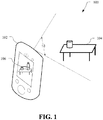
- System 100 includes a computing device 102, such as a mobile device.
- the mobile device may be any portable computing device with an input sensory unit, such as a camera, and a display.
- the computing device 102 may be a mobile device, such as a smart phone, although the functionality described herein is not limited to smart phones.
- the computing device 102 may be any portable or mobile device such as a digital camera, a camcorder, a tablet computer, a personal digital assistant, a video game console, a head-mounted display (HMD) or other wearable display, a projector device, or other device.
- HMD head-mounted display
- a computing device 102 such as a personal computer (e.g., desktop computer), or other non-handheld device or device not typically labeled a mobile device, could be used.
- the computing device 102 may include a camera for capturing images of physical objects in the real-world physical environment.
- a cylinder e.g., can of soup
- table 104 e.g., a table 104.
- the computing device 102 may be configured to augment reality by capturing images of the physical environment, here capturing images of the table on which the can of soup is situated, and displaying the additional imagery on a transparent or semi- transparent display supplemented with one or more virtual objects.
- a three-dimensional character 106 is superimposed on the view of the physical environment, including table 104.
- Three-dimensional character 106 may be any form of virtual object and is not restricted to a humanoid character.
- Three-dimensional character 106 may be permitted to move to various locations on an AR plane that has been constructed on the surface of table 104 as detailed herein.
- the AR plane may be constructed such that the can of soup is excluded from the AR plane, thus precluding three-dimensional character 106 from appearing to collide with the can of soup in the AR environment presented on the display of computing device 102.
- FIG. 2 illustrates an example physical scene 200, in accordance with certain embodiments of the present disclosure.
- the scene may include part of a table 210 (e.g., a flat surface).
- some physical objects 215 e.g., books, cups, toys, etc.
- the computing device 102 can capture one or more images and/or other data for feature point (e.g., SLAM) determination.
- the one or more images may be shown in real-time or near real-time on a display 230 of the computing device 102.
- the display 230 may also show AR graphics and/or other information overlaid on the one or more displayed images.
- the computing device 102 can comprise a tablet, smart phone, personal camera, and the like, and the one or more images may be images from a video feed captured by a camera of the computing device 102.
- Techniques can be performed by an application, such as an AR application, executed by the computing device 102 to determine the location, orientation, and dimensions of the planar surface using, for example, image processing and/or feature point information, and generate an augmented reality (AR) plane, that may be a reconstructed representation of the planar surface.
- AR augmented reality
- image target 217 can be an object with features known to the computing device 102, to help determine the features of the planar surface.
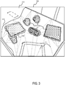
- FIG. 3 illustrates an example AR plane 310 that represents a portion of the physical scene illustrated in FIG. 2 .
- a table 210 e.g., a flat surface
- the triangular mesh 315 represents the planar surface that is identified by the proposed method.
- the boundaries (or borders) of the represented AR plane 310 may grow over time by analyzing more portions (e.g., cells) and adding them to the identified portion of the planar surface. This usually happens when more areas of the planar surface become visible due to a new viewpoint.
- the borders of the representation of the AR plane 310 do not yet correctly indicate all of the physical borders of the planar surface 210.
- the representation can continue to be improved and refined with the availability of additional information (e.g., images at different angles).
- lines 315 are shown to help illustrate the AR plane 310. It can be noted that the AR plane 310 includes a large number of lines 315, although only two are labeled.
- the AR plane 310 can not only indicate where borders of a planar surface 210 may be, but also can include "holes" 320 where portions of the planar surface 210 are occluded. For object-detection purposes, these holes 320 can indicate the presence of objects 215.
- the holes 320 cast by an objects 215 e.g. due to plane sweeping, plane extension using statistical information
- the objects 215 will occlude some portion of the planar surface 210 behind the object.
- FIG. 15A helps illustrate this phenomenon in further detail.
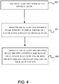
- FIG. 4 is a flow diagram for a method to be performed by a computing device for creating a digital representation of a physical scene, in accordance with certain embodiments of the present disclosure.
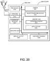
- any and/or all of the methods and/or method steps described herein may be implemented by and/or in a computing device 102, such as the mobile device and/or the device described in greater detail in FIG. 20 , for instance.
- one or more of the operations described below with respect to FIG. 4 are implemented by a processor of the computing device 2000, such as the processor 2010 or another processor.
- any and/or all of the methods and/or method steps described herein may be implemented in computer-readable instructions, such as computer-readable instructions stored on a computer-readable medium such as the memory 2020, storage or another computer-readable medium.
- the computing device may obtain at least one image of the physical scene.
- the device may have a camera to capture one or more images.
- the device may receive an image that is taken from the scene.
- the device may identify an initial portion of a planar surface within the physical scene.
- the device may identify an object that is used as an initialization target (e.g., a 2-dimensional surface such as a piece of paper with a known graphic printed thereon, a cylinder, or any other object that is known in advance).
- an initialization target is discussed herein, other techniques may be used for detecting the initial portion of the planer surface without deviating from the scope of the invention.
- one or more objects placed on a surface may be detected using feature detection for the objects. In scenarios where the base of one or more objects are coplanar with a portion of a surface, that portion of the surface may be indicate an initial portion of a planar surface.
- an initialization object e.g., object 217 in FIG. 2
- an initialization object provides a way for the system to quickly establish the position of the plane in question.
- Example of an initialization object is illustrated by object 217 in FIG. 2 .
- Useful assumptions may be made regarding the plane using the initialization object. For example, for horizontal planes, one assumption may be that the plane is perpendicular to the direction of gravity. It should be noted that if an initialization target is part of the scene, a direct relationship between the camera and the plane can be deduced without the need to assume direction of gravity. On the other hand, if the plane is estimated without initialization target, some assumptions such as direction of gravity may be used, since there might be other dominant planes in the scene (e.g., walls).
- Another assumption may be that, since the initialization object is resting on the surface, the bottom surface of the initialization object is co-planar with the plane. Based on assumptions such as these, a model of the plane may be constructed and position of camera relative to the plane may be found.
- a planar surface corresponding to the real world object e.g., a table
- the table is co-planar with the AR plane that has been constructed. What is not known is how far the table extends in different directions within the model of the plane, in other words, where are the edges of the table.
- the techniques described herein describe how to successively identify additional portions of a planar surface (e.g., table) and provide an efficient way of determining the actual extent of such a model of the planar surface using one or more visual images.
- a point cloud is a set of data points that can be represented in a coordinate system. For example, in a three-dimensional coordinate system, these points can be defined by X, Y, and Z coordinates. Point clouds often are intended to represent the external surface of an object.
- one or more point clouds may be generated as an output of a SLAM (Simultaneous localization and mapping) system.
- the point clouds may be generated by a depth sensor (e.g., that could be part of a camera).
- the device may identify additional portions of the planar surface.
- each of the additional portions is identified as being a part of the planar surface based on determining a likeness between at least one visual or geometric property associated with the additional portion with at least one corresponding visual property associated with one or more portions already identified to be part of the planar surface.
- the visual property used may be a set of red-green-blue (RGB) values, which may be a better indication of whether a portion in question is in fact a part of a larger planar surface (e.g., a table).
- RGB red-green-blue
- the RGB value e.g., the table top is a particular hue of purple
- the additional portions of the planar surface may be identified by establishing an AR planar region within which the planar surface resides.
- the AR planar region may be partitioned into a plurality of cells. Each cell may be evaluated as a potential additional portion of the planar surface.
- the cells may be evaluated iteratively. For example, for each cell that is identified as an additional portion of the planar surface, neighboring cells are identified. In one embodiment, for each neighboring cell that is not already identified as part of the planar surface, the cell may be evaluated as a potential portion of the planar surface. If the neighboring cell has similar characteristics as the characteristics of other cells in the planar surface, the cell may be added to the AR plane. If the neighboring cell does not have similar characteristics, the cell may be identified as not being part of the AR plane. The iterative process can be repeated until no more new, additional portions of the planar surface can be found, or some other termination condition is reached.
- the at least one visual property of all the cells already identified as part of the planar surface may be averaged or combined in some other way to establish a baseline.
- the at least one visual property of just some of the cells e.g., only cells in proximity
- the at least one visual property of the candidate cell may be evaluated to determine a measure of "likeness" to the baseline. If the measure of likeness is above a predetermined threshold, the candidate cell may be identified as being a part of the AR plane. Otherwise, the candidate cell may be identified as not being a part of the AR plane.
- the computing device 102 may obtain a plurality of images and improve the planar representation by using information in the images. For example, the computing device 102 may move from one location to another location and capture one or more images of the scene from different angles. The computing device 102 may dynamically update/improve the planar representation over time by using information from newer images. In one embodiment, the planar representation of the scene may be generated in real-time as the user moves in an area.
- the proposed method may be used to process images that are taken using a camera, similar to the camera 2021 discussed in FIG. 20 .
- the images may be taken with depth cameras (e.g., cameras which include a depth sensor) and be processed to generate the planar representation.
- depth cameras e.g., cameras which include a depth sensor
- any kind of cameras or image sensor may be used in the proposed system without departing from teachings herein.
- a depth sensor provides a range image where each pixel represents the distance to the camera.
- the pixels can be easily converted to a three dimensional (3-D) point cloud.
- Multiple range images can be combined for covering a larger part of a 3-D space. If information about position and orientation of a plane is available (note that the boundaries can be unknown,) 3-D points that are located in the plane can be identified. The 3-D points can be projected onto the plane and thus be further investigated only in the 2-D space of the plane.
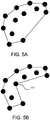
- a convex hull (as illustrated in FIG. 5A ) may be calculated.
- the convex hull or convex envelope of a set X of points in the Euclidean plane or Euclidean space is the smallest convex set that contains X.
- the convex hull may be visualized as the shape formed by a rubber band stretched around X.
- the convex hull may further be refined (as illustrated by FIG. 5B ) by adding additional points to the boundary.
- the convex hull is further refined by adding point 502 to the shape.
- the boundary may iteratively be refined in areas where a large empty space is enclosed by the boundary.
- the plane boundaries based on nearby 3-D points to the plane boundaries, it is possible to find out whether the surrounding surface of a boundary is below or above the plane.
- the boundaries can be labeled accordingly as upwards or downwards.
- FIG. 6 illustrates an embodiment of a system 600 that may be used to construct a AR plane.
- a navigational mesh or a "navmesh" derived in an Augmented Reality system may also be referred to as an AR plane.
- the AR plane may also be referred to as a navigational mesh or navmesh while describing a Augmented Reality system.
- System 600 may be implemented using the system of FIG. 20 or some other computerized system.
- Each module of system 600 may be implemented using software, firmware, and/or hardware. For instance, one or more general purpose processors 2010 and/or specialized processors may perform the functions of some or all of the modules of system 600.
- SLAM process engine 610 may be configured to use a SLAM process to create a point cloud of reference points based on physical objects present in images of a physical environment captured by a camera. SLAM process engine 610 may cause capturing of an image and may identify various reference points within that image. A second image may be caused to be captured by SLAM process engine 610. The second image may be captured from a different location than the first image. The direction and/or distance between capture of the first and second image may be determined by SLAM process engine 610, by determining the relative positioning of the camera at the time of obtaining the first and second image and a reference point common amongst the two images. For example, at least some of the same reference points within the first image may be identified within the second image.
- SLAM process engine 610 may determine the depth of at least some of the corresponding reference points present within the first and second images. Multiple additional images may be captured, have reference points identified, and depth values calculated for the physical environment. Therefore, the SLAM process may involve the use of more than two images and may calculate and refine three-dimensional positions for various reference points throughout the physical environment. SLAM process engine 610 may output a point cloud that includes multiple points, each having three-dimensional coordinates (that is, including a depth value). Each of these points may correspond to a reference point present in each of the at least two images captured using the camera (or other form of image capture device).
- some other form of three dimensional mapping process may be used to create a point cloud.
- images that include depth information for example images captured using a time-of-flight analysis or a stereoscopic camera system, may be used to generate a point cloud for the physical environment.
- FIG. 7 represents an example of a captured image identifying various reference points as part of a point cloud.
- SLAM process engine 610 that may identify various reference points. Each point illustrated in FIG. 7 may represent a reference point for which a depth value was calculated by SLAM process engine 610 based on at least two analyzed images. For example, reference point 710-1 corresponds to the edge of the placemat on the table and reference point 710-2 corresponds to an edge of the facial tissue box. Each of these points may have a depth value.
- SLAM process engine 610 may be used to determine the point cloud (such as the point cloud of FIG. 7 ), other arrangements may be employed. For instance, a camera capable of measuring depth, such as a stereo camera system or time-of-flight camera system may be used in place of (or to augment) SLAM process engine 610. SLAM process engine 610 may allow for determining depth information without additional hardware being needed besides conventional hardware of the computing device 102, including a conventional two-dimensional camera and movement-sensing hardware, such as a gyroscope and/or accelerometer. In one instance, the gyroscope and/or the accelerometer may further aid in determining the change in distance/orientation of the camera with respect to the physical scene (or object in the scene).
- the point cloud output by SLAM process engine 610 may include some number of approximately coplanar reference points that are used to map a ground plane by surface mapping engine 620.
- at least one surface may be present, such as a table top, floor, the ground, etc.
- a plane with the largest number of coplanar reference points may be used as the ground plane.
- AR objects placed on the ground plane are intended to appear as if sitting on top of the physical surface that is serving as the ground plane.
- the outer reference points that were determined to fall on the plane that is to serve as the ground plane may be connected to form the outer limits of the ground plane.
- the ground plane may be extended by further mapping of the surface via additional processes, including mapping the surface based on color.
- the ground plane is selected by the user as input to surface mapping engine 620. For instance, in a captured image, a user may select the surface to use as the ground plane. Otherwise, the ground plane may be found by fitting a plane to as many reference points as possible by surface mapping engine 620.
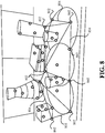
- FIG. 8 illustrates a visual example of a ground plane fit to reference points determined to be coplanar. The reference points fitted to the ground plane are indicated by 802. The lines 804 between the reference points 802 may represent the outer extent of the ground plane.
- Each cell may be a polygon that falls entirely within the ground plane.
- the polygons created may be three or four sides and may all be coplanar with the ground plane. Vertices of polygons may be reference points that define the extent of the ground plane.
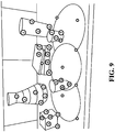
- Point cloud clustering engine 630 may cluster reference points according to what object the reference points are determined to be part of. Reference points determined to be part of the ground plane may be excluded from analysis by point cloud clustering engine 630. Reference points determined to belong to a same object, such as based on location, depth, identified boundaries and/or color properties may be clustered together. Referring to FIG. 9 , the reference points indicated by the different letters from the English alphabet (a, b, c, d, e f) of the point cloud represent points that have been clustered together.
- Letter 'a' reference points correspond to the tissue box; letter 'b' reference points correspond to the tall cup; letter 'c' reference points correspond to the woven vessel; letter 'd' reference points correspond to the books; green reference points correspond to the small cup; letter 'e' reference points correspond to the candle; and the unmarked reference points correspond to the table's surface.
- Object modeling engine 640 may serve to model physical objects that were identified based on clustered reference points by point cloud clustering engine 630.
- Object modeling engine 640 may use simplified geometric shapes to model the objects identified based on clustered reference points by point cloud clustering engine 630. For instance, referring to FIG. 10 , six-sided three-dimensional geometric shapes may be used to model each physical object. Alternatively, more complex geometry may be used to create more accurate geometric models of the identified objects.
- Each geometric model may be associated with a location such that each geometric model is placed in reference to the ground plane created by surface mapping engine 620. Each geometric model may be used to determine locations where virtual objects should not be placed to help maintain realism in the AR environment.
- color information and/or determined shape information can be used from the observed silhouettes of the physical objects to define and/or refine the associated geometric models.
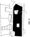
- AR plane construction engine 650 may create a AR plane (black surface) using the ground plane determined by surface mapping engine 620 and the physical object models determined by object modeling engine 640.
- FIG. 11 illustrates an embodiment of an AR plane (black solid surface indicated by 1102) that is created based on the ground plane of FIG. 8 and the modeled objects of FIG. 10 .
- Creation of the AR plane may include clipping (or otherwise removing) from the ground plane portions of the ground plane that intersect with or contact the modeled objects. This may involve reducing the extent of the ground plane and/or removing one or more regions from the ground plane to create the AR plane.
- Creation of the AR plane may involve cells of the ground plane being subdivided to avoid modeled objects (e.g., one or more subdivsions of the cell may be maintained as a cell in the AR plane, and one or more subdivisions of the cell may be excluded from the AR plane because it overlaps or contacts a modeled object. Vertices of the new cells may or may not correspond to reference points from the point cloud that were previously identified as part of the ground plane. For a cell to be part of the AR plane, the cell may be required to be distinct from any overlapping object identified by object modeling engine 640. Therefore, from within a cell of the AR plane, a straight line to any other point on the cell may be drawn without intersecting a modeled object. "Holes,” indicated by 1104 in FIG. 11 , within the AR plane exist where modeled physical objects are located. The AR plane does not include such regions that correspond to modeled physical objects.
- AR plane implementation application 660 may represent an application that uses the AR plane created by AR plane construction engine 650.
- AR plane implementation application 660 may receive coordinates of the cells of the AR plane that can be superimposed on images captured of the physical environment. Therefore, the AR plane received by AR plane implementation application 660 is based on the real-world, physical environment on which AR plane implementation application 660 is going to position or move one or more virtual objects without colliding with physical objects present in the environment.
- the AR plane may be positioned such that it appears to be placed on a surface present in the physical environment, such as a tabletop.
- AR plane implementation application 660 may permit manipulation of three dimensional virtual objects on the AR plane determined by AR plane construction engine 650.
- AR plane implementation application 660 may use the AR plane for path planning, such as to determine how a virtual object should move among cells of the AR plane without colliding with a modeled physical object.
- AR plane implementation application 660 may be configured such that virtual objects, when remaining within a cell of the AR plane, can be moved in a straight line in any direction without colliding with a modeled physical object. Edges of the AR plane may serve as the limit of where virtual objects can be placed or move.
- AR plane implementation application 660 may receive modeling information for the objects.
- This modeling information may be the geometric models for objects determined by object modeling engine 640. This modeling information may include height information for the objects. While the AR plane may ensure that a virtual object does not collide with the virtual object, the modeling information provided to AR plane implementation application 660 may allow for virtual objects to be hidden from view when on the AR plane behind a modeled physical object. Additionally, virtual information (e.g., graphics) may be overlaid one or more of the modeled objects to augment or change the appearance of the physical objects in the AR environment. For instance, the small cup may be made to appear as a house in the AR environment.
- edges of the AR plane are assigned properties, such as "wall edge” or "cliff edge” which can be result in different handling by AR plane implementation application 660.
- a wall edge may represent an edge of the AR plane where an obstacle exists that prevents a virtual object from being moved farther (e.g., a wall, a large object);
- a cliff edge may represent an edge of the AR plane where an edge exists from which a virtual object could fall (e.g., a table edge).
- FIG. 12 illustrates the geometric models 1202 of the physical objects created and located by object modeling engine 640 in conjunction with the AR plane created by AR plane construction engine 650. The information for the AR plane and the geometric models of the physical objects may be output to AR implementation application 660.
- FIG. 13 illustrates an embodiment of a method 1300 for creating a AR plane.
- Method 1300 may be performed by the computing device of FIG. 20 or by some other system configured to present analyze a physical environment.
- a physical environment may be analyzed.
- the physical environment may include one or more physical objects and at least one surface on which virtual objects are desired to be placed.
- Block 1310 may include capturing and analyzing one or more images of the physical environment.
- an AR plane may be created based upon the analysis of block 1310.
- the AR plane may include multiple cells. Each cell may have three or four sides.
- a virtual object is known to not collide with any of the physical objects present in the AR environment.
- the virtual object may move in a straight line in any direction along the plane of the AR plane and not collide with any of the physical objects in the AR environment, since the AR plane comprises holes for physical objects, as described previously.
- the AR plane created at block 1320 may be output in form of coordinates of the various cells of the AR plane.
- the AR plane may be linked with a reference point of an image of the physical environment.
- FIG. 14 illustrates an embodiment of a method 1400 for creating and using an AR plane.
- Method 1400 may be performed by the system and/or computing device of FIGS. 20 or by some other system configured to present analyze a physical environment.
- Means for performing the steps of method 1400 include one or more instances of the components of the computing device of FIG. 20 .
- Method 1400 may represent a more detailed embodiment of method 1300 of FIG. 13 .
- multiple images of a physical environment may be captured.
- the one or more images may be captured using camera 2021 ( FIG. 20 ).
- the physical environment may also include one or more physical objects, which when represented in an AR environment, are not permitted to collide with a virtual object.
- An amount of movement of the camera used to capture the multiple images may be measured as part of block 1410.
- a SLAM process may be performed.
- the SLAM process may create a point cloud of reference points based on physical objects present in one or more of the images of the physical environment captured by a camera.
- the SLAM process may identify various reference points within each image. At least some of the same reference points may be identified in at least two of the multiple captured images.
- the SLAM process may determine the depth of at least some of the reference points present within the images.
- the SLAM process may result in a point cloud that includes multiple points, each having three-dimensional coordinates (including a depth value). Each of these points may correspond to a reference point present in at least two of the multiple captured images (from the camera or other form of image capture device).
- the point cloud representing the physical environment may be created using a modeling process other than a SLAM process, such as other forms of three-dimensional mapping processes, without deviating from the scope of the invention.
- a ground plane may be determined using reference points from the point cloud.
- the point cloud output by block 1420 may have at least some approximately coplanar reference points that are used to create a ground plane.
- at least one surface such as a table top, floor, the ground, etc.
- the largest cluster of reference points to which a plane can be fit (within a predefined margin of error) may be used to define a ground plane.
- the ground plane may be automatically selected to serve as the surface of the AR plane. As such, AR objects placed on the ground plane are intended to appear as if sitting on top of the physical surface that is serving as the ground plane.
- the ground plane may be extended by further mapping of the surface via additional processes, including mapping the surface based on color.
- the ground plane may be selected by the user via user input. For instance, in a captured image, a user may select the surface to be used as the ground plane by providing input through a user interface (not shown), such as highlighting portions of the surface using a touchpad or stylus on the screen of the mobile device.
- the created ground plane may contain multiple cells based on the outlying vertices of the ground plane. Each cell of the ground plane may be a polygon that falls entirely within the ground plane. In some embodiments, the polygons created may be three or four sides and may all be coplanar with the ground plane.
- reference points that were not determined to be part of the ground plane may be grouped into one or more clusters.
- Reference points may be clustered according to what object the reference points are determined to be part of.
- the clustering of the reference points not part of the ground plane may be performed using a variety of different criteria, such as based on spatial proximity of points, color associated with the reference points.
- Reference points determined to belong to a same object, such as based on location, depth, identified boundaries and/or color properties may be clustered together. As such, the number of clusters may be dependent on the number of physical objects in the imaged physical environment.
- physical objects of the physical environment may be modeled based upon the clusters identified at block 1440.
- Simplified geometric models may be used to model the objects identified based on clustered reference points. More complex geometry may be used to create more accurate geometric models of the identified physical objects.
- Each geometric model may be associated with a location such that each geometric model is placed in reference to the ground plane.
- Each geometric model may be used to determine locations where virtual objects should not be placed to help maintain realism in the AR environment.
- an AR plane may be created using the ground plane from block 1430 and the models of the physical objects from block 1450. Creation of the AR plane may include clipping (or otherwise removing) from the ground plane portions of the ground plane that intersect with the modeled physical objects. This may involve reducing the extent of the ground plane and/or creating one or more holes in the ground plane to create the AR plane.. For a cell to be part of the AR plane, the cell may be required to be completely separate from any overlapping modeled physical object. Therefore, from within a cell of the AR plane, a straight line to any other point on the same cell may be drawn without intersecting a modeled object. "Holes" within the AR plane can exist where modeled physical objects are determined to be located.
- the AR plane may be optionally provided to an application and used by the application for manipulating virtual objects in the AR environment.
- the AR plane may be output in the form of coordinates that define the cells of the AR plane. Therefore, the AR plane output may be based on the real-world, physical environment on which one or more virtual objects are to be positioned or moved in an AR environment without giving the appearance of collision with physical objects in the physical environment.
- the AR plane may be positioned such that it appears to be placed on a surface present in the physical environment, such as a tabletop.
- the AR plane may be used by an application for path planning, such as to determine how a virtual object can be moved among cells of the AR plane without colliding with a modeled physical object in the AR environment.
- Virtual objects when remaining within a cell of the AR plane, can be moved in a straight line in any direction without colliding with a modeled physical object.
- Edges of the AR plane may serve as the limit of where virtual objects can be placed or move. Therefore, within the application, the AR plane may be used to restrict movement of virtual objects within the AR environment so that the virtual objects do not appear to collide with physical objects of the physical environment on which the AR environment is superimposed.
- the AR plane may be used to determine where non-player characters (which may be virtual objects) can move without appearing to collide with physical objects in the AR environment. For instance, non-player characters may move towards the player's character while remaining on the AR plane (and thus avoiding the appearance of collision with physical objects). As long as the game can interpret the provided AR plane such that non-player characters remain on the AR plane, the game may not need to interpret the actual physical environment while still giving the appearance of avoiding physical objects that are present in the AR environment.
- the AR plane may also be used to restrict the position and location of player motion, such as a character controlled by a user in an application that permits three-dimensional movement.
- Virtual objects within the application may similarly be limited in movement by the AR plane.
- Virtual objects, a player's character, and non-player characters may be represented by a single three-dimensional bounding box (or a more detailed polygon mesh) with the bounding box maintained on the AR plane.
- a AR plane may be useful in an AR environment. For example, modeling how an object looks in a particular physical environment, such as a coffee machine (virtual object) that the user is thinking of purchasing in the user's kitchen, or a new car in the user's garage.
- the AR plane may be used for manipulating the virtual object while avoiding physical objects in the AR environment. Therefore, the coffee machine would not be allowed to be placed in collision with a blender (a physical object) on the user's kitchen counter, but could be placed on an empty spot on the user's kitchen counter that is available for movement according to a created AR plane.
- modeling information for the one or more physical objects may be output.
- This modeling information may be the geometric models for objects determined at block 1450.
- This modeling information may include height information for the objects.
- the AR plane may ensure that a virtual object does not collide with the virtual object, the modeling information may allow for virtual objects to be hidden (or otherwise modified for display) when present on the AR plane in the AR environment behind a modeled physical object.
- virtual information e.g., graphics
- FIG. 15A illustrates a hole 1510-A from FIG.
- the computing device 102 (not shown) would be located on the opposite side of the object as the second portion 1520-A.)
- the second portion 1520-A is therefore due to a projection, or "shadow,” of the object 215, which, from the perspective of the computing device 102 when the one or more images are captured, occludes a portion of the planar surface 210 behind the object 215.
- FIG. 15B illustrates a modified hole 1510-B (shaded region) in which the second portion 1520 -B has been reduced or removed (as indicated by the line and arrows) to a smaller size.
- techniques can utilize not only information regarding the planar surface itself, but also feature point information (which can be provided by SLAM) to intelligently estimate the dimensions for the reduced second portion 1520-B.
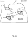
- FIG. 16 is a simplified fronto-parallel view of an AR plane 310 of a planar surface according to one embodiment.
- the AR plane 310 has holes 320, due to occlusions caused by objects on the planar surface.
- the holes 320 further include portions 1615 projected onto the AR plane 310 away from the camera viewing direction due to the perspective of the camera.
- the darkened outlines 1610 surrounding the objects 215 represent estimations of the shapes of the objects 215 that can be achieved from the techniques provided herein.
- Information about the objects 215 not only can be gleaned from the AR plane 310, but also from SLAM and/or other techniques providing feature points of the objects 215.
- Feature points can be points on an external surface of the objects 215 about which location information is gathered. Such information can, for example, indicate the height of the feature point above the AR plane 310 of the planar surface, as well as a distance to the front (or other edge) of a hole 220.
- the "front of a hole” is the closest portion of the planar surface, from the perspective of at least one captured image of the camera, occluded in the at least one captured image by the object.
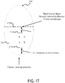
- FIG. 17 is a simplified fronto-parallel view of a hole 320 in a dense AR plane 310 of a planar surface, illustrating an example of how the geometry of a portion of an object can be estimated.
- a closest feature point 1710-1 of the object (from the perspective of the camera viewing direction) is determined, and a distance D from the closest feature point 1710-1 to the front of the hole 320 is determined.
- the back of the hole can then be estimated as a plane that extends back-using the same distance D-from the farthest feature point 1710-2 to a plane 1720.
- the estimated footprint of the object 215 is far smaller than the hole 320 because the portion of the object 215 that is not visible is now estimated to extend back only to the plane 1720 rather than the back of the hole 320. Accordingly, a representation of the object 215 can be generated in which the unseen portion of the object 215 extends back only to the plane 1720.
- An extension would be to estimate a curved/spline-based back-surface representation based on distance metrics of the front face to the feature points 1710-1.
- embodiments can employ additional or alternative algorithms to estimate the geometry of the portion of the object 215 not visible in one or more images captured by a mobile device.
- the estimated geometry does not need to be planar, but instead can be curved or given other features.
- a two-dimensional midpoint of the feature points of an object, in a fronto-parallel view can be calculated (using, for example, x and y coordinates in a plane of planar surface), and the feature points can be "flipped" around the midpoint (e.g., by rotating 180 around the midpoint or by providing a mirror image of the feature points, reflected on a plane parallel to the cameral viewing direction that includes the midpoint), thereby creating a reflected symmetrical object representation.
- the midpoint can be calculated, and the back face of the object can be estimated as a curved surface having the radius given by the distance of the midpoint to the front of the hole.
- the estimated back surface then, is cylindrical in shape.
- Other algorithms may include variance in the back surface as a function of height above the planar surface. Where an estimation provides a footprint that may be larger than the hole itself (i.e., it would occlude a visible portion of the planar surface), it can be truncated by the bounds of the hole.
- an object representation can be formed by extruding the object in the direction normal to the plane surface.
- the height of the extrusion can be bounded by several pieces of information, including: (1) The silhouette of the object in an image. If there are images where the object silhouette falls against the plane due to camera angle, this silhouette can give a maximum bound for the height of the object.
- a reasonable representation of an object may be inferred by observing the silhouette for the object in the rectified image in multiple views against the plane. In some instances, this may be referred to as space carving.
- the silhouette of the object can be inferred by observing the boundary of the object against the plane, and using the boundary to carve away areas that are not the object.
- this may be used to bound the height.
- an accurate representation of an object, rather than just an excluded hole may be detected by performing space carving.
- Point features can further be utilized to estimate the shape of the top of the object. For example, some embodiments may use the highest feature points to bound the extruded height of the object. Additionally or alternatively, a variable-height surface to the extruded shape can be based on the heights of feature-points in the hole, e.g. using a spline representation or piecewise planar representation.
- the AR plane 310 may still be refined during the object reconstruction process. As the camera is moving around and the plane representation is refined, holes may appear in the representation. An object lying on top of the plane is likely to occupy some portion of the hole in the plane. Additionally, the height of the object is not known exactly (the silhouette of the object in different frames does provide constraints).
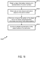
- FIG. 18 illustrates an embodiment of a method 1800 for constructing a digital representation of an object on a planar surface of a physical scene.
- Means for performing one or more of the components of the method 1800 can include hardware and/or software means described in further detail in relation to FIG. 20 .
- Alternative embodiments may include alterations to the embodiments shown.
- Components of the method 1800, although illustrated in a particular order, may be performed in a different order and/or simultaneously, according to different embodiments.
- a person of ordinary skill in the art will recognize many additions, omissions, and/or other variations.
- the method 1800 can be executed by hardware and/or software at an operating system- or device-level.
- Representations of the planar surface (i.e., the AR plane) and/or objects can then be provided to an AR, CV, or other application executed by the mobile device.
- the representations can be provided in any of a variety of standardized and/or proprietary formats (e.g., mesh (triangles and/or polygons in 3D space), etc.).
- the representations can be provided in substantially real time or near-real time, so that an AR application is able to display an AR environment while images of a physical scene are being captured by a mobile device.
- surface information indicative of a representation of a planar surface is obtained.
- surface information can be based on at least one captured image of a physical scene.
- Techniques described with reference to FIGs. 13 , 14 and any other figure described earlier may be used for deriving an AR plane using surface information.
- the representation can be, for example, a dense plane representation obtained using any of a variety of algorithms for defining the plane from image information. These algorithms may be executed by the same application-or a different application-than an application executing the method 1800 of FIG. 18 .
- Block 1820 includes obtaining one or more feature points of an object on the planar surface.
- Feature points can include information indicative of a location of a point on an external surface of the object in a 3D space (e.g., relative to the planar surface). These feature points can be derived, for example from a point-cloud representation of the object provided by SLAM.
- a shape of the portion of the object that is not visible is estimated using the surface information and the one or more feature points.
- any of a variety of algorithms may be used to estimate a back face of the object. These algorithms can combine feature point information (e.g., height, depth, etc.) with surface information (e.g., hole locations, dimensions, etc.) to provide the estimation.
- the estimation may further include transforming the surface information and the one or more feature points to a fronto-parallel perspective of the planar surface.
- pose information regarding the one or more images may be used in transforming the surface information and the one or more feature points to a fronto-parallel perspective of the planar surface.
- Estimations may further include determining a highest (relative to the planar surface) and/or nearest (from the perspective of the one or more captured images) feature point of an object.
- Estimations may include a particular shape.
- the estimation may represent the back face of the object in a spline, curved, and/or planar representation.
- a digital representation of the object is constructed, based on the estimation.
- the digital representation can include the representation of the estimated (i.e., unseen) portion of the object, as well as visible portions of the object.
- the digital representation then, can incorporate feature points to provide a geometric shape to visible portions of the object.
- the representation can then be sent to and/or utilized by a CV application.
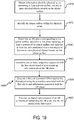
- FIG. 19 illustrates an embodiment of a method 1900 for constructing a digital representation of an object on a planar surface of a physical scene.
- Means for performing one or more of the components of the method 1900 can include hardware and/or software means described in further detail in relation to FIG. 20 .
- Alternative embodiments may include alterations to the embodiments shown.
- Components of the method 1900, although illustrated in a particular order, may be performed in a different order and/or simultaneously, according to different embodiments.
- a person of ordinary skill in the art will recognize many additions, omissions, and/or other variations.
- the method 1900, and other techniques described herein, can be executed by hardware and/or software at an operating system- or device-level.
- Representations of the planar surface (i.e., the AR plane) and/or objects can then be provided to an AR, CV, or other application executed by the mobile device.
- the representations can be provided in any of a variety of standardized and/or proprietary formats (e.g., mesh (triangles and/or polygons in 3D space), etc.).
- the representations can be provided in substantially real time or near-real time, so that an AR application is able to display an AR environment while images of a physical scene are being captured by a mobile device.
- components of the computing device obtain information about the physical scene containing at least a planar surface and one or more physical objects located on the planar surface.
- a camera may capture information about the physical scene.
- the information may be either provided to the computing device or stored in a buffer on the computing device.
- components of the computing device identify the planar surface within the physical scene.
- components of the computing device determine an AR plane corresponding to the planar surface wherein the AR plane comprises at least a portion of the planar surface and encircles at least one hole associated with a first object of the one or more physical objects located on the planar surface.
- the AR plane comprises a plurality of cells, each cell of the plurality of cells representing a region wherein a virtual object can navigate without collision with the first object.
- determining an AR plane corresponding to the planar surface may include analyzing at least two images of the physical scene comprising the first object, and based upon analysis of the at least two images of the physical scene, creating the AR plane such that the AR plane corresponds to the physical scene and excludes at least one region corresponding to the first object.
- analyzing the at least two images of the physical scene may include capturing, using a camera, a first image of the physical scene at a first location, wherein the first image includes the first object, determining a distance that the camera has moved from the first location to a second location, capturing, using the camera, a second image of the physical scene at the second location, wherein the second image includes the first object, and determining depth information for the first object using the first image and the second image.
- determining the AR plane corresponding to the planar surface may include identifying an initial portion of the planar surface within the physical scene, and identifying additional portions of the planar surface, wherein each of the additional portions is identified as being a part of the planar surface based on determining a likeness between at least one visual or geometric property associated with the additional portions with at least one corresponding visual or geometric property associated with one or more portions already identified to be part of the planar surface.
- identifying the additional portions of the planar surface may include establishing a model of a planar region within which the planar surface resides, partitioning the planar region into a plurality of cells, and evaluating each cell as a potential additional portion of the planar surface.
- evaluating each cell comprises iterating step for each cell identified as an additional portion of the planar surface, identifying neighboring cells not already identified as part of the planar surface, and for each identified neighboring cell, evaluating the neighboring cell as a potential portion of the planar surface.
- components of the computing device determine one or more properties associated with the first object based at least in part on information about the AR plane. In certain embodiments, determining one or more properties associated with the first object may be further based on identifying at least one or more feature points. In certain embodiments, one or more properties associated with the first object may include identifying one or more regions in the planar surface, wherein the one or more regions correspond to location of the first object on the planar surface, and determining one or more external surfaces of the first object based on location of one or more convex regions and the one or more feature points. However, other techniques may be used without deviating from the scope of the invention. In some embodiments, constructing the digital representation of the first object may include extruding object in a direction normal to the planar surface, based on a shape of a portion of the planar surface occluded by the first object.
- components of the computing device generate a three-dimensional (3D) model of the first object using the properties associated with the first object and information associated with the AR plane.
- generating the 3D model of the first object may include obtaining one or more feature points of the first object, wherein each feature point of the one or more feature points is indicative of a location, relative to the planar surface, of a point on an external surface of the first object, estimating, using information associated with the planar surface and the one or more feature points, a shape of a portion of the first object that is not visible, and constructing the 3D reconstructed object, based on the estimation.
- estimating a shape of a portion of the first object that is not visible may include using one or more representation techniques, such as a spline representation, a reflected symmetrical object representation, a planar representation, or a curved representation. Techniques described with reference to FIGs. 15A-B , 16 , 17 and any other figure described earlier may be used for generating a a three-dimensional (3D) model of the first object.
- representation techniques such as a spline representation, a reflected symmetrical object representation, a planar representation, or a curved representation.
- components of the computing device generate a digital representation of an AR environment comprising the AR plane and the 3D model of the first object.
- FIG. 20 describes one potential implementation of a device which may be used to represent scenes, according to certain embodiments.
- device 102 as described in FIG. 1 may be implemented with the specifically described details of process 300.
- specialized modules such as camera 2021 and image processing module 2022 may include functionality needed to capture and process images using the proposed method.
- the camera 2021 and image processing modules 2022 may be implemented to interact with various other modules of device 2000.
- the combined image may be output on display output 2003.
- the image processing module may be controlled via user inputs from user input module 2006.
- User input module 2006 may accept inputs to define a user preferences regarding the represented scene or identify an initialization target in the scene.
- Memory 2020 may be configured to store images, and may also store settings and instructions that determine how the camera and the device operate.
- the device may be a mobile device and include processor 2010 configured to execute instructions for performing operations at a number of components and can be, for example, a general-purpose processor or microprocessor suitable for implementation within a portable electronic device.
- Processor 2010 may thus implement any or all of the specific steps for operating a camera and image processing module as described herein.
- Processor 2010 is communicatively coupled with a plurality of components within mobile device 2000. To realize this communicative coupling, processor 2010 may communicate with the other illustrated components across a bus 2060.
- Bus 2060 can be any subsystem adapted to transfer data within mobile device 2000.
- Bus 2060 can be a plurality of computer buses and include additional circuitry to transfer data.
- Memory 2020 may be coupled to processor 2010.
- memory 2020 offers both short-term and long-term storage and may in fact be divided into several units.
- Short term memory may store images which may be discarded after an analysis, or all images may be stored in long term storage depending on user selections.
- Memory 2020 may be volatile, such as static random access memory (SRAM) and/or dynamic random access memory (DRAM) and/or non-volatile, such as read-only memory (ROM), flash memory, and the like.
- SRAM static random access memory
- DRAM dynamic random access memory
- ROM read-only memory
- memory 2020 can include removable storage devices, such as secure digital (SD) cards.
- SD secure digital
- memory 2020 provides storage of computer readable instructions, data structures, program modules, and other data for mobile device 2000.
- memory 2020 may be distributed into different hardware modules.
- memory 2020 stores a plurality of applications 2026.
- Applications 2026 contain particular instructions to be executed by processor 2010.
- other hardware modules may additionally execute certain applications or parts of applications.
- Memory 2020 may be used to store computer readable instructions for modules that implement scanning according to certain embodiments, and may also store compact object representations as part of a database.
- memory 2020 includes an operating system 2023.
- Operating system 2023 may be operable to initiate the execution of the instructions provided by application modules and/or manage other hardware modules as well as interfaces with communication modules which may use wireless transceiver 2012 and a link 2016.
- Operating system 2023 may be adapted to perform other operations across the components of mobile device 2000, including threading, resource management, data storage control and other similar functionality.
- mobile device 2000 includes a plurality of other hardware modules 2001.
- Each of the other hardware modules 2001 is a physical module within mobile device 2000.
- each of the hardware modules 2001 is permanently configured as a structure, a respective one of hardware modules may be temporarily configured to perform specific functions or temporarily activated.
- a sensor 2062 can be, for example, an accelerometer, a Wi-Fi transceiver, a satellite navigation system receiver (e.g., a GPS module), a pressure module, a temperature module, an audio output and/or input module (e.g., a microphone), a camera module, a proximity sensor, an alternate line service (ALS) module, a capacitive touch sensor, a near field communication (NFC) module, a Bluetooth transceiver, a cellular transceiver, a magnetometer, a gyroscope, an inertial sensor (e.g., a module the combines an accelerometer and a gyroscope), an ambient light sensor, a relative humidity sensor, or any other similar module operable to provide sensory output and/or receive sensory input.
- a satellite navigation system receiver e.g., a GPS module
- a pressure module e.g., a temperature module
- an audio output and/or input module e.g., a microphone
- one or more functions of the sensors 2062 may be implemented as hardware, software, or firmware. Further, as described herein, certain hardware modules such as the accelerometer, the GPS module, the gyroscope, the inertial sensor, or other such modules may be used in conjunction with the camera and image processing module to provide additional information. In certain embodiments, a user may use a user input module 2006 to select how to analyze the images.
- Device 2000 may include a component such as a wireless communication module which may integrate antenna 2016 and wireless transceiver 2012 with any other hardware, firmware, or software necessary for wireless communications.
- a wireless communication module may be configured to receive signals from various devices such as data sources via networks and access points such as a network access point.
- compact object representations may be communicated to server computers, other mobile devices, or other networked computing devices to be stored in a remote database and used by multiple other devices when the devices execute object recognition functionality
- mobile device 2000 may have a display output 2003 and a user input module 2006.
- Display output 2003 graphically presents information from mobile device 2000 to the user. This information may be derived from one or more application modules, one or more hardware modules, a combination thereof, or any other suitable means for resolving graphical content for the user (e.g., by operating system 2023).
- Display output 2003 can be liquid crystal display (LCD) technology, light emitting polymer display (LPD) technology, or some other display technology.
- display module 2003 is a capacitive or resistive touch screen and may be sensitive to haptic and/or tactile contact with a user.
- the display output 2003 can comprise a multi-touch-sensitive display. Display output 2003 may then be used to display any number of outputs associated with a camera 2021 or image processing module 2022, such as alerts, settings, thresholds, user interfaces, or other such controls.
- embodiments were described as processes which may be depicted in a flow with process arrows. Although each may describe the operations as a sequential process, many of the operations can be performed in parallel or concurrently. In addition, the order of the operations may be rearranged. A process may have additional steps not included in the figure.
- embodiments of the methods may be implemented by hardware, software, firmware, middleware, microcode, hardware description languages, or any combination thereof.
- the program code or code segments to perform the associated tasks may be stored in a computer-readable medium such as a storage medium. Processors may perform the associated tasks.
- the above elements may merely be a component of a larger system, wherein other rules may take precedence over or otherwise modify the application of various embodiments, and any number of steps may be undertaken before, during, or after the elements of any embodiment are implemented.
- the method as described herein may be implemented in software.
- the software may in general be stored in a non-transitory storage device (e.g., memory) and carried out by a processor (e.g., a general purpose processor, a digital signal processor, and the like.)
- a processor e.g., a general purpose processor, a digital signal processor, and the like.
- configurations may be described as a process which is depicted as a flow diagram or block diagram. Although each may describe the operations as a sequential process, many of the operations can be performed in parallel or concurrently. In addition, the order of the operations may be rearranged. A process may have additional steps not included in the figure.
- examples of the methods may be implemented by hardware, software, firmware, middleware, microcode, hardware description languages, or any combination thereof. When implemented in software, firmware, middleware, or microcode, the program code or code segments to perform the necessary tasks may be stored in a non-transitory computer-readable medium such as a storage medium. Processors may perform the described tasks.
Claims (15)
- Procédé de construction d'une représentation numérique d'une scène physique dans un environnement de réalité augmentée, AR, comprenant :l'obtention d'informations concernant la scène physique contenant au moins une surface plane et un ou plusieurs objets physiques situés sur la surface plane ;l'identification de la surface plane au sein de la scène physique ;la détermination d'un plan AR correspondant à la surface plane, dans lequel le plan AR comprend au moins une portion de la surface plane et encercle au moins un trou associé à un premier objet des un ou plusieurs objets physiques situés sur la surface plane, le trou étant projeté par le premier objet et étant plus grand que le premier objet et des objets virtuels étant limités en position sur le plan AR ;la détermination d'une ou plusieurs propriétés associées au premier objet sur la base au moins en partie d'informations concernant le plan AR ;la génération d'un modèle tridimensionnel (3D) du premier objet en utilisant les propriétés associées au premier objet et des informations associées au plan AR ;la génération d'une représentation numérique de l'environnement AR comprenant le plan AR et le modèle 3D du premier objet, etl'affichage, substantiellement en temps réel, de la représentation numérique de l'environnement AR sur un dispositif mobile tandis que des images de la scène physique sont capturées par le dispositif mobile.
- Procédé selon la revendication 1, dans lequel la détermination d'une ou plusieurs propriétés associées au premier objet est basée en outre sur l'identification d'au moins un ou plusieurs points caractéristiques.
- Procédé selon la revendication 1, dans lequel le plan AR comprend une pluralité de cellules, chacune de la pluralité de cellules représentant une région dans laquelle un objet virtuel peut naviguer sans collision avec le premier objet.
- Procédé selon la revendication 1, dans lequel la détermination d'une ou plusieurs propriétés associées au premier objet comprend :l'identification d'une ou plusieurs régions dans la surface plane, les une ou plusieurs régions correspondant à un emplacement du premier objet sur la surface plane ; etla détermination d'une ou plusieurs surfaces externes du premier objet sur la base d'un emplacement d'une ou plusieurs régions convexes et des un ou plusieurs points caractéristiques.
- Procédé selon la revendication 1, dans lequel la détermination d'un plan AR correspondant à la surface plane comprend :l'analyse d'au moins deux images de la scène physique comprenant le premier objet ; etsur la base de l'analyse des au moins deux images de la scène physique, la création du plan AR de manière que le plan AR corresponde à la scène physique et exclut au moins une région correspondant au premier objet.
- Procédé selon la revendication 5, dans lequel l'analyse des au moins deux images de la scène physique comprend :la capture, en utilisant une caméra, d'une première image de la scène physique au niveau d'un premier emplacement, la première image incluant le premier objet ;la détermination d'une distance de laquelle la caméra s'est déplacée du premier emplacement à un second emplacement ;la capture, en utilisant la caméra, d'une seconde image de la scène physique au niveau du second emplacement, la seconde image incluant le premier objet ; etla détermination d'informations de profondeur pour le premier objet en utilisant la première image et la seconde image.
- Procédé selon la revendication 1, dans lequel la génération du modèle 3D du premier objet comprend :l'obtention d'un ou plusieurs points caractéristiques du premier objet, chaque point caractéristique des un ou plusieurs points caractéristiques étant indicatif d'un emplacement, par rapport à la surface plane, d'un point sur une surface externe du premier objet ;l'estimation, en utilisant des informations associées au plan AR et aux un ou plusieurs points caractéristiques, d'une forme d'une portion du premier objet qui n'est pas visible ; etla construction de l'objet reconstruit 3D, sur la base de l'estimation.
- Procédé selon la revendication 7, dans lequel l'estimation comprend au moins l'une d'entre :une représentation spline,une représentation d'objet symétrique réfléchi,une représentation planaire, ouune représentation courbe.
- Procédé selon la revendication 1, dans lequel la construction de la représentation numérique du premier objet inclut une extrusion d'objet dans une direction normale à la surface plane, sur la base d'une forme d'une portion de la surface plane cachée par le premier objet.
- Procédé selon la revendication 1, dans lequel la détermination du plan AR correspondant à la surface plane comprend :l'identification d'une portion initiale de la surface plane au sein de la scène physique ;l'identification de portions additionnelles de la surface plane, chacune des portions additionnelles étant identifiée comme étant une partie de la surface plane sur la base de la détermination d'une similarité entre au moins une propriété visuelle ou géométrique associée aux portions additionnelles avec au moins une propriété visuelle ou géométrique correspondante associée à une ou plusieurs portions déjà identifiées comme faisant partie de la surface plane.
- Procédé selon la revendication 10, dans lequel l'identification des portions additionnelles de la surface plane comprend :l'établissement d'un modèle d'une région plane au sein de laquelle se trouve la surface plane ;la division de la région plane en une pluralité de cellules ; etl'évaluation de chaque cellule comme portion additionnelle potentielle de la surface plane.
- Procédé selon la revendication 11, dans lequel l'évaluation de chaque cellule comprend l'itération des étapes suivantes :pour chaque cellule identifiée comme portion additionnelle de la surface plane, l'identification de cellules voisines n'étant pas déjà identifiées comme faisant partie de la surface plane ; etpour chaque cellule voisine identifiée, l'évaluation de la cellule voisine comme portion potentielle de la surface plane.
- Support de stockage lisible par ordinateur non transitoire, dans lequel le support de stockage non transitoire lisible par ordinateur comprend des instructions exécutables par un processeur, dans lequel les instructions, quand elles sont exécutées par le processeur, amènent le processeur à mettre en oeuvre le procédé selon l'une quelconque des revendications 1 à 12.
- Appareil dans un environnement de réalité augmentée, AR, comprenant :des moyens pour obtenir des informations concernant la scène physique contenant au moins une surface plane et un ou plusieurs objets physiques situés sur la surface plane ;des moyens pour identifier la surface au sein de la scène physique ;des moyens pour déterminer un plan AR correspondant à la surface plane, le plan AR comprenant au moins une portion de la surface plane et encercle au moins un trou associé à un premier objet des un ou plusieurs objets physiques situés sur la surface plane, le trou étant projeté par le premier objet et étant plus grand que le premier objet et des objets virtuels étant limités en position sur le plan AR ;des moyens pour déterminer une ou plusieurs propriétés associées au premier objet sur la base au moins en partir d'informations concernant le plan AR ;des moyens pour générer un modèle tridimensionnel (3D) du premier objet en utilisant les propriétés associées au premier objet et des informations associées au plan AR ;des moyens pour générer une représentation numérique de l'environnement AR comprenant le plan AR et le modèle 3D du premier objet, etdes moyens pour afficher, substantiellement en temps réel, la représentation numérique de l'environnement AR sur un dispositif mobile tandis que des images de la scène physique sont capturées par le dispositif mobile.
- Appareil selon la revendication 14, dans lequel la détermination d'une ou plusieurs propriétés associées au premier objet est basée en outre sur l'identification d'au moins un ou plusieurs points caractéristiques et/ou dans lequel le plan AR comprend une pluralité de cellules, chacune de la pluralité de cellules représentant une région dans laquelle un objet virtuel peut naviguer sans collision avec le premier objet.
Applications Claiming Priority (5)
| Application Number | Priority Date | Filing Date | Title |
|---|---|---|---|
| US201361872152P | 2013-08-30 | 2013-08-30 | |
| US201361872376P | 2013-08-30 | 2013-08-30 | |
| US201361872426P | 2013-08-30 | 2013-08-30 | |
| US14/472,278 US9996974B2 (en) | 2013-08-30 | 2014-08-28 | Method and apparatus for representing a physical scene |
| PCT/US2014/053581 WO2015031854A2 (fr) | 2013-08-30 | 2014-08-29 | Procédé et appareil permettant de représenter une scène physique |
Publications (2)
| Publication Number | Publication Date |
|---|---|
| EP3039656A2 EP3039656A2 (fr) | 2016-07-06 |
| EP3039656B1 true EP3039656B1 (fr) | 2019-02-13 |
Family
ID=52582550
Family Applications (1)
| Application Number | Title | Priority Date | Filing Date |
|---|---|---|---|
| EP14766082.3A Active EP3039656B1 (fr) | 2013-08-30 | 2014-08-29 | Procédé et appareil permettant de représenter une scène physique |
Country Status (6)
| Country | Link |
|---|---|
| US (1) | US9996974B2 (fr) |
| EP (1) | EP3039656B1 (fr) |
| JP (1) | JP6423435B2 (fr) |
| KR (1) | KR101993920B1 (fr) |
| CN (1) | CN105493155B (fr) |
| WO (1) | WO2015031854A2 (fr) |
Cited By (1)
| Publication number | Priority date | Publication date | Assignee | Title |
|---|---|---|---|---|
| CN115088015A (zh) * | 2020-02-27 | 2022-09-20 | 苹果公司 | 点云集群的空间关系 |
Families Citing this family (107)
| Publication number | Priority date | Publication date | Assignee | Title |
|---|---|---|---|---|
| US8760395B2 (en) * | 2011-05-31 | 2014-06-24 | Microsoft Corporation | Gesture recognition techniques |
| US9100685B2 (en) | 2011-12-09 | 2015-08-04 | Microsoft Technology Licensing, Llc | Determining audience state or interest using passive sensor data |
| CA2775700C (fr) | 2012-05-04 | 2013-07-23 | Microsoft Corporation | Determination d'une portion future dune emission multimedia en cours de presentation |
| JP6149676B2 (ja) * | 2013-10-09 | 2017-06-21 | 富士通株式会社 | 画像処理装置、画像処理方法、及び、プログラム |
| US9773313B1 (en) * | 2014-01-03 | 2017-09-26 | Google Inc. | Image registration with device data |
| US9761059B2 (en) * | 2014-01-03 | 2017-09-12 | Intel Corporation | Dynamic augmentation of a physical scene |
| US9723109B2 (en) | 2014-05-28 | 2017-08-01 | Alexander Hertel | Platform for constructing and consuming realm and object feature clouds |
| US9724605B2 (en) | 2014-08-12 | 2017-08-08 | Utherverse Digital Inc. | Method, system and apparatus of recording and playing back an experience in a virtual worlds system |
| US10270985B2 (en) | 2014-09-03 | 2019-04-23 | Intel Corporation | Augmentation of textual content with a digital scene |
| US10248285B2 (en) * | 2014-09-10 | 2019-04-02 | Utherverse Digital Inc. | Immersive displays |
| US11205075B2 (en) * | 2018-01-10 | 2021-12-21 | Quantum Interface, Llc | Interfaces, systems and apparatuses for constructing 3D AR environment overlays, and methods for making and using same |
| US10068369B2 (en) * | 2014-11-04 | 2018-09-04 | Atheer, Inc. | Method and apparatus for selectively integrating sensory content |
| US9804813B2 (en) * | 2014-11-26 | 2017-10-31 | The United States Of America As Represented By Secretary Of The Navy | Augmented reality cross-domain solution for physically disconnected security domains |
| US9754416B2 (en) * | 2014-12-23 | 2017-09-05 | Intel Corporation | Systems and methods for contextually augmented video creation and sharing |
| US11334228B1 (en) * | 2015-03-30 | 2022-05-17 | Evernote Corporation | Dynamic targeting of preferred objects in video stream of smartphone camera |
| US9870051B2 (en) * | 2015-08-07 | 2018-01-16 | Tobii Ab | Gaze direction mapping |
| US10388069B2 (en) * | 2015-09-09 | 2019-08-20 | Futurewei Technologies, Inc. | Methods and systems for light field augmented reality/virtual reality on mobile devices |
| GB2544725A (en) * | 2015-11-03 | 2017-05-31 | Fuel 3D Tech Ltd | Systems and methods for forming models of a three-dimensional objects |
| US20170180652A1 (en) * | 2015-12-21 | 2017-06-22 | Jim S. Baca | Enhanced imaging |
| US9767606B2 (en) * | 2016-01-12 | 2017-09-19 | Lenovo (Singapore) Pte. Ltd. | Automatic modification of augmented reality objects |
| US10026230B2 (en) * | 2016-03-30 | 2018-07-17 | Daqri, Llc | Augmented point cloud for a visualization system and method |
| EP3244286B1 (fr) * | 2016-05-13 | 2020-11-04 | Accenture Global Solutions Limited | Installation d'un élément physique |
| US10981060B1 (en) | 2016-05-24 | 2021-04-20 | Out of Sight Vision Systems LLC | Collision avoidance system for room scale virtual reality system |
| US10650591B1 (en) | 2016-05-24 | 2020-05-12 | Out of Sight Vision Systems LLC | Collision avoidance system for head mounted display utilized in room scale virtual reality system |
| CN106097299A (zh) * | 2016-05-26 | 2016-11-09 | 天津市测绘院 | 一种3d模型漏洞的检测方法及装置 |
| US9965689B2 (en) | 2016-06-09 | 2018-05-08 | Qualcomm Incorporated | Geometric matching in visual navigation systems |
| US11568601B2 (en) * | 2016-08-14 | 2023-01-31 | Uvic Industry Partnerships Inc. | Real-time hand modeling and tracking using convolution models |
| EP3523783A4 (fr) * | 2016-10-05 | 2019-10-16 | Magic Leap, Inc. | Systèmes et procédés de modélisation de surface |
| TWI651657B (zh) * | 2016-10-21 | 2019-02-21 | 財團法人資訊工業策進會 | 擴增實境系統與方法 |
| JP6419128B2 (ja) * | 2016-10-28 | 2018-11-07 | キヤノン株式会社 | 画像処理装置、画像処理システム、画像処理方法及びプログラム |
| CN110168608B (zh) * | 2016-11-22 | 2023-08-29 | 乐高公司 | 用于获取物理对象的3维数字表示的系统 |
| US11094017B1 (en) | 2016-12-01 | 2021-08-17 | Wells Fargo Bank, N.A. | Visualizing investment changes using augmented reality |
| EP3330924A1 (fr) * | 2016-12-01 | 2018-06-06 | Thomson Licensing | Procédé de reconstruction 3d d'un environnement d'un dispositif mobile, produit-programme informatique correspondant et dispositif |
| US11164378B1 (en) | 2016-12-08 | 2021-11-02 | Out of Sight Vision Systems LLC | Virtual reality detection and projection system for use with a head mounted display |
| US10146300B2 (en) | 2017-01-25 | 2018-12-04 | Lenovo Enterprise Solutions (Singapore) Pte. Ltd. | Emitting a visual indicator from the position of an object in a simulated reality emulation |
| SE541287C2 (en) | 2017-02-27 | 2019-06-11 | Katam Tech Ab | Forest surveying apparatus and method using video sequences to generate 3D models |
| US11216782B2 (en) | 2017-03-16 | 2022-01-04 | Randall Innovations Pty Ltd | Insurance system |
| CN108629800A (zh) * | 2017-03-20 | 2018-10-09 | 北京三星通信技术研究有限公司 | 平面确定方法及增强现实显示信息的显示方法、相应装置 |
| WO2018228888A1 (fr) * | 2017-06-16 | 2018-12-20 | Lego A/S | Procédé de commande du déplacement d'un objet virtuel |
| KR102360468B1 (ko) * | 2017-07-31 | 2022-02-09 | 현대오토에버 주식회사 | 차선 정보 생성 장치 및 방법 |
| US10627635B2 (en) | 2017-08-02 | 2020-04-21 | Microsoft Technology Licensing, Llc | Transitioning into a VR environment and warning HMD users of real-world physical obstacles |
| CN107506040A (zh) * | 2017-08-29 | 2017-12-22 | 上海爱优威软件开发有限公司 | 一种空间路径规划方法及系统 |
| CN111448568B (zh) * | 2017-09-29 | 2023-11-14 | 苹果公司 | 基于环境的应用演示 |
| US10922878B2 (en) * | 2017-10-04 | 2021-02-16 | Google Llc | Lighting for inserted content |
| US10002442B1 (en) | 2017-12-21 | 2018-06-19 | Capital One Services, Llc | Placement of augmented reality objects using a guide marker |
| US10026209B1 (en) * | 2017-12-21 | 2018-07-17 | Capital One Services, Llc | Ground plane detection for placement of augmented reality objects |
| US11024094B2 (en) | 2017-12-21 | 2021-06-01 | Intel Corporation | Methods and apparatus to map a virtual environment to a physical environment |
| EP3729376A4 (fr) | 2017-12-22 | 2021-01-20 | Magic Leap, Inc. | Procédé de rendu d'occlusion à l'aide d'un lancer de rayons et d'une profondeur réelle |
| US10902625B1 (en) * | 2018-01-23 | 2021-01-26 | Apple Inc. | Planar surface detection |
| CN110120098B (zh) * | 2018-02-05 | 2023-10-13 | 浙江商汤科技开发有限公司 | 场景尺度估计及增强现实控制方法、装置和电子设备 |
| CN108519817A (zh) * | 2018-03-26 | 2018-09-11 | 广东欧珀移动通信有限公司 | 基于增强现实的交互方法、装置、存储介质及电子设备 |
| CN108553889A (zh) * | 2018-03-29 | 2018-09-21 | 广州汉智网络科技有限公司 | 虚拟模型交互方法及装置 |
| CN108553888A (zh) * | 2018-03-29 | 2018-09-21 | 广州汉智网络科技有限公司 | 增强现实交互方法及装置 |
| US11847773B1 (en) | 2018-04-27 | 2023-12-19 | Splunk Inc. | Geofence-based object identification in an extended reality environment |
| US11145123B1 (en) * | 2018-04-27 | 2021-10-12 | Splunk Inc. | Generating extended reality overlays in an industrial environment |
| US10853946B2 (en) * | 2018-05-18 | 2020-12-01 | Ebay Inc. | Physical object boundary detection techniques and systems |
| US11694392B2 (en) * | 2018-05-22 | 2023-07-04 | Apple Inc. | Environment synthesis for lighting an object |
| US10984600B2 (en) | 2018-05-25 | 2021-04-20 | Tiff's Treats Holdings, Inc. | Apparatus, method, and system for presentation of multimedia content including augmented reality content |
| US10818093B2 (en) | 2018-05-25 | 2020-10-27 | Tiff's Treats Holdings, Inc. | Apparatus, method, and system for presentation of multimedia content including augmented reality content |
| US11527044B2 (en) | 2018-06-27 | 2022-12-13 | Samsung Electronics Co., Ltd. | System and method for augmented reality |
| US10482674B1 (en) * | 2018-06-27 | 2019-11-19 | Beijing Jingdong Shangke Information Technology Co., Ltd. | System and method for mobile augmented reality |
| CN110825279A (zh) * | 2018-08-09 | 2020-02-21 | 北京微播视界科技有限公司 | 平面间无缝切换的方法、装置和计算机可读存储介质 |
| JP7184569B2 (ja) * | 2018-09-03 | 2022-12-06 | ヤフー株式会社 | 情報処理装置、情報処理方法、およびプログラム |
| KR102074929B1 (ko) * | 2018-10-05 | 2020-02-07 | 동의대학교 산학협력단 | 깊이 영상을 통한 평면 검출 방법 및 장치 그리고 비일시적 컴퓨터 판독가능 기록매체 |
| CN111771180A (zh) * | 2018-10-08 | 2020-10-13 | 谷歌有限责任公司 | 增强现实环境中对象的混合放置 |
| US10380440B1 (en) | 2018-10-23 | 2019-08-13 | Capital One Services, Llc | Method for determining correct scanning distance using augmented reality and machine learning models |
| US11804015B2 (en) | 2018-10-30 | 2023-10-31 | Samsung Electronics Co., Ltd. | Methods for determining three-dimensional (3D) plane information, methods for displaying augmented reality display information and corresponding devices |
| US11010961B2 (en) * | 2019-01-11 | 2021-05-18 | Microsoft Technology Licensing, Llc | Object permanence in surface reconstruction |
| US11625806B2 (en) * | 2019-01-23 | 2023-04-11 | Qualcomm Incorporated | Methods and apparatus for standardized APIs for split rendering |
| US11436384B2 (en) * | 2019-01-24 | 2022-09-06 | Autodesk, Inc. | Computer-aided techniques for iteratively generating designs |
| DE102019109515A1 (de) * | 2019-04-10 | 2020-10-15 | HELLA GmbH & Co. KGaA | Verfahren zum Zuordnen mindestens eines Objektmerkmals zu mindestens einer Teilpunktmenge einer 3D-Punktwolke |
| CN111815755B (zh) * | 2019-04-12 | 2023-06-30 | Oppo广东移动通信有限公司 | 虚拟物体被遮挡的区域确定方法、装置及终端设备 |
| US10997728B2 (en) | 2019-04-19 | 2021-05-04 | Microsoft Technology Licensing, Llc | 2D obstacle boundary detection |
| US11055919B2 (en) | 2019-04-26 | 2021-07-06 | Google Llc | Managing content in augmented reality |
| US11151792B2 (en) * | 2019-04-26 | 2021-10-19 | Google Llc | System and method for creating persistent mappings in augmented reality |
| CN113614793A (zh) * | 2019-04-26 | 2021-11-05 | 谷歌有限责任公司 | 创建增强现实中的持续的映射的系统和方法 |
| US11074749B2 (en) * | 2019-04-26 | 2021-07-27 | Microsoft Technology Licensing, Llc | Planar surface detection |
| US11163997B2 (en) | 2019-05-05 | 2021-11-02 | Google Llc | Methods and apparatus for venue based augmented reality |
| EP3973513A4 (fr) | 2019-05-21 | 2023-06-28 | Magic Leap, Inc. | Mise en cache, et mise à jour de données de reconstruction 3d denses |
| US11030474B1 (en) | 2019-05-28 | 2021-06-08 | Apple Inc. | Planar region boundaries based on intersection |
| WO2020254448A1 (fr) * | 2019-06-17 | 2020-12-24 | Ariel Ai Inc. | Reconstruction de scène en trois dimensions à partir d'images bidimensionnelles |
| US11238659B2 (en) | 2019-06-26 | 2022-02-01 | Magic Leap, Inc. | Caching and updating of dense 3D reconstruction data |
| EP3991142A4 (fr) | 2019-06-28 | 2023-06-28 | Magic Leap, Inc. | Maillage de main rapide pour une obstruction dynamique |
| JP7376268B2 (ja) * | 2019-07-22 | 2023-11-08 | ファナック株式会社 | 三次元データ生成装置及びロボット制御システム |
| TWI709062B (zh) * | 2019-09-20 | 2020-11-01 | 財團法人資訊工業策進會 | 虛實疊合方法與系統 |
| EP4074474A1 (fr) * | 2019-12-13 | 2022-10-19 | Kawasaki Jukogyo Kabushiki Kaisha | Système de robot et procédé de formation d'un modèle tridimensionnel d'une pièce à usiner |
| TWI766218B (zh) * | 2019-12-27 | 2022-06-01 | 財團法人工業技術研究院 | 三維平面重建方法、三維平面重建系統與計算裝置 |
| WO2021137349A1 (fr) * | 2019-12-31 | 2021-07-08 | 엔센스코리아주식회사 | Procédé et système basés sur l'environnement pour combiner une reconnaissance spatiale tridimensionnelle et segmentation en régions cognitives bidimensionnelles pour agencement d'objets réels-virtuels correspondants |
| WO2021137348A1 (fr) * | 2019-12-31 | 2021-07-08 | 엔센스코리아주식회사 | Procédé pour générer une carte d'espace afin de partager des informations d'espace tridimensionnel entre une pluralité de terminaux, et pour lire un point d'exécution de commande |
| US11763525B1 (en) * | 2020-02-27 | 2023-09-19 | Apple Inc. | Blind object tracking using point clouds |
| US11367226B2 (en) * | 2020-02-28 | 2022-06-21 | The Johns Hopkins University | Calibration techniques for aligning real-world objects to virtual objects in an augmented reality environment |
| CN113744378B (zh) * | 2020-05-27 | 2024-02-20 | 成都数字天空科技有限公司 | 一种展览物品扫描方法、装置、电子设备及存储介质 |
| EP4172740A1 (fr) * | 2020-06-30 | 2023-05-03 | Snap Inc. | Lunettes à réalité augmentée avec bulles de texte et traduction |
| EP3944192A1 (fr) * | 2020-07-22 | 2022-01-26 | Dassault Systèmes | Procédé de balayage 3d d'un objet réel |
| CN112102342B (zh) * | 2020-09-01 | 2023-12-01 | 腾讯科技(深圳)有限公司 | 平面轮廓识别方法、装置、计算机设备和存储介质 |
| CN112308769B (zh) | 2020-10-30 | 2022-06-10 | 北京字跳网络技术有限公司 | 图像合成方法、设备及存储介质 |
| US11741676B2 (en) | 2021-01-21 | 2023-08-29 | Samsung Electronics Co., Ltd. | System and method for target plane detection and space estimation |
| WO2022158834A1 (fr) * | 2021-01-21 | 2022-07-28 | 삼성전자 주식회사 | Dispositif et procédé de détection de plan cible et d'estimation d'espace |
| CN114820835A (zh) * | 2021-01-28 | 2022-07-29 | 索尼半导体解决方案公司 | 信息处理方法、信息处理装置和非易失性存储介质 |
| CN114827434A (zh) * | 2021-01-28 | 2022-07-29 | 索尼半导体解决方案公司 | 信息处理方法、信息处理装置和非易失性存储介质 |
| US20220277472A1 (en) * | 2021-02-19 | 2022-09-01 | Nvidia Corporation | Single-stage category-level object pose estimation |
| KR102535404B1 (ko) * | 2021-04-20 | 2023-05-26 | 한국전자통신연구원 | 혼합 현실에서의 물리 현상을 표현하기 위한 물리 현상 표현 방법 및 그 방법을 수행하는 혼합 현실 장치 |
| KR102451797B1 (ko) * | 2021-06-01 | 2022-10-12 | 씨드로닉스(주) | 타겟 객체를 모델링하는 모델링 방법, 모델링 장치 및 모델링 시스템 |
| US11961184B2 (en) | 2021-09-17 | 2024-04-16 | Samsung Electronics Co., Ltd. | System and method for scene reconstruction with plane and surface reconstruction |
| US11684848B2 (en) * | 2021-09-28 | 2023-06-27 | Sony Group Corporation | Method to improve user understanding of XR spaces based in part on mesh analysis of physical surfaces |
| US11948244B2 (en) * | 2022-02-11 | 2024-04-02 | Shopify Inc. | Augmented reality enabled dynamic product presentation |
| CN117765187B (zh) * | 2024-02-22 | 2024-04-26 | 成都信息工程大学 | 基于多模态深度估计引导的单目隐神经的建图方法 |
Family Cites Families (22)
| Publication number | Priority date | Publication date | Assignee | Title |
|---|---|---|---|---|
| US6858826B2 (en) * | 1996-10-25 | 2005-02-22 | Waveworx Inc. | Method and apparatus for scanning three-dimensional objects |
| JP3751770B2 (ja) * | 1999-07-08 | 2006-03-01 | 富士通株式会社 | 3次元形状生成装置 |
| JP3945279B2 (ja) * | 2002-03-15 | 2007-07-18 | ソニー株式会社 | 障害物認識装置、障害物認識方法、及び障害物認識プログラム並びに移動型ロボット装置 |
| WO2005088244A1 (fr) * | 2004-03-17 | 2005-09-22 | Sony Corporation | Detecteur de plans, procede de detection de plans, et appareil robotise avec detecteur de plans |
| JP2006065608A (ja) * | 2004-08-27 | 2006-03-09 | Fuji Xerox Co Ltd | 3次元モデル生成装置および方法 |
| JP2006323608A (ja) * | 2005-05-18 | 2006-11-30 | Kozo Keikaku Engineering Inc | 立体構造物群モデル作成装置、立体構造物群モデル作成方法及び立体モデル作成システム |
| DE102007045835B4 (de) | 2007-09-25 | 2012-12-20 | Metaio Gmbh | Verfahren und Vorrichtung zum Darstellen eines virtuellen Objekts in einer realen Umgebung |
| US8311275B1 (en) * | 2008-06-10 | 2012-11-13 | Mindmancer AB | Selective viewing of a scene |
| JP5217917B2 (ja) * | 2008-11-07 | 2013-06-19 | 富士通株式会社 | 物体検知追跡装置,物体検知追跡方法および物体検知追跡プログラム |
| US8436872B2 (en) | 2010-02-03 | 2013-05-07 | Oculus Info Inc. | System and method for creating and displaying map projections related to real-time images |
| US8866845B2 (en) * | 2010-03-10 | 2014-10-21 | Empire Technology Development Llc | Robust object recognition by dynamic modeling in augmented reality |
| US8570320B2 (en) | 2011-01-31 | 2013-10-29 | Microsoft Corporation | Using a three-dimensional environment model in gameplay |
| US10972680B2 (en) | 2011-03-10 | 2021-04-06 | Microsoft Technology Licensing, Llc | Theme-based augmentation of photorepresentative view |
| EP2691935A1 (fr) | 2011-03-29 | 2014-02-05 | Qualcomm Incorporated | Système de rendu d'interfaces numériques partagées par rapport à chaque point de visualisation d'utilisateur |
| US10019962B2 (en) | 2011-08-17 | 2018-07-10 | Microsoft Technology Licensing, Llc | Context adaptive user interface for augmented reality display |
| US9322950B2 (en) * | 2011-09-29 | 2016-04-26 | Voca As | Method and apparatus for finding stick-up height of a pipe or finding a joint between two pipes in a drilling environment |
| US20130141419A1 (en) * | 2011-12-01 | 2013-06-06 | Brian Mount | Augmented reality with realistic occlusion |
| US9330500B2 (en) * | 2011-12-08 | 2016-05-03 | The Board Of Trustees Of The University Of Illinois | Inserting objects into content |
| KR101874895B1 (ko) | 2012-01-12 | 2018-07-06 | 삼성전자 주식회사 | 증강 현실 제공 방법 및 이를 지원하는 단말기 |
| US8917934B2 (en) * | 2012-06-14 | 2014-12-23 | International Business Machines Corporation | Multi-cue object detection and analysis |
| US9417692B2 (en) * | 2012-06-29 | 2016-08-16 | Microsoft Technology Licensing, Llc | Deep augmented reality tags for mixed reality |
| US9070194B2 (en) * | 2012-10-25 | 2015-06-30 | Microsoft Technology Licensing, Llc | Planar surface detection |
-
2014
- 2014-08-28 US US14/472,278 patent/US9996974B2/en active Active
- 2014-08-29 EP EP14766082.3A patent/EP3039656B1/fr active Active
- 2014-08-29 CN CN201480047029.3A patent/CN105493155B/zh active Active
- 2014-08-29 KR KR1020167007815A patent/KR101993920B1/ko active IP Right Grant
- 2014-08-29 JP JP2016537923A patent/JP6423435B2/ja not_active Expired - Fee Related
- 2014-08-29 WO PCT/US2014/053581 patent/WO2015031854A2/fr active Application Filing
Non-Patent Citations (1)
| Title |
|---|
| None * |
Cited By (2)
| Publication number | Priority date | Publication date | Assignee | Title |
|---|---|---|---|---|
| CN115088015A (zh) * | 2020-02-27 | 2022-09-20 | 苹果公司 | 点云集群的空间关系 |
| CN115088015B (zh) * | 2020-02-27 | 2023-04-21 | 苹果公司 | 点云集群的空间关系 |
Also Published As
| Publication number | Publication date |
|---|---|
| JP2016534461A (ja) | 2016-11-04 |
| US20150062120A1 (en) | 2015-03-05 |
| KR101993920B1 (ko) | 2019-06-27 |
| CN105493155B (zh) | 2019-02-22 |
| US9996974B2 (en) | 2018-06-12 |
| CN105493155A (zh) | 2016-04-13 |
| KR20160048874A (ko) | 2016-05-04 |
| EP3039656A2 (fr) | 2016-07-06 |
| JP6423435B2 (ja) | 2018-11-14 |
| WO2015031854A3 (fr) | 2015-07-02 |
| WO2015031854A2 (fr) | 2015-03-05 |
Similar Documents
| Publication | Publication Date | Title |
|---|---|---|
| EP3039656B1 (fr) | Procédé et appareil permettant de représenter une scène physique | |
| CN109155082B (zh) | 信息处理设备、信息处理方法和存储介质 | |
| US9443353B2 (en) | Methods and systems for capturing and moving 3D models and true-scale metadata of real world objects | |
| US9509981B2 (en) | Projectors and depth cameras for deviceless augmented reality and interaction | |
| EP3039655B1 (fr) | Système et procédé permettant de déterminer l'étendue d'un avion dans un environnement de réalité augmentée | |
| US11508141B2 (en) | Simple environment solver using planar extraction | |
| CN107646109B (zh) | 管理电子设备上的环境映射的特征数据 | |
| US9595125B2 (en) | Expanding a digital representation of a physical plane | |
| CN110956695B (zh) | 信息处理装置、信息处理方法和存储介质 | |
| WO2020214303A1 (fr) | Détection de limite d'obstacle 2d | |
| CN116057577A (zh) | 用于增强现实的地图 | |
| US20180286130A1 (en) | Graphical image augmentation of physical objects | |
| CN110313021B (zh) | 增强现实提供方法、装置以及计算机可读记录介质 | |
| EP2540090A2 (fr) | Projecteurs et caméras de profondeur pour une réalité et une interaction augmentées sans dispositif | |
| CN115516517A (zh) | 用于构建三维几何图形的方法和装置 |
Legal Events
| Date | Code | Title | Description |
|---|---|---|---|
| PUAI | Public reference made under article 153(3) epc to a published international application that has entered the european phase |
Free format text: ORIGINAL CODE: 0009012 |
|
| 17P | Request for examination filed |
Effective date: 20160126 |
|
| AK | Designated contracting states |
Kind code of ref document: A2 Designated state(s): AL AT BE BG CH CY CZ DE DK EE ES FI FR GB GR HR HU IE IS IT LI LT LU LV MC MK MT NL NO PL PT RO RS SE SI SK SM TR |
|
| AX | Request for extension of the european patent |
Extension state: BA ME |
|
| DAX | Request for extension of the european patent (deleted) | ||
| GRAP | Despatch of communication of intention to grant a patent |
Free format text: ORIGINAL CODE: EPIDOSNIGR1 |
|
| STAA | Information on the status of an ep patent application or granted ep patent |
Free format text: STATUS: GRANT OF PATENT IS INTENDED |
|
| INTG | Intention to grant announced |
Effective date: 20180824 |
|
| GRAS | Grant fee paid |
Free format text: ORIGINAL CODE: EPIDOSNIGR3 |
|
| GRAA | (expected) grant |
Free format text: ORIGINAL CODE: 0009210 |
|
| STAA | Information on the status of an ep patent application or granted ep patent |
Free format text: STATUS: THE PATENT HAS BEEN GRANTED |
|
| AK | Designated contracting states |
Kind code of ref document: B1 Designated state(s): AL AT BE BG CH CY CZ DE DK EE ES FI FR GB GR HR HU IE IS IT LI LT LU LV MC MK MT NL NO PL PT RO RS SE SI SK SM TR |
|
| REG | Reference to a national code |
Ref country code: GB Ref legal event code: FG4D |
|
| REG | Reference to a national code |
Ref country code: CH Ref legal event code: EP Ref country code: AT Ref legal event code: REF Ref document number: 1096642 Country of ref document: AT Kind code of ref document: T Effective date: 20190215 |
|
| REG | Reference to a national code |
Ref country code: IE Ref legal event code: FG4D |
|
| REG | Reference to a national code |
Ref country code: DE Ref legal event code: R096 Ref document number: 602014041013 Country of ref document: DE |
|
| REG | Reference to a national code |
Ref country code: LT Ref legal event code: MG4D |
|
| REG | Reference to a national code |
Ref country code: NL Ref legal event code: MP Effective date: 20190213 |
|
| PG25 | Lapsed in a contracting state [announced via postgrant information from national office to epo] |
Ref country code: NL Free format text: LAPSE BECAUSE OF FAILURE TO SUBMIT A TRANSLATION OF THE DESCRIPTION OR TO PAY THE FEE WITHIN THE PRESCRIBED TIME-LIMIT Effective date: 20190213 Ref country code: LT Free format text: LAPSE BECAUSE OF FAILURE TO SUBMIT A TRANSLATION OF THE DESCRIPTION OR TO PAY THE FEE WITHIN THE PRESCRIBED TIME-LIMIT Effective date: 20190213 Ref country code: FI Free format text: LAPSE BECAUSE OF FAILURE TO SUBMIT A TRANSLATION OF THE DESCRIPTION OR TO PAY THE FEE WITHIN THE PRESCRIBED TIME-LIMIT Effective date: 20190213 Ref country code: NO Free format text: LAPSE BECAUSE OF FAILURE TO SUBMIT A TRANSLATION OF THE DESCRIPTION OR TO PAY THE FEE WITHIN THE PRESCRIBED TIME-LIMIT Effective date: 20190513 Ref country code: SE Free format text: LAPSE BECAUSE OF FAILURE TO SUBMIT A TRANSLATION OF THE DESCRIPTION OR TO PAY THE FEE WITHIN THE PRESCRIBED TIME-LIMIT Effective date: 20190213 Ref country code: PT Free format text: LAPSE BECAUSE OF FAILURE TO SUBMIT A TRANSLATION OF THE DESCRIPTION OR TO PAY THE FEE WITHIN THE PRESCRIBED TIME-LIMIT Effective date: 20190613 |
|
| PG25 | Lapsed in a contracting state [announced via postgrant information from national office to epo] |
Ref country code: BG Free format text: LAPSE BECAUSE OF FAILURE TO SUBMIT A TRANSLATION OF THE DESCRIPTION OR TO PAY THE FEE WITHIN THE PRESCRIBED TIME-LIMIT Effective date: 20190513 Ref country code: GR Free format text: LAPSE BECAUSE OF FAILURE TO SUBMIT A TRANSLATION OF THE DESCRIPTION OR TO PAY THE FEE WITHIN THE PRESCRIBED TIME-LIMIT Effective date: 20190514 Ref country code: LV Free format text: LAPSE BECAUSE OF FAILURE TO SUBMIT A TRANSLATION OF THE DESCRIPTION OR TO PAY THE FEE WITHIN THE PRESCRIBED TIME-LIMIT Effective date: 20190213 Ref country code: IS Free format text: LAPSE BECAUSE OF FAILURE TO SUBMIT A TRANSLATION OF THE DESCRIPTION OR TO PAY THE FEE WITHIN THE PRESCRIBED TIME-LIMIT Effective date: 20190613 Ref country code: RS Free format text: LAPSE BECAUSE OF FAILURE TO SUBMIT A TRANSLATION OF THE DESCRIPTION OR TO PAY THE FEE WITHIN THE PRESCRIBED TIME-LIMIT Effective date: 20190213 Ref country code: HR Free format text: LAPSE BECAUSE OF FAILURE TO SUBMIT A TRANSLATION OF THE DESCRIPTION OR TO PAY THE FEE WITHIN THE PRESCRIBED TIME-LIMIT Effective date: 20190213 |
|
| REG | Reference to a national code |
Ref country code: AT Ref legal event code: MK05 Ref document number: 1096642 Country of ref document: AT Kind code of ref document: T Effective date: 20190213 |
|
| PG25 | Lapsed in a contracting state [announced via postgrant information from national office to epo] |
Ref country code: CZ Free format text: LAPSE BECAUSE OF FAILURE TO SUBMIT A TRANSLATION OF THE DESCRIPTION OR TO PAY THE FEE WITHIN THE PRESCRIBED TIME-LIMIT Effective date: 20190213 Ref country code: AL Free format text: LAPSE BECAUSE OF FAILURE TO SUBMIT A TRANSLATION OF THE DESCRIPTION OR TO PAY THE FEE WITHIN THE PRESCRIBED TIME-LIMIT Effective date: 20190213 Ref country code: RO Free format text: LAPSE BECAUSE OF FAILURE TO SUBMIT A TRANSLATION OF THE DESCRIPTION OR TO PAY THE FEE WITHIN THE PRESCRIBED TIME-LIMIT Effective date: 20190213 Ref country code: ES Free format text: LAPSE BECAUSE OF FAILURE TO SUBMIT A TRANSLATION OF THE DESCRIPTION OR TO PAY THE FEE WITHIN THE PRESCRIBED TIME-LIMIT Effective date: 20190213 Ref country code: EE Free format text: LAPSE BECAUSE OF FAILURE TO SUBMIT A TRANSLATION OF THE DESCRIPTION OR TO PAY THE FEE WITHIN THE PRESCRIBED TIME-LIMIT Effective date: 20190213 Ref country code: SK Free format text: LAPSE BECAUSE OF FAILURE TO SUBMIT A TRANSLATION OF THE DESCRIPTION OR TO PAY THE FEE WITHIN THE PRESCRIBED TIME-LIMIT Effective date: 20190213 Ref country code: IT Free format text: LAPSE BECAUSE OF FAILURE TO SUBMIT A TRANSLATION OF THE DESCRIPTION OR TO PAY THE FEE WITHIN THE PRESCRIBED TIME-LIMIT Effective date: 20190213 Ref country code: DK Free format text: LAPSE BECAUSE OF FAILURE TO SUBMIT A TRANSLATION OF THE DESCRIPTION OR TO PAY THE FEE WITHIN THE PRESCRIBED TIME-LIMIT Effective date: 20190213 |
|
| REG | Reference to a national code |
Ref country code: DE Ref legal event code: R097 Ref document number: 602014041013 Country of ref document: DE |
|
| PG25 | Lapsed in a contracting state [announced via postgrant information from national office to epo] |
Ref country code: PL Free format text: LAPSE BECAUSE OF FAILURE TO SUBMIT A TRANSLATION OF THE DESCRIPTION OR TO PAY THE FEE WITHIN THE PRESCRIBED TIME-LIMIT Effective date: 20190213 Ref country code: SM Free format text: LAPSE BECAUSE OF FAILURE TO SUBMIT A TRANSLATION OF THE DESCRIPTION OR TO PAY THE FEE WITHIN THE PRESCRIBED TIME-LIMIT Effective date: 20190213 |
|
| PLBE | No opposition filed within time limit |
Free format text: ORIGINAL CODE: 0009261 |
|
| STAA | Information on the status of an ep patent application or granted ep patent |
Free format text: STATUS: NO OPPOSITION FILED WITHIN TIME LIMIT |
|
| PG25 | Lapsed in a contracting state [announced via postgrant information from national office to epo] |
Ref country code: AT Free format text: LAPSE BECAUSE OF FAILURE TO SUBMIT A TRANSLATION OF THE DESCRIPTION OR TO PAY THE FEE WITHIN THE PRESCRIBED TIME-LIMIT Effective date: 20190213 |
|
| 26N | No opposition filed |
Effective date: 20191114 |
|
| PG25 | Lapsed in a contracting state [announced via postgrant information from national office to epo] |
Ref country code: SI Free format text: LAPSE BECAUSE OF FAILURE TO SUBMIT A TRANSLATION OF THE DESCRIPTION OR TO PAY THE FEE WITHIN THE PRESCRIBED TIME-LIMIT Effective date: 20190213 |
|
| PG25 | Lapsed in a contracting state [announced via postgrant information from national office to epo] |
Ref country code: TR Free format text: LAPSE BECAUSE OF FAILURE TO SUBMIT A TRANSLATION OF THE DESCRIPTION OR TO PAY THE FEE WITHIN THE PRESCRIBED TIME-LIMIT Effective date: 20190213 |
|
| PG25 | Lapsed in a contracting state [announced via postgrant information from national office to epo] |
Ref country code: MC Free format text: LAPSE BECAUSE OF FAILURE TO SUBMIT A TRANSLATION OF THE DESCRIPTION OR TO PAY THE FEE WITHIN THE PRESCRIBED TIME-LIMIT Effective date: 20190213 Ref country code: LU Free format text: LAPSE BECAUSE OF NON-PAYMENT OF DUE FEES Effective date: 20190829 Ref country code: LI Free format text: LAPSE BECAUSE OF NON-PAYMENT OF DUE FEES Effective date: 20190831 Ref country code: CH Free format text: LAPSE BECAUSE OF NON-PAYMENT OF DUE FEES Effective date: 20190831 |
|
| REG | Reference to a national code |
Ref country code: BE Ref legal event code: MM Effective date: 20190831 |
|
| PG25 | Lapsed in a contracting state [announced via postgrant information from national office to epo] |
Ref country code: IE Free format text: LAPSE BECAUSE OF NON-PAYMENT OF DUE FEES Effective date: 20190829 |
|
| PG25 | Lapsed in a contracting state [announced via postgrant information from national office to epo] |
Ref country code: BE Free format text: LAPSE BECAUSE OF NON-PAYMENT OF DUE FEES Effective date: 20190831 |
|
| PG25 | Lapsed in a contracting state [announced via postgrant information from national office to epo] |
Ref country code: CY Free format text: LAPSE BECAUSE OF FAILURE TO SUBMIT A TRANSLATION OF THE DESCRIPTION OR TO PAY THE FEE WITHIN THE PRESCRIBED TIME-LIMIT Effective date: 20190213 |
|
| PG25 | Lapsed in a contracting state [announced via postgrant information from national office to epo] |
Ref country code: MT Free format text: LAPSE BECAUSE OF FAILURE TO SUBMIT A TRANSLATION OF THE DESCRIPTION OR TO PAY THE FEE WITHIN THE PRESCRIBED TIME-LIMIT Effective date: 20190213 Ref country code: HU Free format text: LAPSE BECAUSE OF FAILURE TO SUBMIT A TRANSLATION OF THE DESCRIPTION OR TO PAY THE FEE WITHIN THE PRESCRIBED TIME-LIMIT; INVALID AB INITIO Effective date: 20140829 |
|
| PG25 | Lapsed in a contracting state [announced via postgrant information from national office to epo] |
Ref country code: MK Free format text: LAPSE BECAUSE OF FAILURE TO SUBMIT A TRANSLATION OF THE DESCRIPTION OR TO PAY THE FEE WITHIN THE PRESCRIBED TIME-LIMIT Effective date: 20190213 |
|
| PGFP | Annual fee paid to national office [announced via postgrant information from national office to epo] |
Ref country code: GB Payment date: 20230712 Year of fee payment: 10 |
|
| PGFP | Annual fee paid to national office [announced via postgrant information from national office to epo] |
Ref country code: FR Payment date: 20230710 Year of fee payment: 10 Ref country code: DE Payment date: 20230711 Year of fee payment: 10 |