EP3039293B1 - A fluid cylinder - Google Patents
A fluid cylinder Download PDFInfo
- Publication number
- EP3039293B1 EP3039293B1 EP14839823.3A EP14839823A EP3039293B1 EP 3039293 B1 EP3039293 B1 EP 3039293B1 EP 14839823 A EP14839823 A EP 14839823A EP 3039293 B1 EP3039293 B1 EP 3039293B1
- Authority
- EP
- European Patent Office
- Prior art keywords
- piston
- tube
- fluid
- max
- cylinder
- Prior art date
- Legal status (The legal status is an assumption and is not a legal conclusion. Google has not performed a legal analysis and makes no representation as to the accuracy of the status listed.)
- Active
Links
Images


Classifications
-
- F—MECHANICAL ENGINEERING; LIGHTING; HEATING; WEAPONS; BLASTING
- F16—ENGINEERING ELEMENTS AND UNITS; GENERAL MEASURES FOR PRODUCING AND MAINTAINING EFFECTIVE FUNCTIONING OF MACHINES OR INSTALLATIONS; THERMAL INSULATION IN GENERAL
- F16J—PISTONS; CYLINDERS; SEALINGS
- F16J10/00—Engine or like cylinders; Features of hollow, e.g. cylindrical, bodies in general
- F16J10/02—Cylinders designed to receive moving pistons or plungers
-
- F—MECHANICAL ENGINEERING; LIGHTING; HEATING; WEAPONS; BLASTING
- F04—POSITIVE - DISPLACEMENT MACHINES FOR LIQUIDS; PUMPS FOR LIQUIDS OR ELASTIC FLUIDS
- F04B—POSITIVE-DISPLACEMENT MACHINES FOR LIQUIDS; PUMPS
- F04B35/00—Piston pumps specially adapted for elastic fluids and characterised by the driving means to their working members, or by combination with, or adaptation to, specific driving engines or motors, not otherwise provided for
- F04B35/01—Piston pumps specially adapted for elastic fluids and characterised by the driving means to their working members, or by combination with, or adaptation to, specific driving engines or motors, not otherwise provided for the means being mechanical
-
- F—MECHANICAL ENGINEERING; LIGHTING; HEATING; WEAPONS; BLASTING
- F04—POSITIVE - DISPLACEMENT MACHINES FOR LIQUIDS; PUMPS FOR LIQUIDS OR ELASTIC FLUIDS
- F04B—POSITIVE-DISPLACEMENT MACHINES FOR LIQUIDS; PUMPS
- F04B39/00—Component parts, details, or accessories, of pumps or pumping systems specially adapted for elastic fluids, not otherwise provided for in, or of interest apart from, groups F04B25/00 - F04B37/00
- F04B39/0005—Component parts, details, or accessories, of pumps or pumping systems specially adapted for elastic fluids, not otherwise provided for in, or of interest apart from, groups F04B25/00 - F04B37/00 adaptations of pistons
-
- F—MECHANICAL ENGINEERING; LIGHTING; HEATING; WEAPONS; BLASTING
- F04—POSITIVE - DISPLACEMENT MACHINES FOR LIQUIDS; PUMPS FOR LIQUIDS OR ELASTIC FLUIDS
- F04B—POSITIVE-DISPLACEMENT MACHINES FOR LIQUIDS; PUMPS
- F04B39/00—Component parts, details, or accessories, of pumps or pumping systems specially adapted for elastic fluids, not otherwise provided for in, or of interest apart from, groups F04B25/00 - F04B37/00
- F04B39/0094—Component parts, details, or accessories, of pumps or pumping systems specially adapted for elastic fluids, not otherwise provided for in, or of interest apart from, groups F04B25/00 - F04B37/00 crankshaft
-
- F—MECHANICAL ENGINEERING; LIGHTING; HEATING; WEAPONS; BLASTING
- F04—POSITIVE - DISPLACEMENT MACHINES FOR LIQUIDS; PUMPS FOR LIQUIDS OR ELASTIC FLUIDS
- F04B—POSITIVE-DISPLACEMENT MACHINES FOR LIQUIDS; PUMPS
- F04B39/00—Component parts, details, or accessories, of pumps or pumping systems specially adapted for elastic fluids, not otherwise provided for in, or of interest apart from, groups F04B25/00 - F04B37/00
- F04B39/12—Casings; Cylinders; Cylinder heads; Fluid connections
-
- F—MECHANICAL ENGINEERING; LIGHTING; HEATING; WEAPONS; BLASTING
- F16—ENGINEERING ELEMENTS AND UNITS; GENERAL MEASURES FOR PRODUCING AND MAINTAINING EFFECTIVE FUNCTIONING OF MACHINES OR INSTALLATIONS; THERMAL INSULATION IN GENERAL
- F16J—PISTONS; CYLINDERS; SEALINGS
- F16J1/00—Pistons; Trunk pistons; Plungers
- F16J1/005—Pistons; Trunk pistons; Plungers obtained by assembling several pieces
- F16J1/006—Pistons; Trunk pistons; Plungers obtained by assembling several pieces of different materials
- F16J1/008—Pistons; Trunk pistons; Plungers obtained by assembling several pieces of different materials with sealing lips
Definitions
- the present disclosure relates to a cylinder for fluid with fluid inlet means, in particular to a gas cylinder with gas inlet means.
- a conventional cylinder for fluid comprises means for allowing fluid to enter into the cylinder, which is normally a fluid inlet valve, in particular a unidirectional valve.
- the fluid outside the cylinder can enter into the cylinder through such an inlet valve but the fluid inside the cylinder cannot flow out of the cylinder through such an inlet valve.
- a second valve system needs to be arranged for fluid outlet.
- Fluid cylinders have also been described with pistons, able to move both along the axial direction of a cylinder.
- a sealing element is arranged around the piston to ensure the tightness.
- the sealing element and the piston are arranged to behave as a unidirectional valve. The fluid can enter into the compression chamber only when the piston is moved in a first axial direction.
- This configuration requires a complex design of the piston, associated with high manufacturing costs.
- a part of the cylinder is arranged with a conical shape, where the cross section diameter of the cylinder becomes wider than the cross section diameter of the piston to allow air to enter into the compression chamber.
- the piston is also able to move along a radial direction.
- the driving member of the piston is linked to a connecting rod, which when articulated induces first a movement of the piston in a first axial direction as well as towards a first radial side of the cylinder. This movement enables the fluid to enter into the cylinder.
- the piston is displaced along a second axial direction and also radially, back to its initial tight position.
- JP2001271744 and WO 2011/106947 a similar system is described, where the connected rod is molded in one piece with the piston in a non-perpendicular manner.
- a fluid cylinder which comprises a cylinder tube having a first tube end and a second tube end with respect to a tube axis of the cylinder tube and a tube cross section that is perpendicular to the tube axis, wherein the tube axis refers to the axis of the cylinder tube and the extension of the axis; an opening arranged at the first tube end for allowing fluid to enter into the cylinder tube; a piston having a piston cross section that is parallel with the tube cross section when the piston is not driven along any radial direction; a sealing member arranged on the piston and adapted to provide a fluid-tight sealing between the piston and an inner wall of the cylinder tube; and a driving member adapted to drive the piston to perform a piston motion in the cylinder tube along the tube axis, wherein the cylinder tube, the opening, the piston, the sealing member, the inner wall and the driving member are adapted, when
- a conventional unidirectional fluid inlet valve for a cylinder can be designed to work with excellent unidirectional property, but with the costs of relative expensive components and large size.
- a cheap and small-sized unidirectional fluid inlet valve is however not excellent in the unidirectional property. That is, the fluid may leak out of the cylinder through the fluid inlet valve.
- the present invention provides a fluid cylinder with special fluid inlet means.
- the fluid cylinder comprises a cylinder tube having a first tube end and a second tube end with respect to a tube axis of the cylinder tube, wherein the tube axis refers to the axis of the cylinder tube and the extension of the axis; an opening arranged at the first tube end for allowing fluid to enter into the cylinder tube; a piston; a sealing member arranged on the piston and adapted to provide a fluid-tight sealing between the piston and an inner wall of the cylinder tube; and a driving member adapted to drive the piston to perform a piston motion in the cylinder tube along the tube axis, wherein the cylinder tube, the opening, the piston, the sealing member, the inner wall and the driving member are adapted, when the piston is driven to move in a first axial direction, to remove at least a part of the fluid-tight sealing for allowing fluid to enter into the cylinder tube through the opening, wherein the first axial direction is an axial direction from the second tube end towards the first tube end along the tube axis.
- the driving member is adapted, upon driving the piston to move in the first axial direction, to drive the piston towards a first radial side of the piston in a first radial direction to remove the fluid-tight sealing on a second radial side of the piston opposing to the first radial side of the piston, wherein the first radial direction is a radial direction perpendicular to the tube axis.
- the driving member is adapted, upon driving the piston to move in a second axial direction opposing to the first axial direction, to drive the piston towards the second radial side of the piston in a second radial direction opposing to the first radial direction and to maintain the fluid-tight sealing on the first radial side and the second radial side of the piston.
- the cylinder tube has a tube cross section that is perpendicular to the tube axis
- the piston may have a piston cross section that is parallel with the tube cross section when the piston is not driven along any radial direction
- at least a part of the sealing member on the second radial side of the piston is arranged in an inclined piston cross section inclining towards the first axial direction to form a first angle ⁇ with the piston cross section
- the first angle ⁇ is in a reference plane that is along the first radial direction and perpendicular to the tube cross section
- max max
- , ⁇ , ⁇ max ⁇ 1 max + ⁇ 2 max / 2, 1.5 ⁇ ⁇ max ⁇ x ° ⁇ ⁇ 1 max ⁇ 1.5 ⁇ ⁇ max + x ° , 0.5 ⁇ ⁇ max ⁇ x ° ⁇
- the driving member may comprise a piston rod
- the piston rod may comprise a first rod end coupled to the piston
- the piston rod may extend from the first rod end in the first axial direction and terminate at a second rod end
- the second rod end may be adapted to move along a closed orbit so as to drive the piston to fulfil equations (1) to (6)
- the closed orbit extending in both the axial direction and the radial direction
- the closed orbit has a first outmost point in the first radial direction R1 in view of the tube axis and a second outmost point in the second radial direction in view of the tube axis
- the maximum of the second angle ⁇ 1 max is formed when the second rod end arrives at the first outmost point
- the maximum of the fourth angle ⁇ 2 max is formed when the second rod end arrives at the second outmost point.
- the closed orbit may be located within the reference plane.
- the driving member may comprise a rotatable member coupled to the second rod end, and the rotatable member may be adapted to rotate so as to move the second rod end along the closed orbit.
- the rotatable member may be adapted to form the closed orbit in a circular shape.
- the circle center of the closed orbit may be arranged on the tube axis, and the first angle ⁇ is larger than 0°.
- the circle center of the closed orbit may be arranged to shift from the tube axis in the first radial direction.
- the rotatable member may be a gear set driven by a motor, or the rotatable member may be a rotatable rod driven by a motor.
- the rotable member may be adapted to form the closed orbit in a non-circular shape.
- the second tube end may be a closed end and provided with a fluid outlet valve, wherein the fluid outlet valve may be a unidirectional valve for releasing fluid to the outside of the cylinder tube.
- the fluid cylinder may be a gas cylinder and the fluid-tight sealing may be a gas-tight sealing.
- the fluid cylinder may be a gas cylinder
- the fluid-tight sealing may be a gas-tight sealing
- the fluid outlet valve may be a gas outlet valve
- the gas cylinder may be used in a gas compressor.
- Fig. 1 shows a longitudinal section of a fluid cylinder 100 along the axis of a cylinder tube 10 of the fluid cylinder 100.
- the fluid cylinder 100 can be used for liquid such as water or for gas such as air.
- the cylinder tube 10 is normally in a standard cylinder shape with a straight tube axis a and a tube cross section 10c perpendicular to the tube axis a being in a circular shape, wherein the tube axis a refers not only to the axis of the cylinder tube but also to the extension thereof.
- the cylinder tube 10 is not limited to a standard cylinder shape, as long as all the functions of the fluid cylinder 100 of the present invention can be realized.
- a tube cross section 10c of the cylinder tube 10 perpendicular to the tube axis a may also be in other shapes such as an ellipse, the cylinder tube 10 may be slightly curved along its tube axis a, and/or an end of the cylinder tube 10 may have an end face not parallel with the tube cross section 10c.
- the longitudinal section of the fluid cylinder 100 as shown in Fig. 1 is located in a reference plane PL, which extends along the tube axis a and is perpendicular to the tube cross section 10c.
- the cylinder tube 10 has a first tube end E1 and a second tube end E2.
- the first tube end E1 includes an opening 20 for allowing fluid to enter into the cylinder tube 10.
- the first tube end E1 may have an inclined flat cross section as shown in Fig. 1 , but may also be in other shapes, such as a flat cross section perpendicular to the tube axis a, a curved shape, etc.
- the second tube end E2 is also not limited to the shape shown in Fig. 1 .
- the shapes of the first and second tube ends E1 and E2 can be any possible shapes as long as the functions of the fluid cylinder 100 of the present invention can be achieved.
- the opening 20 may be a complete opening in view of the tube cross section 10c of the cylinder tube 10.
- the opening 20 may also be in any other shape as long as the functions of the fluid cylinder 100 of the present invention can be achieved.
- the fluid cylinder 100 comprises a piston 30, which can be driven by a driving member 60 to perform a piston motion in the cylinder tube 10 in an axial direction along the tube axis a.
- the driving member 60 is not limited to the rod-shape as shown in Fig. 1 . It can be any other shape, such as a curved rod. Further, the first rod end 60rde1 is not necessarily coupled to the radial center of the piston 30. The shape and the coupling position of the driving member 60 can be designed in various manners, as long as the functions of the fluid cylinder 100 of the present invention can be achieved.
- a sealing member 40 is arranged on the piston 30 for providing fluid-tight sealing between the piston 30 and an inner wall 50 of the cylinder tube 10.
- the shape of the cross section of the sealing member 40 in Fig. 1 is in a trapezoid shape. However, the shape of this cross section is not limited thereto. It can be other shapes, such as a circle, an ellipse, a triangle, or any other proper shapes.
- the sealing member 40 is preferably arranged to be fitted into a groove around the piston 30, to increase the robustness of the fitting between the piston 30 and the sealing member 40.
- the fluid-tight sealing does not refers to absolute sealing without any leakage, since it is not possible to realize absolute sealing. Instead, the fluid-tight sealing refers to a substantial sealing with respect to the fluid to be used in the fluid cylinder 100 and the purpose of the fluid cylinder 100.
- the fluid-tight sealing is an air-tight sealing which can guarantee to produce the air pressure required by the air compressor.
- the fluid cylinder 100 is adapted to remove at least a part of the fluid-tight sealing provided by the sealing member 40, so that fluid can enter into the cylinder tube 10 through the opening 20.
- Figs. 2-7 show the embodiment for removing at least a part of the fluid-tight sealing.
- the driving member 60 is adapted, upon driving the piston 30 to move in the first axial direction A1, to drive the piston 30 towards a first radial side 30r1 of the piston 30 in a first radial direction R1 in the reference plane PL, so that the fluid-tight sealing on a second radial side 30r2 of the piston 30 is removed for allowing fluid to enter into the cylinder tube 10.
- the driving member 60 is also adapted to, upon driving the piston 30 to move in the second axial direction A2, to drive the piston 30 towards the second radial side 30r2 along a second radial direction R2 in the reference plane PL, but the fluid-tight sealing on both the first and second radial sides 30r1, 30r2 is not removed. That is, the entire fluid-tight sealing is maintained and thus the fluid entered into the cylinder tube 10 is driven by the piston 30 towards the second axial direction A2.
- the piston 30 has a piston cross section 30c perpendicular to the tube axis a when the piston 30 is not driven by the driving member 60 in any radial direction perpendicular to the tube axis a.
- the sealing member 40 is formed in an inclined piston cross section 30tc of the piston 30, which forms with the piston cross section 30c a first angle ⁇ in the reference plane PL.
- the first angle ⁇ is normally larger than 0°, but can also be 0°, which means that the inclined piston cross section 30tc is not inclined but parallel with the piston cross section 30c. In a special case, the first angle ⁇ may even be of a negative value, which will be described later.
- the second angle ⁇ 1 can be varied when the piston 30 is driven to move in the first axial direction A1.
- the fourth angle ⁇ 2 can be varied when the piston 30 is driven to move in the second axial direction A2.
- the fourth angle ⁇ 2 and the first angle ⁇ can render the fifth angle ⁇ 2 to be of a positive value.
- the fourth angle ⁇ 2 and the first angle ⁇ can also render the fifth angle ⁇ 2 to be of a negative value.
- max max
- , ⁇ , ⁇ max ⁇ 1 max + ⁇ 2 max / 2, 1.5 ⁇ ⁇ max ⁇ x ° ⁇ ⁇ 1 max ⁇ 1.5 ⁇ ⁇ max + x ° , 0.5 ⁇ ⁇ max ⁇ x ° ⁇
- the second prescribed value y° is an empirical value for further improving the balance between the amount of fluid that can enter into the cylinder tube 10 and the fluid-tight sealing for pushing the fluid in the cylinder tube 10.
- the second prescribed value y° may be in a range of from 5° to 15°, preferably 7° to 13°, more preferably 9° to 11°, and further more preferably 9.4° to 10.6°.
- the second prescribed value y° may also be slightly varied depending on the shape of the cross section of the sealing member 40, since the fluid-tight sealing provided by the sealing member 40 depends on the shape of the cross section of the sealing member 40 and the inclination angle of the sealing member 40 with respect to the inner wall 50 of the cylinder tube 10. Further, the second prescribed value y° may also be affected by the material of the sealing member 40, the hardness of the sealing member 40 and the pressure between the sealing member 40 and the inner wall 50 of the cylinder tube 10.
- the first radial side 30r1 and the second radial side 30r2 may be chamfered on the respective sides of the sealing member 40, to avoid collision between the piston 30 and the inner wall 50 of the cylinder tube 10, when the piston 30 is tilted by the driving member 60.
- sealing member is located in the inclined piston cross section 30tc. It is also feasible that only a part of sealing member is inclined, for example, as shown Fig. 3 , by which the same function shown in Figs. 2a-2d can also be achieved.
- the driving member 60 may comprise a piston rod with a first rod end 60rde1 and a second rod end 60rde2.
- the first rod end 60rde1 is coupled to the piston 30.
- the second rod end 60rde2 is adapted to move along a closed orbit Oc.
- the closed orbit Oc extends in both the axial direction and the radial direction, so that the piston 30 is driven to move along the first and second axial directions A1, A2, to move the piston 30 towards the first and second radial direction R1, R2, and to tilt the piston 30.
- the closed orbit (Oc) has a first outmost point Po1 in the first radial direction R1 in view of the tube axis a and a second outmost point Po2 in the second radial direction R2 in view of the tube axis a.
- the maximum of the second angle ⁇ 1 max is formed when the second rod end 60rde2 arrives at the first outmost point (Po1), while the maximum of the fourth angle ⁇ 2 max is formed when the second rod end 60rde2 arrives at the second outmost point (Po2).
- the closed orbit Oc may be located entirely within the reference plane PL.
- the driving member 60 may comprises a rotatable member 60rm coupled to the second rod end 60rde2 of the piston rod 60rd and the rotatable member 60rm is adapted to rotate so as to move the second rod end 60rde2 along the closed orbit Oc, preferably only in the rotating direction Ro as shown in Figs. 2-7 .
- the closed orbit Oc is preferably in a circular shape as shown in Figs. 2-6 .
- the circle center C of the closed orbit Oc may be arranged on the tube axis a, as shown in Figs. 2-3 and 5-6 .
- the first angle a should be larger than 0°, so that it is possible to fulfil the conditions defined by equations (1)-(6).
- the circle center C of the closed orbit Oc may also be arranged to shift from the tube axis a in the first radial direction R1, as shown in Fig. 4 .
- the maximum of the second angle ⁇ 1 max is larger than the maximum of the fourth angle ⁇ 2 max .
- the first angle ⁇ may be reduced and even can be 0°, while the conditions defined by equations (1)-(6) can still be fulfilled.
- the first angle ⁇ may even be of a negative value and equations (1)-(6) can still be fulfilled as long as the second angle ⁇ 1 max is enough larger than the maximum of the fourth angle ⁇ 2 max .
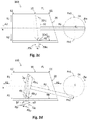
- the rotatable member can be a rotatable rod 60rr driven by a motor 60m, as shown in Fig. 5 .
- One end of the rotatable rod 60rr is coupled to the second rod end 60rde2 of the piston rod 60rd and the other end of the rotatable rod 60rr is arranged to be driven by the motor 60m at the circle center C.
- the rotatory shaft of the motor 60m can be directly coupled to the other end of the rotatable rod 60rr at the circle center C, and can also be coupled thereto through other means, such as a gear set, a gear-and-chain set, etc.
- the rotatable member can also be a gear set 60rg driven by a motor 60m, as shown in Figs. 6a-6h.
- Figs. 6a-6h show a preferred embodiment with individual steps when the piston 30 is driven to remove the fluid-tight sealing for allowing fluid to enter, and to close the fluid-tight sealing for pushing the fluid in the second axial direction A2.
- Figs. 6a-6i show that the fluid cylinder 100 may be a gas cylinder 200 used in a gas compressor 1000 with gas outlet valve Vout at the second tube end E2 for releasing gas out of the cylinder tube 10.
- the gas outside the gas cylinder 200 can enter into the cylinder tube 10 through gas inlet means by removing at least a part of the gas-tight sealing between the piston 30 and the inner wall 50 of the cylinder tube 10. Then, the gas is pushed and compressed by the piston 30 so as to flow out of the cylinder tube 10 through the gas outlet valve Vout then into for example a compressed gas storage container or a tire of a vehicle which uses compressed gas such as air.
- the closed orbit Oc may also be in other shapes realized by any proper mechanical rotating means which can produce non-circular closed rotating orbit.
- Fig. 7a and 7b show elliptical closed orbits.
- the elliptical closed orbit Oc in Fig. 7a is symmetric with respect to the tube axis a, and in this case it is required that the first angle ⁇ is larger than 0°, so that it is possible to fulfil the conditions defined by equations (1)-(6).
- the elliptical closed orbit Oc in Fig. 7a has a longer axis in the radial direction than the axis in the axial direction, which can shorten the moving distance of the piston 30 in the axial direction.
- the elliptical closed orbit is shifted in the first radial direction R1, which is similar to the situation shown in Fig. 4 .
- the first angle ⁇ may be reduced, or even may be equal to or smaller than 0°, as long as the conditions defined in equations (1)-(6) can be fulfilled.
Landscapes
- Engineering & Computer Science (AREA)
- General Engineering & Computer Science (AREA)
- Mechanical Engineering (AREA)
- Chemical & Material Sciences (AREA)
- Combustion & Propulsion (AREA)
- Compressor (AREA)
- Actuator (AREA)
Priority Applications (1)
| Application Number | Priority Date | Filing Date | Title |
|---|---|---|---|
| PL14839823T PL3039293T3 (pl) | 2013-08-30 | 2014-06-10 | Cylinder płynowy |
Applications Claiming Priority (3)
| Application Number | Priority Date | Filing Date | Title |
|---|---|---|---|
| CN201310385456.XA CN103410704B (zh) | 2013-08-30 | 2013-08-30 | 一种自进气式气缸及具有该自进气式气缸的空压机 |
| CN201320534101.8U CN203453007U (zh) | 2013-08-30 | 2013-08-30 | 一种自进气式气缸及具有该自进气式气缸的空压机 |
| PCT/CN2014/079606 WO2015027729A1 (en) | 2013-08-30 | 2014-06-10 | A fluid cylinder |
Publications (3)
| Publication Number | Publication Date |
|---|---|
| EP3039293A1 EP3039293A1 (en) | 2016-07-06 |
| EP3039293A4 EP3039293A4 (en) | 2016-08-10 |
| EP3039293B1 true EP3039293B1 (en) | 2018-09-19 |
Family
ID=52585507
Family Applications (1)
| Application Number | Title | Priority Date | Filing Date |
|---|---|---|---|
| EP14839823.3A Active EP3039293B1 (en) | 2013-08-30 | 2014-06-10 | A fluid cylinder |
Country Status (6)
| Country | Link |
|---|---|
| US (1) | US20160201660A1 (pl) |
| EP (1) | EP3039293B1 (pl) |
| JP (1) | JP2016537559A (pl) |
| KR (1) | KR101790855B1 (pl) |
| PL (1) | PL3039293T3 (pl) |
| WO (1) | WO2015027729A1 (pl) |
Families Citing this family (6)
| Publication number | Priority date | Publication date | Assignee | Title |
|---|---|---|---|---|
| TWI579460B (zh) * | 2014-10-08 | 2017-04-21 | Wen-San Jhou | 空氣壓縮機之結合構造改良 |
| JP6023255B1 (ja) | 2015-04-17 | 2016-11-09 | イリソ電子工業株式会社 | コネクタ |
| JP7554044B2 (ja) * | 2019-10-01 | 2024-09-19 | 株式会社日立産機システム | 圧縮機 |
| JP7449061B2 (ja) * | 2019-10-01 | 2024-03-13 | 株式会社日立産機システム | 圧縮機 |
| JP7709286B2 (ja) * | 2021-02-25 | 2025-07-16 | 株式会社日立産機システム | 往復動圧縮機 |
| CN117703868B (zh) * | 2024-01-12 | 2024-06-07 | 江苏亚力亚气动液压成套设备有限公司 | 一种便于动力输出角度调整的组合液压缸 |
Family Cites Families (23)
| Publication number | Priority date | Publication date | Assignee | Title |
|---|---|---|---|---|
| US2023466A (en) * | 1933-02-18 | 1935-12-10 | Blake F Hopkins | Pump |
| US2284645A (en) * | 1941-01-27 | 1942-06-02 | Duffy Charles Hugh | Air pump or compressor |
| US3078033A (en) * | 1959-08-03 | 1963-02-19 | Ovrutsky Irving | Pumping means |
| US3082935A (en) * | 1961-03-01 | 1963-03-26 | Henry M Arak | Aquarium pump |
| US3523001A (en) * | 1968-07-30 | 1970-08-04 | Aai Corp | Aerosol sampler arrangement and pump therefor |
| US4765292A (en) * | 1985-08-19 | 1988-08-23 | Morgado Ralph G | Self-sealing piston apparatus |
| CN2032641U (zh) * | 1988-05-24 | 1989-02-15 | 耿洪生 | 液压缓冲式关门器 |
| CN2216135Y (zh) * | 1994-09-12 | 1995-12-27 | 温州市建庆实业公司 | 自动闭门器 |
| FR2752310B1 (fr) * | 1996-08-09 | 1998-10-09 | Wabco France | Procede et dispositif de regulation de la pression d'un circuit de fluide |
| DE19918128A1 (de) * | 1999-04-21 | 2000-10-26 | Dieter Moellmann | Absperrklappe für Rohrleitungen und Verfahren zur Herstellung derselben |
| JP2001271744A (ja) * | 2000-03-24 | 2001-10-05 | Denso Corp | エアコンプレッサ |
| CN2489054Y (zh) * | 2001-06-21 | 2002-05-01 | 吴广 | 气压式闭门器 |
| DE60309280T2 (de) * | 2003-01-07 | 2007-02-01 | Jhou, Wen-San, An-Din | Integriertes Ringventil für einen Kompressorkolben |
| EP1637746A2 (de) * | 2004-09-17 | 2006-03-22 | LuK Lamellen und Kupplungsbau Beteiligungs KG | Hydraulikzylinder, insbesondere Geberzylinder eines hydraulischen Kupplungsausrücksystems |
| DE102008031848B4 (de) * | 2008-07-05 | 2018-09-13 | Wabco Gmbh | Kolbenkompressor |
| CN101776061A (zh) * | 2010-03-05 | 2010-07-14 | 浙江鸿友压缩机制造有限公司 | 活塞阀控进气无油润滑空气压缩机 |
| EP2652338A4 (en) * | 2010-12-14 | 2014-05-07 | Volvo Lastvagnar Ab | HYDRAULIC DEVICE, VEHICLE COMPRISING SUCH A HYDRAULIC DEVICE AND USE OF SUCH A HYDRAULIC DEVICE FOR TILTING A CABIN ARRANGED ON A CHASSIS |
| TWI531721B (zh) * | 2011-01-25 | 2016-05-01 | 周文三 | 空氣壓縮機 |
| JP5374524B2 (ja) * | 2011-01-26 | 2013-12-25 | 住友ゴム工業株式会社 | コンプレッサ装置 |
| CN103410704B (zh) * | 2013-08-30 | 2016-12-28 | 东莞瑞柯电子科技股份有限公司 | 一种自进气式气缸及具有该自进气式气缸的空压机 |
| CN203453007U (zh) * | 2013-08-30 | 2014-02-26 | 东莞瑞柯电子科技股份有限公司 | 一种自进气式气缸及具有该自进气式气缸的空压机 |
| JP6595457B2 (ja) * | 2013-09-24 | 2019-10-23 | イリノイ トゥール ワークス インコーポレイティド | 圧縮機 |
| TWI591257B (zh) * | 2014-05-15 | 2017-07-11 | 周文三 | 空氣壓縮機之旋轉機構 |
-
2014
- 2014-06-10 WO PCT/CN2014/079606 patent/WO2015027729A1/en not_active Ceased
- 2014-06-10 EP EP14839823.3A patent/EP3039293B1/en active Active
- 2014-06-10 US US14/914,107 patent/US20160201660A1/en not_active Abandoned
- 2014-06-10 JP JP2016537096A patent/JP2016537559A/ja active Pending
- 2014-06-10 KR KR1020157014012A patent/KR101790855B1/ko active Active
- 2014-06-10 PL PL14839823T patent/PL3039293T3/pl unknown
Non-Patent Citations (1)
| Title |
|---|
| None * |
Also Published As
| Publication number | Publication date |
|---|---|
| KR20150079872A (ko) | 2015-07-08 |
| WO2015027729A1 (en) | 2015-03-05 |
| PL3039293T3 (pl) | 2019-02-28 |
| EP3039293A1 (en) | 2016-07-06 |
| EP3039293A4 (en) | 2016-08-10 |
| KR101790855B1 (ko) | 2017-10-26 |
| US20160201660A1 (en) | 2016-07-14 |
| JP2016537559A (ja) | 2016-12-01 |
Similar Documents
| Publication | Publication Date | Title |
|---|---|---|
| EP3039293B1 (en) | A fluid cylinder | |
| US10364813B2 (en) | Liquid transport device with decreasing pitches | |
| CN108894978A (zh) | 一种高压泵及高压泵送方法 | |
| US20190234389A1 (en) | Fluid Cylinder | |
| CN106062365B (zh) | 隔膜的固定构造、具备其的隔膜泵以及阀装置 | |
| US20130011292A1 (en) | Dual rotor pump | |
| US9982672B2 (en) | Fuel pump | |
| RU2109192C1 (ru) | Запорное устройство | |
| EP2924324B1 (en) | Rotation shaft seal | |
| KR20240119133A (ko) | 일축 편심 나사 펌프 | |
| CN106321880B (zh) | 一种用于密封阀密封的密封结构 | |
| JP2015194246A (ja) | 軸密封構造 | |
| TW201537069A (zh) | 節流閥 | |
| EP2357389A1 (en) | Press fitting apparatus having a sealing ring | |
| CN109424779A (zh) | 电动液压阀和用于制造电动液压阀的方法 | |
| US20190049018A1 (en) | Seal ring | |
| EP3187763A1 (en) | Coupling for connecting and sealing fluid handling components | |
| CN209308940U (zh) | 一种高压泵 | |
| JP7138382B1 (ja) | 一軸偏心ねじポンプ | |
| CN106170649A (zh) | P04tu压环 | |
| KR101549673B1 (ko) | 핀치 밸브 | |
| CN108194652A (zh) | 一种新型小流量气体按钮阀 | |
| CN216742845U (zh) | 电磁阀及空调设备 | |
| EP3000633A1 (en) | Vehicle air conditioning system seal and assembly having a vehicle air conditioning system seal | |
| CN209540272U (zh) | 一种汽车温控系统的管路接头及汽车 |
Legal Events
| Date | Code | Title | Description |
|---|---|---|---|
| PUAI | Public reference made under article 153(3) epc to a published international application that has entered the european phase |
Free format text: ORIGINAL CODE: 0009012 |
|
| 17P | Request for examination filed |
Effective date: 20150608 |
|
| AK | Designated contracting states |
Kind code of ref document: A1 Designated state(s): AL AT BE BG CH CY CZ DE DK EE ES FI FR GB GR HR HU IE IS IT LI LT LU LV MC MK MT NL NO PL PT RO RS SE SI SK SM TR |
|
| AX | Request for extension of the european patent |
Extension state: BA ME |
|
| REG | Reference to a national code |
Ref country code: DE Ref legal event code: R079 Ref document number: 602014032721 Country of ref document: DE Free format text: PREVIOUS MAIN CLASS: F04B0039000000 Ipc: F04B0039120000 |
|
| A4 | Supplementary search report drawn up and despatched |
Effective date: 20160713 |
|
| RIC1 | Information provided on ipc code assigned before grant |
Ipc: F04B 53/12 20060101ALI20160707BHEP Ipc: F16J 10/02 20060101ALI20160707BHEP Ipc: F04B 39/12 20060101AFI20160707BHEP Ipc: F04B 27/08 20060101ALI20160707BHEP Ipc: F16J 1/00 20060101ALI20160707BHEP Ipc: F04B 39/00 20060101ALI20160707BHEP |
|
| DAX | Request for extension of the european patent (deleted) | ||
| STAA | Information on the status of an ep patent application or granted ep patent |
Free format text: STATUS: EXAMINATION IS IN PROGRESS |
|
| 17Q | First examination report despatched |
Effective date: 20170522 |
|
| GRAP | Despatch of communication of intention to grant a patent |
Free format text: ORIGINAL CODE: EPIDOSNIGR1 |
|
| STAA | Information on the status of an ep patent application or granted ep patent |
Free format text: STATUS: GRANT OF PATENT IS INTENDED |
|
| INTG | Intention to grant announced |
Effective date: 20180508 |
|
| GRAS | Grant fee paid |
Free format text: ORIGINAL CODE: EPIDOSNIGR3 |
|
| GRAA | (expected) grant |
Free format text: ORIGINAL CODE: 0009210 |
|
| STAA | Information on the status of an ep patent application or granted ep patent |
Free format text: STATUS: THE PATENT HAS BEEN GRANTED |
|
| AK | Designated contracting states |
Kind code of ref document: B1 Designated state(s): AL AT BE BG CH CY CZ DE DK EE ES FI FR GB GR HR HU IE IS IT LI LT LU LV MC MK MT NL NO PL PT RO RS SE SI SK SM TR |
|
| REG | Reference to a national code |
Ref country code: GB Ref legal event code: FG4D |
|
| REG | Reference to a national code |
Ref country code: CH Ref legal event code: EP |
|
| REG | Reference to a national code |
Ref country code: AT Ref legal event code: REF Ref document number: 1043568 Country of ref document: AT Kind code of ref document: T Effective date: 20181015 |
|
| REG | Reference to a national code |
Ref country code: IE Ref legal event code: FG4D |
|
| REG | Reference to a national code |
Ref country code: DE Ref legal event code: R096 Ref document number: 602014032721 Country of ref document: DE |
|
| REG | Reference to a national code |
Ref country code: NL Ref legal event code: MP Effective date: 20180919 |
|
| PG25 | Lapsed in a contracting state [announced via postgrant information from national office to epo] |
Ref country code: FI Free format text: LAPSE BECAUSE OF FAILURE TO SUBMIT A TRANSLATION OF THE DESCRIPTION OR TO PAY THE FEE WITHIN THE PRESCRIBED TIME-LIMIT Effective date: 20180919 Ref country code: SE Free format text: LAPSE BECAUSE OF FAILURE TO SUBMIT A TRANSLATION OF THE DESCRIPTION OR TO PAY THE FEE WITHIN THE PRESCRIBED TIME-LIMIT Effective date: 20180919 Ref country code: RS Free format text: LAPSE BECAUSE OF FAILURE TO SUBMIT A TRANSLATION OF THE DESCRIPTION OR TO PAY THE FEE WITHIN THE PRESCRIBED TIME-LIMIT Effective date: 20180919 Ref country code: NO Free format text: LAPSE BECAUSE OF FAILURE TO SUBMIT A TRANSLATION OF THE DESCRIPTION OR TO PAY THE FEE WITHIN THE PRESCRIBED TIME-LIMIT Effective date: 20181219 Ref country code: GR Free format text: LAPSE BECAUSE OF FAILURE TO SUBMIT A TRANSLATION OF THE DESCRIPTION OR TO PAY THE FEE WITHIN THE PRESCRIBED TIME-LIMIT Effective date: 20181220 Ref country code: BG Free format text: LAPSE BECAUSE OF FAILURE TO SUBMIT A TRANSLATION OF THE DESCRIPTION OR TO PAY THE FEE WITHIN THE PRESCRIBED TIME-LIMIT Effective date: 20181219 Ref country code: LT Free format text: LAPSE BECAUSE OF FAILURE TO SUBMIT A TRANSLATION OF THE DESCRIPTION OR TO PAY THE FEE WITHIN THE PRESCRIBED TIME-LIMIT Effective date: 20180919 |
|
| REG | Reference to a national code |
Ref country code: LT Ref legal event code: MG4D |
|
| PG25 | Lapsed in a contracting state [announced via postgrant information from national office to epo] |
Ref country code: AL Free format text: LAPSE BECAUSE OF FAILURE TO SUBMIT A TRANSLATION OF THE DESCRIPTION OR TO PAY THE FEE WITHIN THE PRESCRIBED TIME-LIMIT Effective date: 20180919 Ref country code: LV Free format text: LAPSE BECAUSE OF FAILURE TO SUBMIT A TRANSLATION OF THE DESCRIPTION OR TO PAY THE FEE WITHIN THE PRESCRIBED TIME-LIMIT Effective date: 20180919 Ref country code: HR Free format text: LAPSE BECAUSE OF FAILURE TO SUBMIT A TRANSLATION OF THE DESCRIPTION OR TO PAY THE FEE WITHIN THE PRESCRIBED TIME-LIMIT Effective date: 20180919 |
|
| REG | Reference to a national code |
Ref country code: AT Ref legal event code: MK05 Ref document number: 1043568 Country of ref document: AT Kind code of ref document: T Effective date: 20180919 |
|
| PG25 | Lapsed in a contracting state [announced via postgrant information from national office to epo] |
Ref country code: IS Free format text: LAPSE BECAUSE OF FAILURE TO SUBMIT A TRANSLATION OF THE DESCRIPTION OR TO PAY THE FEE WITHIN THE PRESCRIBED TIME-LIMIT Effective date: 20190119 Ref country code: NL Free format text: LAPSE BECAUSE OF FAILURE TO SUBMIT A TRANSLATION OF THE DESCRIPTION OR TO PAY THE FEE WITHIN THE PRESCRIBED TIME-LIMIT Effective date: 20180919 Ref country code: AT Free format text: LAPSE BECAUSE OF FAILURE TO SUBMIT A TRANSLATION OF THE DESCRIPTION OR TO PAY THE FEE WITHIN THE PRESCRIBED TIME-LIMIT Effective date: 20180919 Ref country code: ES Free format text: LAPSE BECAUSE OF FAILURE TO SUBMIT A TRANSLATION OF THE DESCRIPTION OR TO PAY THE FEE WITHIN THE PRESCRIBED TIME-LIMIT Effective date: 20180919 Ref country code: CZ Free format text: LAPSE BECAUSE OF FAILURE TO SUBMIT A TRANSLATION OF THE DESCRIPTION OR TO PAY THE FEE WITHIN THE PRESCRIBED TIME-LIMIT Effective date: 20180919 Ref country code: RO Free format text: LAPSE BECAUSE OF FAILURE TO SUBMIT A TRANSLATION OF THE DESCRIPTION OR TO PAY THE FEE WITHIN THE PRESCRIBED TIME-LIMIT Effective date: 20180919 Ref country code: EE Free format text: LAPSE BECAUSE OF FAILURE TO SUBMIT A TRANSLATION OF THE DESCRIPTION OR TO PAY THE FEE WITHIN THE PRESCRIBED TIME-LIMIT Effective date: 20180919 |
|
| PG25 | Lapsed in a contracting state [announced via postgrant information from national office to epo] |
Ref country code: SM Free format text: LAPSE BECAUSE OF FAILURE TO SUBMIT A TRANSLATION OF THE DESCRIPTION OR TO PAY THE FEE WITHIN THE PRESCRIBED TIME-LIMIT Effective date: 20180919 Ref country code: PT Free format text: LAPSE BECAUSE OF FAILURE TO SUBMIT A TRANSLATION OF THE DESCRIPTION OR TO PAY THE FEE WITHIN THE PRESCRIBED TIME-LIMIT Effective date: 20190119 Ref country code: SK Free format text: LAPSE BECAUSE OF FAILURE TO SUBMIT A TRANSLATION OF THE DESCRIPTION OR TO PAY THE FEE WITHIN THE PRESCRIBED TIME-LIMIT Effective date: 20180919 |
|
| REG | Reference to a national code |
Ref country code: DE Ref legal event code: R097 Ref document number: 602014032721 Country of ref document: DE |
|
| PLBE | No opposition filed within time limit |
Free format text: ORIGINAL CODE: 0009261 |
|
| STAA | Information on the status of an ep patent application or granted ep patent |
Free format text: STATUS: NO OPPOSITION FILED WITHIN TIME LIMIT |
|
| PG25 | Lapsed in a contracting state [announced via postgrant information from national office to epo] |
Ref country code: DK Free format text: LAPSE BECAUSE OF FAILURE TO SUBMIT A TRANSLATION OF THE DESCRIPTION OR TO PAY THE FEE WITHIN THE PRESCRIBED TIME-LIMIT Effective date: 20180919 |
|
| 26N | No opposition filed |
Effective date: 20190620 |
|
| PG25 | Lapsed in a contracting state [announced via postgrant information from national office to epo] |
Ref country code: SI Free format text: LAPSE BECAUSE OF FAILURE TO SUBMIT A TRANSLATION OF THE DESCRIPTION OR TO PAY THE FEE WITHIN THE PRESCRIBED TIME-LIMIT Effective date: 20180919 |
|
| PG25 | Lapsed in a contracting state [announced via postgrant information from national office to epo] |
Ref country code: MC Free format text: LAPSE BECAUSE OF FAILURE TO SUBMIT A TRANSLATION OF THE DESCRIPTION OR TO PAY THE FEE WITHIN THE PRESCRIBED TIME-LIMIT Effective date: 20180919 |
|
| REG | Reference to a national code |
Ref country code: CH Ref legal event code: PL |
|
| REG | Reference to a national code |
Ref country code: BE Ref legal event code: MM Effective date: 20190630 |
|
| PG25 | Lapsed in a contracting state [announced via postgrant information from national office to epo] |
Ref country code: IE Free format text: LAPSE BECAUSE OF NON-PAYMENT OF DUE FEES Effective date: 20190610 |
|
| PG25 | Lapsed in a contracting state [announced via postgrant information from national office to epo] |
Ref country code: LU Free format text: LAPSE BECAUSE OF NON-PAYMENT OF DUE FEES Effective date: 20190610 Ref country code: LI Free format text: LAPSE BECAUSE OF NON-PAYMENT OF DUE FEES Effective date: 20190630 Ref country code: CH Free format text: LAPSE BECAUSE OF NON-PAYMENT OF DUE FEES Effective date: 20190630 Ref country code: BE Free format text: LAPSE BECAUSE OF NON-PAYMENT OF DUE FEES Effective date: 20190630 |
|
| PG25 | Lapsed in a contracting state [announced via postgrant information from national office to epo] |
Ref country code: CY Free format text: LAPSE BECAUSE OF FAILURE TO SUBMIT A TRANSLATION OF THE DESCRIPTION OR TO PAY THE FEE WITHIN THE PRESCRIBED TIME-LIMIT Effective date: 20180919 |
|
| PG25 | Lapsed in a contracting state [announced via postgrant information from national office to epo] |
Ref country code: MT Free format text: LAPSE BECAUSE OF FAILURE TO SUBMIT A TRANSLATION OF THE DESCRIPTION OR TO PAY THE FEE WITHIN THE PRESCRIBED TIME-LIMIT Effective date: 20180919 Ref country code: HU Free format text: LAPSE BECAUSE OF FAILURE TO SUBMIT A TRANSLATION OF THE DESCRIPTION OR TO PAY THE FEE WITHIN THE PRESCRIBED TIME-LIMIT; INVALID AB INITIO Effective date: 20140610 |
|
| PG25 | Lapsed in a contracting state [announced via postgrant information from national office to epo] |
Ref country code: MK Free format text: LAPSE BECAUSE OF FAILURE TO SUBMIT A TRANSLATION OF THE DESCRIPTION OR TO PAY THE FEE WITHIN THE PRESCRIBED TIME-LIMIT Effective date: 20180919 |
|
| P01 | Opt-out of the competence of the unified patent court (upc) registered |
Effective date: 20230519 |
|
| PGFP | Annual fee paid to national office [announced via postgrant information from national office to epo] |
Ref country code: PL Payment date: 20250526 Year of fee payment: 12 Ref country code: DE Payment date: 20250617 Year of fee payment: 12 |
|
| PGFP | Annual fee paid to national office [announced via postgrant information from national office to epo] |
Ref country code: GB Payment date: 20250625 Year of fee payment: 12 |
|
| PGFP | Annual fee paid to national office [announced via postgrant information from national office to epo] |
Ref country code: FR Payment date: 20250630 Year of fee payment: 12 |
|
| PGFP | Annual fee paid to national office [announced via postgrant information from national office to epo] |
Ref country code: TR Payment date: 20250529 Year of fee payment: 12 |
|
| PGFP | Annual fee paid to national office [announced via postgrant information from national office to epo] |
Ref country code: IT Payment date: 20250609 Year of fee payment: 12 |