EP3037899A1 - Piece d'horlogerie comportant un mobile de position angulaire determinable - Google Patents
Piece d'horlogerie comportant un mobile de position angulaire determinable Download PDFInfo
- Publication number
- EP3037899A1 EP3037899A1 EP15202349.5A EP15202349A EP3037899A1 EP 3037899 A1 EP3037899 A1 EP 3037899A1 EP 15202349 A EP15202349 A EP 15202349A EP 3037899 A1 EP3037899 A1 EP 3037899A1
- Authority
- EP
- European Patent Office
- Prior art keywords
- electrode
- mobile
- electrodes
- opening
- rotation
- Prior art date
- Legal status (The legal status is an assumption and is not a legal conclusion. Google has not performed a legal analysis and makes no representation as to the accuracy of the status listed.)
- Granted
Links
Images

Classifications
-
- G—PHYSICS
- G04—HOROLOGY
- G04C—ELECTROMECHANICAL CLOCKS OR WATCHES
- G04C3/00—Electromechanical clocks or watches independent of other time-pieces and in which the movement is maintained by electric means
- G04C3/14—Electromechanical clocks or watches independent of other time-pieces and in which the movement is maintained by electric means incorporating a stepping motor
-
- G—PHYSICS
- G01—MEASURING; TESTING
- G01B—MEASURING LENGTH, THICKNESS OR SIMILAR LINEAR DIMENSIONS; MEASURING ANGLES; MEASURING AREAS; MEASURING IRREGULARITIES OF SURFACES OR CONTOURS
- G01B7/00—Measuring arrangements characterised by the use of electric or magnetic techniques
- G01B7/30—Measuring arrangements characterised by the use of electric or magnetic techniques for measuring angles or tapers; for testing the alignment of axes
-
- G—PHYSICS
- G01—MEASURING; TESTING
- G01D—MEASURING NOT SPECIALLY ADAPTED FOR A SPECIFIC VARIABLE; ARRANGEMENTS FOR MEASURING TWO OR MORE VARIABLES NOT COVERED IN A SINGLE OTHER SUBCLASS; TARIFF METERING APPARATUS; MEASURING OR TESTING NOT OTHERWISE PROVIDED FOR
- G01D5/00—Mechanical means for transferring the output of a sensing member; Means for converting the output of a sensing member to another variable where the form or nature of the sensing member does not constrain the means for converting; Transducers not specially adapted for a specific variable
- G01D5/12—Mechanical means for transferring the output of a sensing member; Means for converting the output of a sensing member to another variable where the form or nature of the sensing member does not constrain the means for converting; Transducers not specially adapted for a specific variable using electric or magnetic means
- G01D5/14—Mechanical means for transferring the output of a sensing member; Means for converting the output of a sensing member to another variable where the form or nature of the sensing member does not constrain the means for converting; Transducers not specially adapted for a specific variable using electric or magnetic means influencing the magnitude of a current or voltage
- G01D5/24—Mechanical means for transferring the output of a sensing member; Means for converting the output of a sensing member to another variable where the form or nature of the sensing member does not constrain the means for converting; Transducers not specially adapted for a specific variable using electric or magnetic means influencing the magnitude of a current or voltage by varying capacitance
- G01D5/241—Mechanical means for transferring the output of a sensing member; Means for converting the output of a sensing member to another variable where the form or nature of the sensing member does not constrain the means for converting; Transducers not specially adapted for a specific variable using electric or magnetic means influencing the magnitude of a current or voltage by varying capacitance by relative movement of capacitor electrodes
-
- G—PHYSICS
- G01—MEASURING; TESTING
- G01D—MEASURING NOT SPECIALLY ADAPTED FOR A SPECIFIC VARIABLE; ARRANGEMENTS FOR MEASURING TWO OR MORE VARIABLES NOT COVERED IN A SINGLE OTHER SUBCLASS; TARIFF METERING APPARATUS; MEASURING OR TESTING NOT OTHERWISE PROVIDED FOR
- G01D5/00—Mechanical means for transferring the output of a sensing member; Means for converting the output of a sensing member to another variable where the form or nature of the sensing member does not constrain the means for converting; Transducers not specially adapted for a specific variable
- G01D5/12—Mechanical means for transferring the output of a sensing member; Means for converting the output of a sensing member to another variable where the form or nature of the sensing member does not constrain the means for converting; Transducers not specially adapted for a specific variable using electric or magnetic means
- G01D5/14—Mechanical means for transferring the output of a sensing member; Means for converting the output of a sensing member to another variable where the form or nature of the sensing member does not constrain the means for converting; Transducers not specially adapted for a specific variable using electric or magnetic means influencing the magnitude of a current or voltage
- G01D5/24—Mechanical means for transferring the output of a sensing member; Means for converting the output of a sensing member to another variable where the form or nature of the sensing member does not constrain the means for converting; Transducers not specially adapted for a specific variable using electric or magnetic means influencing the magnitude of a current or voltage by varying capacitance
- G01D5/241—Mechanical means for transferring the output of a sensing member; Means for converting the output of a sensing member to another variable where the form or nature of the sensing member does not constrain the means for converting; Transducers not specially adapted for a specific variable using electric or magnetic means influencing the magnitude of a current or voltage by varying capacitance by relative movement of capacitor electrodes
- G01D5/2412—Mechanical means for transferring the output of a sensing member; Means for converting the output of a sensing member to another variable where the form or nature of the sensing member does not constrain the means for converting; Transducers not specially adapted for a specific variable using electric or magnetic means influencing the magnitude of a current or voltage by varying capacitance by relative movement of capacitor electrodes by varying overlap
-
- G—PHYSICS
- G04—HOROLOGY
- G04C—ELECTROMECHANICAL CLOCKS OR WATCHES
- G04C3/00—Electromechanical clocks or watches independent of other time-pieces and in which the movement is maintained by electric means
- G04C3/001—Electromechanical switches for setting or display
- G04C3/002—Position, e.g. inclination dependent switches
-
- G—PHYSICS
- G04—HOROLOGY
- G04C—ELECTROMECHANICAL CLOCKS OR WATCHES
- G04C3/00—Electromechanical clocks or watches independent of other time-pieces and in which the movement is maintained by electric means
- G04C3/14—Electromechanical clocks or watches independent of other time-pieces and in which the movement is maintained by electric means incorporating a stepping motor
- G04C3/146—Electromechanical clocks or watches independent of other time-pieces and in which the movement is maintained by electric means incorporating a stepping motor incorporating two or more stepping motors or rotors
-
- G—PHYSICS
- G04—HOROLOGY
- G04D—APPARATUS OR TOOLS SPECIALLY DESIGNED FOR MAKING OR MAINTAINING CLOCKS OR WATCHES
- G04D7/00—Measuring, counting, calibrating, testing or regulating apparatus
- G04D7/12—Timing devices for clocks or watches for comparing the rate of the oscillating member with a standard
- G04D7/1207—Timing devices for clocks or watches for comparing the rate of the oscillating member with a standard only for measuring
-
- G—PHYSICS
- G01—MEASURING; TESTING
- G01R—MEASURING ELECTRIC VARIABLES; MEASURING MAGNETIC VARIABLES
- G01R27/00—Arrangements for measuring resistance, reactance, impedance, or electric characteristics derived therefrom
- G01R27/02—Measuring real or complex resistance, reactance, impedance, or other two-pole characteristics derived therefrom, e.g. time constant
- G01R27/26—Measuring inductance or capacitance; Measuring quality factor, e.g. by using the resonance method; Measuring loss factor; Measuring dielectric constants ; Measuring impedance or related variables
Definitions
- the invention relates to the technical field of timepieces comprising a watch movement provided with an analog display and at least one movable integral in rotation with a rotary indicator of this analog display.
- the document EP 0 952 426 proposes to use an inductive sensor or a capacitive sensor, specifying however that a capacitive sensor is more sensitive to the environment and to the disturbances caused by manufacturing and assembly tolerances than an inductive sensor.
- a capacitive sensor is particularly influenced by the high pitch, in the direction of the axis of rotation of the mobile, between the mobile and the sensor. The bigger this step, the higher the peak: the accuracy of the detection of the reference angular position is therefore directly impacted by the height frost.
- the object of the present invention is to overcome the disadvantage mentioned above by proposing a solution for determining the angular position of a moving body by a capacitive sensor, the accuracy of which is not affected by the variations in pitch frictions between the mobile and the sensor.
- the first electrode and the common electrode form a first electrical capacitor of capacitance called C1, while the second electrode and the common electrode form a second electrical capacitor of capacitance called C2.
- a stepping motor for subjecting the mobile to a complete rotation step by step, and a measuring circuit for generating a measurement signal representing VS 1 - VS 2 VS 1 + VS 2 according to the number of steps, we obtain a curve presenting a maximum and a minimum. The maximum is observed when the opening is in the first unbalanced position; the minimum is observed when the opening is in the second position of imbalance; the curve is of zero value when the opening is in the equilibrium position.
- the maximum and the minimum are characteristic of mobile-specific angular positons, when the maximum and the minimum have been identified on the graph representing the measurement signal, it is possible to deduce the angular position of the mobile corresponding to another point of the mobile. graphic. It is particularly possible to deduce the initial angular position of the mobile, that is to say, its position before it starts the rotation, which is the desired position.
- plane electrode a conductive part extending significantly in at least two directions in a plane, in opposition to the stick electrodes.
- the mobile plate may comprise more than one opening
- the detection device may comprise more than one set of electrodes of the aforementioned type.
- each opening is arranged to be facing the first and the second electrode of a game in a specific position of the mobile.
- the timepiece may include one or more of the features below, in any technically possible combination.
- the electrodes all have a substantially identical area. This configuration is at the origin of a significant imbalance between the capacitance C1 and the capacitance C2, and consequently of an amplitude in important norm of the maximum and the minimum of the curve. Moreover, it is noted that in certain configurations of the electrodes, the curve has a setback between the peak corresponding to the maximum and the trough corresponding to the minimum. A recess is understood to mean a section with a lower slope than either side of the section. The configuration just mentioned makes it possible to minimize the length of this setback.
- the opening is at least partially above or below the common electrode in the first unbalance position, the equilibrium position and the second unbalance position. This configuration makes it possible to obtain a peak and a hollow particularly marked.
- the three electrodes are wholly above or below the opening in the second position.
- the opening of the mobile is then possibly smaller than the set of electrodes. This configuration eliminates any discrepancy between the peak and the trough of the curve.
- the common electrode comprises two planar half-electrodes electrically connected to each other, the half-electrodes being disposed on either side of the assembly constituted by the first and the second electrode.
- the common electrode comprises two planar half-electrodes electrically connected to each other, the half-electrodes being disposed between the first and the second electrode.
- the first electrode and the second electrode are side by side, and the common electrode extends substantially in the form of an annular portion along the first and the second electrode.
- This configuration makes it possible to use a first and a second electrode of large surfaces, for example a first and a second electrode whose total surface is substantially that of the opening. Important surfaces of the first and the second electrode are at the origin of a large amplitude in norm of the maximum and the minimum on the curve.
- the invention relates to a timepiece comprising a watch movement.
- the watch movement comprises a mobile disc-shaped MB, which further comprises a shaft defining a geometric axis of rotation.
- the watch movement is associated with an analog display comprising a rotary indicator fixedly mounted on the shaft, not shown.
- the indicator can be used to indicate the hour, minute, second, or other information provided for an analog display.
- the mobile MB comprises an electrically conductive plate PT, extending substantially orthogonal to the axis of rotation of the mobile MB.
- Said plate PT is pierced with a through opening OV shaped annular portion, placed in an intermediate region between its periphery and a central hole provided for the passage of the shaft.
- the through opening OV for example extends over 120 degrees.
- a plate PA Opposite the mobile MB, above or below the mobile MB, is positioned a plate PA, for example in the form of a half-disk.
- the plate PA extends substantially parallel to the plate PL of the mobile MB and orthogonal to the axis of rotation of the mobile MB.
- the plate PA is a printed circuit board (printed circuit board in English terminology, PCB) on which three planar electrodes are printed.
- PCB printed circuit board in English terminology, PCB
- the plate PA comprises a set of electrodes.
- the set of electrodes comprises three planar electrodes, called first electrode E1, second electrode E2, and common electrode Em.
- the three electrodes E1, E2, Em have the shape of annular portions.
- the common electrode Em is arranged along portions of the first electrode E1 and the second electrode E2, so as to form, with the first electrode E1, a first capacitive electric capacitor C1, and with the second electrode E2 a second capacitor. electrical capacitance called C2. Due to the presence of the OV opening in the plateau PT, the value of the capacitors C1, C2 depends on the angular position of the mobile MB relative to the electrodes E1, E2, Em.
- the capacitor C1, respectively C2 is maximum when the opening OV is above the first electrode E1 and the common electrode Em, respectively above the second electrode E2 and the common electrode Em, since the transfer of electrical charges from one electrode to the other is no longer facilitated by the presence of the electrically conductive material of the plate PT .
- FIG. figure 1 A first configuration of these electrodes E1, E2, Em on the plate PA is shown in FIG. figure 1 .
- the three electrodes E1, E2, Em are of substantially identical surfaces, and the common electrode Em is placed between the first electrode E1 and the second electrode E2.
- the total area of the electrodes E1, E2, Em is substantially of the order of the surface of the opening OV.
- stepper motor for example a bipolar engine of the "Lavet motor” type.
- the transmission of the motor to the mobile is preferably constituted by a gear train.
- An electronic measuring circuit comprising for example a microcontroller, is arranged to measure the value of VS 1 - VS 2 VS 1 + VS 2 according to the number of steps imposed on the mobile MB, and generate a measurement curve CB.
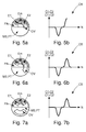
- FIGS. 2a, 3a, 4a , 5a, 6a and 7a show successive angular positions of the mobile MB relative to the plate PT during a complete rotation of said mobile MB from the position of the figure 1 .
- the first electrode E1 only is vis-à-vis the OV opening of the mobile MB.
- the first electrode E1 and the common electrode Em are opposite the opening OV.
- the three electrodes E1, E2, Em are all three vis-à-vis the opening.
- the common electrode Em and the second electrode E2 are vis-à-vis the opening.
- the Figures 2b, 3b, 4b , 5b, 6b and 7b illustrate the measurement curve CB representing VS 1 - VS 2 VS 1 + VS 2 according to a number of steps N imposed on the mobile phone MB, at times corresponding to the positions occupied by the mobile phone MB FIGS. 2a, 3a, 4a , 5a, 6a and 7a .
- the measurement curve CB is of zero value from the initial position of the mobile unit MB to the position of the figure 2a . Then, as shown in figure 3b , the value of VS 1 - VS 2 VS 1 + VS 2 decreases between the position of the figure 2a and the position of the figure 3a .
- the curve CB reaches in particular a minimum value when the electrode E1 and the common electrode Em are both, and only two, vis-à-vis the opening OV.
- the values taken by the curve CB increase until returning to a null value between the position of the figure 3a and the position of the figure 4a .
- the value VS 1 - VS 2 VS 1 + VS 2 decreases between the position of the figure 4a and the position of the figure 5a .
- the curve CB reaches in particular a maximum value when the electrode E2 and the common electrode Em are both, and only two, vis-à-vis the opening OV.
- the curve CB By exploiting the curve CB, two characteristic positions of the mobile MB are then calculated. In the first, which corresponds to the position of the figure 3a the CB curve has a minimum; in the second, which corresponds to the position of the figure 5a , the curve CB has a maximum. Since the number of steps to reach the position corresponding to the minimum and the position corresponding to the maximum can be determined from the curve CB, it is easy to deduce the initial position of the mobile MB.
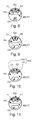
- the electrodes E1, E2, Em are similar to those of the figure 1 , but the opening OV extends over 80 degrees only (naturally, this angular opening is not limiting). There is therefore no angular position of the mobile MB in which the three electrodes E1, E2, Em are fully vis-à-vis the OV opening.
- This configuration makes it possible to avoid the offset, observed on the figure 7b , between the peak corresponding to the maximum and the hollow corresponding to the minimum.
- the three electrodes E1, E2, Em are not of identical surfaces: the first electrode E1 and the second electrode E2 are of the same surfaces but the common electrode Em is of upper surface.
- the first electrode E1 and the second electrode E2 extend over 10 degrees, while the common electrode Em extends over 18 degrees (naturally, these angular characteristics are not limiting).
- the opening OV however extends over 120 degrees: the surface of the opening OV is therefore considerably larger than the sum of the surfaces of the electrodes E1, E2, Em.
- the first electrode E1 and the second electrode E2 are rib-side, and the common electrode Em consists of two electrically-connected half-electrodes (the connection is not shown).
- the half-electrodes are placed on either side of the assembly constituted by the first electrode E1 and the second electrode E2. It will be noted that alternatively, the two half-electrodes could be placed between the first electrode E1 and the second electrode E2.
- the first electrode E1 and the second electrode E2 are side by side, and the common electrode Em is arranged along the outer portion of these electrodes E1, E2.
- the total area of the first electrode E1 and the second electrode E2 is substantially equal to the area of the opening OV. There is therefore no position in which the common electrode Em is vis-à-vis the OV opening.
- This configuration makes it possible to increase the surfaces of the first electrode E1 and the second electrode E2, and thus the amplitude of the peak and the trough of the measurement curve CB.
- this configuration makes it possible to avoid the offset observed on the figure 7b , between the peak corresponding to the maximum and the hollow corresponding to the minimum.
- the present invention is not limited to the examples illustrated but is susceptible of various variations and modifications that will occur to those skilled in the art.
- the MB mobile could be pierced with K openings OV, K ⁇ 2, and the plate PA could comprise K sets of 3 electrodes such as those presented above. This would make it possible to obtain larger amplitudes (in standard) of the peak and the trough of the measurement curve.
Landscapes
- Physics & Mathematics (AREA)
- General Physics & Mathematics (AREA)
- Engineering & Computer Science (AREA)
- Power Engineering (AREA)
- Electromechanical Clocks (AREA)
- Measurement Of Length, Angles, Or The Like Using Electric Or Magnetic Means (AREA)
Abstract
Description
- L'invention se rapporte au domaine technique des pièces d'horlogerie comprenant un mouvement horloger pourvu d'un affichage analogique et d'au moins un mobile solidaire en rotation d'un indicateur rotatif de cet affichage analogique.
- Pour déterminer la position angulaire d'un tel mobile, il est connu de la demande
EP 0 952 426 de doter celui-ci d'une couche de surface faite d'un matériau particulier, ainsi que d'une ouverture traversante située dans une région intermédiaire entre l'axe de rotation du mobile et sa circonférence. Un capteur de proximité, statique par rapport au mobile, est positionné directement au-dessus ou en-dessous de l'ouverture lorsque le mobile est dans une position de référence. Ce capteur est apte à détecter le matériau particulier et à fournir un signal de mesure dépendant des variations de proximité dudit matériau. Ainsi, le signal de mesure présente une forme particulière lorsque l'ouverture passe au-dessus du capteur, par exemple un pic. - Pour déterminer une position angulaire dans laquelle se trouve le mobile, il est proposé de lui faire effectuer une rotation pas à pas complète par l'intermédiaire d'un moteur pas à pas, tout en relevant le signal de mesure. Le pic précédemment évoqué indique alors le passage du mobile par sa position de référence. Une fois la position de référence identifiée sur le graphique représentant le signal de mesure, il est aisé de déduire la position angulaire du mobile correspondant à autre point du graphique, en particulier la position angulaire d'origine du mobile, c'est-à-dire sa position avant qu'il n'entame la rotation.
- Le document
EP 0 952 426 propose d'utiliser un capteur inductif ou un capteur capacitif, en précisant toutefois qu'un capteur capacitif est plus sensible à l'environnement et aux perturbations engendrées par les tolérances de fabrication et de montage qu'un capteur inductif. Un capteur capacitif est notamment particulièrement influencé par l'ébat de hauteur, dans la direction de l'axe de rotation du mobile, entre le mobile et le capteur. Plus cet ébat est important, plus le pic est large : la précision de la détection de la position angulaire de référence est donc directement impactée par l'ébat de hauteur. - Le but de la présente invention est de pallier l'inconvénient cité précédemment en proposant une solution de détermination de la position angulaire d'un mobile par un capteur capacitif, dont la précision n'est pas impactée par les variations d'ébats de hauteur entre le mobile et le capteur.
- A cet effet, l'invention se rapporte à une pièce d'horlogerie comprenant :
- un mouvement horloger pourvu d'un affichage analogique et d'au moins un mobile solidaire en rotation d'un indicateur rotatif dudit affichage analogique, ledit mobile comprenant un plateau électriquement conducteur s'étendant sensiblement orthogonalement à l'axe de rotation du mobile et percé d'au moins une ouverture,
- un dispositif de détection d'une position angulaire de référence de l'ouverture, le dispositif de détection comprenant au moins un jeu d'électrodes comportant une première électrode, une deuxième électrode, et une électrode commune planes agencées dans un plan parallèle au mobile, l'électrode commune étant disposée le long de portions de la première électrode et de la deuxième électrode,
- de la première électrode dans une position dite première position de déséquilibre
- de la première et la deuxième électrode dans une position dite d'équilibre
- de la deuxième électrode dans une position dite deuxième position de déséquilibre.
- La première électrode et l'électrode commune forment un premier condensateur électrique de capacité dite C1, tandis que la deuxième électrode et l'électrode commune forment un deuxième condensateur électrique de capacité dite C2. En utilisant un moteur pas à pas permettant de faire subir au mobile une rotation complète pas à pas, ainsi qu'un circuit de mesure permettant de générer un signal de mesure représentant

- Etant donné que le maximum et le minimum sont caractéristiques de positons angulaires spécifiques du mobile, lorsque le maximum et le minimum ont été identifiés sur le graphique représentant le signal de mesure, il est possible de déduire la position angulaire du mobile correspondant à autre point du graphique. Il est notamment possible d'en déduire la position angulaire initiale du mobile, c'est-à-dire sa position avant qu'il n'entame la rotation, ce qui est la position recherchée.
- L'utilisation d'une mesure différentielle de capacités, plutôt qu'une mesure simple d'une capacité comme c'est le cas de l'art antérieur, permet de rendre la forme de la courbe indépendante de l'ébat entre le mobile et les électrodes. Ainsi, même lorsque l'ébat est important, le maximum et le minimum sont précisément identifiables sur la courbe. De plus, identifier deux positions caractéristiques du mobile sur la courbe, plutôt qu'une seule comme c'est le cas de l'art antérieur, rend la détermination de la position angulaire du mobile plus fiable.
- On note par ailleurs qu'on appelle électrode plane une pièce conductrice s'étendant significativement selon au moins deux directions dans un plan, en opposition aux électrodes en bâtons.
- Par ailleurs, le plateau du mobile peut comprendre plus d'une ouverture, et le dispositif de détection peut comprendre plus d'un jeu d'électrodes du type précité. Dans ce cas, chaque ouverture est agencée de sorte à être en regard de la première et de la deuxième électrode d'un jeu dans une position spécifique du mobile.
- En outre, la pièce d'horlogerie peut comprendre une ou plusieurs des caractéristiques ci-dessous, selon toutes les combinaisons techniquement possibles.
- Dans un mode de réalisation non limitatif, les électrodes présentent toutes trois une aire sensiblement identique. Cette configuration est à l'origine d'un déséquilibre important entre la capacité C1 et la capacité C2, et par conséquent d'une amplitude en norme importante du maximum et du minimum de la courbe. Par ailleurs, on note que dans certaines configurations des électrodes, la courbe présente un décrochement entre le pic correspondant au maximum et le creux correspondant au minimum. On entend par décrochement une section de pente plus faible que de part et d'autre de la section. La configuration qui vient d'être évoquée permet de minimiser la longueur de ce décrochement.
- Dans un mode de réalisation non limitatif, l'ouverture est au moins partiellement au-dessus ou au-dessous de l'électrode commune dans la première position de déséquilibre, la position d'équilibre et la deuxième position de déséquilibre. Cette configuration permet l'obtention d'un pic et d'un creux particulièrement marqués.
- Dans un mode de réalisation non limitatif, les trois électrodes sont en intégralité au-dessus ou au-dessous de l'ouverture dans la deuxième position. L'ouverture du mobile est alors éventuellement plus petite que l'ensemble des électrodes. Cette configuration permet d'éliminer un éventuel décrochement entre le pic et le creux de la courbe.
- Dans un mode de réalisation non limitatif, l'électrode commune comporte deux demi-électrodes planes électriquement connectées l'une à l'autre, les demi-électrodes étant disposées de part et d'autre de l'ensemble constitué par la première et la deuxième électrode.
- Dans un mode de réalisation non limitatif, l'électrode commune comporte deux demi-électrodes planes électriquement connectées l'une à l'autre, les demi-électrodes étant disposées entre la première et la deuxième électrode.
- Dans un mode de réalisation non limitatif, la première électrode et la deuxième électrode sont côte à côte, et l'électrode commune s'étend sensiblement en forme de portion annulaire le long de la première et la deuxième électrode. Cette configuration permet d'utiliser une première et une deuxième électrode de surfaces importantes, par exemple une première et une deuxième électrode dont la surface totale est sensiblement celle de l'ouverture. Des surfaces importantes de la première et la deuxième électrode sont à l'origine d'une amplitude importante en norme du maximum et du minimum sur la courbe.
- L'invention concerne également un procédé de détermination d'une position angulaire d'un mobile d'un mouvement horloger d'une pièce d'horlogerie telle qu'évoquée dans les paragraphes précédents, comprenant :
- une rotation pas à pas dudit mobile, par exemple au moyen d'un moteur pas à pas
- simultanément à la rotation, une mesure de

- une détection d'un maximum et d'un minimum sur une courbe représentative la mesure
- une détermination de la position angulaire du mobile, au moyen du maximum et du minimum détectés.
- D'autres particularités et avantages ressortiront clairement de la description qui en est faite ci-après, à titre indicatif et nullement limitatif, en référence aux dessins annexés, dans lesquels :
- la
figure 1 représente un dispositif de détection d'une position angulaire d'un mobile rotatif d'un mouvement horloger d'une pièce d'horlogerie, superposé au-dessus dudit mobile, selon un premier mode de réalisation de l'invention ; - la
figure 2a représente le dispositif de détection de lafigure 1 , ainsi que le mobile rotatif dans une première position angulaire occupée lors d'une rotation complète dudit mobile à partir de la position angulaire initiale ; - la
figure 2b représente une courbe de mesure réalisée au fur et à mesure de la rotation du mobile, dans un état correspondant à la position du mobile sur lafigure 2a ; - la
figure 3a représente le dispositif de détection de lafigure 1 , ainsi que le mobile rotatif dans une deuxième position angulaire, dite première position de déséquilibre, occupée lors d'une rotation complète dudit mobile à partir de la position angulaire initiale ; - la
figure 3b représente la courbe de mesure dans un état correspondant à la position du mobile sur lafigure 3a ; - la
figure 4a représente le dispositif de détection de lafigure 1 , ainsi que le mobile rotatif dans une troisième position angulaire, dite position d'équilibre, occupée lors d'une rotation complète dudit mobile à partir de la position angulaire initiale ; - la
figure 4b représente la courbe de mesure dans un état correspondant à la position du mobile sur lafigure 4a ; - la
figure 5a représente le dispositif de détection de lafigure 1 , ainsi que le mobile rotatif dans une quatrième position angulaire, dite deuxième position d'équilibre, occupée lors d'une rotation complète dudit mobile à partir de la position angulaire initiale ; - la
figure 5b représente la courbe de mesure dans un état correspondant à la position du mobile sur lafigure 5a ; - la
figure 6a représente le dispositif de détection de lafigure 1 , ainsi que le mobile rotatif dans une cinquième position angulaire occupée lors d'une rotation complète dudit mobile à partir de la position angulaire initiale ; - la
figure 6b représente la courbe de mesure dans un état correspondant à la position du mobile sur lafigure 6a ; - la
figure 7a représente le dispositif de détection de lafigure 1 ainsi que le mobile rotatif de retour dans la position angulaire d'origine après d'une rotation complète du mobile ; - la
figure 7b représente la courbe de mesure dans un état correspondant à la position du mobile sur lafigure 7a ; - la
figure 8 représente un tel dispositif selon un deuxième mode de réalisation de l'invention ; - la
figure 9 représente un tel dispositif selon un troisième mode de réalisation de l'invention ; - la
figure 10 représente un tel dispositif selon un quatrième mode de réalisation de l'invention ; - la
figure 11 représente un tel dispositif selon un cinquième mode de réalisation de l'invention. - L'invention concerne une pièce d'horlogerie comprenant un mouvement horloger. Le mouvement horloger comporte un mobile MB en forme de disque, qui comprend en outre un arbre définissant un axe géométrique de rotation. Le mouvement horloger est associé à un affichage analogique comprenant un indicateur rotatif monté fixement sur l'arbre, non représenté. L'indicateur peut servir à indiquer l'heure, la minute, la seconde, ou toute autre information prévue pour un affichage analogique.
- Le mobile MB comporte un plateau PT électriquement conducteur, s'étendant sensiblement orthogonalement à l'axe de rotation du mobile MB. Ledit plateau PT est percé d'une ouverture traversante OV en forme de portion annulaire, placée dans une région intermédiaire entre sa périphérie et un trou central prévu pour le passage de l'arbre. L'ouverture traversante OV s'étend par exemple sur 120 degrés.
- En vis-à-vis du mobile MB, au-dessus ou au-dessous du mobile MB, est positionnée une plaque PA, par exemple en forme de demi-disque. La plaque PA s'étend sensiblement parallèlement au plateau PL du mobile MB et orthogonalement à l'axe de rotation du mobile MB. Avantageusement, la plaque PA est une plaque de circuit imprimé (Printed Circuit Board en terminologie anglo-saxonne, PCB) sur laquelle trois électrodes planes sont imprimées. Contrairement au mobile, la plaque PA est fixe : le mobile est donc apte à tourner par rapport à la plaque PA.
- La plaque PA comprend un jeu d'électrodes. Le jeu d'électrodes comprend trois électrodes planes, appelées première électrode E1, deuxième électrode E2, et électrode commune Em. Les trois électrodes E1, E2, Em ont la forme de portions annulaires. L'électrode commune Em est disposée le long de portions de la première électrode E1 et de la deuxième électrode E2, de sorte à former avec la première électrode E1 un premier condensateur électrique de capacité dite C1, et avec la deuxième électrode E2 un deuxième condensateur électrique de capacité dite C2. Du fait de la présence de l'ouverture OV dans le plateau PT, la valeur des capacités C1, C2 dépend de la position angulaire du mobile MB par rapport aux électrodes E1, E2, Em. En particulier, la capacité C1, respectivement C2, est maximale lorsque l'ouverture OV se trouve au-dessus de la première électrode E1 et de l'électrode commune Em, respectivement au-dessus de la deuxième électrode E2 et de l'électrode commune Em, car le transfert de charges électriques d'une électrode à l'autre n'est plus facilité par la présence du matériau électriquement conducteur du plateau PT.
- Une première configuration de ces électrodes E1, E2, Em sur la plaque PA est montrée à la
figure 1 . Dans cette configuration, les trois électrodes E1, E2, Em sont de surfaces sensiblement identiques, et l'électrode commune Em est placée entre la première électrode E1 et la deuxième électrode E2. De plus, la surface totale des électrodes E1, E2, Em est sensiblement de l'ordre de la surface de l'ouverture OV. Dans le mode de réalisation illustré à lafigure 1 , l'ouverture OV s'étend sur 120 degrés et chaque électrode s'étend sur 120/3*0,98=38 degrés (naturellement, ces caractéristiques angulaires ne sont pas limitatives). Ainsi, il existe une position angulaire du mobile MB par rapport à la plaque PA (celle montrée sur lafigure 4a ) dans laquelle les 3 électrodes E1, E2, Em sont intégralement en vis-à-vis de l'ouverture OV, et l'ouverture OV est également intégralement en vis-à-vis des électrodes E1, E2, Em. - Pour déterminer une position angulaire initiale du mobile MB, qui est celle de la
figure 1 dans l'exemple non limitatif présenté plus loin, il est proposé de faire effectuer une rotation complète pas-à-pas au mobile MB autour de son axe de rotation. Cette rotation est réalisée au moyen d'un moteur pas-à-pas, non représenté. Le moteur pas-à-pas est par exemple un moteur bipolaire du type « moteur Lavet ». La transmission du moteur au mobile (non représentée) est de préférence constituée par un rouage réducteur. Un circuit électronique de mesure, comprenant par exemple un microcontrôleur, est agencé pour mesurer la valeur de
- Les
figures 2a, 3a, 4a ,5a, 6a et 7a montrent des positions angulaires successives du mobile MB par rapport au plateau PT lors d'une rotation complète dudit mobile MB à partir de la position de lafigure 1 . Dans la position de lafigure 2a , la première électrode E1 seulement est en vis-à-vis de l'ouverture OV du mobile MB. Dans la position de lafigure 3a , la première électrode E1 et l'électrode commune Em se trouvent en vis-à-vis de l'ouverture OV. Dans la position de lafigure 4a , les trois électrodes E1, E2, Em sont toutes trois en vis-à-vis de l'ouverture. Dans la position de lafigure 5a , l'électrode commune Em et la deuxième électrode E2 sont en vis-à-vis de l'ouverture. Dans la position de lafigure 6a , seule la deuxième électrode E2 est en vis-à-vis de l'ouverture OV. Enfin, dans la position de lafigure 7a , le mobile MB est de retour dans sa position initiale : aucune des trois électrodes E1, E2, Em n'est en vis-à-vis de l'ouverture OV. - Les
figures 2b, 3b, 4b ,5b, 6b et 7b illustrent la courbe de mesure CB représentant
figures 2a, 3a, 4a ,5a, 6a et 7a . - Comme le montre la
figure 2b , la courbe de mesure CB est de valeur nulle depuis la position initiale du mobile MB jusqu'à la position de lafigure 2a . Puis, comme le montre lafigure 3b , la valeur de
figure 2a et la position de lafigure 3a . La courbe CB atteint notamment une valeur minimale lorsque l'électrode E1 et l'électrode commune Em sont toutes deux, et toutes deux seulement, en vis-à-vis de l'ouverture OV. - Comme le montre la
figure 4b , les valeurs prises par la courbe CB augmentent jusqu'à revenir à une valeur nulle entre la position de lafigure 3a et la position de lafigure 4a . Puis, comme le montre lafigure 5b , la valeur de
figure 4a et la position de lafigure 5a . La courbe CB atteint notamment une valeur maximale lorsque l'électrode E2 et l'électrode commune Em sont toutes deux, et toutes deux seulement, en vis-à-vis de l'ouverture OV. - Puis, comme le montre la
figure 6b , entre la position de lafigure 5a et la position de lafigure 6a , les valeurs prises par la courbe CB diminuent jusqu'à revenir à une valeur nulle. Enfin, jusqu'au retour du mobile MB dans sa position angulaire initiale, la courbe CB est de valeur nulle. - Par exploitation de la courbe CB, on calcule alors deux positions caractéristiques du mobile MB. Dans la première, qui correspond à la position de la
figure 3a , la courbe CB présente un minimum ; dans la seconde, qui correspond à la position de lafigure 5a , la courbe CB présente un maximum. Etant donné que les nombres de pas pour atteindre la position correspondant au minimum et la position correspondant au maximum sont déterminables à partir de la courbe CB, il est aisé d'en déduire la position initiale du mobile MB. - On note que des configurations des électrodes E1, E2, Em sur la plaque PA et/ou de l'ouverture OV sur le plateau PT, autres que celles présentées en référence à la
figure 1 , sont possibles. - Dans la configuration de la
figure 8 , les électrodes E1, E2, Em sont semblables à celles de lafigure 1 , mais l'ouverture OV s'étend sur 80 degrés seulement (naturellement, cette ouverture angulaire n'est pas limitative). Il n'y a donc pas de position angulaire du mobile MB dans laquelle les trois électrodes E1, E2, Em sont intégralement en vis-à-vis de l'ouverture OV. Cette configuration permet d'éviter le décrochement, observé sur lafigure 7b , entre le pic correspondant au maximum et le creux correspondant au minimum. - Dans la configuration de la
figure 9 , les trois électrodes E1, E2, Em ne sont pas de surfaces identiques : la première électrode E1 et la deuxième électrode E2 sont de même surfaces mais l'électrode commune Em est de surface supérieure. Dans le mode de réalisation illustré à lafigure 9 , la première électrode E1 et la deuxième électrode E2 s'étendent sur 10 degrés, tandis que l'électrode commune Em s'étend sur 18 degrés (naturellement, ces caractéristiques angulaires ne sont pas limitatives). L'ouverture OV s'étend toutefois sur 120 degrés : la surface de l'ouverture OV est donc considérablement plus grande que la somme des surfaces des électrodes E1, E2, Em. - Dans la configuration de la
figure 10 , la première électrode E1 et la deuxième électrode E2 sont côtes à côtes, et l'électrode commune Em est constituée de deux demi-électrodes électriquement connectées (la connexion n'est pas représentée). Les demi-électrodes sont placées de part et d'autre de l'ensemble constitué par la première électrode E1 et la deuxième électrode E2. On note qu'alternativement, les deux demi-électrodes pourraient être placées entre la première électrode E1 et la deuxième électrode E2. - Dans la configuration de la
figure 11 , la première électrode E1 et la deuxième électrode E2 sont côtes à côtes, et l'électrode commune Em est disposée le long de la portion externe de ces électrodes E1, E2. De plus, la surface totale de la première électrode E1 et de la deuxième électrode E2 est sensiblement égale à la surface de l'ouverture OV. Il n'y a donc pas de position dans laquelle l'électrode commune Em est en vis-à-vis de l'ouverture OV. Cette configuration permet d'augmenter les surfaces de la première électrode E1 et de la deuxième électrode E2, et ainsi l'amplitude du pic et du creux de la courbe de mesure CB. De plus, cette configuration permet d'éviter le décrochement observé sur lafigure 7b , entre le pic correspondant au maximum et le creux correspondant au minimum. - Bien entendu, la présente invention ne se limite pas aux exemples illustrés mais est susceptible de diverses variantes et modifications qui apparaîtront à l'homme de l'art. Par exemple, le mobile MB pourrait être percé de K ouvertures OV, K≥2, et la plaque PA pourrait comporter K jeux de 3 électrodes telles que celles présentées précédemment. Cela permettrait l'obtention d'amplitudes plus grandes (en norme) du pic et du creux de la courbe de mesure.
Claims (8)
- Pièce d'horlogerie comprenant :- un mouvement horloger pourvu d'un affichage analogique et d'au moins un mobile (MB) solidaire en rotation d'un indicateur rotatif dudit affichage analogique, ledit mobile (MB) comprenant un plateau (PT) électriquement conducteur s'étendant sensiblement orthogonalement à l'axe de rotation du mobile (MB) et percé d'au moins une ouverture (OV),- un dispositif de détection d'une position angulaire de référence de l'ouverture (OV), le dispositif de détection comprenant au moins un jeu d'électrodes comportant une première électrode (E1), une deuxième électrode (E2), et une électrode commune (Em) planes agencées dans un plan parallèle au mobile (MB), l'électrode commune (Em) étant disposée le long de portions de la première électrode (E1) et de la deuxième électrode (E2),l'ouverture (OV) étant au moins partiellement au-dessus ou au-dessous :- de la première électrode (E1) dans une position dite première position de déséquilibre- de la première électrode (E1) et de la deuxième électrode (E2) dans une position dite d'équilibre- de la deuxième électrode (E2) dans une position dite deuxième position de déséquilibre.
- Pièce d'horlogerie selon la revendication 1, les électrodes (E1, E2, Em) présentant toutes trois une aire sensiblement identique.
- Pièce d'horlogerie selon l'une des revendications précédentes, l'ouverture (OV) étant au moins partiellement au-dessus ou au-dessous de l'électrode commune (Em) dans la première position de déséquilibre, la position d'équilibre et la deuxième position de déséquilibre.
- Pièce d'horlogerie selon la revendication précédente, les trois électrodes (E1, E2, Em) étant en intégralité au-dessus ou au-dessous de l'ouverture (OV) dans la deuxième position.
- Pièce d'horlogerie selon l'une des revendications précédentes, l'électrode commune (Em) comportant deux demi-électrodes (Em1, Em2) planes électriquement connectées l'une à l'autre, les demi-électrodes (Em1, Em2) étant disposées de part et d'autre de l'ensemble constitué par la première électrode (E1) et la deuxième électrode (E2).
- Pièce d'horlogerie selon l'une des revendications 1 à 4, l'électrode commune (Em) comportant deux demi-électrodes (Em1, Em2) planes électriquement connectées l'une à l'autre, les demi-électrodes (Em1, Em2) étant disposées entre la première électrode (E1) et la deuxième électrode (E2).
- Pièce d'horlogerie selon l'une des revendications 1 à 2, la première électrode (E1) et la deuxième électrode (E2) étant placés côte à côté, et l'électrode commune (Em) s'étendant sensiblement en forme de portion annulaire le long de la première électrode (E1) et la deuxième électrode (E2).
- Procédé de détermination d'une position angulaire d'un mobile (MB) d'un mouvement horloger d'une pièce d'horlogerie selon l'une des revendications précédentes, comprenant :- une rotation pas-à-pas dudit mobile (MB)- simultanément à la rotation, une mesure de
 - une détection d'un maximum et d'un minimum sur une courbe (CB) représentative la mesure- une détermination de la position angulaire du mobile (MB), au moyen du maximum et du minimum détectés.
Priority Applications (4)
| Application Number | Priority Date | Filing Date | Title |
|---|---|---|---|
| EP15202349.5A EP3037899B1 (fr) | 2014-12-23 | 2015-12-23 | Piece d'horlogerie comportant un mobile de position angulaire determinable |
| JP2016245105A JP6381620B2 (ja) | 2014-12-23 | 2016-12-19 | 角度位置を把握可能な車セットを有する計時器 |
| CN201611199326.7A CN106909061B (zh) | 2014-12-23 | 2016-12-22 | 包括具有可确定的角位置的轮副的钟表 |
| US15/389,861 US10310452B2 (en) | 2014-12-23 | 2016-12-23 | Timepiece comprising a wheel set with a determinable angular position |
Applications Claiming Priority (2)
| Application Number | Priority Date | Filing Date | Title |
|---|---|---|---|
| EP14200171.8A EP3037898B1 (fr) | 2014-12-23 | 2014-12-23 | Appareil elecromécanique comportant un dispositif de detection capacitif de la position angulaire d'un mobile, et procédé de detection de la position angulaire d'un mobile |
| EP15202349.5A EP3037899B1 (fr) | 2014-12-23 | 2015-12-23 | Piece d'horlogerie comportant un mobile de position angulaire determinable |
Publications (2)
| Publication Number | Publication Date |
|---|---|
| EP3037899A1 true EP3037899A1 (fr) | 2016-06-29 |
| EP3037899B1 EP3037899B1 (fr) | 2017-09-13 |
Family
ID=52134046
Family Applications (2)
| Application Number | Title | Priority Date | Filing Date |
|---|---|---|---|
| EP14200171.8A Active EP3037898B1 (fr) | 2014-12-23 | 2014-12-23 | Appareil elecromécanique comportant un dispositif de detection capacitif de la position angulaire d'un mobile, et procédé de detection de la position angulaire d'un mobile |
| EP15202349.5A Active EP3037899B1 (fr) | 2014-12-23 | 2015-12-23 | Piece d'horlogerie comportant un mobile de position angulaire determinable |
Family Applications Before (1)
| Application Number | Title | Priority Date | Filing Date |
|---|---|---|---|
| EP14200171.8A Active EP3037898B1 (fr) | 2014-12-23 | 2014-12-23 | Appareil elecromécanique comportant un dispositif de detection capacitif de la position angulaire d'un mobile, et procédé de detection de la position angulaire d'un mobile |
Country Status (5)
| Country | Link |
|---|---|
| US (2) | US9664534B2 (fr) |
| EP (2) | EP3037898B1 (fr) |
| JP (2) | JP6219915B2 (fr) |
| CN (3) | CN205506077U (fr) |
| CH (1) | CH710676A2 (fr) |
Cited By (2)
| Publication number | Priority date | Publication date | Assignee | Title |
|---|---|---|---|---|
| EP3438764A1 (fr) * | 2017-08-04 | 2019-02-06 | ETA SA Manufacture Horlogère Suisse | Mouvement horloger comportant un dispositif de détection d'une position angulaire d'une roue |
| EP3438765A1 (fr) * | 2017-08-04 | 2019-02-06 | ETA SA Manufacture Horlogère Suisse | Mouvement horloger comportant un dispositif de détection d'une position angulaire d'une roue |
Families Citing this family (10)
| Publication number | Priority date | Publication date | Assignee | Title |
|---|---|---|---|---|
| EP3037898B1 (fr) * | 2014-12-23 | 2017-06-21 | ETA SA Manufacture Horlogère Suisse | Appareil elecromécanique comportant un dispositif de detection capacitif de la position angulaire d'un mobile, et procédé de detection de la position angulaire d'un mobile |
| DE102015208517B4 (de) * | 2015-05-07 | 2023-11-09 | Festo Se & Co. Kg | Motorsteuerung |
| CN110869709B (zh) * | 2017-05-12 | 2022-01-21 | 德州仪器公司 | 用以确定电机的可旋转轴的位置的方法及设备 |
| DE102017126271A1 (de) * | 2017-11-09 | 2019-05-09 | Webasto SE | Positionierung von Motoren mittels kapazitiver Messung |
| US11237521B2 (en) * | 2018-01-17 | 2022-02-01 | Seiko Instruments Inc. | Timepiece movement and timepiece |
| CN108762041B (zh) * | 2018-04-23 | 2020-08-21 | 广东乐芯智能科技有限公司 | 一种可将金属指针调节至预设位置的手表 |
| EP3671135B1 (fr) * | 2018-12-21 | 2022-08-17 | The Swatch Group Research and Development Ltd | Systeme et procede de determination d'au moins un parametre relatif a un mouvement angulaire d'un axe |
| US11333528B1 (en) * | 2020-11-03 | 2022-05-17 | Infineon Technologies Ag | Method for on-chip wheel pitch recognition for magnetoresistive sensors |
| FI130151B (fi) * | 2021-06-04 | 2023-03-15 | Navigil Ltd | Analoginen älykello |
| CN116734724B (zh) * | 2023-08-15 | 2023-11-07 | 清华大学 | 电容式角位移传感器的设计方法和装置 |
Citations (5)
| Publication number | Priority date | Publication date | Assignee | Title |
|---|---|---|---|---|
| US5598153A (en) * | 1991-12-30 | 1997-01-28 | Brasseur; Georg | Capacitive angular displacement transducer |
| EP0952426A1 (fr) | 1998-04-24 | 1999-10-27 | Asulab S.A. | Pièce d'horlogerie comprenant un dispositif de détection magnétique ou capacitif d'au moins une position angulaire de référence d'une roue de cette pièce d'horlogerie |
| US6307814B1 (en) * | 1998-06-29 | 2001-10-23 | Asulab S.A. | Device including at least two coaxial wheels and means for detecting the angular position thereof and method for detecting said angular positions |
| JP2004163128A (ja) * | 2002-11-11 | 2004-06-10 | Citizen Watch Co Ltd | 電気時計の位置検出システム |
| JP2004233132A (ja) * | 2003-01-29 | 2004-08-19 | Citizen Watch Co Ltd | 電気時計の位置検出システム |
Family Cites Families (31)
| Publication number | Priority date | Publication date | Assignee | Title |
|---|---|---|---|---|
| US3732553A (en) * | 1971-04-16 | 1973-05-08 | Spearhead Inc | Capacitive pick-off transducer |
| JPS5386284A (en) * | 1976-12-13 | 1978-07-29 | Citizen Watch Co Ltd | Crystal timepiece |
| CH673751B5 (fr) | 1988-05-11 | 1990-10-15 | Asulab Sa | |
| US4864295A (en) * | 1988-06-30 | 1989-09-05 | Cambridge Technology, Inc. | Capacitance sensing system using multiple capacitances to sense rotary motion |
| KR910008517A (ko) * | 1989-10-20 | 1991-05-31 | 야마무라 가쯔미 | 전자 시계 |
| US5136286A (en) * | 1990-01-29 | 1992-08-04 | Siecor Corporation | Switched capacitance meter reading device using variable width electrodes |
| DE4016434A1 (de) * | 1990-05-22 | 1991-11-28 | Bosch Gmbh Robert | Kapazitiver stellungsgeber |
| US5293356A (en) * | 1992-02-12 | 1994-03-08 | Tai-Chia Feng | Vocal reporting device for pointer type timers with photoelectric calibration device |
| JPH08201537A (ja) * | 1995-01-31 | 1996-08-09 | Citizen Watch Co Ltd | 腕時計の指針位置検出装置 |
| JP3732919B2 (ja) * | 1996-12-19 | 2006-01-11 | トヨタ自動車株式会社 | 静電容量式角度検出装置 |
| FR2759792B1 (fr) * | 1997-02-17 | 1999-04-16 | Centre Electron Horloger | Piece d'horlogerie comportant un dispositif de detection sans contact |
| US6118283A (en) * | 1997-10-20 | 2000-09-12 | Methode Electronics, Inc. | Capacitive rotary position sensor |
| DE69820423T2 (de) * | 1998-07-01 | 2004-10-14 | Asulab S.A. | Vorrichtung und Verfahren zur Bestimmung der Winkellage von mindestens zwei koaxialen Rädern mit einem einzigen Sensor |
| US6492911B1 (en) * | 1999-04-19 | 2002-12-10 | Netzer Motion Sensors Ltd. | Capacitive displacement encoder |
| CN1132077C (zh) * | 1999-05-06 | 2003-12-24 | 阿苏拉布股份有限公司 | 包括用于指示同轴模拟显示指针之角度位置的装置的钟表 |
| US6218803B1 (en) * | 1999-06-04 | 2001-04-17 | Genetic Microsystems, Inc. | Position sensing with variable capacitance transducers |
| US6868046B2 (en) * | 2000-11-17 | 2005-03-15 | Asulab S.A. | Electronic watch including capacitive keys on its crystal |
| JP2002277280A (ja) * | 2001-03-16 | 2002-09-25 | Citizen Watch Co Ltd | 位置検出装置 |
| JP4215438B2 (ja) * | 2002-03-04 | 2009-01-28 | シチズンホールディングス株式会社 | 電気時計 |
| US7436737B2 (en) * | 2002-03-04 | 2008-10-14 | Citizen Holdings Co., Ltd. | Electric timepiece |
| US6804173B2 (en) * | 2002-10-28 | 2004-10-12 | Chih Hao Yiu | Rotary members for timepiece having reflector sheets |
| EP1548409A1 (fr) * | 2003-12-23 | 2005-06-29 | Dialog Semiconductor GmbH | Mesure de capacité différentielle |
| EP1607808B1 (fr) * | 2004-06-15 | 2010-08-25 | Asulab S.A. | Procédé de synchronisation de l'affichage analogique d'une piece d'horlogerie avec une base de temps électronique de celle-ci |
| US7889176B2 (en) * | 2006-07-18 | 2011-02-15 | Avago Technologies General Ip (Singapore) Pte. Ltd. | Capacitive sensing in displacement type pointing devices |
| ATE420392T1 (de) * | 2006-10-03 | 2009-01-15 | Swatch Group Res & Dev Ltd | Uhr, die mittel zur bestimmung der drehstellung eines analogen anzeigeelementes der uhr aufweist |
| JP5299667B2 (ja) * | 2008-06-13 | 2013-09-25 | カシオ計算機株式会社 | 針取付制御装置および時計 |
| JP5071511B2 (ja) * | 2010-04-12 | 2012-11-14 | カシオ計算機株式会社 | 電子時計 |
| JP5713733B2 (ja) * | 2011-03-10 | 2015-05-07 | キヤノン株式会社 | 入力装置及び電子機器 |
| US8902717B1 (en) * | 2013-06-03 | 2014-12-02 | Alex Garzon | Clockwork mechanism that enables a second hand to be positioned below the hour hand and the minute hand on a clock face |
| US9933613B2 (en) * | 2014-01-22 | 2018-04-03 | Swift Control Systems, Inc. | Smart mirror mount device |
| EP3037898B1 (fr) * | 2014-12-23 | 2017-06-21 | ETA SA Manufacture Horlogère Suisse | Appareil elecromécanique comportant un dispositif de detection capacitif de la position angulaire d'un mobile, et procédé de detection de la position angulaire d'un mobile |
-
2014
- 2014-12-23 EP EP14200171.8A patent/EP3037898B1/fr active Active
-
2015
- 2015-12-22 JP JP2015249642A patent/JP6219915B2/ja active Active
- 2015-12-22 CN CN201521145501.5U patent/CN205506077U/zh not_active Withdrawn - After Issue
- 2015-12-22 US US14/978,452 patent/US9664534B2/en active Active
- 2015-12-22 CN CN201511036086.4A patent/CN105737864B/zh active Active
- 2015-12-23 CH CH01903/15A patent/CH710676A2/fr not_active Application Discontinuation
- 2015-12-23 EP EP15202349.5A patent/EP3037899B1/fr active Active
-
2016
- 2016-12-19 JP JP2016245105A patent/JP6381620B2/ja active Active
- 2016-12-22 CN CN201611199326.7A patent/CN106909061B/zh active Active
- 2016-12-23 US US15/389,861 patent/US10310452B2/en active Active
Patent Citations (5)
| Publication number | Priority date | Publication date | Assignee | Title |
|---|---|---|---|---|
| US5598153A (en) * | 1991-12-30 | 1997-01-28 | Brasseur; Georg | Capacitive angular displacement transducer |
| EP0952426A1 (fr) | 1998-04-24 | 1999-10-27 | Asulab S.A. | Pièce d'horlogerie comprenant un dispositif de détection magnétique ou capacitif d'au moins une position angulaire de référence d'une roue de cette pièce d'horlogerie |
| US6307814B1 (en) * | 1998-06-29 | 2001-10-23 | Asulab S.A. | Device including at least two coaxial wheels and means for detecting the angular position thereof and method for detecting said angular positions |
| JP2004163128A (ja) * | 2002-11-11 | 2004-06-10 | Citizen Watch Co Ltd | 電気時計の位置検出システム |
| JP2004233132A (ja) * | 2003-01-29 | 2004-08-19 | Citizen Watch Co Ltd | 電気時計の位置検出システム |
Non-Patent Citations (1)
| Title |
|---|
| VEZ P ET AL: "Systeme de detection et de synchronisation des aiguilles d'une montre", ACTES DU CONGRES EUROPEEN DE CHRONOMETRIE, SOCIETE SUIISE DE CHRONOMETRIE, NEUCHATEL, CH, 26 September 2007 (2007-09-26), pages 107 - 109, XP001551332, ISSN: 1023-2699 * |
Cited By (4)
| Publication number | Priority date | Publication date | Assignee | Title |
|---|---|---|---|---|
| EP3438764A1 (fr) * | 2017-08-04 | 2019-02-06 | ETA SA Manufacture Horlogère Suisse | Mouvement horloger comportant un dispositif de détection d'une position angulaire d'une roue |
| EP3438765A1 (fr) * | 2017-08-04 | 2019-02-06 | ETA SA Manufacture Horlogère Suisse | Mouvement horloger comportant un dispositif de détection d'une position angulaire d'une roue |
| US10989565B2 (en) | 2017-08-04 | 2021-04-27 | Eta Sa Manufacture Horlogere Suisse | Timepiece movement comprising a device for detecting an angular position of a wheel |
| US11016445B2 (en) | 2017-08-04 | 2021-05-25 | Eta Sa Manufacture Horlogere Suisse | Timepiece movement including a device for detecting an angular position of a wheel |
Also Published As
| Publication number | Publication date |
|---|---|
| CN105737864B (zh) | 2018-07-17 |
| US9664534B2 (en) | 2017-05-30 |
| CN105737864A (zh) | 2016-07-06 |
| US20170185045A1 (en) | 2017-06-29 |
| JP6381620B2 (ja) | 2018-08-29 |
| EP3037898B1 (fr) | 2017-06-21 |
| CN106909061B (zh) | 2019-11-12 |
| CN205506077U (zh) | 2016-08-24 |
| US20160178402A1 (en) | 2016-06-23 |
| US10310452B2 (en) | 2019-06-04 |
| CN106909061A (zh) | 2017-06-30 |
| JP2017116541A (ja) | 2017-06-29 |
| EP3037899B1 (fr) | 2017-09-13 |
| JP2016118559A (ja) | 2016-06-30 |
| EP3037898A1 (fr) | 2016-06-29 |
| JP6219915B2 (ja) | 2017-10-25 |
| CH710676A2 (fr) | 2016-07-15 |
Similar Documents
| Publication | Publication Date | Title |
|---|---|---|
| EP3037899B1 (fr) | Piece d'horlogerie comportant un mobile de position angulaire determinable | |
| EP0653606B1 (fr) | Dispositif pour effectuer la mesure dynamique de la distance entre les faces en regard du rotor et du stator d'une machine tournante | |
| EP1743151B1 (fr) | Roulement capteur de deformations comprenant quatre jauges de contraintes | |
| WO1998036332A1 (fr) | Piece d'horlogerie comportant un dispositif de detection capacitif | |
| EP2171403B1 (fr) | Capteur magnétique sans contact de position absolue multitour à arbre traversant | |
| CA2382493C (fr) | Capteur de mesure de jeux par abrasion multiprofondeur | |
| EP2793001A2 (fr) | Capteur de position angulaire magnétique pour une course allant jusqu'à 360° | |
| FR2937722A1 (fr) | Capteur de position magnetique a mesure de direction de champ et a collecteur de flux | |
| EP3540377B1 (fr) | Système de détermination d'au moins un paramètre de rotation d'un organe tournant | |
| EP3513149B1 (fr) | Système de détermination d'au moins un paramètre de rotation d'un organe tournant | |
| EP0952426B1 (fr) | Pièce d'horlogerie comprenant un dispositif de détection inductif ou capacitif d'au moins une position angulaire de référence d'une roue de cette pièce d'horlogerie | |
| CH387965A (fr) | Dispositif pour mesurer la vitesse d'oscillation ou de rotation d'une partie d'une pièce rotative qui peut osciller ou tourner par rapport au reste de cette pièce | |
| EP1533600A1 (fr) | Système capteur de couple absolu de torsion et module le comprenant | |
| EP2711663B1 (fr) | Dispositif haute précision de mesure magnétique et/ou électromagnétique d'une position angulaire d'un point | |
| EP1825223B1 (fr) | Capteur de position a boucle de courant et roulement equipe d'un tel capteur | |
| EP0121483A2 (fr) | Appareil gyroscopique ou gyrométrique, notamment gyroaccélérométre à suspension souple et sustentation électrostatique | |
| EP0172766A1 (fr) | Procédé et appareil pour effectuer la mesure dynamique, sur une machine tournante en fonctionnement, du jeu entre les faces en regard du rotor et du stator de cette machine. | |
| EP2232273B1 (fr) | Procede de correction de gain d'un organe capacitif et dispositif de mise en oeuvre | |
| EP0969266B1 (fr) | Dispositif et procédé pour la détection des positions angulaires d'au moins deux roues coaxiales à l'aide d'un seul capteur | |
| EP3708963A1 (fr) | Système de détermination d au moins un paramètre de rotation d'un organe tournant | |
| FR2923907A1 (fr) | Jauge de contrainte pour mesurer des deformations longitudinales et transversales | |
| CH715867B1 (fr) | Dispositif pour détecter une position angulaire de référence d'un organe rotatif dans un mouvement horloger | |
| EP3708964B1 (fr) | Système de détermination d'au moins un paramètre de rotation d'un organe tournant | |
| EP0189721A1 (fr) | Procédé et dispositif de mesure de l'angle de braquage d'une roue avant de véhicule automobile | |
| CH721554A2 (fr) | Procédé de détermination du déplacement axial ou de la position axiale d'un arbre d'un dispositif de commande électronique |
Legal Events
| Date | Code | Title | Description |
|---|---|---|---|
| PUAI | Public reference made under article 153(3) epc to a published international application that has entered the european phase |
Free format text: ORIGINAL CODE: 0009012 |
|
| AK | Designated contracting states |
Kind code of ref document: A1 Designated state(s): AL AT BE BG CH CY CZ DE DK EE ES FI FR GB GR HR HU IE IS IT LI LT LU LV MC MK MT NL NO PL PT RO RS SE SI SK SM TR |
|
| AX | Request for extension of the european patent |
Extension state: BA ME |
|
| 17P | Request for examination filed |
Effective date: 20170102 |
|
| RBV | Designated contracting states (corrected) |
Designated state(s): AL AT BE BG CH CY CZ DE DK EE ES FI FR GB GR HR HU IE IS IT LI LT LU LV MC MK MT NL NO PL PT RO RS SE SI SK SM TR |
|
| GRAP | Despatch of communication of intention to grant a patent |
Free format text: ORIGINAL CODE: EPIDOSNIGR1 |
|
| RIC1 | Information provided on ipc code assigned before grant |
Ipc: G01D 5/241 20060101ALI20170303BHEP Ipc: G04C 3/14 20060101AFI20170303BHEP |
|
| INTG | Intention to grant announced |
Effective date: 20170328 |
|
| GRAS | Grant fee paid |
Free format text: ORIGINAL CODE: EPIDOSNIGR3 |
|
| GRAJ | Information related to disapproval of communication of intention to grant by the applicant or resumption of examination proceedings by the epo deleted |
Free format text: ORIGINAL CODE: EPIDOSDIGR1 |
|
| GRAL | Information related to payment of fee for publishing/printing deleted |
Free format text: ORIGINAL CODE: EPIDOSDIGR3 |
|
| GRAJ | Information related to disapproval of communication of intention to grant by the applicant or resumption of examination proceedings by the epo deleted |
Free format text: ORIGINAL CODE: EPIDOSDIGR1 |
|
| GRAP | Despatch of communication of intention to grant a patent |
Free format text: ORIGINAL CODE: EPIDOSNIGR1 |
|
| GRAR | Information related to intention to grant a patent recorded |
Free format text: ORIGINAL CODE: EPIDOSNIGR71 |
|
| GRAA | (expected) grant |
Free format text: ORIGINAL CODE: 0009210 |
|
| INTC | Intention to grant announced (deleted) | ||
| AK | Designated contracting states |
Kind code of ref document: B1 Designated state(s): AL AT BE BG CH CY CZ DE DK EE ES FI FR GB GR HR HU IE IS IT LI LT LU LV MC MK MT NL NO PL PT RO RS SE SI SK SM TR |
|
| INTG | Intention to grant announced |
Effective date: 20170808 |
|
| REG | Reference to a national code |
Ref country code: GB Ref legal event code: FG4D Free format text: NOT ENGLISH |
|
| REG | Reference to a national code |
Ref country code: CH Ref legal event code: EP |
|
| REG | Reference to a national code |
Ref country code: IE Ref legal event code: FG4D Free format text: LANGUAGE OF EP DOCUMENT: FRENCH |
|
| REG | Reference to a national code |
Ref country code: AT Ref legal event code: REF Ref document number: 928753 Country of ref document: AT Kind code of ref document: T Effective date: 20171015 |
|
| REG | Reference to a national code |
Ref country code: DE Ref legal event code: R096 Ref document number: 602015004752 Country of ref document: DE |
|
| REG | Reference to a national code |
Ref country code: CH Ref legal event code: NV Representative=s name: ICB INGENIEURS CONSEILS EN BREVETS SA, CH |
|
| REG | Reference to a national code |
Ref country code: FR Ref legal event code: PLFP Year of fee payment: 3 |
|
| REG | Reference to a national code |
Ref country code: NL Ref legal event code: MP Effective date: 20170913 |
|
| REG | Reference to a national code |
Ref country code: LT Ref legal event code: MG4D |
|
| PG25 | Lapsed in a contracting state [announced via postgrant information from national office to epo] |
Ref country code: FI Free format text: LAPSE BECAUSE OF FAILURE TO SUBMIT A TRANSLATION OF THE DESCRIPTION OR TO PAY THE FEE WITHIN THE PRESCRIBED TIME-LIMIT Effective date: 20170913 Ref country code: LT Free format text: LAPSE BECAUSE OF FAILURE TO SUBMIT A TRANSLATION OF THE DESCRIPTION OR TO PAY THE FEE WITHIN THE PRESCRIBED TIME-LIMIT Effective date: 20170913 Ref country code: NO Free format text: LAPSE BECAUSE OF FAILURE TO SUBMIT A TRANSLATION OF THE DESCRIPTION OR TO PAY THE FEE WITHIN THE PRESCRIBED TIME-LIMIT Effective date: 20171213 Ref country code: HR Free format text: LAPSE BECAUSE OF FAILURE TO SUBMIT A TRANSLATION OF THE DESCRIPTION OR TO PAY THE FEE WITHIN THE PRESCRIBED TIME-LIMIT Effective date: 20170913 Ref country code: SE Free format text: LAPSE BECAUSE OF FAILURE TO SUBMIT A TRANSLATION OF THE DESCRIPTION OR TO PAY THE FEE WITHIN THE PRESCRIBED TIME-LIMIT Effective date: 20170913 |
|
| REG | Reference to a national code |
Ref country code: AT Ref legal event code: MK05 Ref document number: 928753 Country of ref document: AT Kind code of ref document: T Effective date: 20170913 |
|
| PG25 | Lapsed in a contracting state [announced via postgrant information from national office to epo] |
Ref country code: BG Free format text: LAPSE BECAUSE OF FAILURE TO SUBMIT A TRANSLATION OF THE DESCRIPTION OR TO PAY THE FEE WITHIN THE PRESCRIBED TIME-LIMIT Effective date: 20171213 Ref country code: RS Free format text: LAPSE BECAUSE OF FAILURE TO SUBMIT A TRANSLATION OF THE DESCRIPTION OR TO PAY THE FEE WITHIN THE PRESCRIBED TIME-LIMIT Effective date: 20170913 Ref country code: GR Free format text: LAPSE BECAUSE OF FAILURE TO SUBMIT A TRANSLATION OF THE DESCRIPTION OR TO PAY THE FEE WITHIN THE PRESCRIBED TIME-LIMIT Effective date: 20171214 Ref country code: ES Free format text: LAPSE BECAUSE OF FAILURE TO SUBMIT A TRANSLATION OF THE DESCRIPTION OR TO PAY THE FEE WITHIN THE PRESCRIBED TIME-LIMIT Effective date: 20170913 Ref country code: LV Free format text: LAPSE BECAUSE OF FAILURE TO SUBMIT A TRANSLATION OF THE DESCRIPTION OR TO PAY THE FEE WITHIN THE PRESCRIBED TIME-LIMIT Effective date: 20170913 |
|
| PG25 | Lapsed in a contracting state [announced via postgrant information from national office to epo] |
Ref country code: NL Free format text: LAPSE BECAUSE OF FAILURE TO SUBMIT A TRANSLATION OF THE DESCRIPTION OR TO PAY THE FEE WITHIN THE PRESCRIBED TIME-LIMIT Effective date: 20170913 |
|
| PG25 | Lapsed in a contracting state [announced via postgrant information from national office to epo] |
Ref country code: CZ Free format text: LAPSE BECAUSE OF FAILURE TO SUBMIT A TRANSLATION OF THE DESCRIPTION OR TO PAY THE FEE WITHIN THE PRESCRIBED TIME-LIMIT Effective date: 20170913 Ref country code: PL Free format text: LAPSE BECAUSE OF FAILURE TO SUBMIT A TRANSLATION OF THE DESCRIPTION OR TO PAY THE FEE WITHIN THE PRESCRIBED TIME-LIMIT Effective date: 20170913 Ref country code: RO Free format text: LAPSE BECAUSE OF FAILURE TO SUBMIT A TRANSLATION OF THE DESCRIPTION OR TO PAY THE FEE WITHIN THE PRESCRIBED TIME-LIMIT Effective date: 20170913 |
|
| PG25 | Lapsed in a contracting state [announced via postgrant information from national office to epo] |
Ref country code: SM Free format text: LAPSE BECAUSE OF FAILURE TO SUBMIT A TRANSLATION OF THE DESCRIPTION OR TO PAY THE FEE WITHIN THE PRESCRIBED TIME-LIMIT Effective date: 20170913 Ref country code: IT Free format text: LAPSE BECAUSE OF FAILURE TO SUBMIT A TRANSLATION OF THE DESCRIPTION OR TO PAY THE FEE WITHIN THE PRESCRIBED TIME-LIMIT Effective date: 20170913 Ref country code: AT Free format text: LAPSE BECAUSE OF FAILURE TO SUBMIT A TRANSLATION OF THE DESCRIPTION OR TO PAY THE FEE WITHIN THE PRESCRIBED TIME-LIMIT Effective date: 20170913 Ref country code: IS Free format text: LAPSE BECAUSE OF FAILURE TO SUBMIT A TRANSLATION OF THE DESCRIPTION OR TO PAY THE FEE WITHIN THE PRESCRIBED TIME-LIMIT Effective date: 20180113 Ref country code: EE Free format text: LAPSE BECAUSE OF FAILURE TO SUBMIT A TRANSLATION OF THE DESCRIPTION OR TO PAY THE FEE WITHIN THE PRESCRIBED TIME-LIMIT Effective date: 20170913 Ref country code: SK Free format text: LAPSE BECAUSE OF FAILURE TO SUBMIT A TRANSLATION OF THE DESCRIPTION OR TO PAY THE FEE WITHIN THE PRESCRIBED TIME-LIMIT Effective date: 20170913 |
|
| REG | Reference to a national code |
Ref country code: DE Ref legal event code: R097 Ref document number: 602015004752 Country of ref document: DE |
|
| PLBE | No opposition filed within time limit |
Free format text: ORIGINAL CODE: 0009261 |
|
| STAA | Information on the status of an ep patent application or granted ep patent |
Free format text: STATUS: NO OPPOSITION FILED WITHIN TIME LIMIT |
|
| PG25 | Lapsed in a contracting state [announced via postgrant information from national office to epo] |
Ref country code: DK Free format text: LAPSE BECAUSE OF FAILURE TO SUBMIT A TRANSLATION OF THE DESCRIPTION OR TO PAY THE FEE WITHIN THE PRESCRIBED TIME-LIMIT Effective date: 20170913 |
|
| 26N | No opposition filed |
Effective date: 20180614 |
|
| REG | Reference to a national code |
Ref country code: IE Ref legal event code: MM4A |
|
| PG25 | Lapsed in a contracting state [announced via postgrant information from national office to epo] |
Ref country code: MT Free format text: LAPSE BECAUSE OF FAILURE TO SUBMIT A TRANSLATION OF THE DESCRIPTION OR TO PAY THE FEE WITHIN THE PRESCRIBED TIME-LIMIT Effective date: 20170913 Ref country code: LU Free format text: LAPSE BECAUSE OF NON-PAYMENT OF DUE FEES Effective date: 20171223 |
|
| REG | Reference to a national code |
Ref country code: BE Ref legal event code: MM Effective date: 20171231 |
|
| PG25 | Lapsed in a contracting state [announced via postgrant information from national office to epo] |
Ref country code: IE Free format text: LAPSE BECAUSE OF NON-PAYMENT OF DUE FEES Effective date: 20171223 |
|
| PG25 | Lapsed in a contracting state [announced via postgrant information from national office to epo] |
Ref country code: SI Free format text: LAPSE BECAUSE OF FAILURE TO SUBMIT A TRANSLATION OF THE DESCRIPTION OR TO PAY THE FEE WITHIN THE PRESCRIBED TIME-LIMIT Effective date: 20170913 Ref country code: BE Free format text: LAPSE BECAUSE OF NON-PAYMENT OF DUE FEES Effective date: 20171231 |
|
| PG25 | Lapsed in a contracting state [announced via postgrant information from national office to epo] |
Ref country code: HU Free format text: LAPSE BECAUSE OF FAILURE TO SUBMIT A TRANSLATION OF THE DESCRIPTION OR TO PAY THE FEE WITHIN THE PRESCRIBED TIME-LIMIT; INVALID AB INITIO Effective date: 20151223 Ref country code: MC Free format text: LAPSE BECAUSE OF FAILURE TO SUBMIT A TRANSLATION OF THE DESCRIPTION OR TO PAY THE FEE WITHIN THE PRESCRIBED TIME-LIMIT Effective date: 20170913 |
|
| PG25 | Lapsed in a contracting state [announced via postgrant information from national office to epo] |
Ref country code: CY Free format text: LAPSE BECAUSE OF FAILURE TO SUBMIT A TRANSLATION OF THE DESCRIPTION OR TO PAY THE FEE WITHIN THE PRESCRIBED TIME-LIMIT Effective date: 20170913 |
|
| PG25 | Lapsed in a contracting state [announced via postgrant information from national office to epo] |
Ref country code: MK Free format text: LAPSE BECAUSE OF FAILURE TO SUBMIT A TRANSLATION OF THE DESCRIPTION OR TO PAY THE FEE WITHIN THE PRESCRIBED TIME-LIMIT Effective date: 20170913 |
|
| PG25 | Lapsed in a contracting state [announced via postgrant information from national office to epo] |
Ref country code: TR Free format text: LAPSE BECAUSE OF FAILURE TO SUBMIT A TRANSLATION OF THE DESCRIPTION OR TO PAY THE FEE WITHIN THE PRESCRIBED TIME-LIMIT Effective date: 20170913 |
|
| PG25 | Lapsed in a contracting state [announced via postgrant information from national office to epo] |
Ref country code: PT Free format text: LAPSE BECAUSE OF FAILURE TO SUBMIT A TRANSLATION OF THE DESCRIPTION OR TO PAY THE FEE WITHIN THE PRESCRIBED TIME-LIMIT Effective date: 20170913 |
|
| PG25 | Lapsed in a contracting state [announced via postgrant information from national office to epo] |
Ref country code: AL Free format text: LAPSE BECAUSE OF FAILURE TO SUBMIT A TRANSLATION OF THE DESCRIPTION OR TO PAY THE FEE WITHIN THE PRESCRIBED TIME-LIMIT Effective date: 20170913 |
|
| GBPC | Gb: european patent ceased through non-payment of renewal fee |
Effective date: 20191223 |
|
| PG25 | Lapsed in a contracting state [announced via postgrant information from national office to epo] |
Ref country code: GB Free format text: LAPSE BECAUSE OF NON-PAYMENT OF DUE FEES Effective date: 20191223 |
|
| P01 | Opt-out of the competence of the unified patent court (upc) registered |
Effective date: 20230701 |
|
| REG | Reference to a national code |
Ref country code: CH Ref legal event code: U11 Free format text: ST27 STATUS EVENT CODE: U-0-0-U10-U11 (AS PROVIDED BY THE NATIONAL OFFICE) Effective date: 20260101 |
|
| PGFP | Annual fee paid to national office [announced via postgrant information from national office to epo] |
Ref country code: DE Payment date: 20251126 Year of fee payment: 11 |
|
| PGFP | Annual fee paid to national office [announced via postgrant information from national office to epo] |
Ref country code: FR Payment date: 20251120 Year of fee payment: 11 |
|
| PGFP | Annual fee paid to national office [announced via postgrant information from national office to epo] |
Ref country code: CH Payment date: 20260101 Year of fee payment: 11 |