EP3037834A1 - Exchangeable contact unit and inspection jig - Google Patents
Exchangeable contact unit and inspection jig Download PDFInfo
- Publication number
- EP3037834A1 EP3037834A1 EP15202446.9A EP15202446A EP3037834A1 EP 3037834 A1 EP3037834 A1 EP 3037834A1 EP 15202446 A EP15202446 A EP 15202446A EP 3037834 A1 EP3037834 A1 EP 3037834A1
- Authority
- EP
- European Patent Office
- Prior art keywords
- board
- flexible board
- inspection jig
- contact unit
- contact
- Prior art date
- Legal status (The legal status is an assumption and is not a legal conclusion. Google has not performed a legal analysis and makes no representation as to the accuracy of the status listed.)
- Granted
Links
Images







Classifications
-
- G—PHYSICS
- G01—MEASURING; TESTING
- G01R—MEASURING ELECTRIC VARIABLES; MEASURING MAGNETIC VARIABLES
- G01R1/00—Details of instruments or arrangements of the types included in groups G01R5/00 - G01R13/00 and G01R31/00
- G01R1/02—General constructional details
- G01R1/04—Housings; Supporting members; Arrangements of terminals
- G01R1/0408—Test fixtures or contact fields; Connectors or connecting adaptors; Test clips; Test sockets
- G01R1/0416—Connectors, terminals
-
- G—PHYSICS
- G01—MEASURING; TESTING
- G01R—MEASURING ELECTRIC VARIABLES; MEASURING MAGNETIC VARIABLES
- G01R1/00—Details of instruments or arrangements of the types included in groups G01R5/00 - G01R13/00 and G01R31/00
- G01R1/02—General constructional details
- G01R1/04—Housings; Supporting members; Arrangements of terminals
- G01R1/0408—Test fixtures or contact fields; Connectors or connecting adaptors; Test clips; Test sockets
-
- G—PHYSICS
- G01—MEASURING; TESTING
- G01R—MEASURING ELECTRIC VARIABLES; MEASURING MAGNETIC VARIABLES
- G01R1/00—Details of instruments or arrangements of the types included in groups G01R5/00 - G01R13/00 and G01R31/00
- G01R1/02—General constructional details
- G01R1/06—Measuring leads; Measuring probes
- G01R1/067—Measuring probes
-
- G—PHYSICS
- G01—MEASURING; TESTING
- G01R—MEASURING ELECTRIC VARIABLES; MEASURING MAGNETIC VARIABLES
- G01R31/00—Arrangements for testing electric properties; Arrangements for locating electric faults; Arrangements for electrical testing characterised by what is being tested not provided for elsewhere
- G01R31/28—Testing of electronic circuits, e.g. by signal tracer
- G01R31/2851—Testing of integrated circuits [IC]
- G01R31/2886—Features relating to contacting the IC under test, e.g. probe heads; chucks
-
- G—PHYSICS
- G01—MEASURING; TESTING
- G01R—MEASURING ELECTRIC VARIABLES; MEASURING MAGNETIC VARIABLES
- G01R31/00—Arrangements for testing electric properties; Arrangements for locating electric faults; Arrangements for electrical testing characterised by what is being tested not provided for elsewhere
- G01R31/28—Testing of electronic circuits, e.g. by signal tracer
- G01R31/317—Testing of digital circuits
- G01R31/3181—Functional testing
- G01R31/319—Tester hardware, i.e. output processing circuits
- G01R31/31903—Tester hardware, i.e. output processing circuits tester configuration
- G01R31/31905—Interface with the device under test [DUT], e.g. arrangements between the test head and the DUT, mechanical aspects, fixture
Definitions
- the present invention relates to an exchangeable contact unit and an inspection jig such as a probe card which are used for inspecting electrical performance of a semiconductor integrated circuit, for example.
- An inspection jig such as a probe card which is used for inspecting electrical performance of a semiconductor integrated circuit includes a main board, and a flexible board which is bonded to the main board by soldering or so.
- the flexible board is provided with a contact part which is adapted to be contacted with an electrode of an object to be inspected (a wafer, for example).
- the flexible board is urged toward the object to be inspected from a back side of the contact part by means of a spring, thereby to be supplied with a contact force against the object to be inspected.
- the probe card having the above described structure is sometimes called as the probe card of a membrane type.
- the inspection jig On occasion of inspecting the electrical performance, electric signals at high frequency are transmitted between the inspection jig and the inspection apparatus (a tester) by way of a coaxial cable.
- the inspection jig is provided with a coaxial connector for detachably connecting the coaxial cable which is extended from the tester.
- the coaxial connector is electrically connected to the flexible board by soldering or so, and is fixed (bonded) to the main board by soldering or so.
- JP-A-2001-208777 discloses such an art that a membrane assembly (the flexible board) in the probe card of a membrane type having a bump to come into contact with a pad of a wafer, which is the object to be inspected, can be easily exchanged.
- the coaxial connector is not referred to, in JP-A-2001-208777 .
- the coaxial connector is fixed to the main board, and electrical connection between the flexible board and the coaxial connector is performed by pressure contact between the main board and the flexible board, exchange of the flexible board can be easily carried out.
- the electrical performance of the pressure contacted part is remarkably deteriorated.
- the present invention has been made in view of the above described circumstances, and an object of the invention is to provide an exchangeable contact unit which can be easily attached to or detached from an inspection jig such as a probe card, but can restrain deterioration of electrical performance in the inspection jig.
- Another object of the invention is to provide an inspection jig in which a flexible board, which is a consumable supply, can be easily exchanged, while restraining deterioration of electrical performance.
- an exchangeable contact unit which can be attached to or detached from a main body of an inspection jig, the exchangeable contact unit comprising: a flexible board which is provided with a contact part with respect to an object to be inspected; and a coaxial connector which is directly and electrically connected to the flexible board.
- the exchangeable contact unit may further comprise: a support board to which the coaxial connector is fixed.
- the flexible board may be positioned on one face side of the support board
- the coaxial connector may include: a body part which is positioned on the other face side of the support board; and a leg portion which is extended from the body part to pass through the support board and the flexible board, and which is electrically connected to the flexible board, and the contact unit may be detachably fixed to the main body of the inspection jig in such a manner that the flexible board is clamped between a board of the inspection jig and the support board.
- a ground pattern which is electrically connected to a leg portion for ground of the coaxial connector may be provided on a face of the flexible board at an opposite side to the support board and extended up to a region around a through hole for fixing the flexible board to the main body of the inspection jig.
- an inspection jig comprising: a contact unit which includes: a flexible board provided with a contact part to be contacted with an object to be inspected; and a coaxial connector which is directly and electrically connected to the flexible board; a main board to which the contact unit is detachably fixed; and an urging member which is configured to apply a contact force with respect to the object to be inspected to the contact part, wherein the flexible board and the coaxial connector are not bonded to the main board.
- the contact unit may be provided with a support board, and the coaxial connector may be fixed to the support board.
- the flexible board may be clamped between the main board and the support board.
- the main board, the flexible board and the support board may be fixed to each other by fastening components
- ground patterns for the coaxial connector may be respectively provided on faces of the main board and the flexible board which are opposed to each other, so as to extend around fixed positions where they are fixed by the fastening components, and the ground patterns may be in face contact with each other, in regions around the fixed positions.
- the inspection jig may further comprise: a unit pressing member which is fixed to the main board and is configured to support one end of the urging member.
- the flexible board may be positioned between the main board and the unit pressing member, and the unit pressing member may be provided with an elastic member for pressing the flexible board against the main board thereby to electrically connect them to each other.
- the unit pressing member may be fixed to the main board by fastening components at both sides of the elastic member.
- Fig. 1 is an exploded perspective view of a contact unit 30 in an embodiment according to the invention, as seen from the below.
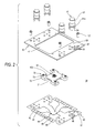
- Fig. 2 is an exploded perspective view of the contact unit 30, as seen from the above.
- Fig. 3 is an exploded perspective view of an inspection jig 1 in the embodiment according to the invention, as seen from the below.
- Fig. 4 is an exploded perspective view of the inspection jig 1, as seen from the above.
- Fig. 5 is a perspective view of the inspection jig 1 in which a unit pressing member 90 is omitted, as seen from the below.
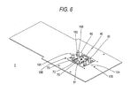
- Fig. 6 is a perspective view of the inspection jig 1 in which the unit pressing member 90 is omitted, as seen from the above.
- Fig. 1 is an exploded perspective view of a contact unit 30 in an embodiment according to the invention, as seen from the below.
- Fig. 2 is an exploded perspective view of the contact unit 30, as seen from the above.
- Fig. 3 is an exploded perspective
- FIG. 7 is a plan view of the inspection jig 1.
- Fig. 8 is a sectional view taken along a line A-A in Fig. 7 .
- Fig. 9 is a sectional view taken along a line B-B in Fig. 7 .
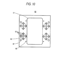
- Fig. 10 is a plan view of a sub board 60 in the contact unit 30.
- Fig. 11 is a plan view of a flexible board 40 in the contact unit 30, in which conductor patterns are shown in phantom. In Fig. 11 , the conductor patterns which are formed on a lower face of the flexible board 40 are shown in phantom from an upper face side of the flexible board 40.
- Fig. 12 is a partly enlarged plan view of a main board 10 in the inspection jig 1.
- Fig. 13 is an enlarged sectional view of a region surrounding an elastic member 92 in the inspection jig 1.
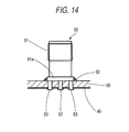
- Fig. 14 is an enlarged sectional view of a region surrounding a coaxial connector 50 in
- the contact unit 30 is an exchangeable contact unit for an inspection jig such as a probe card, and detachably fixed to the main board 10 of the inspection jig 1, as shown in Figs. 3 , 4 , and so on.
- the contact unit 30 includes the flexible board 40, four pieces of the coaxial connector 50 such as an SMA connector, the sub board 60 formed of a hard board such as a glass epoxy board, and a block 70 formed of, for example, a resin molded body.
- the flexible board 40 is provided for coming into contact with an object to be inspected such as a wafer.
- the flexible board 40 is positioned on one face (a lower face) of the sub board 60.
- a contact part 41 ( Fig. 1 ) to be contacted with the object to be inspected such as the wafer, signal patterns 42 ( Fig. 11 ), ground patterns 43 ( Fig. 11 ), and DC patterns 44 ( Fig. 11 ) are provided on a lower face (the face at an opposite side to the sub board 60) of the flexible board 40.
- through holes 45, connector leg passing holes 46, screw fastening holes 47, 48, and positioning holes 49 are formed in the flexible board 40. It is to be noted that the signal patterns 42 and the DC patterns 44 which are shown in Fig.
- the contact part 41 is an assembly of bumps for signal and DC, and positioned at a center of a cross-shaped part of the flexible board 40. Respective one ends of the signal patterns 42 and the DC patterns 44 are merged into the bumps of the contact part 41. The other ends of the signal patterns 42 are directly and electrically connected to leg portions 52 for signal of the coaxial connectors 50 by soldering or so. There are provided the signal patterns 42 of the same number as that of the coaxial connectors 50. The other ends of the DC patterns 44 are merged into the through holes 45.
- the ground patterns 43 are so formed as to extend up to the connector leg passing holes 46 through which leg portions for ground of the coaxial connectors 50 are passed, and the screw fastening holes 47 which are arranged near the connector leg passing holes 46, on the lower face (the face opposed to the main board 10) of the flexible board 40, to be electrically connected with the leg portions 53 for ground of the coaxial connectors 50.
- respective one part of the ground patterns 43 are provided up to a region near the contact part 41 in a manner of forming coplanar lines along with both sides of the signal patterns 42 which are extended up to the contact part 41.
- the through holes 45 are provided for establishing electrical connection between the DC patterns 44 and the main board 10.
- the connector leg passing holes 46 are formed for allowing the leg portions 52 for signal and the leg portions 53 for ground of the coaxial connectors 50 to pass through.
- the screw fastening holes 47 are formed for allowing screws (fastening components) 107 for fixing the contact unit 30 to the main board 10 in the inspection jig 1 to pass through. It is to be noted that the screws 107 which are shown in Figs. 1 and 2 are not necessarily constituent elements of the contact unit 30.
- the screw fastening holes 48 are provided for allowing screws (fastening components) 108 for fixing the unit pressing member 90 of the inspection jig 1 to the main board 10 to pass through.
- the screw fastening holes 48 are respectively provided at both sides of the through holes 45.
- the positioning holes 49 are provided for allowing positioning pins 109 ( Fig. 4 ) for positioning the contact unit 30 with respect to the main board 10 to pass through.
- the positioning holes 49 are provided adjacent to the screw fastening holes 48.
- the four coaxial connectors 50 are so positioned as to surround the contact part 41 of the flexible board 40, and directly and electrically connected to the flexible board 40.
- Coaxial cables which are extended from an inspection apparatus (a tester), which is not shown, can be detachably connected to the coaxial connectors 50.
- Each of the coaxial connectors 50 includes a main body 51, a single leg portion 52 for signal, and four leg portions 53 for ground.
- One end of the coaxial cable is connected to the inspection apparatus, and the other end thereof is detachably connected (attached) to the body part 51.
- the body part 51 is positioned on the other face (an upper face) of the sub board 60.
- a flange part 51a of the body part 51 is fixed to a connector fixing land 62 (omitted in Fig.
- the leg portion 52 for signal and the leg portions 53 for ground are extended from the body part 51, pass through connector leg passing holes 66 in the sub board 60 and the connector leg passing holes 46 in the flexible board 40, and then, directly and electrically connected to the face of the flexible board 40 at an opposite side to the sub board 60 by soldering or so ( Fig. 14 ).
- the leg portion 52 for signal is directly and electrically connected to the signal patterns 42 of the flexible board 40
- the leg portions 53 for ground are directly and electrically connected to the ground patterns 43 of the flexible board 40.
- the sub board 60 as a support board (a hard board) is provided for the purpose of preventing a large load from being applied to a bonded part (a soldered part) between the flexible board 40 and the coaxial connector 50, on occasion of attaching or detaching the coaxial cable to the coaxial connector 50.
- the sub board 60 is provided with a center through hole 61, the connector fixing lands 62 ( Fig. 10 ), the connector leg passing holes 66, screw fastening holes 67, and positioning holes 69.
- the center through hole 61 provides a space for arranging the block 70.
- the connector fixing lands 62 are provided on the upper face of the sub board 60 for the purpose of fixing the coaxial connector 50 by soldering or so.
- the connector leg passing holes 66 are provided for the purpose of inserting the leg portions 52 for signal and the leg portions 53 for ground of the coaxial connectors 50.
- the screw fastening holes 67 are provided for the purpose of passing the screws 107 for fixing the contact unit 30 to the main board 10 of the inspection jig 1.
- the positioning holes 69 are provided for the purpose of inserting the positioning pins 109 ( Fig. 4 ) for positioning the contact unit 30 to the main board 10.
- the block 70 is urged downward by a spring 91, in a state incorporated in the inspection jig 1, thereby to hold the flexible board 40 in such a state that the contact part 41 is protruded downward from the main board 10.
- the block 70 has four leg portions 72 around a center pyramid part 71 which is convexed downward.
- Parallelism adjusting screws 73 are respectively attached to the leg portions 72 of the block 70. Tip ends of the parallelism adjusting screws 73 are contacted with a base part 22 for block of a retainer 20 which will be described below.
- Vertical position of the block 70 which is urged by the spring 91 is determined, when the tip ends of the parallelism adjusting screws 73 come into contact with the base part 22 for block of the retainer 20.
- the positioning pins 103 are held by the block 70 to be projected upward.
- the positioning pins 103 has a function of positioning the unit pressing member 90, which will be described below, with respect to the contact unit 30.
- the spring 91 is shown at an upper side than the block 70 in Fig. 2 , the spring 91 may be held by the unit pressing member 90 of the inspection jig 1 by bonding or so, and need not be absolutely a constituent element of the contact unit 30.
- the inspection jig 1 is a probe card, for example, and used for inspecting electrical performance of a semiconductor integrated circuit in a state of a wafer.
- the inspection jig 1 includes the main board 10 formed of, for example, glass epoxy board, the retainer 20 formed of metal such as stainless steel or the like, the above described contact unit 30, and the unit pressing member 90 formed of, for example, a resin molded body.
- the main board 10 is provided with a through hole 11 for contact, through holes 15, connector leg passing holes 16, screw fastening holes 17, 18, and positioning holes 19 ( Fig. 12 ).
- the through hole 11 for contact is provided for the purpose of allowing the contact part 41 of the flexible board 40 to protrude downward.
- the through holes 15 are provided for establishing electrical connection with the through holes 45 which form the one ends of the DC patterns 44 of the flexible board 40.
- the connector leg passing holes 16 are provided for the purpose of avoiding the leg portions 52 for signal and the leg portions 53 for ground of the coaxial connectors 50.
- the screw fastening holes 17 are provided for the purpose of passing the screws 107 for fixing the contact unit 30 to the main board 10.
- the screw fastening holes 18 are provided for the purpose of passing the screws 108 for fixing the unit pressing member 90 to the main board 10.
- the positioning holes 19 as shown in Fig. 12 are provided for the purpose of passing the positioning pins 109 ( Fig. 4 ) for positioning the contact unit 30 with respect to the main board 10.
- Ground patterns 13 are provided on the upper face (the face opposed to the flexible board 40) of the main board 10 around the connector leg passing holes 16 and the screw fastening holes 17. By fastening the contact unit 30 to the main board 10 with the screws 107, the ground patterns 13 of the main board 10 and the ground patterns 43 of the flexible board 40 come into face contact with each other.
- the ground patterns 13, 43 are provided around the screw fastening holes 17, 47, and hence, the ground patterns 13, 43 are firmly brought into face contact with each other, particularly in regions around the positions where they are fastened with the screws 107.
- the retainer 20 is a thin sheet metal, for example, and has a function of restricting a downwardly protruding amount of the contact unit 30 from the main board 10.
- the retainer 20 is attached (fixed) to the lower face of the main board 10 with screws (fastening members) 106.
- the retainer 20 is provided with a through hole 21 for contact in a shape of a cross, and screw holes 27, 28.
- the base parts 22 for block ( Fig. 4 ) are formed around the through hole 21 for contact.
- the through hole 21 for contact is provided for the purpose of allowing the contact part 41 of the flexible board 40 to protrude downward.
- the screw holes 27 are adapted to be engaged with the screws 107 for fixing the contact unit 30 to the main board 10 of the inspection jig 1.
- the screw holes 28 are adapted to be engaged with the screws 108 for fixing the unit pressing member 90 to the main board 10.
- the base parts 22 for block are respectively positioned below the leg portions 72 of the block 70, and receive (support) the tip ends of the parallelism adjusting screws 73 which are attached to the leg portions 72 and extended downward from the leg portions 72.
- Positioning pins 104 and the aforesaid positioning pins 109 are provided on the retainer 20 and projected upward from the upper face of the main board 10.
- the positioning pins 104 have a function of positioning the unit pressing member 90 with respect to the main board 10.
- the positioning pins 109 have a function of positioning the contact unit 30 with respect to the main board 10.
- the main board 10 and the retainer 20 compose the main body of the inspection jig 1.
- the unit pressing member 90 is a member for pressing the contact unit 30 from the above.
- the unit pressing member 90 is provided with positioning holes 93, 94, connector body passing holes 95, and a recess 96 for spring ( Fig. 3 ).
- the positioning holes 93 are provided for the purpose of passing the positioning pins 103 for positioning the unit pressing member 90 with respect to the contact unit 30.
- the positioning holes 94 are provided for the purpose of passing the positioning pins 104 for positioning the unit pressing member 90 with respect to the main board 10.
- the connector body passing holes 95 are provided for the purpose of protruding the body parts 51 of the coaxial connectors 50 upward.
- the recess 96 for spring is provided for the purpose of supporting one end of the spring 91 which is shown in Fig. 2 .
- the spring 91 urges the block 70 downward (that is, urges the contact part 41 of the flexible board 40 downward) in a state where the unit pressing member 90 is fixed to the main board 10 with the screws 108, thereby to apply a contact force against the object to be inspected such as the wafer to the contact part 41 of the flexible board 40.
- Two pieces of the elastic member 92 ( Fig. 3 ) formed of silicone rubber or the like in a shape of a cord (a linear shape) are held on the lower face (the face opposed to the flexible board 40) of the unit pressing member 90.
- the elastic members 92 are provided at positions directly above the through holes 45 of the flexible board 40 and the through holes 15 of the main board 10, and press the through holes 45 of the flexible board 40 toward the through holes 15 of the main board 10, in a state where the unit pressing member 90 is fixed to the main board 10 with the screws 108.
- the screws 108 fix the unit pressing member 90 to the main board 10 at both sides of the elastic members 92 respectively, and hence, pressing effects by the elastic members 92 are enhanced.
- the through holes 15, 45 are brought into pressure contact with each other by the elastic members 92 thereby to be electrically connected.
- the contact unit 30 is assembled in advance. Specifically, the following steps are carried out.
- the leg portions 52 for signal and the leg portions 53 for ground of the coaxial connectors 50 are passed through the connector leg passing holes 66 in the sub board 60, and the flange parts 51a of the coaxial connectors 50 are fixed to the connector fixing lands 62 on the upper face of the sub board 60 by soldering or so.
- the leg portions 52 for signal and the leg portions 53 for ground of the coaxial connectors 50 are passed through the connector leg passing holes 46 in the flexible board 40 to which the block 70 has been already bonded
- the flexible board 40 is set on the lower face (the face at an opposite side to the face where the body parts 51 of the coaxial connectors 50 are fixed) of the sub board 60.
- leg portions 52 for signal and the leg portions 53 for ground of the coaxial connectors 50 are connected directly and electrically to the lower face (the face at the opposite side to the sub board 60) of the flexible board 40 by soldering or so. It is also possible to fix the flange parts 51a of the coaxial connectors 50 to the upper face of the sub board 60 (the connector fixing lands 62), after the leg portions 52 for signal and the leg portions 53 for ground of the coaxial connectors 50 have been electrically connected to the lower face of the flexible board 40 in advance.
- the flexible board 40 is indirectly fixed to the sub board 60, because the leg portions 52 for signal and the leg portions 53 for ground of the coaxial connectors 50 are fixed to the sub board 60 by soldering.
- the block 70 may be passed through the center through hole 61 of the sub board 60, and fixed to the back face of the contact part 41 of the flexible board 40 by bonding, in a final step.
- the contact unit 30 is attached (fixed) to the main board 10 with the screws 107.
- the four positioning pins 109 projected from the main board 10 are respectively passed through the positioning holes 49 in the flexible board 40 and the positioning holes 69 in the sub board 60.
- the four screws 107 are respectively passed through the screw fastening holes 67 in the sub board 60, the screw fastening holes 47 in the flexible board 40, and the screw fastening holes 17 in the main board 10, and screwed into the screw holes 27 in the retainer 20 which has been fixed to the lower face of the main board 10 in advance. In this manner, the flexible board 40 is clamped between the main board 10 and the sub board 60.
- the unit pressing member 90 is fixed to the main board 10 with the screws 108.
- the two positioning pins 103 which are projected upward from the block 70 and the two positioning pins 104 which are projected upward from the main board 10 are respectively passed through the positioning holes 93, 94 in the unit pressing member 90.
- the four screws 108 are passed through the screw fastening holes in the unit pressing member 90, the screw fastening holes 48 in the flexible board 40 and the screw fastening holes 18 in the main board 10, and screwed into the screw holes 28 in the retainer 20.
- the parallelism of the contact part 41 of the flexible board 40 is adjusted by turning the parallelism adjusting screws 73, according to necessity. In this manner, the assembling work of the inspection jig 1 is completed. It is to be noted that the contact unit 30 can be detached from the main board 10 by conducting the assembling steps in a reverse order.
- the contact unit 30 need not be provided with the sub board 60. In this case, the number of the components is reduced, although the contact unit 30 is weakened against the load which is applied on occasion of attaching or detaching the coaxial cables.
- parameters such as the number of the coaxial connectors 50, the number of the through holes, the number of the screws for fixing the respective parts, and the number of the positioning pins are not limited to the specific numbers which are described as examples in the embodiment, but can be optionally determined according to required performances and convenience in designing.
- the exchangeable contact unit which can be easily attached to or detached from the inspection jig such as a probe card, and can restrain deterioration of electrical performance in the inspection jig.
- the inspection jig in which the flexible board, which is a consumable supply, can be easily exchanged, while restraining deterioration of electrical performance.
Landscapes
- Physics & Mathematics (AREA)
- General Physics & Mathematics (AREA)
- Engineering & Computer Science (AREA)
- General Engineering & Computer Science (AREA)
- Computer Hardware Design (AREA)
- Microelectronics & Electronic Packaging (AREA)
- Measuring Leads Or Probes (AREA)
- Testing Or Measuring Of Semiconductors Or The Like (AREA)
Description
- The present invention relates to an exchangeable contact unit and an inspection jig such as a probe card which are used for inspecting electrical performance of a semiconductor integrated circuit, for example.
- An inspection jig such as a probe card which is used for inspecting electrical performance of a semiconductor integrated circuit includes a main board, and a flexible board which is bonded to the main board by soldering or so. The flexible board is provided with a contact part which is adapted to be contacted with an electrode of an object to be inspected (a wafer, for example). The flexible board is urged toward the object to be inspected from a back side of the contact part by means of a spring, thereby to be supplied with a contact force against the object to be inspected. The probe card having the above described structure is sometimes called as the probe card of a membrane type.
- On occasion of inspecting the electrical performance, electric signals at high frequency are transmitted between the inspection jig and the inspection apparatus (a tester) by way of a coaxial cable. The inspection jig is provided with a coaxial connector for detachably connecting the coaxial cable which is extended from the tester. The coaxial connector is electrically connected to the flexible board by soldering or so, and is fixed (bonded) to the main board by soldering or so.
- After contacts of about one million times, for example, have been repeated, the contact part of the flexible board wears, and the flexible board must be exchanged. In case where the flexible board and the main board are soldered to each other, the solder must be removed, when the flexible board is detached from the main board. Therefore, it requires technical skill and time to exchange the flexible board.
JP-A-2001-208777 - The coaxial connector is not referred to, in
JP-A-2001-208777 - The present invention has been made in view of the above described circumstances, and an object of the invention is to provide an exchangeable contact unit which can be easily attached to or detached from an inspection jig such as a probe card, but can restrain deterioration of electrical performance in the inspection jig.
- Another object of the invention is to provide an inspection jig in which a flexible board, which is a consumable supply, can be easily exchanged, while restraining deterioration of electrical performance.
- According to the invention, in order to achieve the object, there is provided an exchangeable contact unit which can be attached to or detached from a main body of an inspection jig, the exchangeable contact unit comprising: a flexible board which is provided with a contact part with respect to an object to be inspected; and a coaxial connector which is directly and electrically connected to the flexible board.
- The exchangeable contact unit may further comprise: a support board to which the coaxial connector is fixed.
- The flexible board may be positioned on one face side of the support board, the coaxial connector may include: a body part which is positioned on the other face side of the support board; and a leg portion which is extended from the body part to pass through the support board and the flexible board, and which is electrically connected to the flexible board, and the contact unit may be detachably fixed to the main body of the inspection jig in such a manner that the flexible board is clamped between a board of the inspection jig and the support board.
- A ground pattern which is electrically connected to a leg portion for ground of the coaxial connector may be provided on a face of the flexible board at an opposite side to the support board and extended up to a region around a through hole for fixing the flexible board to the main body of the inspection jig.
- According to the invention, in order to achieve the object, there is provided an inspection jig comprising: a contact unit which includes: a flexible board provided with a contact part to be contacted with an object to be inspected; and a coaxial connector which is directly and electrically connected to the flexible board; a main board to which the contact unit is detachably fixed; and an urging member which is configured to apply a contact force with respect to the object to be inspected to the contact part, wherein the flexible board and the coaxial connector are not bonded to the main board.
- The contact unit may be provided with a support board, and the coaxial connector may be fixed to the support board.
- The flexible board may be clamped between the main board and the support board.
- The main board, the flexible board and the support board may be fixed to each other by fastening components, ground patterns for the coaxial connector may be respectively provided on faces of the main board and the flexible board which are opposed to each other, so as to extend around fixed positions where they are fixed by the fastening components, and the ground patterns may be in face contact with each other, in regions around the fixed positions.
- The inspection jig may further comprise: a unit pressing member which is fixed to the main board and is configured to support one end of the urging member. The flexible board may be positioned between the main board and the unit pressing member, and the unit pressing member may be provided with an elastic member for pressing the flexible board against the main board thereby to electrically connect them to each other.
- The unit pressing member may be fixed to the main board by fastening components at both sides of the elastic member.
- It is to be noted that optional combinations of the above described constituent elements, and descriptions of the present invention which are converted between methods and systems are also effective as features of the invention.
-
-
Fig. 1 is an exploded perspective view of acontact unit 30 in an embodiment according to the invention, as seen from the below. -
Fig. 2 is an exploded perspective view of thecontact unit 30, as seen from the above. -
Fig. 3 is an exploded perspective view of aninspection jig 1 in the embodiment according to the invention, as seen from the below. -
Fig. 4 is an exploded perspective view of theinspection jig 1, as seen from the above. -
Fig. 5 is a perspective view of theinspection jig 1 in which aunit pressing member 90 is omitted, as seen from the below. -
Fig. 6 is a perspective view of theinspection jig 1 in which theunit pressing member 90 is omitted, as seen from the above. -
Fig. 7 is a plan view of theinspection jig 1. -
Fig. 8 is a sectional view taken along a line A-A inFig. 7 . -
Fig. 9 is a sectional view taken along a line B-B inFig. 7 . -
Fig. 10 is a plan view of asub board 60 in thecontact unit 30. -
Fig. 11 is a plan view of aflexible board 40 in thecontact unit 30, in which conductor patterns are shown in phantom. -
Fig. 12 is a partly enlarged plan view of amain board 10 in theinspection jig 1. -
Fig. 13 is an enlarged sectional view of a region surrounding anelastic member 92 in theinspection jig 1. -
Fig. 14 is an enlarged sectional view of a region surrounding acoaxial connector 50 in thecontact unit 30. - Now, a preferred embodiment of the invention will be described in detail, referring to the drawings. It is to be noted that the same or equivalent constituent elements, members and so on which are shown in the respective drawings are denoted with the same reference numerals, and overlapped descriptions are appropriately omitted. Moreover, the invention is not limited to the embodiment, but the embodiment is only an example, and all features and combinations of the features which are described in the embodiment are not absolutely essential to the invention.
-
Fig. 1 is an exploded perspective view of acontact unit 30 in an embodiment according to the invention, as seen from the below.Fig. 2 is an exploded perspective view of thecontact unit 30, as seen from the above.Fig. 3 is an exploded perspective view of aninspection jig 1 in the embodiment according to the invention, as seen from the below.Fig. 4 is an exploded perspective view of theinspection jig 1, as seen from the above.Fig. 5 is a perspective view of theinspection jig 1 in which aunit pressing member 90 is omitted, as seen from the below.Fig. 6 is a perspective view of theinspection jig 1 in which theunit pressing member 90 is omitted, as seen from the above.Fig. 7 is a plan view of theinspection jig 1.Fig. 8 is a sectional view taken along a line A-A inFig. 7 .Fig. 9 is a sectional view taken along a line B-B inFig. 7 .Fig. 10 is a plan view of asub board 60 in thecontact unit 30.Fig. 11 is a plan view of aflexible board 40 in thecontact unit 30, in which conductor patterns are shown in phantom. InFig. 11 , the conductor patterns which are formed on a lower face of theflexible board 40 are shown in phantom from an upper face side of theflexible board 40.Fig. 12 is a partly enlarged plan view of amain board 10 in theinspection jig 1.Fig. 13 is an enlarged sectional view of a region surrounding anelastic member 92 in theinspection jig 1.Fig. 14 is an enlarged sectional view of a region surrounding acoaxial connector 50 in thecontact unit 30. - The
contact unit 30 is an exchangeable contact unit for an inspection jig such as a probe card, and detachably fixed to themain board 10 of theinspection jig 1, as shown inFigs. 3 ,4 , and so on. Thecontact unit 30 includes theflexible board 40, four pieces of thecoaxial connector 50 such as an SMA connector, thesub board 60 formed of a hard board such as a glass epoxy board, and ablock 70 formed of, for example, a resin molded body. - The
flexible board 40 is provided for coming into contact with an object to be inspected such as a wafer. Theflexible board 40 is positioned on one face (a lower face) of thesub board 60. A contact part 41 (Fig. 1 ) to be contacted with the object to be inspected such as the wafer, signal patterns 42 (Fig. 11 ), ground patterns 43 (Fig. 11 ), and DC patterns 44 (Fig. 11 ) are provided on a lower face (the face at an opposite side to the sub board 60) of theflexible board 40. Moreover, throughholes 45, connectorleg passing holes 46, screw fastening holes 47, 48, and positioning holes 49 are formed in theflexible board 40. It is to be noted that thesignal patterns 42 and theDC patterns 44 which are shown inFig. 11 are omitted in the other drawings containing theflexible board 40, exceptFig. 11 . Moreover, theground patterns 43 are omitted in the other drawings containing theflexible board 40, exceptFig. 3 andFig. 11 . When thecontact unit 30 is attached to theinspection jig 1, theflexible board 40 is not bonded to the below describedmain board 10 by soldering. - The
contact part 41 is an assembly of bumps for signal and DC, and positioned at a center of a cross-shaped part of theflexible board 40. Respective one ends of thesignal patterns 42 and theDC patterns 44 are merged into the bumps of thecontact part 41. The other ends of thesignal patterns 42 are directly and electrically connected toleg portions 52 for signal of thecoaxial connectors 50 by soldering or so. There are provided thesignal patterns 42 of the same number as that of thecoaxial connectors 50. The other ends of theDC patterns 44 are merged into the through holes 45. Theground patterns 43 are so formed as to extend up to the connectorleg passing holes 46 through which leg portions for ground of thecoaxial connectors 50 are passed, and the screw fastening holes 47 which are arranged near the connectorleg passing holes 46, on the lower face (the face opposed to the main board 10) of theflexible board 40, to be electrically connected with theleg portions 53 for ground of thecoaxial connectors 50. Although not shown inFig. 11 , respective one part of theground patterns 43 are provided up to a region near thecontact part 41 in a manner of forming coplanar lines along with both sides of thesignal patterns 42 which are extended up to thecontact part 41. The through holes 45 are provided for establishing electrical connection between theDC patterns 44 and themain board 10. - The connector
leg passing holes 46 are formed for allowing theleg portions 52 for signal and theleg portions 53 for ground of thecoaxial connectors 50 to pass through. The screw fastening holes 47 are formed for allowing screws (fastening components) 107 for fixing thecontact unit 30 to themain board 10 in theinspection jig 1 to pass through. It is to be noted that thescrews 107 which are shown inFigs. 1 and2 are not necessarily constituent elements of thecontact unit 30. The screw fastening holes 48 are provided for allowing screws (fastening components) 108 for fixing theunit pressing member 90 of theinspection jig 1 to themain board 10 to pass through. The screw fastening holes 48 are respectively provided at both sides of the through holes 45. The positioning holes 49 are provided for allowing positioning pins 109 (Fig. 4 ) for positioning thecontact unit 30 with respect to themain board 10 to pass through. The positioning holes 49 are provided adjacent to the screw fastening holes 48. - The four
coaxial connectors 50 are so positioned as to surround thecontact part 41 of theflexible board 40, and directly and electrically connected to theflexible board 40. Coaxial cables which are extended from an inspection apparatus (a tester), which is not shown, can be detachably connected to thecoaxial connectors 50. Each of thecoaxial connectors 50 includes amain body 51, asingle leg portion 52 for signal, and fourleg portions 53 for ground. One end of the coaxial cable is connected to the inspection apparatus, and the other end thereof is detachably connected (attached) to thebody part 51. Thebody part 51 is positioned on the other face (an upper face) of thesub board 60. Aflange part 51a of thebody part 51 is fixed to a connector fixing land 62 (omitted inFig. 2 ) of thesub board 60 which is shown inFig. 10 , by soldering or so (Fig. 14 ). Theleg portion 52 for signal and theleg portions 53 for ground are extended from thebody part 51, pass through connectorleg passing holes 66 in thesub board 60 and the connectorleg passing holes 46 in theflexible board 40, and then, directly and electrically connected to the face of theflexible board 40 at an opposite side to thesub board 60 by soldering or so (Fig. 14 ). Specifically, theleg portion 52 for signal is directly and electrically connected to thesignal patterns 42 of theflexible board 40, and theleg portions 53 for ground are directly and electrically connected to theground patterns 43 of theflexible board 40. When thecontact unit 30 is attached to theinspection jig 1, thecoaxial connectors 50 are not bonded to themain board 10, which will be described below, by soldering. - The
sub board 60 as a support board (a hard board) is provided for the purpose of preventing a large load from being applied to a bonded part (a soldered part) between theflexible board 40 and thecoaxial connector 50, on occasion of attaching or detaching the coaxial cable to thecoaxial connector 50. Thesub board 60 is provided with a center throughhole 61, the connector fixing lands 62 (Fig. 10 ), the connectorleg passing holes 66, screw fastening holes 67, and positioning holes 69. The center throughhole 61 provides a space for arranging theblock 70. The connector fixing lands 62 are provided on the upper face of thesub board 60 for the purpose of fixing thecoaxial connector 50 by soldering or so. The connectorleg passing holes 66 are provided for the purpose of inserting theleg portions 52 for signal and theleg portions 53 for ground of thecoaxial connectors 50. The screw fastening holes 67 are provided for the purpose of passing thescrews 107 for fixing thecontact unit 30 to themain board 10 of theinspection jig 1. The positioning holes 69 are provided for the purpose of inserting the positioning pins 109 (Fig. 4 ) for positioning thecontact unit 30 to themain board 10. - The
block 70 is urged downward by aspring 91, in a state incorporated in theinspection jig 1, thereby to hold theflexible board 40 in such a state that thecontact part 41 is protruded downward from themain board 10. Theblock 70 has fourleg portions 72 around acenter pyramid part 71 which is convexed downward. Parallelism adjusting screws 73 are respectively attached to theleg portions 72 of theblock 70. Tip ends of the parallelism adjusting screws 73 are contacted with a base part 22 for block of aretainer 20 which will be described below. Vertical position of theblock 70 which is urged by thespring 91 is determined, when the tip ends of the parallelism adjusting screws 73 come into contact with the base part 22 for block of theretainer 20. Two positioningpins 103 are held by theblock 70 to be projected upward. The positioning pins 103 has a function of positioning theunit pressing member 90, which will be described below, with respect to thecontact unit 30. Although thespring 91 is shown at an upper side than theblock 70 inFig. 2 , thespring 91 may be held by theunit pressing member 90 of theinspection jig 1 by bonding or so, and need not be absolutely a constituent element of thecontact unit 30. - The
inspection jig 1 is a probe card, for example, and used for inspecting electrical performance of a semiconductor integrated circuit in a state of a wafer. Theinspection jig 1 includes themain board 10 formed of, for example, glass epoxy board, theretainer 20 formed of metal such as stainless steel or the like, the above describedcontact unit 30, and theunit pressing member 90 formed of, for example, a resin molded body. - The
main board 10 is provided with a throughhole 11 for contact, throughholes 15, connectorleg passing holes 16, screw fastening holes 17, 18, and positioning holes 19 (Fig. 12 ). The throughhole 11 for contact is provided for the purpose of allowing thecontact part 41 of theflexible board 40 to protrude downward. The through holes 15 are provided for establishing electrical connection with the throughholes 45 which form the one ends of theDC patterns 44 of theflexible board 40. The connectorleg passing holes 16 are provided for the purpose of avoiding theleg portions 52 for signal and theleg portions 53 for ground of thecoaxial connectors 50. The screw fastening holes 17 are provided for the purpose of passing thescrews 107 for fixing thecontact unit 30 to themain board 10. The screw fastening holes 18 are provided for the purpose of passing thescrews 108 for fixing theunit pressing member 90 to themain board 10. The positioning holes 19 as shown inFig. 12 are provided for the purpose of passing the positioning pins 109 (Fig. 4 ) for positioning thecontact unit 30 with respect to themain board 10.Ground patterns 13 are provided on the upper face (the face opposed to the flexible board 40) of themain board 10 around the connectorleg passing holes 16 and the screw fastening holes 17. By fastening thecontact unit 30 to themain board 10 with thescrews 107, theground patterns 13 of themain board 10 and theground patterns 43 of theflexible board 40 come into face contact with each other. Theground patterns ground patterns screws 107. - The
retainer 20 is a thin sheet metal, for example, and has a function of restricting a downwardly protruding amount of thecontact unit 30 from themain board 10. Theretainer 20 is attached (fixed) to the lower face of themain board 10 with screws (fastening members) 106. Theretainer 20 is provided with a throughhole 21 for contact in a shape of a cross, and screwholes Fig. 4 ) are formed around the throughhole 21 for contact. The throughhole 21 for contact is provided for the purpose of allowing thecontact part 41 of theflexible board 40 to protrude downward. The screw holes 27 are adapted to be engaged with thescrews 107 for fixing thecontact unit 30 to themain board 10 of theinspection jig 1. The screw holes 28 are adapted to be engaged with thescrews 108 for fixing theunit pressing member 90 to themain board 10. The base parts 22 for block are respectively positioned below theleg portions 72 of theblock 70, and receive (support) the tip ends of the parallelism adjusting screws 73 which are attached to theleg portions 72 and extended downward from theleg portions 72. Positioning pins 104 and the aforesaid positioning pins 109 are provided on theretainer 20 and projected upward from the upper face of themain board 10. The positioning pins 104 have a function of positioning theunit pressing member 90 with respect to themain board 10. The positioning pins 109 have a function of positioning thecontact unit 30 with respect to themain board 10. Themain board 10 and theretainer 20 compose the main body of theinspection jig 1. - The
unit pressing member 90 is a member for pressing thecontact unit 30 from the above. Theunit pressing member 90 is provided withpositioning holes body passing holes 95, and arecess 96 for spring (Fig. 3 ). The positioning holes 93 are provided for the purpose of passing the positioning pins 103 for positioning theunit pressing member 90 with respect to thecontact unit 30. The positioning holes 94 are provided for the purpose of passing the positioning pins 104 for positioning theunit pressing member 90 with respect to themain board 10. The connectorbody passing holes 95 are provided for the purpose of protruding thebody parts 51 of thecoaxial connectors 50 upward. Therecess 96 for spring is provided for the purpose of supporting one end of thespring 91 which is shown inFig. 2 . Thespring 91 urges theblock 70 downward (that is, urges thecontact part 41 of theflexible board 40 downward) in a state where theunit pressing member 90 is fixed to themain board 10 with thescrews 108, thereby to apply a contact force against the object to be inspected such as the wafer to thecontact part 41 of theflexible board 40. Two pieces of the elastic member 92 (Fig. 3 ) formed of silicone rubber or the like in a shape of a cord (a linear shape) are held on the lower face (the face opposed to the flexible board 40) of theunit pressing member 90. Theelastic members 92 are provided at positions directly above the throughholes 45 of theflexible board 40 and the throughholes 15 of themain board 10, and press the throughholes 45 of theflexible board 40 toward the throughholes 15 of themain board 10, in a state where theunit pressing member 90 is fixed to themain board 10 with thescrews 108. Thescrews 108 fix theunit pressing member 90 to themain board 10 at both sides of theelastic members 92 respectively, and hence, pressing effects by theelastic members 92 are enhanced. The through holes 15, 45 are brought into pressure contact with each other by theelastic members 92 thereby to be electrically connected. - A flow of an assembling work of the
inspection jig 1 will be described below. - As a first step, the
contact unit 30 is assembled in advance. Specifically, the following steps are carried out. Theleg portions 52 for signal and theleg portions 53 for ground of thecoaxial connectors 50 are passed through the connectorleg passing holes 66 in thesub board 60, and theflange parts 51a of thecoaxial connectors 50 are fixed to the connector fixing lands 62 on the upper face of thesub board 60 by soldering or so. Thereafter, while theleg portions 52 for signal and theleg portions 53 for ground of thecoaxial connectors 50 are passed through the connectorleg passing holes 46 in theflexible board 40 to which theblock 70 has been already bonded, theflexible board 40 is set on the lower face (the face at an opposite side to the face where thebody parts 51 of thecoaxial connectors 50 are fixed) of thesub board 60. Then, theleg portions 52 for signal and theleg portions 53 for ground of thecoaxial connectors 50 are connected directly and electrically to the lower face (the face at the opposite side to the sub board 60) of theflexible board 40 by soldering or so. It is also possible to fix theflange parts 51a of thecoaxial connectors 50 to the upper face of the sub board 60 (the connector fixing lands 62), after theleg portions 52 for signal and theleg portions 53 for ground of thecoaxial connectors 50 have been electrically connected to the lower face of theflexible board 40 in advance. Theflexible board 40 is indirectly fixed to thesub board 60, because theleg portions 52 for signal and theleg portions 53 for ground of thecoaxial connectors 50 are fixed to thesub board 60 by soldering. In this manner, the assembling work of thecontact unit 30 is completed. It is to be noted that theblock 70 may be passed through the center throughhole 61 of thesub board 60, and fixed to the back face of thecontact part 41 of theflexible board 40 by bonding, in a final step. - Then, the
contact unit 30 is attached (fixed) to themain board 10 with thescrews 107. Specifically, the fourpositioning pins 109 projected from themain board 10 are respectively passed through the positioning holes 49 in theflexible board 40 and the positioning holes 69 in thesub board 60. At the same time, the fourscrews 107 are respectively passed through the screw fastening holes 67 in thesub board 60, the screw fastening holes 47 in theflexible board 40, and the screw fastening holes 17 in themain board 10, and screwed into the screw holes 27 in theretainer 20 which has been fixed to the lower face of themain board 10 in advance. In this manner, theflexible board 40 is clamped between themain board 10 and thesub board 60. - Then, the
unit pressing member 90 is fixed to themain board 10 with thescrews 108. Specifically, the twopositioning pins 103 which are projected upward from theblock 70 and the twopositioning pins 104 which are projected upward from themain board 10 are respectively passed through the positioning holes 93, 94 in theunit pressing member 90. At the same time, the fourscrews 108 are passed through the screw fastening holes in theunit pressing member 90, the screw fastening holes 48 in theflexible board 40 and the screw fastening holes 18 in themain board 10, and screwed into the screw holes 28 in theretainer 20. The parallelism of thecontact part 41 of theflexible board 40 is adjusted by turning the parallelism adjusting screws 73, according to necessity. In this manner, the assembling work of theinspection jig 1 is completed. It is to be noted that thecontact unit 30 can be detached from themain board 10 by conducting the assembling steps in a reverse order. - According to this embodiment, the following advantages can be obtained.
- (1) Because the
coaxial connectors 50 are directly and electrically connected to thesignal patterns 42 of theflexible board 40 which has thecontact part 41 with respect to the object to be inspected such as the wafer, it is possible to transmit the electric signals at high frequency without electrical connection by the pressure contact between themain board 10 and theflexible board 40, and hence, it is possible to restrain deterioration of the electrical performance. Therefore, it is possible to realize thecontact unit 30 capable of restraining deterioration of the electrical performance in theinspection jig 1, and theinspection jig 1 capable of restraining deterioration of the electrical performance. - (2) The
contact unit 30 is attached (fixed) to themain board 10 with thescrews 107 which pass through thesub board 60 and theflexible board 40, and on the other hand, theflexible board 40 and thecoaxial connectors 50 are not bonded to themain board 10 by soldering or so. Therefore, the exchanging (attaching or detaching) work of thecontact unit 30 is easily carried out, because thescrews 107 have only to be attached or detached on occasion of exchanging thecontact unit 30, and the solders need not be removed. As the results, it is possible to realize thecontact unit 30 which can be easily attached to or detached from the main body of theinspection jig 1, and theinspection jig 1 in which theflexible board 40, which is the consumable supply, can be easily exchanged. - (3) Because the
coaxial connectors 50 are fixed to thesub board 60 by soldering or so, it is possible to prevent a large load from being applied to the bonded parts (the soldered parts) between theflexible board 40 and thecoaxial connectors 50, on occasion of attaching or detaching the coaxial cables. In this connection, in case where thecoaxial connectors 50 are fixed to themain board 10 by soldering or so, easiness in attaching or detaching thecontact unit 30 is hindered. However, it is possible to secure the easiness in attaching or detaching thecontact unit 30, by fixing thecoaxial connectors 50, by soldering or so, to thesub board 60 which is provided separately from themain board 10. Moreover, in case where thecoaxial connectors 50 are fixed to themain board 10 by screwing or so, the large flange parts are required, and this is unrealistic from a view point of space securing. However, it is possible to firmly fix thecoaxial connectors 50 to themain board 10 within a limited space, by fixing them to thesub board 60 by soldering or so. - (4) Because the
ground patterns 13 of themain board 10 and theground patterns 43 of theflexible board 40 are extended up to the regions around the screw fastening holes 17, 47, it is possible to forcibly bring theground patterns screws 107, by clamping theflexible board 40 between themain board 10 and thesub board 60. As the results, the electrical connection between theleg portions 53 for ground of thecoaxial connectors 50 and theground patterns 13 of themain board 10 can be easily and reliably performed. - (5) Because the
elastic members 92 which are provided on theunit pressing member 90 press theflexible board 40 against themain board 10 thereby to bring the throughholes 45 in theflexible board 40 into pressure contact with the throughholes 15 in themain board 10, it is possible to electrically connect the throughholes screws 108 for fixing theunit pressing member 90 to themain board 10 are provided at both sides of theelastic members 92, theflexible board 40 can be pressed with theelastic members 92 with enhanced pressing effect. - The invention has been heretofore described referring to the embodiment as an example. However, it is to be understood by those skilled in the art that various modifications can be added to the constituent elements and the treating processes in the embodiment. The modifications will be briefly described below.
- It is also possible to use the
inspection jig 1 for inspecting the electrical performance of a semiconductor integrated circuit which is divided in individual parts. Thecontact unit 30 need not be provided with thesub board 60. In this case, the number of the components is reduced, although thecontact unit 30 is weakened against the load which is applied on occasion of attaching or detaching the coaxial cables. Besides, parameters such as the number of thecoaxial connectors 50, the number of the through holes, the number of the screws for fixing the respective parts, and the number of the positioning pins are not limited to the specific numbers which are described as examples in the embodiment, but can be optionally determined according to required performances and convenience in designing. - According to an aspect of the invention, it is possible to provide the exchangeable contact unit which can be easily attached to or detached from the inspection jig such as a probe card, and can restrain deterioration of electrical performance in the inspection jig.
- According to an aspect of the invention, it is possible to provide the inspection jig in which the flexible board, which is a consumable supply, can be easily exchanged, while restraining deterioration of electrical performance.
Claims (10)
- An exchangeable contact unit which can be attached to or detached from a main body of an inspection jig, the exchangeable contact unit comprising:a flexible board which is provided with a contact part with respect to an object to be inspected; anda coaxial connector which is directly and electrically connected to the flexible board.
- The exchangeable contact unit according to claim 1, further comprising: a support board to which the coaxial connector is fixed.
- The exchangeable contact unit according to claim 2, wherein
the flexible board is positioned on one face side of the support board,
the coaxial connector includes: a body part which is positioned on the other face side of the support board; and a leg portion which is extended from the body part to pass through the support board and the flexible board, and which is electrically connected to the flexible board, and
the contact unit is detachably fixed to the main body of the inspection jig in such a manner that the flexible board is clamped between a board of the inspection jig and the support board. - The exchangeable contact unit according to claim 3, wherein a ground pattern which is electrically connected to a leg portion for ground of the coaxial connector is provided on a face of the flexible board at an opposite side to the support board and extended up to a region around a through hole for fixing the flexible board to the main body of the inspection jig.
- An inspection jig comprising:a contact unit which includes: a flexible board provided with a contact part to be contacted with an object to be inspected; and a coaxial connector which is directly and electrically connected to the flexible board;a main board to which the contact unit is detachably fixed; andan urging member which is configured to apply a contact force with respect to the object to be inspected to the contact part, whereinthe flexible board and the coaxial connector are not bonded to the main board.
- The inspection jig according to claim 5, wherein the contact unit is provided with a support board, and the coaxial connector is fixed to the support board.
- The inspection jig according to claim 6, wherein the flexible board is clamped between the main board and the support board.
- The inspection jig according to claim 7, wherein
the main board, the flexible board and the support board are fixed to each other by fastening components,
ground patterns for the coaxial connector are respectively provided on faces of the main board and the flexible board which are opposed to each other, so as to extend around fixed positions where they are fixed by the fastening components, and
the ground patterns are in face contact with each other, in regions around the fixed positions. - The inspection jig according to any one of claims 5 to 8, further comprising: a unit pressing member which is fixed to the main board and is configured to support one end of the urging member, wherein
the flexible board is positioned between the main board and the unit pressing member, and
the unit pressing member is provided with an elastic member for pressing the flexible board against the main board thereby to electrically connect them to each other. - The inspection jig according to claim 9, wherein the unit pressing member is fixed to the main board by fastening components at both sides of the elastic member.
Applications Claiming Priority (1)
| Application Number | Priority Date | Filing Date | Title |
|---|---|---|---|
| JP2014265836A JP6496142B2 (en) | 2014-12-26 | 2014-12-26 | Replacement contact unit and inspection jig |
Publications (2)
| Publication Number | Publication Date |
|---|---|
| EP3037834A1 true EP3037834A1 (en) | 2016-06-29 |
| EP3037834B1 EP3037834B1 (en) | 2019-02-20 |
Family
ID=55168097
Family Applications (1)
| Application Number | Title | Priority Date | Filing Date |
|---|---|---|---|
| EP15202446.9A Not-in-force EP3037834B1 (en) | 2014-12-26 | 2015-12-23 | Exchangeable contact unit and inspection jig |
Country Status (4)
| Country | Link |
|---|---|
| US (1) | US10393771B2 (en) |
| EP (1) | EP3037834B1 (en) |
| JP (1) | JP6496142B2 (en) |
| TW (1) | TWI639837B (en) |
Families Citing this family (11)
| Publication number | Priority date | Publication date | Assignee | Title |
|---|---|---|---|---|
| USD813171S1 (en) * | 2016-04-08 | 2018-03-20 | Abb Schweiz Ag | Cover for an electric connector |
| USD824859S1 (en) * | 2016-04-08 | 2018-08-07 | Abb Schweiz Ag | Electric connector |
| US10663486B2 (en) * | 2017-02-06 | 2020-05-26 | International Business Machines Corporation | Portable electrical noise probe structure |
| JP7240317B2 (en) * | 2017-07-24 | 2023-03-15 | 株式会社ヨコオ | Inspection jig |
| JP2020191170A (en) * | 2019-05-20 | 2020-11-26 | 日本航空電子工業株式会社 | Connector inspection device and connector module |
| CN111175636B (en) * | 2020-01-02 | 2022-09-13 | 广东科学技术职业学院 | Bonding testing circuit and bonding testing device |
| JP6901603B1 (en) * | 2020-03-27 | 2021-07-14 | 日本航空電子工業株式会社 | Board-to-board connector |
| JP7348131B2 (en) * | 2020-04-28 | 2023-09-20 | 日本航空電子工業株式会社 | board to board connector |
| CN112433098B (en) * | 2020-11-17 | 2026-01-02 | 沈阳兴华航空电器有限责任公司 | A self-calibrating RF button high-frequency performance testing fixture and testing method |
| CN115224566A (en) * | 2021-04-20 | 2022-10-21 | 康普技术有限责任公司 | Cable connector and manufacturing method thereof, cable assembly and circuit board assembly |
| KR102551965B1 (en) * | 2022-12-02 | 2023-07-06 | 주식회사 피엠티 | Probe Sheet With Contact Tip On Stacked Multi-Layer And Method Of Manufacturing The Same |
Citations (4)
| Publication number | Priority date | Publication date | Assignee | Title |
|---|---|---|---|---|
| JP2001183392A (en) * | 1999-12-27 | 2001-07-06 | Micronics Japan Co Ltd | Probe card |
| JP2001208777A (en) | 2000-01-24 | 2001-08-03 | Urex Precision Inc | Membrane probe card |
| US20060006892A1 (en) * | 2001-12-14 | 2006-01-12 | Green Roy W | Flexible test head internal interface |
| US20100127725A1 (en) * | 2008-11-21 | 2010-05-27 | Smith Kenneth R | Replaceable coupon for a probing apparatus |
Family Cites Families (29)
| Publication number | Priority date | Publication date | Assignee | Title |
|---|---|---|---|---|
| US3879103A (en) * | 1970-12-07 | 1975-04-22 | Tektronix Inc | Coaxial cable connector for circuit board |
| US4912399A (en) | 1987-06-09 | 1990-03-27 | Tektronix, Inc. | Multiple lead probe for integrated circuits in wafer form |
| JPH07109840B2 (en) * | 1989-03-10 | 1995-11-22 | 松下電器産業株式会社 | Semiconductor IC test apparatus and test method |
| US5559446A (en) * | 1993-07-19 | 1996-09-24 | Tokyo Electron Kabushiki Kaisha | Probing method and device |
| JP3382059B2 (en) * | 1995-04-28 | 2003-03-04 | 株式会社アドバンテスト | Semiconductor test equipment |
| US5752839A (en) * | 1995-06-30 | 1998-05-19 | Labinal Components And Systems, Inc. | Coaxial connector for press fit mounting |
| KR100471341B1 (en) * | 1996-05-23 | 2005-07-21 | 제네시스 테크놀로지 가부시키가이샤 | Contact Probe and Probe Device with It |
| JP2889562B1 (en) * | 1998-04-21 | 1999-05-10 | エスエムケイ株式会社 | Coaxial connector with switch |
| US6393607B1 (en) * | 1999-01-27 | 2002-05-21 | Scientific-Atlanta, Inc. | AC port device for cable television tap |
| JP3565086B2 (en) * | 1999-04-16 | 2004-09-15 | 富士通株式会社 | Probe card and method for testing semiconductor device |
| US6906539B2 (en) * | 2000-07-19 | 2005-06-14 | Texas Instruments Incorporated | High density, area array probe card apparatus |
| US6707311B2 (en) * | 2002-07-09 | 2004-03-16 | Advantest Corp. | Contact structure with flexible cable and probe contact assembly using same |
| US6621710B1 (en) * | 2002-07-19 | 2003-09-16 | Chipmos Technologies (Bermuda) Ltd. | Modular probe card assembly |
| US6924653B2 (en) * | 2002-08-26 | 2005-08-02 | Micron Technology, Inc. | Selectively configurable microelectronic probes |
| JP2004108898A (en) * | 2002-09-17 | 2004-04-08 | Advantest Corp | Performance board and test system |
| US7548082B2 (en) * | 2003-04-15 | 2009-06-16 | Nec Corporation | Inspection probe |
| US6853205B1 (en) * | 2003-07-17 | 2005-02-08 | Chipmos Technologies (Bermuda) Ltd. | Probe card assembly |
| US7477118B2 (en) * | 2005-01-20 | 2009-01-13 | Kyocera Corporation | High frequency device mounting substrate and communications apparatus |
| WO2007091329A1 (en) * | 2006-02-10 | 2007-08-16 | Fujitsu Limited | Electronic component package |
| JP2007305516A (en) * | 2006-05-15 | 2007-11-22 | Fujitsu Ltd | Coaxial connector, connector assembly, printed circuit board, and electronic device |
| JP2008082734A (en) * | 2006-09-26 | 2008-04-10 | Sony Corp | Electrical contact device, high frequency measurement system, and high frequency measurement method |
| JP4972418B2 (en) * | 2007-01-29 | 2012-07-11 | 株式会社アドバンテスト | Test equipment and probe card |
| US7699617B2 (en) * | 2007-10-08 | 2010-04-20 | Winchester Electronics Corporation | Modular interconnect apparatus |
| JP5504698B2 (en) * | 2009-06-02 | 2014-05-28 | 日本電産リード株式会社 | Inspection jig and contact for inspection |
| KR101768992B1 (en) * | 2010-12-30 | 2017-08-17 | 삼성전자주식회사 | Probe card and method of testing a semiconductor device |
| JP5533838B2 (en) * | 2011-11-04 | 2014-06-25 | 株式会社村田製作所 | Coaxial connector plug |
| JP5569548B2 (en) * | 2012-03-13 | 2014-08-13 | 第一精工株式会社 | Coaxial electrical connector and coaxial electrical connector device |
| US10024883B2 (en) * | 2015-03-27 | 2018-07-17 | Yokowo Co., Ltd. | Contact unit and inspection jig |
| JP6525831B2 (en) * | 2015-09-15 | 2019-06-05 | 株式会社ヨコオ | Contact unit and inspection jig |
-
2014
- 2014-12-26 JP JP2014265836A patent/JP6496142B2/en active Active
-
2015
- 2015-12-23 EP EP15202446.9A patent/EP3037834B1/en not_active Not-in-force
- 2015-12-25 TW TW104143761A patent/TWI639837B/en active
- 2015-12-28 US US14/979,905 patent/US10393771B2/en active Active
Patent Citations (4)
| Publication number | Priority date | Publication date | Assignee | Title |
|---|---|---|---|---|
| JP2001183392A (en) * | 1999-12-27 | 2001-07-06 | Micronics Japan Co Ltd | Probe card |
| JP2001208777A (en) | 2000-01-24 | 2001-08-03 | Urex Precision Inc | Membrane probe card |
| US20060006892A1 (en) * | 2001-12-14 | 2006-01-12 | Green Roy W | Flexible test head internal interface |
| US20100127725A1 (en) * | 2008-11-21 | 2010-05-27 | Smith Kenneth R | Replaceable coupon for a probing apparatus |
Also Published As
| Publication number | Publication date |
|---|---|
| US10393771B2 (en) | 2019-08-27 |
| JP2016125876A (en) | 2016-07-11 |
| US20160187378A1 (en) | 2016-06-30 |
| JP6496142B2 (en) | 2019-04-03 |
| EP3037834B1 (en) | 2019-02-20 |
| TW201629497A (en) | 2016-08-16 |
| TWI639837B (en) | 2018-11-01 |
Similar Documents
| Publication | Publication Date | Title |
|---|---|---|
| EP3037834B1 (en) | Exchangeable contact unit and inspection jig | |
| US20170074902A1 (en) | Contact unit and inspection jig | |
| EP2485335A1 (en) | Contactor and electrical connection device | |
| CN107315097B (en) | Probe card and its assembly method and probe module replacement method | |
| JP4972418B2 (en) | Test equipment and probe card | |
| TW200829921A (en) | Electric connection device and its assembling method | |
| US8643394B2 (en) | Non-reflow probe card structure | |
| JP2019109103A (en) | Inspection jig | |
| US11300589B2 (en) | Inspection jig | |
| US10024883B2 (en) | Contact unit and inspection jig | |
| US20080290884A1 (en) | Probe card assembly with ZIF connectors, method of assembling, wafer testing system and wafer testing method introduced by the same | |
| JP2008216060A (en) | Electrical connection device | |
| US8641460B2 (en) | Mounting component, electronic device, and mounting method | |
| KR101624981B1 (en) | Socket For Testing Electronics | |
| TWI401437B (en) | Probe card | |
| KR20140112658A (en) | Apparatus for test of semi conductor device | |
| KR20180046645A (en) | The sockets for semiconductor test | |
| TWI635281B (en) | Contact unit and inspection fixture | |
| JP2003168531A (en) | Electric component socket | |
| KR20130102837A (en) | Probe card | |
| KR101273550B1 (en) | Universal socket for electrical test | |
| US9933479B2 (en) | Multi-die interface for semiconductor testing and method of manufacturing same | |
| KR101183612B1 (en) | Probe structure of probe card | |
| JP2007033101A (en) | IC test equipment | |
| KR20120060299A (en) | Test socket |
Legal Events
| Date | Code | Title | Description |
|---|---|---|---|
| PUAI | Public reference made under article 153(3) epc to a published international application that has entered the european phase |
Free format text: ORIGINAL CODE: 0009012 |
|
| AK | Designated contracting states |
Kind code of ref document: A1 Designated state(s): AL AT BE BG CH CY CZ DE DK EE ES FI FR GB GR HR HU IE IS IT LI LT LU LV MC MK MT NL NO PL PT RO RS SE SI SK SM TR |
|
| AX | Request for extension of the european patent |
Extension state: BA ME |
|
| STAA | Information on the status of an ep patent application or granted ep patent |
Free format text: STATUS: REQUEST FOR EXAMINATION WAS MADE |
|
| 17P | Request for examination filed |
Effective date: 20161229 |
|
| RBV | Designated contracting states (corrected) |
Designated state(s): AL AT BE BG CH CY CZ DE DK EE ES FI FR GB GR HR HU IE IS IT LI LT LU LV MC MK MT NL NO PL PT RO RS SE SI SK SM TR |
|
| STAA | Information on the status of an ep patent application or granted ep patent |
Free format text: STATUS: EXAMINATION IS IN PROGRESS |
|
| 17Q | First examination report despatched |
Effective date: 20170807 |
|
| RIC1 | Information provided on ipc code assigned before grant |
Ipc: G01R 1/067 20060101ALI20180806BHEP Ipc: G01R 31/319 20060101AFI20180806BHEP Ipc: G01R 1/04 20060101ALI20180806BHEP Ipc: G01R 31/28 20060101ALI20180806BHEP |
|
| GRAP | Despatch of communication of intention to grant a patent |
Free format text: ORIGINAL CODE: EPIDOSNIGR1 |
|
| STAA | Information on the status of an ep patent application or granted ep patent |
Free format text: STATUS: GRANT OF PATENT IS INTENDED |
|
| INTG | Intention to grant announced |
Effective date: 20180918 |
|
| GRAS | Grant fee paid |
Free format text: ORIGINAL CODE: EPIDOSNIGR3 |
|
| GRAA | (expected) grant |
Free format text: ORIGINAL CODE: 0009210 |
|
| STAA | Information on the status of an ep patent application or granted ep patent |
Free format text: STATUS: THE PATENT HAS BEEN GRANTED |
|
| AK | Designated contracting states |
Kind code of ref document: B1 Designated state(s): AL AT BE BG CH CY CZ DE DK EE ES FI FR GB GR HR HU IE IS IT LI LT LU LV MC MK MT NL NO PL PT RO RS SE SI SK SM TR |
|
| REG | Reference to a national code |
Ref country code: GB Ref legal event code: FG4D |
|
| REG | Reference to a national code |
Ref country code: CH Ref legal event code: EP |
|
| REG | Reference to a national code |
Ref country code: DE Ref legal event code: R096 Ref document number: 602015024816 Country of ref document: DE |
|
| REG | Reference to a national code |
Ref country code: AT Ref legal event code: REF Ref document number: 1098914 Country of ref document: AT Kind code of ref document: T Effective date: 20190315 |
|
| REG | Reference to a national code |
Ref country code: IE Ref legal event code: FG4D |
|
| REG | Reference to a national code |
Ref country code: NL Ref legal event code: MP Effective date: 20190220 |
|
| REG | Reference to a national code |
Ref country code: LT Ref legal event code: MG4D |
|
| PG25 | Lapsed in a contracting state [announced via postgrant information from national office to epo] |
Ref country code: NO Free format text: LAPSE BECAUSE OF FAILURE TO SUBMIT A TRANSLATION OF THE DESCRIPTION OR TO PAY THE FEE WITHIN THE PRESCRIBED TIME-LIMIT Effective date: 20190520 Ref country code: FI Free format text: LAPSE BECAUSE OF FAILURE TO SUBMIT A TRANSLATION OF THE DESCRIPTION OR TO PAY THE FEE WITHIN THE PRESCRIBED TIME-LIMIT Effective date: 20190220 Ref country code: LT Free format text: LAPSE BECAUSE OF FAILURE TO SUBMIT A TRANSLATION OF THE DESCRIPTION OR TO PAY THE FEE WITHIN THE PRESCRIBED TIME-LIMIT Effective date: 20190220 Ref country code: PT Free format text: LAPSE BECAUSE OF FAILURE TO SUBMIT A TRANSLATION OF THE DESCRIPTION OR TO PAY THE FEE WITHIN THE PRESCRIBED TIME-LIMIT Effective date: 20190620 Ref country code: SE Free format text: LAPSE BECAUSE OF FAILURE TO SUBMIT A TRANSLATION OF THE DESCRIPTION OR TO PAY THE FEE WITHIN THE PRESCRIBED TIME-LIMIT Effective date: 20190220 Ref country code: NL Free format text: LAPSE BECAUSE OF FAILURE TO SUBMIT A TRANSLATION OF THE DESCRIPTION OR TO PAY THE FEE WITHIN THE PRESCRIBED TIME-LIMIT Effective date: 20190220 |
|
| PG25 | Lapsed in a contracting state [announced via postgrant information from national office to epo] |
Ref country code: LV Free format text: LAPSE BECAUSE OF FAILURE TO SUBMIT A TRANSLATION OF THE DESCRIPTION OR TO PAY THE FEE WITHIN THE PRESCRIBED TIME-LIMIT Effective date: 20190220 Ref country code: HR Free format text: LAPSE BECAUSE OF FAILURE TO SUBMIT A TRANSLATION OF THE DESCRIPTION OR TO PAY THE FEE WITHIN THE PRESCRIBED TIME-LIMIT Effective date: 20190220 Ref country code: IS Free format text: LAPSE BECAUSE OF FAILURE TO SUBMIT A TRANSLATION OF THE DESCRIPTION OR TO PAY THE FEE WITHIN THE PRESCRIBED TIME-LIMIT Effective date: 20190620 Ref country code: GR Free format text: LAPSE BECAUSE OF FAILURE TO SUBMIT A TRANSLATION OF THE DESCRIPTION OR TO PAY THE FEE WITHIN THE PRESCRIBED TIME-LIMIT Effective date: 20190521 Ref country code: BG Free format text: LAPSE BECAUSE OF FAILURE TO SUBMIT A TRANSLATION OF THE DESCRIPTION OR TO PAY THE FEE WITHIN THE PRESCRIBED TIME-LIMIT Effective date: 20190520 Ref country code: RS Free format text: LAPSE BECAUSE OF FAILURE TO SUBMIT A TRANSLATION OF THE DESCRIPTION OR TO PAY THE FEE WITHIN THE PRESCRIBED TIME-LIMIT Effective date: 20190220 |
|
| REG | Reference to a national code |
Ref country code: AT Ref legal event code: MK05 Ref document number: 1098914 Country of ref document: AT Kind code of ref document: T Effective date: 20190220 |
|
| PG25 | Lapsed in a contracting state [announced via postgrant information from national office to epo] |
Ref country code: ES Free format text: LAPSE BECAUSE OF FAILURE TO SUBMIT A TRANSLATION OF THE DESCRIPTION OR TO PAY THE FEE WITHIN THE PRESCRIBED TIME-LIMIT Effective date: 20190220 Ref country code: DK Free format text: LAPSE BECAUSE OF FAILURE TO SUBMIT A TRANSLATION OF THE DESCRIPTION OR TO PAY THE FEE WITHIN THE PRESCRIBED TIME-LIMIT Effective date: 20190220 Ref country code: EE Free format text: LAPSE BECAUSE OF FAILURE TO SUBMIT A TRANSLATION OF THE DESCRIPTION OR TO PAY THE FEE WITHIN THE PRESCRIBED TIME-LIMIT Effective date: 20190220 Ref country code: CZ Free format text: LAPSE BECAUSE OF FAILURE TO SUBMIT A TRANSLATION OF THE DESCRIPTION OR TO PAY THE FEE WITHIN THE PRESCRIBED TIME-LIMIT Effective date: 20190220 Ref country code: RO Free format text: LAPSE BECAUSE OF FAILURE TO SUBMIT A TRANSLATION OF THE DESCRIPTION OR TO PAY THE FEE WITHIN THE PRESCRIBED TIME-LIMIT Effective date: 20190220 Ref country code: SK Free format text: LAPSE BECAUSE OF FAILURE TO SUBMIT A TRANSLATION OF THE DESCRIPTION OR TO PAY THE FEE WITHIN THE PRESCRIBED TIME-LIMIT Effective date: 20190220 Ref country code: IT Free format text: LAPSE BECAUSE OF FAILURE TO SUBMIT A TRANSLATION OF THE DESCRIPTION OR TO PAY THE FEE WITHIN THE PRESCRIBED TIME-LIMIT Effective date: 20190220 Ref country code: AL Free format text: LAPSE BECAUSE OF FAILURE TO SUBMIT A TRANSLATION OF THE DESCRIPTION OR TO PAY THE FEE WITHIN THE PRESCRIBED TIME-LIMIT Effective date: 20190220 |
|
| REG | Reference to a national code |
Ref country code: DE Ref legal event code: R097 Ref document number: 602015024816 Country of ref document: DE |
|
| PG25 | Lapsed in a contracting state [announced via postgrant information from national office to epo] |
Ref country code: PL Free format text: LAPSE BECAUSE OF FAILURE TO SUBMIT A TRANSLATION OF THE DESCRIPTION OR TO PAY THE FEE WITHIN THE PRESCRIBED TIME-LIMIT Effective date: 20190220 Ref country code: SM Free format text: LAPSE BECAUSE OF FAILURE TO SUBMIT A TRANSLATION OF THE DESCRIPTION OR TO PAY THE FEE WITHIN THE PRESCRIBED TIME-LIMIT Effective date: 20190220 |
|
| PLBE | No opposition filed within time limit |
Free format text: ORIGINAL CODE: 0009261 |
|
| STAA | Information on the status of an ep patent application or granted ep patent |
Free format text: STATUS: NO OPPOSITION FILED WITHIN TIME LIMIT |
|
| PG25 | Lapsed in a contracting state [announced via postgrant information from national office to epo] |
Ref country code: AT Free format text: LAPSE BECAUSE OF FAILURE TO SUBMIT A TRANSLATION OF THE DESCRIPTION OR TO PAY THE FEE WITHIN THE PRESCRIBED TIME-LIMIT Effective date: 20190220 |
|
| 26N | No opposition filed |
Effective date: 20191121 |
|
| PG25 | Lapsed in a contracting state [announced via postgrant information from national office to epo] |
Ref country code: SI Free format text: LAPSE BECAUSE OF FAILURE TO SUBMIT A TRANSLATION OF THE DESCRIPTION OR TO PAY THE FEE WITHIN THE PRESCRIBED TIME-LIMIT Effective date: 20190220 |
|
| PG25 | Lapsed in a contracting state [announced via postgrant information from national office to epo] |
Ref country code: TR Free format text: LAPSE BECAUSE OF FAILURE TO SUBMIT A TRANSLATION OF THE DESCRIPTION OR TO PAY THE FEE WITHIN THE PRESCRIBED TIME-LIMIT Effective date: 20190220 |
|
| REG | Reference to a national code |
Ref country code: CH Ref legal event code: PL |
|
| REG | Reference to a national code |
Ref country code: BE Ref legal event code: MM Effective date: 20191231 |
|
| PG25 | Lapsed in a contracting state [announced via postgrant information from national office to epo] |
Ref country code: MC Free format text: LAPSE BECAUSE OF FAILURE TO SUBMIT A TRANSLATION OF THE DESCRIPTION OR TO PAY THE FEE WITHIN THE PRESCRIBED TIME-LIMIT Effective date: 20190220 |
|
| GBPC | Gb: european patent ceased through non-payment of renewal fee |
Effective date: 20191223 |
|
| PG25 | Lapsed in a contracting state [announced via postgrant information from national office to epo] |
Ref country code: IE Free format text: LAPSE BECAUSE OF NON-PAYMENT OF DUE FEES Effective date: 20191223 Ref country code: LU Free format text: LAPSE BECAUSE OF NON-PAYMENT OF DUE FEES Effective date: 20191223 Ref country code: GB Free format text: LAPSE BECAUSE OF NON-PAYMENT OF DUE FEES Effective date: 20191223 Ref country code: FR Free format text: LAPSE BECAUSE OF NON-PAYMENT OF DUE FEES Effective date: 20191231 |
|
| PG25 | Lapsed in a contracting state [announced via postgrant information from national office to epo] |
Ref country code: CH Free format text: LAPSE BECAUSE OF NON-PAYMENT OF DUE FEES Effective date: 20191231 Ref country code: BE Free format text: LAPSE BECAUSE OF NON-PAYMENT OF DUE FEES Effective date: 20191231 Ref country code: LI Free format text: LAPSE BECAUSE OF NON-PAYMENT OF DUE FEES Effective date: 20191231 |
|
| PG25 | Lapsed in a contracting state [announced via postgrant information from national office to epo] |
Ref country code: CY Free format text: LAPSE BECAUSE OF FAILURE TO SUBMIT A TRANSLATION OF THE DESCRIPTION OR TO PAY THE FEE WITHIN THE PRESCRIBED TIME-LIMIT Effective date: 20190220 |
|
| PG25 | Lapsed in a contracting state [announced via postgrant information from national office to epo] |
Ref country code: MT Free format text: LAPSE BECAUSE OF FAILURE TO SUBMIT A TRANSLATION OF THE DESCRIPTION OR TO PAY THE FEE WITHIN THE PRESCRIBED TIME-LIMIT Effective date: 20190220 Ref country code: HU Free format text: LAPSE BECAUSE OF FAILURE TO SUBMIT A TRANSLATION OF THE DESCRIPTION OR TO PAY THE FEE WITHIN THE PRESCRIBED TIME-LIMIT; INVALID AB INITIO Effective date: 20151223 |
|
| PG25 | Lapsed in a contracting state [announced via postgrant information from national office to epo] |
Ref country code: MK Free format text: LAPSE BECAUSE OF FAILURE TO SUBMIT A TRANSLATION OF THE DESCRIPTION OR TO PAY THE FEE WITHIN THE PRESCRIBED TIME-LIMIT Effective date: 20190220 |
|
| PGFP | Annual fee paid to national office [announced via postgrant information from national office to epo] |
Ref country code: DE Payment date: 20231031 Year of fee payment: 9 |
|
| REG | Reference to a national code |
Ref country code: DE Ref legal event code: R119 Ref document number: 602015024816 Country of ref document: DE |
|
| PG25 | Lapsed in a contracting state [announced via postgrant information from national office to epo] |
Ref country code: DE Free format text: LAPSE BECAUSE OF NON-PAYMENT OF DUE FEES Effective date: 20250701 |