EP3036403B1 - Blade or vane arrangement for a gas turbine engine - Google Patents
Blade or vane arrangement for a gas turbine engine Download PDFInfo
- Publication number
- EP3036403B1 EP3036403B1 EP14753026.5A EP14753026A EP3036403B1 EP 3036403 B1 EP3036403 B1 EP 3036403B1 EP 14753026 A EP14753026 A EP 14753026A EP 3036403 B1 EP3036403 B1 EP 3036403B1
- Authority
- EP
- European Patent Office
- Prior art keywords
- leading edge
- blade
- aerofoil
- platform
- line
- Prior art date
- Legal status (The legal status is an assumption and is not a legal conclusion. Google has not performed a legal analysis and makes no representation as to the accuracy of the status listed.)
- Active
Links
Images


Classifications
-
- F—MECHANICAL ENGINEERING; LIGHTING; HEATING; WEAPONS; BLASTING
- F01—MACHINES OR ENGINES IN GENERAL; ENGINE PLANTS IN GENERAL; STEAM ENGINES
- F01D—NON-POSITIVE DISPLACEMENT MACHINES OR ENGINES, e.g. STEAM TURBINES
- F01D5/00—Blades; Blade-carrying members; Heating, heat-insulating, cooling or antivibration means on the blades or the members
- F01D5/12—Blades
- F01D5/14—Form or construction
- F01D5/141—Shape, i.e. outer, aerodynamic form
- F01D5/145—Means for influencing boundary layers or secondary circulations
-
- F—MECHANICAL ENGINEERING; LIGHTING; HEATING; WEAPONS; BLASTING
- F01—MACHINES OR ENGINES IN GENERAL; ENGINE PLANTS IN GENERAL; STEAM ENGINES
- F01D—NON-POSITIVE DISPLACEMENT MACHINES OR ENGINES, e.g. STEAM TURBINES
- F01D25/00—Component parts, details, or accessories, not provided for in, or of interest apart from, other groups
- F01D25/08—Cooling; Heating; Heat-insulation
- F01D25/12—Cooling
-
- F—MECHANICAL ENGINEERING; LIGHTING; HEATING; WEAPONS; BLASTING
- F01—MACHINES OR ENGINES IN GENERAL; ENGINE PLANTS IN GENERAL; STEAM ENGINES
- F01D—NON-POSITIVE DISPLACEMENT MACHINES OR ENGINES, e.g. STEAM TURBINES
- F01D5/00—Blades; Blade-carrying members; Heating, heat-insulating, cooling or antivibration means on the blades or the members
- F01D5/12—Blades
- F01D5/14—Form or construction
- F01D5/141—Shape, i.e. outer, aerodynamic form
- F01D5/142—Shape, i.e. outer, aerodynamic form of the blades of successive rotor or stator blade-rows
- F01D5/143—Contour of the outer or inner working fluid flow path wall, i.e. shroud or hub contour
-
- F—MECHANICAL ENGINEERING; LIGHTING; HEATING; WEAPONS; BLASTING
- F01—MACHINES OR ENGINES IN GENERAL; ENGINE PLANTS IN GENERAL; STEAM ENGINES
- F01D—NON-POSITIVE DISPLACEMENT MACHINES OR ENGINES, e.g. STEAM TURBINES
- F01D5/00—Blades; Blade-carrying members; Heating, heat-insulating, cooling or antivibration means on the blades or the members
- F01D5/12—Blades
- F01D5/14—Form or construction
- F01D5/18—Hollow blades, i.e. blades with cooling or heating channels or cavities; Heating, heat-insulating or cooling means on blades
- F01D5/187—Convection cooling
-
- F—MECHANICAL ENGINEERING; LIGHTING; HEATING; WEAPONS; BLASTING
- F01—MACHINES OR ENGINES IN GENERAL; ENGINE PLANTS IN GENERAL; STEAM ENGINES
- F01D—NON-POSITIVE DISPLACEMENT MACHINES OR ENGINES, e.g. STEAM TURBINES
- F01D9/00—Stators
- F01D9/02—Nozzles; Nozzle boxes; Stator blades; Guide conduits, e.g. individual nozzles
- F01D9/04—Nozzles; Nozzle boxes; Stator blades; Guide conduits, e.g. individual nozzles forming ring or sector
- F01D9/041—Nozzles; Nozzle boxes; Stator blades; Guide conduits, e.g. individual nozzles forming ring or sector using blades
-
- F—MECHANICAL ENGINEERING; LIGHTING; HEATING; WEAPONS; BLASTING
- F05—INDEXING SCHEMES RELATING TO ENGINES OR PUMPS IN VARIOUS SUBCLASSES OF CLASSES F01-F04
- F05D—INDEXING SCHEME FOR ASPECTS RELATING TO NON-POSITIVE-DISPLACEMENT MACHINES OR ENGINES, GAS-TURBINES OR JET-PROPULSION PLANTS
- F05D2220/00—Application
- F05D2220/30—Application in turbines
- F05D2220/32—Application in turbines in gas turbines
-
- F—MECHANICAL ENGINEERING; LIGHTING; HEATING; WEAPONS; BLASTING
- F05—INDEXING SCHEMES RELATING TO ENGINES OR PUMPS IN VARIOUS SUBCLASSES OF CLASSES F01-F04
- F05D—INDEXING SCHEME FOR ASPECTS RELATING TO NON-POSITIVE-DISPLACEMENT MACHINES OR ENGINES, GAS-TURBINES OR JET-PROPULSION PLANTS
- F05D2240/00—Components
- F05D2240/10—Stators
- F05D2240/12—Fluid guiding means, e.g. vanes
- F05D2240/121—Fluid guiding means, e.g. vanes related to the leading edge of a stator vane
-
- F—MECHANICAL ENGINEERING; LIGHTING; HEATING; WEAPONS; BLASTING
- F05—INDEXING SCHEMES RELATING TO ENGINES OR PUMPS IN VARIOUS SUBCLASSES OF CLASSES F01-F04
- F05D—INDEXING SCHEME FOR ASPECTS RELATING TO NON-POSITIVE-DISPLACEMENT MACHINES OR ENGINES, GAS-TURBINES OR JET-PROPULSION PLANTS
- F05D2240/00—Components
- F05D2240/20—Rotors
- F05D2240/30—Characteristics of rotor blades, i.e. of any element transforming dynamic fluid energy to or from rotational energy and being attached to a rotor
- F05D2240/303—Characteristics of rotor blades, i.e. of any element transforming dynamic fluid energy to or from rotational energy and being attached to a rotor related to the leading edge of a rotor blade
Definitions
- This invention relates to a blade or vane arrangement and in particular, an aerofoil and platform configuration of a rotor blade or a stator vane, particularly but not exclusively, for a gas turbine engine.
- compressors and turbines typically have axially arranged and alternate sets or stages of rotor blades and stator vanes.
- the stator vanes are mounted to a casing and the rotor blades are mounted to rotor discs.
- the rotor blades and stator vanes each comprise aerofoils mounted on platforms and the surfaces of which define a working gas flow passage.
- the efficiency of the engine is strongly influenced by the shape and the configuration of the aerodynamic surfaces of the rotor blades and stator vanes.
- the behaviour of the main working gas flow through the compressor and turbine is highly complex and can vary dependent on the engine output, the input of secondary gas flows to the main working gas flow and locally throughout the gas flow passage.
- WO0061918A2 discloses a vortex elimination device disposed at the intersection of a blade or vane and its endwall or platform.
- the vortex elimination device has a generally triangular shape with a straight or curvilinear leading edge and is integral with or attached to the airfoil and endwall.
- the vortex elimination device prevents the formation of a leading edge vortex as the flow stream passes over the leading edge of the airfoil by generating a radial leading edge force that counters the radial equilibrium and stagnated flow forces, thereby providing a smooth flow stream around the airfoil leading edge.
- EP1074697 A2 discloses a method for inhibiting radial transfer of core gas flow away from a center radial region and toward the inner and outer radial boundaries of a core gas flow path.
- a flow directing structure includes an airfoil having a fillet which diverts the core gas flow away from the area where the airfoil abuts the end wall. Increasing the velocity of the core gas flow in the area where the leading edge of the airfoil abuts the wall impedes the formation of a pressure gradient along the surface of the airfoil that forces core gas from the center region of the core gas toward the wall.
- US2010/0158696A1 discloses a turbine blade including an airfoil and integral platform at the root thereof.
- the platform is contoured in elevation from a ridge to a trough, and is curved axially to complement the next adjacent curved platform.
- One objective or advantage of the present invention is to improve the efficiency of a blade or vane arrangement. Another objective is to reduce or eliminate aerodynamic losses incurred from the interaction of the main working gas flow and secondary or leakage flow. Another objective is to reduce or eliminate horseshoe vortices formed at or near the leading edge of an aerofoil. Another objective is to improve the working gas flow streamlines so they are significantly more linear and smoother. Another objective is to create a more aerodynamically efficient aerofoil and platform arrangement for improving overall engine efficiency. Another objective is to reduce or eliminate cross passage secondary or leakage flow particularly from the pressure side to the suction side.
- Another objective or advantage of the present invention is a reduction in blade front aerodynamic loading and a more favourable pressure gradient that reduces the cross passage flow of the main working gas.
- Yet another advantage to reducing cross-passage secondary flow is that coolant remains attached to the platform surface much further downstream rather than being swept across the passage relatively early in a conventional design. This gives an improved benefit to blade platform cooling and a reduction in the amount of heat put into the aerofoil.
- a blade or vane arrangement for a gas turbine engine.
- the arrangement having an array of aerofoils mounted to respective platforms about an axis and defining a passage through which a working gas flow passes.
- the arrangement has a datum and the aerofoil has a radial span.
- Each aerofoil has pressure side, a suction side, a leading edge region and a leading edge foot extending from the leading edge region, the leading edge foot has a ridge line.
- the platform defines a channel and a platform leading edge, the channel has a minimum radial height line, and the platform leading edge partly defines an outlet through which a secondary flow passes.
- the ridge line is aligned generally in the direction of the working gas flow and the minimum radial height line is aligned generally in the direction of the secondary flow.
- the leading edge foot and the channel may have gas washed surfaces that are smoothly blended to one another.
- leading edge foot and the channel may extend axially forward of the leading edge to define part of the secondary flow outlet.
- the leading edge foot may extend axially forward of the leading edge region to the platform leading edge.
- the leading edge foot may extend axially forward of the leading edge region to within 10% chord length of aerofoil to the platform leading edge.
- the leading edge foot may meet the leading edge region at a radial height above the datum in the range 5% to 25% of the radial span.
- the radially lowest line may be at a radial height below the datum in the range 2.5% and 20% of the radial span.
- the radially lowest line may be at a radial height below the datum in the range 2.5% and 20% of the radial span at the maximum depth of the channel.
- the deepest or radially innermost point of the radially lowest line may be approximately at the axial position to the leading edge region.
- the deepest or radially innermost point of the line may be between the leading edge region and the crown on the suction side.
- the deepest or radially innermost point of the line may be at the leading edge region.
- the deepest or radially innermost point of the line may be at the crown on the suction side.
- the aerofoil has a leading edge and the leading edge region may be defined up to and including 5% of the chord length of the aerofoil from the leading edge.
- the leading edge region may be defined up to and including 10% of the chord length of the aerofoil from the leading edge.
- the leading edge may be any one of a geometric leading edge or an aerodynamic leading edge.
- the ridge line may meet the geometric or aerodynamic leading edge of the aerofoil.
- the ridge line may be linear or curvilinear or may be a combination of linear and curved or other arcuate form.
- the form may be relative to any one or more of the circumferential, radial or axial axes.
- the ridge line may be angled with respect to the axis.
- the angle with respect to the axis may be when viewed looking radially inwardly.
- the angle may have a circumferential component.
- the ridge line may be angled in the range 0 degrees and 45 degrees.
- the angle may be clockwise or anticlockwise when viewed along the axis of the rotor or engine.
- the radially lowest channel path line may be initially angled within 30 degrees of the axis.
- the radially lowest channel path line may have an upstream part or entry part which is angled within 30 degrees of the axis when viewed radially inwardly.
- the radially lowest channel path line may be initially angled within approximately parallel to the axis. The angle with respect to the axis may be when viewed looking radially inwardly.
- the channel may extend to within and including 10% of an axial extent of the aerofoil from and including a throat area plane.
- the channel may extend axially forward of or axially rearward of the throat area plane.
- the channel may extend axially to a trailing edge of the platform.
- the channel may extend axially to a trailing edge of the aerofoil.
- the channel may extend axially to between the trailing edge of the platform and the trailing edge of the aerofoil.
- the circumferential location of the radially lowest line may be between and including 20% to 60% of an aerofoil pitch from the suction side.
- the circumferential location of the radially lowest line may be between and including 20% to 60% of an aerofoil pitch from the suction side at channel entry.
- At least a portion of the radially lowest line may be located between and includes 5% - 35% of the pitch from the suction side at or near the throat plane. At least a portion of the radially lowest line may be located between and includes 5% - 35% of the throat pitch.
- the leading edge foot may blend out a distance between and including 50% and 100% of an aerofoil chord length from the leading edge region on the pressure side.
- the leading edge foot may blend out between and including a suction side crown and the throat plane on the suction side.
- the suction side crown is a circumferentially forward most point on the aerofoil.
- the throat plane on the suction side is the position where the throat plane intersects the surface of the suction side wall.
- the ridge line may be aligned generally in the direction of the working gas flow.
- the minimum radial height line may be aligned generally in the direction of the secondary flow.
- the ridge line may be aligned generally in the direction of the working gas flow and the minimum radial height line may be aligned generally in the direction of the secondary flow.
- the blade or vane arrangement is one of an annular array of blades or vane.
- a rotor assembly may include a disc supporting an annular array of blades.
- a stator assembly may include a radially inner or outer casing supporting an annular array of stator vanes.
- a compressor or a turbine may include any one or both the blade or vane arrangement.
- the blade or vane arrangement may be of a gas turbine engine for aerospace, marine or industrial application.
- FIG 1 is a schematic illustration of a general arrangement of a turbine engine 10 having an inlet 12, a compressor 14, a combustor system 16, a turbine system 18, an exhaust duct 20 and a twin-shaft arrangement 22, 24.
- the turbine engine 10 is generally arranged about an axis 26 which for rotating components is their rotational axis.
- the arrangements 22, 24 may have the same or opposite directions of rotation.
- the combustion system 16 comprises an annular array of combustor units 17, only one of which is shown.
- the turbine system 18 includes a high-pressure turbine 28 or compressor-turbine which is drivingly connected to the compressor 14 by a first shaft 22 of the twin-shaft arrangement.
- the turbine system 18 also includes a low-pressure turbine 30 drivingly connected to a load (not shown) via a second shaft 24 of the twin-shaft arrangement.
- radial, circumferential and axial are with respect to the axis 26.
- upstream and downstream are with respect to the general direction of gas flow through the engine and as seen in Figure 1 is generally from left to right.
- the compressor 14 comprises an axial series of stator vanes and rotor blades mounted in a conventional manner.
- the stator or compressor vanes may be fixed or have variable geometry to improve the airflow onto the downstream rotor or compressor blades.
- Each turbine 28, 30 comprises an axial series of stator vanes and rotor blades mounted via discs arranged and operating in a conventional manner.
- air 32 is drawn into the engine 10 through the inlet 12 and into the compressor 14 where the successive stages of vanes and blades compress the air before delivering the compressed air into the combustion system 16.
- the mixture of compressed air and fuel is ignited.
- the resultant hot working gas flow is directed into and drives the high-pressure turbine 28 which in turn drives the compressor 14 via the first shaft 22.
- the hot working gas flow is directed into the low-pressure turbine 30 which drives the load via the second shaft 24.
- the low-pressure turbine 30 can also be referred to as a power turbine and the second shaft 24 can also be referred to as a power shaft.
- the load is typically an electrical machine for generating electricity or a mechanical machine such as a pump or a process compressor. Other known loads may be driven via the low-pressure turbine.
- the fuel may be in gaseous or liquid form.
- the turbine engine 10 shown and described with reference to figure 1 is just one example of a number of turbine engines in which this invention can be incorporated.
- Such engines include single, double and triple shaft engines applied in marine, industrial and aerospace sectors.
- This invention may also be applied to steam turbines.
- the configuration of the present shaft arrangement can have utility for shafts found in other situation such as ship propeller shafts and land transport shafts.
- FIG. 2 is an enlarged view of region A in Fig.1 and is part of a known compressor-turbine 28.
- the compressor-turbine 28 comprises, in working-gas flow series shown by arrow 29, an annular array of stator vanes 36 and an annular array of rotor blades 38. Further annular arrays of stator vanes and rotor blades are located downstream.
- the annular array of stator vanes 36 is provided to impart a swirl or circumferential vector to the working gas flow from the combustor to favourably direct the working gas onto the rotor blades 38 to drive the rotor disc 30 and in turn the compressor 14 via the shaft 22.
- Each vane 36 of the annular array of stator vanes 36 includes an aerofoil 37 mounted between a radially inner vane platform 40 and a radially outer vane platform 42.
- the annular array of stator vanes 36 are secured in a conventional manner referred to here as vane mountings 46.
- Each rotor blade 38 of its annular array includes an aerofoil 39 mounted on a blade platform 44 and rotating within a casing 41 that surrounds the rotor assembly.
- the aerofoils 37, 39 of both the vanes and blades comprise a pressure side wall and a suction side wall that meet and define a leading edge and a trailing edge as is convention.
- the pressure side wall is concave and the suction side wall is convex.
- One pressure side wall of one aerofoil faces a circumferentially adjacent suction side wall of another aerofoil and together an aerofoil passage is formed; there being a corresponding number of aerofoil passages around the circumference of the blade or vane array.
- This annular array of conventional rotor blade platforms 44 form a conical and axisymmetric gas-wash surface 45.
- a conventional small fillet is provided between the platform 44 and the aerofoil 39 to give a smooth transition of their surfaces to reduce stresses.
- a seal 50 is defined by the annular array of vanes 36 / vane mounting 46 and the rotor assembly 38, 30.
- a disc wheel space 48 Radially inwardly of the vane platform 40 and blade platform 44 and generally axially between the vane mountings 46 and the blade / disc assembly 38, 30 is a disc wheel space 48. Cooling air is used in a conventional manner to cool the vane array 36, the rotor blades 38 and the disc 30. Some of the cooling air enters the disc wheel space 48. Additional cooling air is also applied at the wheel-space 48 to prevent hot gas ingestion from entering the wheel-space. This cooling air with the ingested hot fluid discharges as shown by arrow 31 through the seal 50 and enters the working gas passage 43. The seal 50 and the egressing cooling flow is desirable because a positive pressure of the coolant in the disc wheel space 48 normally prevents hot working gases 29 entering the seal 50 and into the disc wheel space 48.
- this conventional configuration incurs a strong cross-flow of working gases across the aerofoil passage in the end wall platform region. This is caused by a high pressure gradient from the pressure side wall to the suction side wall. Furthermore, the gas flow stagnates in front of the leading edge region of the aerofoil at the junction between leading edge and platform causes strong horse-shoe vortices to form. Both the cross-flow and the horse-shoe vortices lead to significant secondary flow or aerodynamic losses.
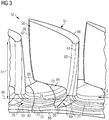
- FIG.3 is a view looking rearwardly at a number of blades 54 of an array of blades 52 the compressor-turbine 28 and in particular shows a contoured surface 55 of a platform 56 in accordance with the present invention.
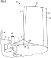
- Fig. 4 is a view looking circumferentially, along arrow B shown in Fig.3 , at the blade 54.
- Fig.4 shows a downstream end 64 of the vane platform 40 of one of the array of stator vanes 36 shown and described above.
- the blade 54 comprises an aerofoil 58 having a pressure side wall 59 and a suction side wall 60 that meet and define a leading edge 61 and a trailing edge 62.
- the aerofoil 58 is mounted to the blade platform 56, which is turn is mounted on a fixture that secures the blade to the rotor disc. This fixture is of a conventional configuration.
- the present invention relates to an aerofoil that comprises a leading edge foot 69 defining a first surface 70 and a platform 56 that is contoured and comprises a channel having a second surface 72.
- This arrangement could also be described as the having a forwardly extended platform; and the platform as defining the first and second surfaces 70, 72.
- a datum 49 is indicated by a circular line 49 in Figure 3 which is centred on the rotational axis 26 of the rotor and circumscribes each nominal junction between a leading edge 61 of the aerofoil 58 and the platform 56 around the rotational axis 26.
- a datum surface or plane is also indicated in Figure 4 by line 49P which can also represent part of the profile of the gas wash surface of a conventional platform.
- the datum surface or plane 49P is formed by rotation of the line 49P about the rotational axis 26.
- the datum surface is generally frusto-conical or it can be cylindrical in other cases.
- the datum surface 49P and datum line 49 can be an averaged plane or line of the radial heights of the first and second surfaces 70, 72 in accordance with the present invention.
- the cross-sectional area of the flow passage between aerofoils and radially facing endwalls (platform and casing) is the same as a conventional equivalent configuration.
- the cross-sectional area of the flow passage can be greater or smaller than a conventional equivalent configuration.
- the following description of the present invention refers to the datum line 49 and datum plane 49P.
- the first surface 70 is raised in radius compared to a conventional axisymmetric and circular rotor platform or raised relative to the datum line 49 or plane 49P.
- the second surface 72 is lower in radius compared to a conventional axisymmetric and circular rotor platform or radially lower relative to the datum line 49 or plane 49P.
- a platform leading edge 68 of the platform 56 extends axially forward of the aerofoil leading edge 61.
- the leading edge foot 69 starts at or close to the platform leading edge 68.
- An axial or seal gap 66 is formed between the downstream end 64 of the vane platform 40 and the platform leading edge 68.
- a seal nose 67 extends forwardly of the leading edge 68 to form an effective seal with corresponding seal features of the vane mountings 46 to form the seal 50.
- the first surface 70 has a maximum radial height relative to the datum line 49 and shown by a ridge line 71.
- the second surface 72 has a minimum radial height relative to the datum line 49 and shown by the channel line 73.
- the line 75 is a line of inflection between the two surfaces 70, 72.
- the first surface 70 is convex at the leading edge 68 of the platform and extends rearwardly and circumferentially next to the leading edge foot 69 region.
- the convex shape blends out downstream of the leading edge 61 of the aerofoil. In this exemplary embodiment the convex shape blends out immediately downstream of the leading edge foot 69. In other embodiments the convex shape can blend out at about the throat plane 80.
- the second surface 72 is concave. The first surface 70 and the second surface 72 are blended to provide a smooth gas wash surface.
- the aerofoil 54 has a radial span 51 defined here as from the datum 49 to the tip of or radially outermost part of the aerofoil.
- the aerofoil has a chord length which is defined along a line on the pressure side or suction side from the leading edge to the trailing edge.
- the aerofoils 54 are circumferentially spaced apart and such spacing is referred to as the pitch.
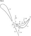
- Figure 5 is a schematic plan view of one nozzle guide vane 36 and one rotor blade 54 along with velocity vectors of the working gas flow at a particular design point.
- Working gas flow impinges on the nozzle guide vane 36 and is forced to follow the curvature of the vane such that as the gas flow exits the vane's trailing edge it has a velocity vector C2 comprising circumferential and axial velocity components.
- the rotor blade 54 is rotated by the impinging working gases in the direction of velocity arrow ⁇ b in a circumferential direction.
- the relative velocity of the gas flow onto the leading edge 61 of the rotor blade 54 is along the line V2.
- the leading edge foot 69 extends to the seal gap 66.
- the radial height is about the same as the conventional platform or datum surface 49.
- the leading edge foot 69 has a smooth transition where it blends into the leading edge 68 that forms part of the seal gap 66.
- the radial height of the junction where the ridge line 71 meets the leading edge 68 is approximately the same as the conventional platform leading edge design.
- the ridge line 71 is aligned with the relative velocity vector V 2 and meets the geometric leading edge 61 of the blade at a radial location or height which is 12.5% of the radial span 51 and relative to the datum 49.
- This radial height can be between and include 5% to 25% of the radial span 51 relative to the datum 49 to gain at least some of the benefits of the present invention, but preferably this radial height is between 10%-15% radial span 51 for most applications.
- the geometric leading edge 61 is the axially forward part of the aerofoil 54 and in this example is the geometric leading edge or forward most line along the radial extent of the aerofoil 54. It is also possible for the leading edge 61 to be defined as the aerodynamic leading edge, which is defined as the point at which gas flow separates between pressure side and suction side flows. The position of the aerodynamic leading edge can vary dependent on the operating condition of the engine.
- the geometric and aerodynamic leading edges are within a leading edge region 63 which extends from the geometric leading edge 61 rearwardly a distance of 5% of the aerofoil's chord length at a particular radial position.
- the leading edge foot 69 has its ridge line 71 meeting, at position 76 (in Fig.4 ), the aerodynamic leading edge 61 of the aerofoil 54 at a radial height of 12.5% of the radial span 51 of the aerofoil.
- the applicant believes the present invention is advantageous where the radial height of the foot at the intersection of the ridge 71 and leading edge 61 is between and includes 5% to 25% of the radial span 51. It is believed that the most effective range of radial heights of the foot at the intersection is between and includes 10% and 15% of the aerofoil's radial span 51.
- the leading edge foot 69 blends out towards the trailing edge 62 of the rotor blade 54 and smoothly transitions with the surface of the channel 74 on the platform.
- the blend out or the axial extent of the leading edge foot 69 on the pressure side 59 is between a mid-chord position 84 and the trailing edge 62. This blend out achieves a smooth transition to the airfoil pressure side 59 and the platform channel 74. In this exemplary embodiment of Figure 3 , the blend out occurs at a position 75% of the aerofoil chord length from the leading edge 61.
- the blend-out or axial extent of the leading edge foot 69 may be between and including 50% and 100% of the chord length from the leading edge 61.
- the leading edge foot 69 merges with the platform channel 74, described in more detail below, to form a smooth transition.
- the blend out on the suction side 60 can take place between the suction side crown 78 and the throat plane 80 as shown in Figs. 6A and 6B .
- the blend out or axial extent of the leading edge foot 69 occurs at approximately 50% of the suction surface chord length from the leading edge 61.
- the leading edge foot 69 may blend out between and including the suction side crown 78 and the throat plane 80.
- Figure 6A is a plan view, looking radially inwardly, of two circumferentially adjacent aerofoils 54. Scales of an aerofoil pitch 90, a throat plane 80 and an axial extent C ax are shown. The scales can be interpreted as percentages of these geometric parameters.
- the aerofoil pitch 90 is the circumferential distance from one aerofoil to another and as shown from the leading edge 61 of one aerofoil to the leading edge 61 of the adjacent.
- the throat plane 80 is the location of the minimum area of the gas passage defined by the aerofoils and any end wall, platform or casing depending on application to a blade or vane.
- the throat plane 80 is located from the suction side of one aerofoil (0%) to the pressure side of the adjacent blade near to the trailing edge (100%) and immediately before the rounded trailing edge profile begins.
- the axial extent C ax is measured from the leading edge 61 of the aerofoil (0%) and in an axially rearward direction, parallel to the engine axis 26, with 100% at the trailing edge 62.
- Figure 6B is a plan view, looking radially inwardly, of one aerofoil 54 and platform showing angles of the channel 74 and leading edge foot 69 relative to the axis 26.
- the ridge line 71 of the leading edge foot 69 is aligned with the oncoming main working gas flow 29 having relative velocity vector V 2 .
- the ridge line 71 is generally linear and parallel to the relative velocity vector V 2 .
- the ridge line 71 may be angled relative to the oncoming main working gas flow 29 and at different working condition the relative velocity vector V 2 may be different due to the different speeds ⁇ b of the rotor for example.
- the angle 92 of the ridge line 71 may be angled in the range 0 degrees to 45 degrees relative to the engine axis 26. In the case of a vane the angle 92 of the ridge line 71 may be angled in the range -45 degrees to 0 degrees relative to the engine axis 26.
- the ridge line 71 may be curvilinear as shown by the line 93.
- the upstream part of the curvilinear ridge line 93 can be angled to be aligned with the oncoming main working gas flow direction and assist in turning the flow onto the pressure side surface of the aerofoil.
- the channel 74 is formed by the platform surface or second surface 72. Rather than a cylindrical or conical platform surface of a conventional design as indicated by the datum line 49, the platform surface 72 is radially lowered towards a radially lowest line or minimum radial height line 73 as shown in Fig.3 , Fig.4 and Figs. 6A and 6B .
- a channel entry 82 is formed at the platform leading edge and which is in the rim-seal outlet region 50. The channel entry 82 extends to and partly forms the axial or seal gap 66.
- the minimum radial height line 73 is initially aligned with the direction of the egress seal leakage flow 31 from the seal gap 66 and extends up to a throat plane or area 80.
- the minimum radial height line 73 is initially angled within 30 degrees of the axis 26 in a plan view looking radially inwardly. As the seal leakage flow 31 travels along or over the platform surface 55 it tends to follow the curvature of the blade aerofoil through the gas passage.
- the throat plane 80 is defined by a minimum distance between the trailing edge 62 of one aerofoil to the suction surface of a neighbouring aerofoil.
- the channel 74 may curtail axially forward or axially rearward of the throat plane 80. However, in either case the resultant throat area may be affected and thus this should be considered in the design of the blade or vane array.
- the channel 74 extends to the throat plane 80, but can extend to within 10% of an axial extent, Cax, of the aerofoil from a throat area plane 80.
- the maximum channel depth or its radially lowest line 73 is approximately 10% of the blade's radial span 51 radially lower than datum line 49 or the conventional axisymmetric platform. It is believed that a maximum depth or radial lowering from nominal can be up to 20% of the radial span 51 of the aerofoil and a minimum of 2.5% to have a beneficial effect. One preferred or optimal range is between and including 5% - 10% of the radial span 51 of the aerofoil.
- This arrangement is advantageous in having the radially lowest part or the maximum depth of the channel 74 in the axial range between the leading edge 61 and the suction surface crown 78 because the flow field decelerates and hence increases the static pressure on the suction side to create a more favourable pressure gradient to reduce the cross passage secondary flow.
- the relative radial height of the channel 73/74 depends on the type of seal arrangement 67. For the example described here, this is a preferred configuration; however, the radial height of the channel can vary where other configurations of the rim seal 67 is used.
- the channel 73/74 is blended out near the throat plane 80. In other examples, the channel 73/74 may extend further downstream and beyond the throat plane 80 and towards the aerofoil trailing edge 62 or even the trailing edge of the platform 44.
- the radially lowest line 73 of the channel 74 starts circumferentially between the elongated leading edge foot 69 on the platform with a position biased towards the suction side 60.
- the exact location for any given geometry is determined by the peak egress flow position at the rim-seal outlet 50 and channel entry 82 and is relative to the rotor blade leading edge 61 in a circumferentially sense.
- the location of the radially lowest line 73 is normally between 20% - 60% of blade pitch as shown in Fig.6A and 6B from the suction side 60.
- the radially lowest line 73 is a distance approximately 20% of the blade throat pitch range at the throat plane 80. In other examples, the radially lowest line 73 is within range of a distances equivalent to 5% - 35% of the blade throat pitch range at the throat plane 80.
- the channel orientation at the blade platform upstream entry region 82 is mainly determined by the average egress flow direction and the projection of this on to the blade platform is normally approximately parallel to the machine axial direction 26 and may be within ⁇ 30° of the axis 26. Moving axially rearwards as the deepest channel path line 73 approaches the suction side of the aerofoil it follows the streamwise direction until it merges with the conventional axisymmetric platform before or at the throat plane 80.
- the aerofoil and platform configuration is equally applicable to a blade array or a vane array.
- the aerofoil and platform configuration may be applied to either or both the radially inner or radially outer gas passage surfaces.
- the aerofoil and platform configuration is advantageous because the main working gas flow and the seal leakage flow incur less viscous mixing in the passage owing to a reduced secondary flow and better control of discharging sealing flow; hence there is an increase in stage efficiency.
- a decrease in surface gas temperature of the platform has been identified.
- the seal leakage flow remains attached to the platform surface 55 further downstream thereby increasing cooling coverage. It is also found that there is a reduced likelihood of ingestion to the disc wheel space of hot working fluid by virtue of a more favourable external driving pressure due to the reduced leading edge loading of the blades and secondary flows.
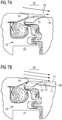
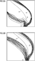
- FIGs 7A and 7B these circumferential views of the seal 50 and outlet regions of a conventional design and the present invention respectively show the seal leakage flow 31 egressing the outlet 66.
- the egressing leakage flow is forced radially outwardly and over the conventional platform shown by datum line 49.
- the egressing flow 31 mixes with the main working gas flow 29 around and immediately downstream of the outlet 66 causing turbulence and the hot working gas to impinge on the platform 45 and aerofoil surfaces.
- the egressing leakage flow 31 is forced into the channel 74 and along with the effect of the leading edge foot 69 on the main working gas flow, separates the two gas flows preventing or significantly reducing mixing.
- the reduced entry point of the main working gas flow 29 or streamline next to the channel at the platform entry region and into the platform channel indicates a reduced angle of the leakage flow 31 relative to the mainstream flow as it is pushed into this channel by the mainstream flow. This means that the egressing coolant flow 31 remains attached to the platform surface in the channel and it mixes less with the mainstream flow. This reduces aerodynamic losses associated with the two flows when they mix.
- the egressing coolant or leakage flow 31 enters the passage between aerofoils its temperature is lower than the conventional design which has a benefit for improved platform cooling.
- FIGs 8A and 8B show velocity streamlines of the main working gas flow 29 for the convention design and present invention respectively. These velocity streamlines are initiated in the endwall region or near to the surface of the platform.
- the conventional design causes horseshoe vortices 96 which are aerodynamically inefficient.
- the horseshoe vortices are significantly reduced and can be eliminated completely.
- the main working gas flow 29 the streamlines are significantly more linear and smoother. Thus this creates a more aerodynamically efficient condition improving overall engine efficiency.
- the cross passage secondary or leakage flow 31 from the pressure side 59 to the suction side 60 has also been significantly reduced by virtue of the leading edge foot 69 and channel 74.
- leading edge foot 69 and channel 74 features of the present invention leads to a reduction in blade front aerodynamic loading and hence a more favourable pressure gradient that reduces the cross passage flow of the main working gas. This further helps to reduce the secondary flow 31 and hence less secondary flow losses. The further reduction in cross-passage secondary flow also helps the egress coolant to stay on the platform surface much further downstream rather than being swept across the passage relatively early in the conventional design. This gives an improved benefit to blade platform cooling.
- Figures 9A and 9B are plan views of an aerofoil showing streamlines of a seal leakage gas flow for a convention design and the present invention respectively.
- the streamline arrows 98 have a significant circumferential velocity vector.
- the velocity vector arrows 100 have a lesser velocity vector in the circumferential direction.
- the streamlines are more in alignment with gas passage shape. Thus this reduction in cross-flow improves the efficiency of the gas flow and overall efficiency of the gas turbine engine.
Description
- This invention relates to a blade or vane arrangement and in particular, an aerofoil and platform configuration of a rotor blade or a stator vane, particularly but not exclusively, for a gas turbine engine.
- In a turbine engine, compressors and turbines typically have axially arranged and alternate sets or stages of rotor blades and stator vanes. The stator vanes are mounted to a casing and the rotor blades are mounted to rotor discs. The rotor blades and stator vanes each comprise aerofoils mounted on platforms and the surfaces of which define a working gas flow passage.
- The efficiency of the engine is strongly influenced by the shape and the configuration of the aerodynamic surfaces of the rotor blades and stator vanes. The behaviour of the main working gas flow through the compressor and turbine is highly complex and can vary dependent on the engine output, the input of secondary gas flows to the main working gas flow and locally throughout the gas flow passage.
- For turbines in particular, additional complexity in the working gas flow can arise from the temperature traverse of the working gas flow from the combustor and thermal characteristics of the turbine blades and stator vanes. Numerous attempts have been made to optimise certain aspects of blade and vane designs to improve stage efficiency and thermal management of the gas flow passage surfaces.
-
WO0061918A2 -
EP1074697 A2 discloses a method for inhibiting radial transfer of core gas flow away from a center radial region and toward the inner and outer radial boundaries of a core gas flow path. A flow directing structure includes an airfoil having a fillet which diverts the core gas flow away from the area where the airfoil abuts the end wall. Increasing the velocity of the core gas flow in the area where the leading edge of the airfoil abuts the wall impedes the formation of a pressure gradient along the surface of the airfoil that forces core gas from the center region of the core gas toward the wall. - In "Turbine Blade Aerodynamics", by Sumanta Acharya & Gazi Mahmood, Louisiana State University, CEBA 1419B, Mechanical Engineering Department, pages 363-390 there is disclosed a Leading Edge Fillet or leading edge contouring near the endwall. Fillets are placed at the junction of the leading edge and endwall. Two types of basic construction of fillet profiles can be identified: (i) profile with varying height from the blade surface to the endwall and (ii) profile of bulb with surface thickness at the outer periphery.
-
US2010/0158696A1 discloses a turbine blade including an airfoil and integral platform at the root thereof. The platform is contoured in elevation from a ridge to a trough, and is curved axially to complement the next adjacent curved platform. - However, none of these documents address the problems associated with from the interaction of the main working gas flow and secondary or leakage flow egressing immediately upstream of a set of rotor blades or stator vanes.
- One objective or advantage of the present invention is to improve the efficiency of a blade or vane arrangement. Another objective is to reduce or eliminate aerodynamic losses incurred from the interaction of the main working gas flow and secondary or leakage flow. Another objective is to reduce or eliminate horseshoe vortices formed at or near the leading edge of an aerofoil. Another objective is to improve the working gas flow streamlines so they are significantly more linear and smoother. Another objective is to create a more aerodynamically efficient aerofoil and platform arrangement for improving overall engine efficiency. Another objective is to reduce or eliminate cross passage secondary or leakage flow particularly from the pressure side to the suction side.
- Another objective or advantage of the present invention is a reduction in blade front aerodynamic loading and a more favourable pressure gradient that reduces the cross passage flow of the main working gas. Yet another advantage to reducing cross-passage secondary flow is that coolant remains attached to the platform surface much further downstream rather than being swept across the passage relatively early in a conventional design. This gives an improved benefit to blade platform cooling and a reduction in the amount of heat put into the aerofoil.
- For these and other objectives and advantages there is provided a blade or vane arrangement for a gas turbine engine. The arrangement having an array of aerofoils mounted to respective platforms about an axis and defining a passage through which a working gas flow passes. The arrangement has a datum and the aerofoil has a radial span. Each aerofoil has pressure side, a suction side, a leading edge region and a leading edge foot extending from the leading edge region, the leading edge foot has a ridge line. The platform defines a channel and a platform leading edge, the channel has a minimum radial height line, and the platform leading edge partly defines an outlet through which a secondary flow passes. The ridge line is aligned generally in the direction of the working gas flow and the minimum radial height line is aligned generally in the direction of the secondary flow.
- The leading edge foot and the channel may have gas washed surfaces that are smoothly blended to one another.
- The leading edge foot and the channel may extend axially forward of the leading edge to define part of the secondary flow outlet.
- The leading edge foot may extend axially forward of the leading edge region to the platform leading edge. The leading edge foot may extend axially forward of the leading edge region to within 10% chord length of aerofoil to the platform leading edge.
- The leading edge foot may meet the leading edge region at a radial height above the datum in the range 5% to 25% of the radial span.
- The radially lowest line may be at a radial height below the datum in the range 2.5% and 20% of the radial span. The radially lowest line may be at a radial height below the datum in the range 2.5% and 20% of the radial span at the maximum depth of the channel.
- The deepest or radially innermost point of the radially lowest line may be approximately at the axial position to the leading edge region.
- The deepest or radially innermost point of the line may be between the leading edge region and the crown on the suction side. The deepest or radially innermost point of the line may be at the leading edge region. The deepest or radially innermost point of the line may be at the crown on the suction side.
- The aerofoil has a leading edge and the leading edge region may be defined up to and including 5% of the chord length of the aerofoil from the leading edge. The leading edge region may be defined up to and including 10% of the chord length of the aerofoil from the leading edge.
- The leading edge may be any one of a geometric leading edge or an aerodynamic leading edge. The ridge line may meet the geometric or aerodynamic leading edge of the aerofoil.
- The ridge line may be linear or curvilinear or may be a combination of linear and curved or other arcuate form. The form may be relative to any one or more of the circumferential, radial or axial axes. The ridge line may be angled with respect to the axis. The angle with respect to the axis may be when viewed looking radially inwardly. The angle may have a circumferential component. The ridge line may be angled in the
range 0 degrees and 45 degrees. The angle may be clockwise or anticlockwise when viewed along the axis of the rotor or engine. - The radially lowest channel path line may be initially angled within 30 degrees of the axis. The radially lowest channel path line may have an upstream part or entry part which is angled within 30 degrees of the axis when viewed radially inwardly. The radially lowest channel path line may be initially angled within approximately parallel to the axis. The angle with respect to the axis may be when viewed looking radially inwardly.
- The channel may extend to within and including 10% of an axial extent of the aerofoil from and including a throat area plane. The channel may extend axially forward of or axially rearward of the throat area plane. The channel may extend axially to a trailing edge of the platform. The channel may extend axially to a trailing edge of the aerofoil. The channel may extend axially to between the trailing edge of the platform and the trailing edge of the aerofoil.
- The circumferential location of the radially lowest line may be between and including 20% to 60% of an aerofoil pitch from the suction side. The circumferential location of the radially lowest line may be between and including 20% to 60% of an aerofoil pitch from the suction side at channel entry.
- At least a portion of the radially lowest line may be located between and includes 5% - 35% of the pitch from the suction side at or near the throat plane. At least a portion of the radially lowest line may be located between and includes 5% - 35% of the throat pitch.
- The leading edge foot may blend out a distance between and including 50% and 100% of an aerofoil chord length from the leading edge region on the pressure side.
- The leading edge foot may blend out between and including a suction side crown and the throat plane on the suction side. The suction side crown is a circumferentially forward most point on the aerofoil. The throat plane on the suction side is the position where the throat plane intersects the surface of the suction side wall.
- At the leading edge of the platform the ridge line may be aligned generally in the direction of the working gas flow. At the leading edge of the platform the minimum radial height line may be aligned generally in the direction of the secondary flow. At the leading edge of the platform the ridge line may be aligned generally in the direction of the working gas flow and the minimum radial height line may be aligned generally in the direction of the secondary flow.
- The blade or vane arrangement is one of an annular array of blades or vane. A rotor assembly may include a disc supporting an annular array of blades. A stator assembly may include a radially inner or outer casing supporting an annular array of stator vanes. A compressor or a turbine may include any one or both the blade or vane arrangement.
- The blade or vane arrangement may be of a gas turbine engine for aerospace, marine or industrial application.
- The above mentioned attributes and other features and advantages of this invention and the manner of attaining them will become more apparent and the invention itself will be better understood by reference to the following description of embodiments of the invention taken in conjunction with the accompanying drawings, wherein;
-
Figure 1 shows part of a turbine engine in a sectional view and in which the present invention is incorporated, -
Figure 2 shows an enlarged view of region A inFig.1 and is part of a known compressor-turbine, -
Figure 3 is a view looking rearwardly at a number of blades of an array of blades of a compressor-turbine and in particular shows a contoured surface of a platform including a channel and leading edge foot of an aerofoil extending from its leading edge in accordance with the present invention, -
Figure 4 is a view looking circumferentially, along arrow B shown inFigure 3 , at theblade 54. In additionFigure 4 shows a downstream end of a vane platform of one of an array of stator vanes, -
Figure 5 is a schematic plan view, looking radially inwardly, of one nozzle guide vane and one rotor blade and relative rotational speed along with velocity vectors of the working gas flow at a particular design point, -
Figure 6A is a schematic plan view, looking radially inwardly, of two aerofoils showing relative scales of an aerofoil pitch, a throat plane and an axial aerofoil chord Cax, -
Figure 6B is a schematic plan view, looking radially inwardly, of one aerofoil and platform and showing angles of the channel and leading edge foot, -
Figures 7A and 7B are circumferential views of a seal and outlet region of a conventional design and the present invention respectively and show a seal leakage flow egressing the outlet, -
Figures 8A and 8B are plan views of an aerofoil showing streamlines of the main working gas flow for a convention design and the present invention respectively, and -
Figures 9A and 9B are plan views of an aerofoil showing streamlines of a seal leakage gas flow for a convention design and the present invention respectively. -
Figure 1 is a schematic illustration of a general arrangement of aturbine engine 10 having aninlet 12, acompressor 14, acombustor system 16, aturbine system 18, anexhaust duct 20 and a twin-shaft arrangement turbine engine 10 is generally arranged about anaxis 26 which for rotating components is their rotational axis. Thearrangements combustion system 16 comprises an annular array ofcombustor units 17, only one of which is shown. Theturbine system 18 includes a high-pressure turbine 28 or compressor-turbine which is drivingly connected to thecompressor 14 by afirst shaft 22 of the twin-shaft arrangement. Theturbine system 18 also includes a low-pressure turbine 30 drivingly connected to a load (not shown) via asecond shaft 24 of the twin-shaft arrangement. - The terms radial, circumferential and axial are with respect to the
axis 26. The terms upstream and downstream are with respect to the general direction of gas flow through the engine and as seen inFigure 1 is generally from left to right. - The
compressor 14 comprises an axial series of stator vanes and rotor blades mounted in a conventional manner. The stator or compressor vanes may be fixed or have variable geometry to improve the airflow onto the downstream rotor or compressor blades. Eachturbine - In
operation air 32 is drawn into theengine 10 through theinlet 12 and into thecompressor 14 where the successive stages of vanes and blades compress the air before delivering the compressed air into thecombustion system 16. In the combustor of thecombustion system 16 the mixture of compressed air and fuel is ignited. The resultant hot working gas flow is directed into and drives the high-pressure turbine 28 which in turn drives thecompressor 14 via thefirst shaft 22. After passing through the high-pressure turbine 28, the hot working gas flow is directed into the low-pressure turbine 30 which drives the load via thesecond shaft 24. - The low-
pressure turbine 30 can also be referred to as a power turbine and thesecond shaft 24 can also be referred to as a power shaft. The load is typically an electrical machine for generating electricity or a mechanical machine such as a pump or a process compressor. Other known loads may be driven via the low-pressure turbine. The fuel may be in gaseous or liquid form. - The
turbine engine 10 shown and described with reference tofigure 1 is just one example of a number of turbine engines in which this invention can be incorporated. Such engines include single, double and triple shaft engines applied in marine, industrial and aerospace sectors. This invention may also be applied to steam turbines. Indeed the configuration of the present shaft arrangement can have utility for shafts found in other situation such as ship propeller shafts and land transport shafts. -
Figure 2 is an enlarged view of region A inFig.1 and is part of a known compressor-turbine 28. The compressor-turbine 28 comprises, in working-gas flow series shown byarrow 29, an annular array ofstator vanes 36 and an annular array ofrotor blades 38. Further annular arrays of stator vanes and rotor blades are located downstream. - The annular array of
stator vanes 36 is provided to impart a swirl or circumferential vector to the working gas flow from the combustor to favourably direct the working gas onto therotor blades 38 to drive therotor disc 30 and in turn thecompressor 14 via theshaft 22. - Each
vane 36 of the annular array ofstator vanes 36 includes anaerofoil 37 mounted between a radiallyinner vane platform 40 and a radiallyouter vane platform 42. The annular array ofstator vanes 36 are secured in a conventional manner referred to here asvane mountings 46. Eachrotor blade 38 of its annular array includes anaerofoil 39 mounted on ablade platform 44 and rotating within acasing 41 that surrounds the rotor assembly. - The
aerofoils - This annular array of conventional
rotor blade platforms 44 form a conical and axisymmetric gas-wash surface 45. A conventional small fillet is provided between theplatform 44 and theaerofoil 39 to give a smooth transition of their surfaces to reduce stresses. - The platforms and casing form a working
gas passage 43 through theturbine 28 and are gas-washed surfaces. Aseal 50 is defined by the annular array ofvanes 36 / vane mounting 46 and therotor assembly - Radially inwardly of the
vane platform 40 andblade platform 44 and generally axially between thevane mountings 46 and the blade /disc assembly disc wheel space 48. Cooling air is used in a conventional manner to cool thevane array 36, therotor blades 38 and thedisc 30. Some of the cooling air enters thedisc wheel space 48. Additional cooling air is also applied at the wheel-space 48 to prevent hot gas ingestion from entering the wheel-space. This cooling air with the ingested hot fluid discharges as shown byarrow 31 through theseal 50 and enters the workinggas passage 43. Theseal 50 and the egressing cooling flow is desirable because a positive pressure of the coolant in thedisc wheel space 48 normally prevents hot workinggases 29 entering theseal 50 and into thedisc wheel space 48. - During operation, this conventional configuration incurs a strong cross-flow of working gases across the aerofoil passage in the end wall platform region. This is caused by a high pressure gradient from the pressure side wall to the suction side wall. Furthermore, the gas flow stagnates in front of the leading edge region of the aerofoil at the junction between leading edge and platform causes strong horse-shoe vortices to form. Both the cross-flow and the horse-shoe vortices lead to significant secondary flow or aerodynamic losses.
- Thus one problem of the conventional arrangement described above is the aerodynamic interaction of the working
gas flow 29 with the dischargingsealing flow 31 of coolant from disc wheel-space 48. This interaction leads to aerodynamic losses, increased temperatures of the surfaces in the gas passage and in some operational conditions of the engine ingestion of the hot working gases into theside wheel space 48. - Referring now to
Figures 3 and4 which depict an exemplary embodiment of the present invention.Fig.3 is a view looking rearwardly at a number ofblades 54 of an array ofblades 52 the compressor-turbine 28 and in particular shows acontoured surface 55 of aplatform 56 in accordance with the present invention.Fig. 4 is a view looking circumferentially, along arrow B shown inFig.3 , at theblade 54. In addition toFig.3 ,Fig.4 shows adownstream end 64 of thevane platform 40 of one of the array ofstator vanes 36 shown and described above. - The
blade 54 comprises anaerofoil 58 having apressure side wall 59 and asuction side wall 60 that meet and define aleading edge 61 and a trailingedge 62. Theaerofoil 58 is mounted to theblade platform 56, which is turn is mounted on a fixture that secures the blade to the rotor disc. This fixture is of a conventional configuration. - The present invention relates to an aerofoil that comprises a
leading edge foot 69 defining afirst surface 70 and aplatform 56 that is contoured and comprises a channel having asecond surface 72. This arrangement could also be described as the having a forwardly extended platform; and the platform as defining the first andsecond surfaces - A
datum 49 is indicated by acircular line 49 inFigure 3 which is centred on therotational axis 26 of the rotor and circumscribes each nominal junction between aleading edge 61 of theaerofoil 58 and theplatform 56 around therotational axis 26. A datum surface or plane is also indicated inFigure 4 byline 49P which can also represent part of the profile of the gas wash surface of a conventional platform. The datum surface orplane 49P is formed by rotation of theline 49P about therotational axis 26. Here the datum surface is generally frusto-conical or it can be cylindrical in other cases. Thedatum surface 49P anddatum line 49 can be an averaged plane or line of the radial heights of the first andsecond surfaces datum line 49 anddatum plane 49P. - The
first surface 70 is raised in radius compared to a conventional axisymmetric and circular rotor platform or raised relative to thedatum line 49 orplane 49P. Thesecond surface 72 is lower in radius compared to a conventional axisymmetric and circular rotor platform or radially lower relative to thedatum line 49 orplane 49P. - A
platform leading edge 68 of theplatform 56 extends axially forward of theaerofoil leading edge 61. Theleading edge foot 69 starts at or close to theplatform leading edge 68. An axial orseal gap 66 is formed between thedownstream end 64 of thevane platform 40 and theplatform leading edge 68. A seal nose 67 extends forwardly of the leadingedge 68 to form an effective seal with corresponding seal features of thevane mountings 46 to form theseal 50. - The
first surface 70 has a maximum radial height relative to thedatum line 49 and shown by aridge line 71. Thesecond surface 72 has a minimum radial height relative to thedatum line 49 and shown by thechannel line 73. Theline 75 is a line of inflection between the twosurfaces first surface 70 is convex at theleading edge 68 of the platform and extends rearwardly and circumferentially next to theleading edge foot 69 region. The convex shape blends out downstream of the leadingedge 61 of the aerofoil. In this exemplary embodiment the convex shape blends out immediately downstream of theleading edge foot 69. In other embodiments the convex shape can blend out at about thethroat plane 80. Thesecond surface 72 is concave. Thefirst surface 70 and thesecond surface 72 are blended to provide a smooth gas wash surface. - The
aerofoil 54 has aradial span 51 defined here as from thedatum 49 to the tip of or radially outermost part of the aerofoil. The aerofoil has a chord length which is defined along a line on the pressure side or suction side from the leading edge to the trailing edge. Theaerofoils 54 are circumferentially spaced apart and such spacing is referred to as the pitch. -
Figure 5 is a schematic plan view of onenozzle guide vane 36 and onerotor blade 54 along with velocity vectors of the working gas flow at a particular design point. Working gas flow impinges on thenozzle guide vane 36 and is forced to follow the curvature of the vane such that as the gas flow exits the vane's trailing edge it has a velocity vector C2 comprising circumferential and axial velocity components. Therotor blade 54 is rotated by the impinging working gases in the direction of velocity arrow Ωb in a circumferential direction. Thus the relative velocity of the gas flow onto the leadingedge 61 of therotor blade 54 is along the line V2. - In this exemplary embodiment, the leading
edge foot 69 extends to theseal gap 66. At theseal gap 66, the radial height is about the same as the conventional platform ordatum surface 49. Theleading edge foot 69 has a smooth transition where it blends into the leadingedge 68 that forms part of theseal gap 66. The radial height of the junction where theridge line 71 meets the leadingedge 68 is approximately the same as the conventional platform leading edge design. At the intersection with the leading edge of the platform, theridge line 71 is aligned with the relative velocity vector V2 and meets the geometric leadingedge 61 of the blade at a radial location or height which is 12.5% of theradial span 51 and relative to thedatum 49. This radial height can be between and include 5% to 25% of theradial span 51 relative to thedatum 49 to gain at least some of the benefits of the present invention, but preferably this radial height is between 10%-15% radial span 51 for most applications. - The geometric
leading edge 61 is the axially forward part of theaerofoil 54 and in this example is the geometric leading edge or forward most line along the radial extent of theaerofoil 54. It is also possible for theleading edge 61 to be defined as the aerodynamic leading edge, which is defined as the point at which gas flow separates between pressure side and suction side flows. The position of the aerodynamic leading edge can vary dependent on the operating condition of the engine. The geometric and aerodynamic leading edges are within aleading edge region 63 which extends from the geometric leadingedge 61 rearwardly a distance of 5% of the aerofoil's chord length at a particular radial position. - The
leading edge foot 69 has itsridge line 71 meeting, at position 76 (inFig.4 ), the aerodynamic leadingedge 61 of theaerofoil 54 at a radial height of 12.5% of theradial span 51 of the aerofoil. The applicant believes the present invention is advantageous where the radial height of the foot at the intersection of theridge 71 and leadingedge 61 is between and includes 5% to 25% of theradial span 51. It is believed that the most effective range of radial heights of the foot at the intersection is between and includes 10% and 15% of the aerofoil'sradial span 51. - On the
pressure side 59 of the aerofoil, the leadingedge foot 69 blends out towards the trailingedge 62 of therotor blade 54 and smoothly transitions with the surface of thechannel 74 on the platform. The blend out or the axial extent of theleading edge foot 69 on thepressure side 59 is between amid-chord position 84 and the trailingedge 62. This blend out achieves a smooth transition to theairfoil pressure side 59 and theplatform channel 74. In this exemplary embodiment ofFigure 3 , the blend out occurs at aposition 75% of the aerofoil chord length from the leadingedge 61. The blend-out or axial extent of theleading edge foot 69 may be between and including 50% and 100% of the chord length from the leadingedge 61. - On the
suction side 60 of the aerofoil, the leadingedge foot 69 merges with theplatform channel 74, described in more detail below, to form a smooth transition. The blend out on thesuction side 60 can take place between thesuction side crown 78 and thethroat plane 80 as shown inFigs. 6A and 6B . In this example the blend out or axial extent of theleading edge foot 69 occurs at approximately 50% of the suction surface chord length from the leadingedge 61. In other examples theleading edge foot 69 may blend out between and including thesuction side crown 78 and thethroat plane 80. -
Figure 6A is a plan view, looking radially inwardly, of two circumferentiallyadjacent aerofoils 54. Scales of anaerofoil pitch 90, athroat plane 80 and an axial extent Cax are shown. The scales can be interpreted as percentages of these geometric parameters. Theaerofoil pitch 90 is the circumferential distance from one aerofoil to another and as shown from the leadingedge 61 of one aerofoil to the leadingedge 61 of the adjacent. Thethroat plane 80 is the location of the minimum area of the gas passage defined by the aerofoils and any end wall, platform or casing depending on application to a blade or vane. In this example, thethroat plane 80 is located from the suction side of one aerofoil (0%) to the pressure side of the adjacent blade near to the trailing edge (100%) and immediately before the rounded trailing edge profile begins. The axial extent Cax is measured from the leadingedge 61 of the aerofoil (0%) and in an axially rearward direction, parallel to theengine axis 26, with 100% at the trailingedge 62. -
Figure 6B is a plan view, looking radially inwardly, of oneaerofoil 54 and platform showing angles of thechannel 74 andleading edge foot 69 relative to theaxis 26. Theridge line 71 of theleading edge foot 69 is aligned with the oncoming main workinggas flow 29 having relative velocity vector V2. In this example theridge line 71 is generally linear and parallel to the relative velocity vector V2. However, in other examples theridge line 71 may be angled relative to the oncoming main workinggas flow 29 and at different working condition the relative velocity vector V2 may be different due to the different speeds Ωb of the rotor for example. Theangle 92 of theridge line 71 may be angled in therange 0 degrees to 45 degrees relative to theengine axis 26. In the case of a vane theangle 92 of theridge line 71 may be angled in the range -45 degrees to 0 degrees relative to theengine axis 26. - Furthermore, the
ridge line 71 may be curvilinear as shown by theline 93. The upstream part of thecurvilinear ridge line 93 can be angled to be aligned with the oncoming main working gas flow direction and assist in turning the flow onto the pressure side surface of the aerofoil. - The
channel 74 is formed by the platform surface orsecond surface 72. Rather than a cylindrical or conical platform surface of a conventional design as indicated by thedatum line 49, theplatform surface 72 is radially lowered towards a radially lowest line or minimumradial height line 73 as shown inFig.3 ,Fig.4 andFigs. 6A and 6B . Achannel entry 82 is formed at the platform leading edge and which is in the rim-seal outlet region 50. Thechannel entry 82 extends to and partly forms the axial orseal gap 66. - The minimum
radial height line 73 is initially aligned with the direction of the egress seal leakage flow 31 from theseal gap 66 and extends up to a throat plane orarea 80. The minimumradial height line 73 is initially angled within 30 degrees of theaxis 26 in a plan view looking radially inwardly. As theseal leakage flow 31 travels along or over theplatform surface 55 it tends to follow the curvature of the blade aerofoil through the gas passage. - The
throat plane 80 is defined by a minimum distance between the trailingedge 62 of one aerofoil to the suction surface of a neighbouring aerofoil. Thechannel 74 may curtail axially forward or axially rearward of thethroat plane 80. However, in either case the resultant throat area may be affected and thus this should be considered in the design of the blade or vane array. In this exemplary embodiment, thechannel 74 extends to thethroat plane 80, but can extend to within 10% of an axial extent, Cax, of the aerofoil from athroat area plane 80. - The maximum channel depth or its radially
lowest line 73 is approximately 10% of the blade'sradial span 51 radially lower thandatum line 49 or the conventional axisymmetric platform. It is believed that a maximum depth or radial lowering from nominal can be up to 20% of theradial span 51 of the aerofoil and a minimum of 2.5% to have a beneficial effect. One preferred or optimal range is between and including 5% - 10% of theradial span 51 of the aerofoil. The deepest point of theline 73 relative to thedatum platform 49 or the maximum depth ofchannel 74 is where Cax = 0, i.e. at theleading edge 61 axial location of the blade or shortly downstream of this point up to thesuction surface crown 78 axial position. This arrangement is advantageous in having the radially lowest part or the maximum depth of thechannel 74 in the axial range between theleading edge 61 and thesuction surface crown 78 because the flow field decelerates and hence increases the static pressure on the suction side to create a more favourable pressure gradient to reduce the cross passage secondary flow. - At the
channel entry 82, at theplatform leading edge 68, the relative radial height of thechannel 73/74 depends on the type of seal arrangement 67. For the example described here, this is a preferred configuration; however, the radial height of the channel can vary where other configurations of the rim seal 67 is used. Thechannel 73/74 is blended out near thethroat plane 80. In other examples, thechannel 73/74 may extend further downstream and beyond thethroat plane 80 and towards theaerofoil trailing edge 62 or even the trailing edge of theplatform 44. - The radially
lowest line 73 of thechannel 74 starts circumferentially between the elongatedleading edge foot 69 on the platform with a position biased towards thesuction side 60. The exact location for any given geometry is determined by the peak egress flow position at the rim-seal outlet 50 andchannel entry 82 and is relative to the rotorblade leading edge 61 in a circumferentially sense. Preferably, the location of the radiallylowest line 73 is normally between 20% - 60% of blade pitch as shown inFig.6A and 6B from thesuction side 60. Within blade passage the radiallylowest line 73 is a distance approximately 20% of the blade throat pitch range at thethroat plane 80. In other examples, the radiallylowest line 73 is within range of a distances equivalent to 5% - 35% of the blade throat pitch range at thethroat plane 80. - The channel orientation at the blade platform
upstream entry region 82 is mainly determined by the average egress flow direction and the projection of this on to the blade platform is normally approximately parallel to the machineaxial direction 26 and may be within ±30° of theaxis 26. Moving axially rearwards as the deepest channel path line 73 approaches the suction side of the aerofoil it follows the streamwise direction until it merges with the conventional axisymmetric platform before or at thethroat plane 80. - The aerofoil and platform configuration is equally applicable to a blade array or a vane array. For a vane array the aerofoil and platform configuration may be applied to either or both the radially inner or radially outer gas passage surfaces.
- The aerofoil and platform configuration is advantageous because the main working gas flow and the seal leakage flow incur less viscous mixing in the passage owing to a reduced secondary flow and better control of discharging sealing flow; hence there is an increase in stage efficiency. In addition, a decrease in surface gas temperature of the platform has been identified. Further, the seal leakage flow remains attached to the
platform surface 55 further downstream thereby increasing cooling coverage. It is also found that there is a reduced likelihood of ingestion to the disc wheel space of hot working fluid by virtue of a more favourable external driving pressure due to the reduced leading edge loading of the blades and secondary flows. - Referring to
Figures 7A and 7B , these circumferential views of theseal 50 and outlet regions of a conventional design and the present invention respectively show theseal leakage flow 31 egressing theoutlet 66. InFigure 7A , the egressing leakage flow is forced radially outwardly and over the conventional platform shown bydatum line 49. In this case the egressingflow 31 mixes with the main workinggas flow 29 around and immediately downstream of theoutlet 66 causing turbulence and the hot working gas to impinge on theplatform 45 and aerofoil surfaces. For the present invention as shown inFigure 7B , theegressing leakage flow 31 is forced into thechannel 74 and along with the effect of theleading edge foot 69 on the main working gas flow, separates the two gas flows preventing or significantly reducing mixing. - The reduced entry point of the main working
gas flow 29 or streamline next to the channel at the platform entry region and into the platform channel indicates a reduced angle of theleakage flow 31 relative to the mainstream flow as it is pushed into this channel by the mainstream flow. This means that the egressingcoolant flow 31 remains attached to the platform surface in the channel and it mixes less with the mainstream flow. This reduces aerodynamic losses associated with the two flows when they mix. When the egressing coolant orleakage flow 31 enters the passage between aerofoils its temperature is lower than the conventional design which has a benefit for improved platform cooling. - A further advantage of the present invention can be seen in
Figures 8A and 8B which show velocity streamlines of the main workinggas flow 29 for the convention design and present invention respectively. These velocity streamlines are initiated in the endwall region or near to the surface of the platform. InFigure 8A , the conventional design causeshorseshoe vortices 96 which are aerodynamically inefficient. For the present invention shown inFigure 8B , the horseshoe vortices are significantly reduced and can be eliminated completely. As can be seen the main workinggas flow 29 the streamlines are significantly more linear and smoother. Thus this creates a more aerodynamically efficient condition improving overall engine efficiency. Furthermore, the cross passage secondary or leakage flow 31 from thepressure side 59 to thesuction side 60 has also been significantly reduced by virtue of theleading edge foot 69 andchannel 74. - The
leading edge foot 69 andchannel 74 features of the present invention leads to a reduction in blade front aerodynamic loading and hence a more favourable pressure gradient that reduces the cross passage flow of the main working gas. This further helps to reduce thesecondary flow 31 and hence less secondary flow losses. The further reduction in cross-passage secondary flow also helps the egress coolant to stay on the platform surface much further downstream rather than being swept across the passage relatively early in the conventional design. This gives an improved benefit to blade platform cooling. -
Figures 9A and 9B are plan views of an aerofoil showing streamlines of a seal leakage gas flow for a convention design and the present invention respectively. For the convention design inFigure 9A , there is a strong cross passage flow shown byarrows 98. In other words, thestreamline arrows 98 have a significant circumferential velocity vector. However, inFigure 9B , in the same location thevelocity vector arrows 100 have a lesser velocity vector in the circumferential direction. For the present invention, the streamlines are more in alignment with gas passage shape. Thus this reduction in cross-flow improves the efficiency of the gas flow and overall efficiency of the gas turbine engine. - While the invention has been illustrated and described in detail for a preferred embodiment the invention is not limited to these disclosed examples and other variations can be deducted by those skilled in the art in practicing the claimed invention.
Claims (17)
- A blade or vane arrangement for a gas turbine engine (10), the arrangement having an array of aerofoils mounted to respective platforms about an axis (26) and defining a passage (43) through which a working gas flow (29) passes,
the arrangement has a datum (49, 49P) and the aerofoil has a radial span (51),
each aerofoil has pressure side (59), a suction side (60), a leading edge region (63) and a leading edge foot (69) extending from the leading edge region (63), the leading edge foot (69) has a ridge line (71),
the platform (56) defines a channel (74) and a platform leading edge (68), the channel (74) has a minimum radial height line (73), and the platform leading edge (68) partly defines an outlet (66) through which a secondary flow (31) passes,
characterised in that the ridge line (71) is aligned generally in the direction of the working gas flow (29) and the minimum radial height line (73) is aligned generally in the direction of the secondary flow (31),
wherein the ridge line (71) is linear or curvilinear (93) and is angled with respect to the axis (26) in the range 0 degrees and 45 degrees. - The blade or vane arrangement as claimed in claim 1 wherein the leading edge foot (69) and the channel (74) have gas washed surfaces that are smoothly blended to one another.
- The blade or vane arrangement as claimed in any one of claims 1-2 wherein the leading edge foot (69) and the channel (74) extend axially forward of the leading edge (61) the define part of the secondary flow outlet (66).
- The blade or vane arrangement as claimed in any one of claims 1-3 wherein the leading edge foot (69) extends axially forward of the leading edge region (63) to the platform leading edge (68).
- The blade or vane arrangement as claimed in any one of claims 1-4 wherein the leading edge foot (69) meets the leading edge region (63) at a radial height above the datum (49, 49P) in the range 5% to 25% of the radial span (51).
- The blade or vane arrangement as claimed in any one of claims 1-5 wherein the radially lowest line (73) is at a radial height below the datum (49, 49P) in the range 2.5% and 20% of the radial span (51) at a maximum depth of the channel (74).
- The blade or vane arrangement as claimed in any one of claims 1-6 wherein a deepest or radially innermost point of the line (73) is approximately at the axial position of the leading edge region (63).
- The blade or vane arrangement as claimed in any one of claims 1-6 wherein a deepest or radially innermost point of the line (73) is between the leading edge region (63) and the crown on the suction side (78).
- The blade or vane arrangement as claimed in any one of claims 1-8 wherein the aerofoil has a leading edge (61) and the leading edge region (63) is defined up to and including 5% of the chord length of the aerofoil from the leading edge (61).
- The blade or vane arrangement as claimed in any one of claims 1-9 wherein the aerofoil has a leading edge (61) which is any one of the geometric or aerodynamic leading edge and the ridge line (71) meets the leading edge (61).
- The blade or vane arrangement as claimed in any one of claims 1-10 wherein the radially lowest channel path line (73) is initially angled within 30 degrees of the axis (26).
- The blade or vane arrangement as claimed in any one of claims 1-11 wherein the channel (74) extends to within 10% of an axial extent of the aerofoil from and including a throat area plane (80).
- The blade or vane arrangement as claimed in any one of claims 1-12 wherein the circumferential location of the radially lowest line (73) is between and includes 20% to 60% of an aerofoil pitch (90) from the suction side (60) at channel entry (82).
- The blade or vane arrangement as claimed in any one of claims 1-13 wherein at least a portion of the radially lowest line (73) is located between and includes 5% - 35% of the pitch (90) from the suction side (60) at or near the throat plane (80).
- The blade or vane arrangement as claimed in any one of claims 1-14 wherein the leading edge foot (69) blends out a distance between and including 50% and 100% of an aerofoil chord length from the leading edge region (63) on the pressure side (59).
- The blade or vane arrangement as claimed in any one of claims 1-15 wherein the leading edge foot (69) blends out between and including the suction side crown and the throat plane (80) on the suction side (60).
- The blade or vane arrangement as claimed in any one of claims 1-16 wherein at the leading edge (68) of the platform the ridge line (71) is aligned generally in the direction of the working gas flow (29) and the minimum radial height line (73) is aligned generally in the direction of the secondary flow (31).
Applications Claiming Priority (2)
| Application Number | Priority Date | Filing Date | Title |
|---|---|---|---|
| GBGB1315078.4A GB201315078D0 (en) | 2013-08-23 | 2013-08-23 | Blade or vane arrangement for a gas turbine engine |
| PCT/EP2014/066259 WO2015024741A1 (en) | 2013-08-23 | 2014-07-29 | Blade or vane arrangement for a gas turbine engine |
Publications (2)
| Publication Number | Publication Date |
|---|---|
| EP3036403A1 EP3036403A1 (en) | 2016-06-29 |
| EP3036403B1 true EP3036403B1 (en) | 2017-12-13 |
Family
ID=49302106
Family Applications (1)
| Application Number | Title | Priority Date | Filing Date |
|---|---|---|---|
| EP14753026.5A Active EP3036403B1 (en) | 2013-08-23 | 2014-07-29 | Blade or vane arrangement for a gas turbine engine |
Country Status (6)
| Country | Link |
|---|---|
| US (1) | US10294796B2 (en) |
| EP (1) | EP3036403B1 (en) |
| CN (1) | CN105473823B (en) |
| CA (1) | CA2920277C (en) |
| GB (1) | GB201315078D0 (en) |
| WO (1) | WO2015024741A1 (en) |
Families Citing this family (10)
| Publication number | Priority date | Publication date | Assignee | Title |
|---|---|---|---|---|
| EP3115693B1 (en) * | 2015-07-10 | 2021-09-01 | Ansaldo Energia Switzerland AG | Sequential combustor and method for operating the same |
| DE102016211315A1 (en) * | 2016-06-23 | 2017-12-28 | MTU Aero Engines AG | Runner or vane with raised areas |
| GB201719538D0 (en) * | 2017-11-24 | 2018-01-10 | Rolls Royce Plc | Gas turbine engine |
| US11118466B2 (en) * | 2018-10-19 | 2021-09-14 | Pratt & Whiiney Canada Corp. | Compressor stator with leading edge fillet |
| JP7406920B2 (en) | 2019-03-20 | 2023-12-28 | 三菱重工業株式会社 | Turbine blades and gas turbines |
| US10822987B1 (en) | 2019-04-16 | 2020-11-03 | Pratt & Whitney Canada Corp. | Turbine stator outer shroud cooling fins |
| FR3098244B1 (en) * | 2019-07-04 | 2021-09-10 | Safran Aircraft Engines | TURBOMACHINE BLADE |
| CN112901283B (en) * | 2021-03-04 | 2022-04-22 | 西安交通大学 | Multistage suction air film cooling hole structure of bat ray type bionic boss and pit structure |
| CN113154451B (en) * | 2021-04-27 | 2022-09-06 | 西北工业大学 | Guide spray pipe of rotary detonation combustion chamber |
| DE102022101661A1 (en) | 2022-01-25 | 2023-07-27 | MTU Aero Engines AG | Connection structure for load transfer |
Family Cites Families (17)
| Publication number | Priority date | Publication date | Assignee | Title |
|---|---|---|---|---|
| WO2000061918A2 (en) | 1999-03-22 | 2000-10-19 | Siemens Westinghouse Power Corporation | Airfoil leading edge vortex elimination device |
| US6419446B1 (en) | 1999-08-05 | 2002-07-16 | United Technologies Corporation | Apparatus and method for inhibiting radial transfer of core gas flow within a core gas flow path of a gas turbine engine |
| US6969232B2 (en) * | 2002-10-23 | 2005-11-29 | United Technologies Corporation | Flow directing device |
| JP4346412B2 (en) * | 2003-10-31 | 2009-10-21 | 株式会社東芝 | Turbine cascade |
| US7249933B2 (en) | 2005-01-10 | 2007-07-31 | General Electric Company | Funnel fillet turbine stage |
| US7220100B2 (en) | 2005-04-14 | 2007-05-22 | General Electric Company | Crescentic ramp turbine stage |
| US7371046B2 (en) | 2005-06-06 | 2008-05-13 | General Electric Company | Turbine airfoil with variable and compound fillet |
| DE102007020025A1 (en) * | 2007-04-27 | 2008-10-30 | Honda Motor Co., Ltd. | Shape of a gas channel in an axial flow gas turbine engine |
| GB0808206D0 (en) * | 2008-05-07 | 2008-06-11 | Rolls Royce Plc | A blade arrangement |
| US8206115B2 (en) * | 2008-09-26 | 2012-06-26 | General Electric Company | Scalloped surface turbine stage with trailing edge ridges |
| US8459956B2 (en) * | 2008-12-24 | 2013-06-11 | General Electric Company | Curved platform turbine blade |
| US8231353B2 (en) | 2008-12-31 | 2012-07-31 | General Electric Company | Methods and apparatus relating to improved turbine blade platform contours |
| US8105037B2 (en) * | 2009-04-06 | 2012-01-31 | United Technologies Corporation | Endwall with leading-edge hump |
| US20110097205A1 (en) | 2009-10-28 | 2011-04-28 | General Electric Company | Turbine airfoil-sidewall integration |
| WO2013000449A1 (en) | 2011-06-30 | 2013-01-03 | Schaeffler Technologies AG & Co. KG | Method for avoiding or reducing shuddering vibrations |
| US9103213B2 (en) | 2012-02-29 | 2015-08-11 | General Electric Company | Scalloped surface turbine stage with purge trough |
| US9140128B2 (en) * | 2012-09-28 | 2015-09-22 | United Technologes Corporation | Endwall contouring |
-
2013
- 2013-08-23 GB GBGB1315078.4A patent/GB201315078D0/en not_active Ceased
-
2014
- 2014-07-29 WO PCT/EP2014/066259 patent/WO2015024741A1/en active Application Filing
- 2014-07-29 EP EP14753026.5A patent/EP3036403B1/en active Active
- 2014-07-29 CN CN201480046310.5A patent/CN105473823B/en not_active Expired - Fee Related
- 2014-07-29 US US14/911,752 patent/US10294796B2/en active Active
- 2014-07-29 CA CA2920277A patent/CA2920277C/en not_active Expired - Fee Related
Also Published As
| Publication number | Publication date |
|---|---|
| CA2920277C (en) | 2018-07-17 |
| US20160273362A1 (en) | 2016-09-22 |
| CN105473823B (en) | 2018-01-09 |
| US10294796B2 (en) | 2019-05-21 |
| CN105473823A (en) | 2016-04-06 |
| CA2920277A1 (en) | 2015-02-26 |
| GB201315078D0 (en) | 2013-10-02 |
| WO2015024741A1 (en) | 2015-02-26 |
| EP3036403A1 (en) | 2016-06-29 |
Similar Documents
| Publication | Publication Date | Title |
|---|---|---|
| EP3036403B1 (en) | Blade or vane arrangement for a gas turbine engine | |
| US9074483B2 (en) | High camber stator vane | |
| US10415392B2 (en) | End wall configuration for gas turbine engine | |
| JP6001999B2 (en) | Airfoil, compressor, vane, gas turbine engine, and stator row | |
| JP5671479B2 (en) | Curved platform turbine blade | |
| US7607893B2 (en) | Counter tip baffle airfoil | |
| EP3183428B1 (en) | Compressor aerofoil | |
| US8702398B2 (en) | High camber compressor rotor blade | |
| JP4152184B2 (en) | Turbine platform with descending stage | |
| JP2010156335A (en) | Method and device concerning contour of improved turbine blade platform | |
| US20180298912A1 (en) | Compressor blades and/or vanes | |
| EP3098383B1 (en) | Compressor airfoil with compound leading edge profile | |
| US20210372288A1 (en) | Compressor stator with leading edge fillet | |
| CA2954912A1 (en) | Turbine rear frame for a turbine engine | |
| EP3611384B1 (en) | Non-axisymmetric impeller hub flowpath | |
| US10982554B2 (en) | Tip shroud for a turbine engine | |
| US11933193B2 (en) | Turbine engine with an airfoil having a set of dimples | |
| CA2827566A1 (en) | Airfoil with tip extension for gas turbine engine |
Legal Events
| Date | Code | Title | Description |
|---|---|---|---|
| PUAI | Public reference made under article 153(3) epc to a published international application that has entered the european phase |
Free format text: ORIGINAL CODE: 0009012 |
|
| 17P | Request for examination filed |
Effective date: 20160128 |
|
| AK | Designated contracting states |
Kind code of ref document: A1 Designated state(s): AL AT BE BG CH CY CZ DE DK EE ES FI FR GB GR HR HU IE IS IT LI LT LU LV MC MK MT NL NO PL PT RO RS SE SI SK SM TR |
|
| AX | Request for extension of the european patent |
Extension state: BA ME |
|
| DAX | Request for extension of the european patent (deleted) | ||
| GRAP | Despatch of communication of intention to grant a patent |
Free format text: ORIGINAL CODE: EPIDOSNIGR1 |
|
| STAA | Information on the status of an ep patent application or granted ep patent |
Free format text: STATUS: GRANT OF PATENT IS INTENDED |
|
| INTG | Intention to grant announced |
Effective date: 20170717 |
|
| RAP1 | Party data changed (applicant data changed or rights of an application transferred) |
Owner name: SIEMENS AKTIENGESELLSCHAFT |
|
| GRAS | Grant fee paid |
Free format text: ORIGINAL CODE: EPIDOSNIGR3 |
|
| GRAA | (expected) grant |
Free format text: ORIGINAL CODE: 0009210 |
|
| STAA | Information on the status of an ep patent application or granted ep patent |
Free format text: STATUS: THE PATENT HAS BEEN GRANTED |
|
| REG | Reference to a national code |
Ref country code: GB Ref legal event code: FG4D |
|
| REG | Reference to a national code |
Ref country code: AT Ref legal event code: REF Ref document number: 954583 Country of ref document: AT Kind code of ref document: T Effective date: 20171215 Ref country code: CH Ref legal event code: EP |
|
| REG | Reference to a national code |
Ref country code: IE Ref legal event code: FG4D |
|
| REG | Reference to a national code |
Ref country code: DE Ref legal event code: R096 Ref document number: 602014018512 Country of ref document: DE |
|
| REG | Reference to a national code |
Ref country code: NL Ref legal event code: MP Effective date: 20171213 |
|
| PG25 | Lapsed in a contracting state [announced via postgrant information from national office to epo] |
Ref country code: SE Free format text: LAPSE BECAUSE OF FAILURE TO SUBMIT A TRANSLATION OF THE DESCRIPTION OR TO PAY THE FEE WITHIN THE PRESCRIBED TIME-LIMIT Effective date: 20171213 Ref country code: FI Free format text: LAPSE BECAUSE OF FAILURE TO SUBMIT A TRANSLATION OF THE DESCRIPTION OR TO PAY THE FEE WITHIN THE PRESCRIBED TIME-LIMIT Effective date: 20171213 Ref country code: NO Free format text: LAPSE BECAUSE OF FAILURE TO SUBMIT A TRANSLATION OF THE DESCRIPTION OR TO PAY THE FEE WITHIN THE PRESCRIBED TIME-LIMIT Effective date: 20180313 |
|
| REG | Reference to a national code |
Ref country code: AT Ref legal event code: MK05 Ref document number: 954583 Country of ref document: AT Kind code of ref document: T Effective date: 20171213 |
|
| PG25 | Lapsed in a contracting state [announced via postgrant information from national office to epo] |
Ref country code: HR Free format text: LAPSE BECAUSE OF FAILURE TO SUBMIT A TRANSLATION OF THE DESCRIPTION OR TO PAY THE FEE WITHIN THE PRESCRIBED TIME-LIMIT Effective date: 20171213 Ref country code: GR Free format text: LAPSE BECAUSE OF FAILURE TO SUBMIT A TRANSLATION OF THE DESCRIPTION OR TO PAY THE FEE WITHIN THE PRESCRIBED TIME-LIMIT Effective date: 20180314 Ref country code: BG Free format text: LAPSE BECAUSE OF FAILURE TO SUBMIT A TRANSLATION OF THE DESCRIPTION OR TO PAY THE FEE WITHIN THE PRESCRIBED TIME-LIMIT Effective date: 20180313 Ref country code: LV Free format text: LAPSE BECAUSE OF FAILURE TO SUBMIT A TRANSLATION OF THE DESCRIPTION OR TO PAY THE FEE WITHIN THE PRESCRIBED TIME-LIMIT Effective date: 20171213 Ref country code: RS Free format text: LAPSE BECAUSE OF FAILURE TO SUBMIT A TRANSLATION OF THE DESCRIPTION OR TO PAY THE FEE WITHIN THE PRESCRIBED TIME-LIMIT Effective date: 20171213 |
|
| PG25 | Lapsed in a contracting state [announced via postgrant information from national office to epo] |
Ref country code: NL Free format text: LAPSE BECAUSE OF FAILURE TO SUBMIT A TRANSLATION OF THE DESCRIPTION OR TO PAY THE FEE WITHIN THE PRESCRIBED TIME-LIMIT Effective date: 20171213 |
|
| REG | Reference to a national code |
Ref country code: FR Ref legal event code: PLFP Year of fee payment: 5 |
|
| PG25 | Lapsed in a contracting state [announced via postgrant information from national office to epo] |
Ref country code: EE Free format text: LAPSE BECAUSE OF FAILURE TO SUBMIT A TRANSLATION OF THE DESCRIPTION OR TO PAY THE FEE WITHIN THE PRESCRIBED TIME-LIMIT Effective date: 20171213 Ref country code: SK Free format text: LAPSE BECAUSE OF FAILURE TO SUBMIT A TRANSLATION OF THE DESCRIPTION OR TO PAY THE FEE WITHIN THE PRESCRIBED TIME-LIMIT Effective date: 20171213 Ref country code: CY Free format text: LAPSE BECAUSE OF FAILURE TO SUBMIT A TRANSLATION OF THE DESCRIPTION OR TO PAY THE FEE WITHIN THE PRESCRIBED TIME-LIMIT Effective date: 20171213 Ref country code: ES Free format text: LAPSE BECAUSE OF FAILURE TO SUBMIT A TRANSLATION OF THE DESCRIPTION OR TO PAY THE FEE WITHIN THE PRESCRIBED TIME-LIMIT Effective date: 20171213 Ref country code: CZ Free format text: LAPSE BECAUSE OF FAILURE TO SUBMIT A TRANSLATION OF THE DESCRIPTION OR TO PAY THE FEE WITHIN THE PRESCRIBED TIME-LIMIT Effective date: 20171213 |
|
| PG25 | Lapsed in a contracting state [announced via postgrant information from national office to epo] |
Ref country code: AT Free format text: LAPSE BECAUSE OF FAILURE TO SUBMIT A TRANSLATION OF THE DESCRIPTION OR TO PAY THE FEE WITHIN THE PRESCRIBED TIME-LIMIT Effective date: 20171213 Ref country code: IS Free format text: LAPSE BECAUSE OF FAILURE TO SUBMIT A TRANSLATION OF THE DESCRIPTION OR TO PAY THE FEE WITHIN THE PRESCRIBED TIME-LIMIT Effective date: 20180413 Ref country code: SM Free format text: LAPSE BECAUSE OF FAILURE TO SUBMIT A TRANSLATION OF THE DESCRIPTION OR TO PAY THE FEE WITHIN THE PRESCRIBED TIME-LIMIT Effective date: 20171213 Ref country code: PL Free format text: LAPSE BECAUSE OF FAILURE TO SUBMIT A TRANSLATION OF THE DESCRIPTION OR TO PAY THE FEE WITHIN THE PRESCRIBED TIME-LIMIT Effective date: 20171213 Ref country code: RO Free format text: LAPSE BECAUSE OF FAILURE TO SUBMIT A TRANSLATION OF THE DESCRIPTION OR TO PAY THE FEE WITHIN THE PRESCRIBED TIME-LIMIT Effective date: 20171213 |
|
| REG | Reference to a national code |
Ref country code: DE Ref legal event code: R097 Ref document number: 602014018512 Country of ref document: DE |
|
| PLBE | No opposition filed within time limit |
Free format text: ORIGINAL CODE: 0009261 |
|
| STAA | Information on the status of an ep patent application or granted ep patent |
Free format text: STATUS: NO OPPOSITION FILED WITHIN TIME LIMIT |
|
| 26N | No opposition filed |
Effective date: 20180914 |
|
| PG25 | Lapsed in a contracting state [announced via postgrant information from national office to epo] |
Ref country code: DK Free format text: LAPSE BECAUSE OF FAILURE TO SUBMIT A TRANSLATION OF THE DESCRIPTION OR TO PAY THE FEE WITHIN THE PRESCRIBED TIME-LIMIT Effective date: 20171213 |
|
| PG25 | Lapsed in a contracting state [announced via postgrant information from national office to epo] |
Ref country code: SI Free format text: LAPSE BECAUSE OF FAILURE TO SUBMIT A TRANSLATION OF THE DESCRIPTION OR TO PAY THE FEE WITHIN THE PRESCRIBED TIME-LIMIT Effective date: 20171213 |
|
| REG | Reference to a national code |
Ref country code: CH Ref legal event code: PL |
|
| PG25 | Lapsed in a contracting state [announced via postgrant information from national office to epo] |
Ref country code: MC Free format text: LAPSE BECAUSE OF FAILURE TO SUBMIT A TRANSLATION OF THE DESCRIPTION OR TO PAY THE FEE WITHIN THE PRESCRIBED TIME-LIMIT Effective date: 20171213 Ref country code: LU Free format text: LAPSE BECAUSE OF NON-PAYMENT OF DUE FEES Effective date: 20180729 |
|
| REG | Reference to a national code |
Ref country code: BE Ref legal event code: MM Effective date: 20180731 |
|
| PG25 | Lapsed in a contracting state [announced via postgrant information from national office to epo] |
Ref country code: CH Free format text: LAPSE BECAUSE OF NON-PAYMENT OF DUE FEES Effective date: 20180731 Ref country code: LI Free format text: LAPSE BECAUSE OF NON-PAYMENT OF DUE FEES Effective date: 20180731 |
|
| REG | Reference to a national code |
Ref country code: IE Ref legal event code: MM4A |
|
| PG25 | Lapsed in a contracting state [announced via postgrant information from national office to epo] |
Ref country code: BE Free format text: LAPSE BECAUSE OF NON-PAYMENT OF DUE FEES Effective date: 20180731 |
|
| PG25 | Lapsed in a contracting state [announced via postgrant information from national office to epo] |
Ref country code: IE Free format text: LAPSE BECAUSE OF NON-PAYMENT OF DUE FEES Effective date: 20180729 |
|
| PG25 | Lapsed in a contracting state [announced via postgrant information from national office to epo] |
Ref country code: MT Free format text: LAPSE BECAUSE OF NON-PAYMENT OF DUE FEES Effective date: 20180729 |
|
| PG25 | Lapsed in a contracting state [announced via postgrant information from national office to epo] |
Ref country code: TR Free format text: LAPSE BECAUSE OF FAILURE TO SUBMIT A TRANSLATION OF THE DESCRIPTION OR TO PAY THE FEE WITHIN THE PRESCRIBED TIME-LIMIT Effective date: 20171213 |
|
| PG25 | Lapsed in a contracting state [announced via postgrant information from national office to epo] |
Ref country code: PT Free format text: LAPSE BECAUSE OF FAILURE TO SUBMIT A TRANSLATION OF THE DESCRIPTION OR TO PAY THE FEE WITHIN THE PRESCRIBED TIME-LIMIT Effective date: 20171213 |
|
| PG25 | Lapsed in a contracting state [announced via postgrant information from national office to epo] |
Ref country code: MK Free format text: LAPSE BECAUSE OF NON-PAYMENT OF DUE FEES Effective date: 20171213 Ref country code: HU Free format text: LAPSE BECAUSE OF FAILURE TO SUBMIT A TRANSLATION OF THE DESCRIPTION OR TO PAY THE FEE WITHIN THE PRESCRIBED TIME-LIMIT; INVALID AB INITIO Effective date: 20140729 Ref country code: LT Free format text: LAPSE BECAUSE OF FAILURE TO SUBMIT A TRANSLATION OF THE DESCRIPTION OR TO PAY THE FEE WITHIN THE PRESCRIBED TIME-LIMIT Effective date: 20171213 |
|
| PG25 | Lapsed in a contracting state [announced via postgrant information from national office to epo] |
Ref country code: AL Free format text: LAPSE BECAUSE OF FAILURE TO SUBMIT A TRANSLATION OF THE DESCRIPTION OR TO PAY THE FEE WITHIN THE PRESCRIBED TIME-LIMIT Effective date: 20171213 |
|
| PGFP | Annual fee paid to national office [announced via postgrant information from national office to epo] |
Ref country code: DE Payment date: 20200921 Year of fee payment: 7 Ref country code: FR Payment date: 20200720 Year of fee payment: 7 |
|
| PGFP | Annual fee paid to national office [announced via postgrant information from national office to epo] |
Ref country code: IT Payment date: 20200727 Year of fee payment: 7 |
|
| REG | Reference to a national code |
Ref country code: DE Ref legal event code: R081 Ref document number: 602014018512 Country of ref document: DE Owner name: SIEMENS ENERGY GLOBAL GMBH & CO. KG, DE Free format text: FORMER OWNER: SIEMENS AKTIENGESELLSCHAFT, 80333 MUENCHEN, DE |
|
| REG | Reference to a national code |
Ref country code: DE Ref legal event code: R119 Ref document number: 602014018512 Country of ref document: DE |
|
| PG25 | Lapsed in a contracting state [announced via postgrant information from national office to epo] |
Ref country code: DE Free format text: LAPSE BECAUSE OF NON-PAYMENT OF DUE FEES Effective date: 20220201 |
|
| PG25 | Lapsed in a contracting state [announced via postgrant information from national office to epo] |
Ref country code: FR Free format text: LAPSE BECAUSE OF NON-PAYMENT OF DUE FEES Effective date: 20210731 |
|
| PG25 | Lapsed in a contracting state [announced via postgrant information from national office to epo] |
Ref country code: IT Free format text: LAPSE BECAUSE OF NON-PAYMENT OF DUE FEES Effective date: 20210729 |
|
| REG | Reference to a national code |
Ref country code: GB Ref legal event code: 732E Free format text: REGISTERED BETWEEN 20220901 AND 20220907 |
|
| PGFP | Annual fee paid to national office [announced via postgrant information from national office to epo] |
Ref country code: GB Payment date: 20230725 Year of fee payment: 10 |