EP3036353B1 - Coating containing macroparticles and cathodic arc process of making the coating - Google Patents
Coating containing macroparticles and cathodic arc process of making the coating Download PDFInfo
- Publication number
- EP3036353B1 EP3036353B1 EP14837670.0A EP14837670A EP3036353B1 EP 3036353 B1 EP3036353 B1 EP 3036353B1 EP 14837670 A EP14837670 A EP 14837670A EP 3036353 B1 EP3036353 B1 EP 3036353B1
- Authority
- EP
- European Patent Office
- Prior art keywords
- macroparticles
- coating
- airfoil
- cathodic material
- arc
- Prior art date
- Legal status (The legal status is an assumption and is not a legal conclusion. Google has not performed a legal analysis and makes no representation as to the accuracy of the status listed.)
- Active
Links
Images

Classifications
-
- C—CHEMISTRY; METALLURGY
- C23—COATING METALLIC MATERIAL; COATING MATERIAL WITH METALLIC MATERIAL; CHEMICAL SURFACE TREATMENT; DIFFUSION TREATMENT OF METALLIC MATERIAL; COATING BY VACUUM EVAPORATION, BY SPUTTERING, BY ION IMPLANTATION OR BY CHEMICAL VAPOUR DEPOSITION, IN GENERAL; INHIBITING CORROSION OF METALLIC MATERIAL OR INCRUSTATION IN GENERAL
- C23C—COATING METALLIC MATERIAL; COATING MATERIAL WITH METALLIC MATERIAL; SURFACE TREATMENT OF METALLIC MATERIAL BY DIFFUSION INTO THE SURFACE, BY CHEMICAL CONVERSION OR SUBSTITUTION; COATING BY VACUUM EVAPORATION, BY SPUTTERING, BY ION IMPLANTATION OR BY CHEMICAL VAPOUR DEPOSITION, IN GENERAL
- C23C14/00—Coating by vacuum evaporation, by sputtering or by ion implantation of the coating forming material
- C23C14/22—Coating by vacuum evaporation, by sputtering or by ion implantation of the coating forming material characterised by the process of coating
- C23C14/24—Vacuum evaporation
- C23C14/32—Vacuum evaporation by explosion; by evaporation and subsequent ionisation of the vapours, e.g. ion-plating
- C23C14/325—Electric arc evaporation
-
- C—CHEMISTRY; METALLURGY
- C23—COATING METALLIC MATERIAL; COATING MATERIAL WITH METALLIC MATERIAL; CHEMICAL SURFACE TREATMENT; DIFFUSION TREATMENT OF METALLIC MATERIAL; COATING BY VACUUM EVAPORATION, BY SPUTTERING, BY ION IMPLANTATION OR BY CHEMICAL VAPOUR DEPOSITION, IN GENERAL; INHIBITING CORROSION OF METALLIC MATERIAL OR INCRUSTATION IN GENERAL
- C23C—COATING METALLIC MATERIAL; COATING MATERIAL WITH METALLIC MATERIAL; SURFACE TREATMENT OF METALLIC MATERIAL BY DIFFUSION INTO THE SURFACE, BY CHEMICAL CONVERSION OR SUBSTITUTION; COATING BY VACUUM EVAPORATION, BY SPUTTERING, BY ION IMPLANTATION OR BY CHEMICAL VAPOUR DEPOSITION, IN GENERAL
- C23C14/00—Coating by vacuum evaporation, by sputtering or by ion implantation of the coating forming material
- C23C14/06—Coating by vacuum evaporation, by sputtering or by ion implantation of the coating forming material characterised by the coating material
-
- C—CHEMISTRY; METALLURGY
- C23—COATING METALLIC MATERIAL; COATING MATERIAL WITH METALLIC MATERIAL; CHEMICAL SURFACE TREATMENT; DIFFUSION TREATMENT OF METALLIC MATERIAL; COATING BY VACUUM EVAPORATION, BY SPUTTERING, BY ION IMPLANTATION OR BY CHEMICAL VAPOUR DEPOSITION, IN GENERAL; INHIBITING CORROSION OF METALLIC MATERIAL OR INCRUSTATION IN GENERAL
- C23C—COATING METALLIC MATERIAL; COATING MATERIAL WITH METALLIC MATERIAL; SURFACE TREATMENT OF METALLIC MATERIAL BY DIFFUSION INTO THE SURFACE, BY CHEMICAL CONVERSION OR SUBSTITUTION; COATING BY VACUUM EVAPORATION, BY SPUTTERING, BY ION IMPLANTATION OR BY CHEMICAL VAPOUR DEPOSITION, IN GENERAL
- C23C14/00—Coating by vacuum evaporation, by sputtering or by ion implantation of the coating forming material
- C23C14/06—Coating by vacuum evaporation, by sputtering or by ion implantation of the coating forming material characterised by the coating material
- C23C14/0688—Cermets, e.g. mixtures of metal and one or more of carbides, nitrides, oxides or borides
-
- C—CHEMISTRY; METALLURGY
- C23—COATING METALLIC MATERIAL; COATING MATERIAL WITH METALLIC MATERIAL; CHEMICAL SURFACE TREATMENT; DIFFUSION TREATMENT OF METALLIC MATERIAL; COATING BY VACUUM EVAPORATION, BY SPUTTERING, BY ION IMPLANTATION OR BY CHEMICAL VAPOUR DEPOSITION, IN GENERAL; INHIBITING CORROSION OF METALLIC MATERIAL OR INCRUSTATION IN GENERAL
- C23C—COATING METALLIC MATERIAL; COATING MATERIAL WITH METALLIC MATERIAL; SURFACE TREATMENT OF METALLIC MATERIAL BY DIFFUSION INTO THE SURFACE, BY CHEMICAL CONVERSION OR SUBSTITUTION; COATING BY VACUUM EVAPORATION, BY SPUTTERING, BY ION IMPLANTATION OR BY CHEMICAL VAPOUR DEPOSITION, IN GENERAL
- C23C14/00—Coating by vacuum evaporation, by sputtering or by ion implantation of the coating forming material
- C23C14/06—Coating by vacuum evaporation, by sputtering or by ion implantation of the coating forming material characterised by the coating material
- C23C14/14—Metallic material, boron or silicon
-
- F—MECHANICAL ENGINEERING; LIGHTING; HEATING; WEAPONS; BLASTING
- F01—MACHINES OR ENGINES IN GENERAL; ENGINE PLANTS IN GENERAL; STEAM ENGINES
- F01D—NON-POSITIVE DISPLACEMENT MACHINES OR ENGINES, e.g. STEAM TURBINES
- F01D5/00—Blades; Blade-carrying members; Heating, heat-insulating, cooling or antivibration means on the blades or the members
- F01D5/12—Blades
- F01D5/28—Selecting particular materials; Particular measures relating thereto; Measures against erosion or corrosion
- F01D5/288—Protective coatings for blades
Definitions
- the invention relates to a cathodic arc method of making a coating containing macroparticles and a coating containing macroparticles.
- CAPVD Cathodic Arc Physical Vapor Deposition processes for applying coatings to a surface of a work piece are now well known.
- CAPVD is also known as ion plasma deposition, as described in U.S. Patent No. 6,797,335 , U.S. Patent Applications 2007/259427 , 2002/046941 or 2013/052477 .
- the CAPVD process is generally conducted by striking an arc against the surface of a metallic cathodic target material that vaporizes material from the surface.
- the vaporized material is released in the form of highly ionized plasma (atoms) that can react with a gas on a work piece to form a coating.
- An example is titanium (vaporized from the metallic cathodic material) and nitrogen (the gas) to form a titanium nitride (TiN) coating on the work piece.
- TiN titanium nitride
- AITiN or TiAIN aluminumtitanium-nitride
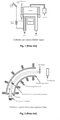
- An example of a CAPVD process is the Sablev type cathodic arc source which comprises a short cylindrical shape electrical conductive target at the cathodic material with one open end, which is shown in Fig. 1 [Prior Art].
- the anode for the apparatus can be either the vacuum chamber wall or a discrete anode.
- Arc spots are generated by mechanical trigger (or igniter) striking an open end of the cathodic material making a temporarily short circuit between the cathodic material and anode. After the arc spots have been generated they can be steered in defined areas of the cathode or move randomly over the cathode surface depending on the nature and orientation of the magnetic field around or near the cathode material.
- the conditions of the CAPVD process can sometimes be such that un-reacted metal from the cathodic material can form metal particles in the coating that are referred to as macroparticles.
- the presence of these macroparticles is considered a structural defect in the coating, and can lead to cracks and fissures that weaken the coating.
- CAPVD processes are optimized to avoid the formation of these macroparticles or filters are used to remove them.
- An example of a CAPVD process that uses such a filter is the Aksenov quarter-torus duct macroparticle filter, shown in Fig.
- the CAPVD process can be modified so that macroparticles can be shaped, sized, composition altered and/or quantified to provide desired properties to the coating.
- desired properties are lubrication, hydrophobic, hydrophilic, corrosion resistance, erosion resistance, surface texture, electrical resistance or any other desired property.
- the macroparticles are formed by the CAPVD process.
- Objectives of the invention can be provided by a method of forming a coating on an airfoil comprising:
- the method of forming a coating on the airfoil comprising: forming liquid, semi-solid, or solid macroparticles by applying a second arc source to a second cathodic material under conditions to form the macroparticles of the second cathodic material so that the macroparticles embed into or onto the coating.
- a coated aerofoil comprising:
- An exemplary CAPVD apparatus 2 is shown in Fig. 3 having a chamber 6 and a source of gas 9 connected to the chamber 6. Three cathodic materials A, B and C are shown, however, any number of cathodic materials can be used.
- the chamber has a turntable 4, upon which the work piece 8 is placed. During operation an arc is generated on each of the cathodic materials A, B and C to form an associated stream 3, 5 and 7 in the general shape of a cone.
- the turntable 4 turns during operation exposing the work piece 8 to each of the streams 3, 5 and 7.
- the present invention is not limited by this exemplary CAPVD apparatus 2, and any other desired CAPVD apparatus may be used to practice the claimed invention.
- At least one of the streams 3, 5 and 7 comprises atoms of at least one cathodic material A, B or C.
- the atoms form a coating on the work piece 8.
- the atoms can also react with the gas 9 supplied to the chamber and/or atoms from other streams to form a compound coating.
- the coating can comprise titanium nitride.
- the work piece 8 to be coated is an aircraft part, more particularly an airfoil.
- the airfoil 8 can be formed of any desired material, such as steel, nickel and titanium and alloys thereof.
- cathodic materials examples include titanium, aluminum, chromium and mixtures thereof. Titanium and aluminum are preferred.
- suitable gases include nitrogen and argon, and mixtures thereof. While nitrogen and argon are preferred, other gases, such as hydrocarbons, for example acetylene, or oxygen and any other gas, can be used to provide desired properties to the macroparticles and/or coating.
- the process is conducted so that at least one of the streams contains macroparticles comprising a solid, semi-solid or liquid state of the cathodic material, which embed into and/or onto the coating.
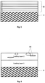
- An example of a coating 32 formed on the airfoil 8 is shown in Fig. 4 .
- Macroparticles 34 and 36 are shown as being embedded into and/or onto the coating 32.
- the properties and composition of the macroparticles can be adjusted by selecting the cathodic materials and/or gases to provide the desired properties and composition.
- the size, shape, and/or quantity of macroparticles can be varied by adjusting the process conditions, such as the amperage and/or gas composition. In general, the greater the amperage the larger the quantity of particles, the more liquid the particles will be when formed, and the more lenticular the particles will be when they are deposited on the surface.
- spherical macroparticles 34 can be formed by using a high melting temperature material and/or adjusting the arc conditions so that the macroparticles 34 formed are in a solid or semi-solid state when contacting the coating 32 so that a spherical shape is maintained.
- high melting materials include titanium. zirconium and chromium and mixtures of titanium, zirconium and chromium with other elements. The use of spherical macroparticles 34 generally results in rough surface on the coating.
- lenticular macroparticles 36 can be formed by using a low melting temperature material and/or adjusting the arc conditions so that the macroparticles 36 formed are in a liquid state when contacting the coating 32 so that the macroparticles 36 flatten during solidification of the macroparticles 36.
- low melting materials include aluminum and mixtures of aluminum with other elements. If the long axis of the lenticular macroparticle 36 is aligned substantially parallel with the coating surface 32, the coating surface 32 will be smooth.
- the use of aluminum macroparticles 36 having a flat lenticular shape has been found to reduce the formation of conical growth defects that normally form above spherical macroparticles 34.
- the macroparticles 34, 36 can be formed of materials selected to provide a desired property to the coating 32.
- the macroparticles 34, 36 can be formed from aluminum or a material having a high aluminum content.
- the corrosion resistance can be further enhanced by the formation of aluminum hydroxide, which forms in corrosive environments and blocks pores and crevices and in so doing prevents corrosive agents from reaching the substrate, in addition providing self-healing properties.
- a lubricious material such as molybdenum disulphide, vanadium, or vanadium nitride, can be used as the particle material 34, 36 to provide the coating with greater lubricity.
- Molybdenum disulphide is a solid-state lubricant used widely in the aerospace industry to reduce wear. Vanadium oxidizes at room temperature and vanadium nitride oxidizes at higher temperatures and under wear conditions to form vanadium oxide which is highly lubricious. Without being bound by any theory it is believed that the presence of macroparticles comprising materials such as vanadium or molybdenum disulfide within the coating enhances the lubricious nature of the coating to reduce the coefficient of friction and wear rate.
- the macroparticles can also be constructed to provide hydrophilic, hydrophobic and/or catalytic properties to the coating.
- the macroparticles can be provided with the desired properties by selecting cathodic materials and/or gasses to provide metals, alloys or compounds in the macroparticles having the desired properties, which properties are provided to the coating by the presence of the macroparticles therein.
- the macroparticles can be constructed to lower the corrosion potential of the coating to below that of the workpiece.
- the macroparticles, having a high aluminum content comprise at least 70 at% aluminum, preferably at least 80 at% aluminum, and more preferably at least 90 at% aluminum, TiAIN coatings.
- a top layer comprising a continuous phase of AIN that surrounds macroparticles of free aluminum can provide beneficial sacrificial corrosion properties relative to steels in the galvanic series in seawater.
- cathodic materials A, B and C are shown in the same plane as the airfoil 8 in Fig. 3 , if desired, the cathodic materials A, B and C can be in any desired location.
- a cathodic material can be disposed over the coating 32 being formed so that the macroparticles sputter or splat onto the coating as it is being formed.
- More than one coating layer can be applied to the airfoil to form the coating 32, as shown in Fig. 5 .
- the different layers can provide different functionalities.
- the macroparticles can be applied to the coating 32 at any time during the process, such as before the coating 32 is applied, during application of the coating 32 or different layers of the coating, and/or after the coating 32 is formed on the airfoil 8.
- Two coating layers were applied to a work piece using the following conditions.
- Reducing the partial pressure of N 2 during the deposition of layer 2 increased the size of the aluminum macro-particles 40 as shown in Fig. 6 . Also the size of the macroparticles can be increased by reducing the total pressure.
- the free aluminum provides sacrificial corrosion resistance to the coating and substrate.
Landscapes
- Chemical & Material Sciences (AREA)
- Engineering & Computer Science (AREA)
- Materials Engineering (AREA)
- Mechanical Engineering (AREA)
- Chemical Kinetics & Catalysis (AREA)
- Metallurgy (AREA)
- Organic Chemistry (AREA)
- General Engineering & Computer Science (AREA)
- Physical Vapour Deposition (AREA)
Description
- The invention relates to a cathodic arc method of making a coating containing macroparticles and a coating containing macroparticles.
- Cathodic Arc Physical Vapor Deposition processes (CAPVD) for applying coatings to a surface of a work piece are now well known. CAPVD is also known as ion plasma deposition, as described in
U.S. Patent No. 6,797,335 ,U.S. Patent Applications 2007/259427 ,2002/046941 or2013/052477 . - The CAPVD process is generally conducted by striking an arc against the surface of a metallic cathodic target material that vaporizes material from the surface. The vaporized material is released in the form of highly ionized plasma (atoms) that can react with a gas on a work piece to form a coating. An example is titanium (vaporized from the metallic cathodic material) and nitrogen (the gas) to form a titanium nitride (TiN) coating on the work piece. Another example is aluminumtitanium-nitride (AITiN or TiAIN). These coatings are very hard and highly resistant to erosion.
- An example of a CAPVD process is the Sablev type cathodic arc source which comprises a short cylindrical shape electrical conductive target at the cathodic material with one open end, which is shown in
Fig. 1 [Prior Art]. The anode for the apparatus can be either the vacuum chamber wall or a discrete anode. Arc spots are generated by mechanical trigger (or igniter) striking an open end of the cathodic material making a temporarily short circuit between the cathodic material and anode. After the arc spots have been generated they can be steered in defined areas of the cathode or move randomly over the cathode surface depending on the nature and orientation of the magnetic field around or near the cathode material. - The conditions of the CAPVD process can sometimes be such that un-reacted metal from the cathodic material can form metal particles in the coating that are referred to as macroparticles. The presence of these macroparticles is considered a structural defect in the coating, and can lead to cracks and fissures that weaken the coating. Thus, CAPVD processes are optimized to avoid the formation of these macroparticles or filters are used to remove them. An example of a CAPVD process that uses such a filter is the Aksenov quarter-torus duct macroparticle filter, shown in
Fig. 2 [Prior Art], which consists of a quarter-torus duct bent at 90 degrees from the arc source and the plasma is guided out of the duct by principle of plasma optics, whereas the macroparticles continue on a straight path unaffected by the magnetic fields of the duct. - We have now found that the CAPVD process can be modified so that macroparticles can be shaped, sized, composition altered and/or quantified to provide desired properties to the coating. Examples of desired properties are lubrication, hydrophobic, hydrophilic, corrosion resistance, erosion resistance, surface texture, electrical resistance or any other desired property. The macroparticles are formed by the CAPVD process.
- Objectives of the invention can be provided by a method of forming a coating on an airfoil comprising:
- inserting a airfoil into a cathodic arc apparatus;
- vaporizing at least one cathodic material by applying an arc to the cathodic material to form atoms ions and macroparticles of the cathodic material in an atmosphere within the apparatus so that the atoms form a coating on the airfoil;
- the parameters of the arc are adjusted to form liquid, semi-solid, or solid macroparticles of the cathodic material so that the macroparticles embed into or onto the coating, wherein the cathodic material is deposited as a metal and/or in reactive gas to form a nitride, carbide, oxide or mixture thereof, and
- wherein the cathodic material or its nitride, carbide, oxide or mixture thereof has at least one property of sacrificial corrosion resistance or self- healing, wherein the macroparticles comprise at least 70 at% aluminum to provide the coating with a sacrificial component that is less noble than the airfoil.
- According to a preferred embodiment of the invention, the method of forming a coating on the airfoil comprising:
forming liquid, semi-solid, or solid macroparticles by applying a second arc source to a second cathodic material under conditions to form the macroparticles of the second cathodic material so that the macroparticles embed into or onto the coating. - Objectives of the invention can be further obtained by a coated aerofoil comprising:
- an aerofoil having a surface; and
- a coating formed on the surface of the airfoil and having embedded macroparticles, wherein the macroparticles are spherical and the surface of the coating is rough,
- or wherein the macroparticles are lenticular and a long axis of the lenticular macroparticles is aligned substantially parallel with the surface of the coating and is smooth,
- and wherein the macroparticles comprise at least 70 at% aluminum to provide the coating with a sacrificial component that is less noble than the workpiece.
-
-
Fig. 1 illustrates a prior art cathodic arc process apparatus; -
Fig. 2 illustrates a prior art cathodic arc process apparatus; -
Fig. 3 illustrates a cathodic arc process apparatus; -
Fig. 4 illustrates a coating having macroparticles; -
Fig. 5 illustrates a coating having multiple layers; and -
Fig. 6 illustrates a coating having multiple layers with macroparticles. - The invention will now be explained with reference to that attached non-limiting Figs.
- An
exemplary CAPVD apparatus 2 is shown inFig. 3 having achamber 6 and a source ofgas 9 connected to thechamber 6. Three cathodic materials A, B and C are shown, however, any number of cathodic materials can be used. The chamber has a turntable 4, upon which thework piece 8 is placed. During operation an arc is generated on each of the cathodic materials A, B and C to form an associatedstream work piece 8 to each of thestreams exemplary CAPVD apparatus 2, and any other desired CAPVD apparatus may be used to practice the claimed invention. - At least one of the
streams work piece 8. The atoms can also react with thegas 9 supplied to the chamber and/or atoms from other streams to form a compound coating. For example, if the atoms comprise titanium and the gas comprises nitrogen, the coating can comprise titanium nitride. - The
work piece 8 to be coated is an aircraft part, more particularly an airfoil. Theairfoil 8 can be formed of any desired material, such as steel, nickel and titanium and alloys thereof. - Examples of suitable cathodic materials include titanium, aluminum, chromium and mixtures thereof. Titanium and aluminum are preferred.
- Examples of suitable gases include nitrogen and argon, and mixtures thereof. While nitrogen and argon are preferred, other gases, such as hydrocarbons, for example acetylene, or oxygen and any other gas, can be used to provide desired properties to the macroparticles and/or coating.
- The process is conducted so that at least one of the streams contains macroparticles comprising a solid, semi-solid or liquid state of the cathodic material, which embed into and/or onto the coating. An example of a
coating 32 formed on theairfoil 8 is shown inFig. 4 .Macroparticles coating 32. - The properties and composition of the macroparticles can be adjusted by selecting the cathodic materials and/or gases to provide the desired properties and composition. The size, shape, and/or quantity of macroparticles can be varied by adjusting the process conditions, such as the amperage and/or gas composition. In general, the greater the amperage the larger the quantity of particles, the more liquid the particles will be when formed, and the more lenticular the particles will be when they are deposited on the surface.
- Without being bound by any theory, we believe that
spherical macroparticles 34 can be formed by using a high melting temperature material and/or adjusting the arc conditions so that themacroparticles 34 formed are in a solid or semi-solid state when contacting thecoating 32 so that a spherical shape is maintained. Examples of high melting materials include titanium. zirconium and chromium and mixtures of titanium, zirconium and chromium with other elements. The use ofspherical macroparticles 34 generally results in rough surface on the coating. - Without being bound by any theory, we believe that
lenticular macroparticles 36 can be formed by using a low melting temperature material and/or adjusting the arc conditions so that themacroparticles 36 formed are in a liquid state when contacting thecoating 32 so that themacroparticles 36 flatten during solidification of themacroparticles 36. Examples of low melting materials include aluminum and mixtures of aluminum with other elements. If the long axis of thelenticular macroparticle 36 is aligned substantially parallel with thecoating surface 32, thecoating surface 32 will be smooth. The use ofaluminum macroparticles 36 having a flat lenticular shape has been found to reduce the formation of conical growth defects that normally form abovespherical macroparticles 34. - The
macroparticles coating 32. - To enhance the corrosion resistance of the coating, the
macroparticles - A lubricious material, such as molybdenum disulphide, vanadium, or vanadium nitride, can be used as the
particle material - The macroparticles can also be constructed to provide hydrophilic, hydrophobic and/or catalytic properties to the coating. The macroparticles can be provided with the desired properties by selecting cathodic materials and/or gasses to provide metals, alloys or compounds in the macroparticles having the desired properties, which properties are provided to the coating by the presence of the macroparticles therein.
- The macroparticles can be constructed to lower the corrosion potential of the coating to below that of the workpiece. The macroparticles, having a high aluminum content, comprise at least 70 at% aluminum, preferably at least 80 at% aluminum, and more preferably at least 90 at% aluminum, TiAIN coatings. Without being bound by any theory, it is believed that a top layer comprising a continuous phase of AIN that surrounds macroparticles of free aluminum can provide beneficial sacrificial corrosion properties relative to steels in the galvanic series in seawater.
- While the cathodic materials A, B and C are shown in the same plane as the
airfoil 8 inFig. 3 , if desired, the cathodic materials A, B and C can be in any desired location. For example, a cathodic material can be disposed over thecoating 32 being formed so that the macroparticles sputter or splat onto the coating as it is being formed. - More than one coating layer can be applied to the airfoil to form the
coating 32, as shown inFig. 5 . The different layers can provide different functionalities. Furthermore, the macroparticles can be applied to thecoating 32 at any time during the process, such as before thecoating 32 is applied, during application of thecoating 32 or different layers of the coating, and/or after thecoating 32 is formed on theairfoil 8. - The invention will now be further described with reference to the following non-limiting experimental examples.
- Two coating layers were applied to a work piece using the following conditions.
-
Coating layer 1 - 3 Cathodes
- 2 × Al
- 1 × (TiAl)
- Gas = N2
-
Coating layer 2 - 2 Cathodes
- 2 × Al
- Gas = N2 +Ar
- Reducing the partial pressure of N2 during the deposition of
layer 2 increased the size of the aluminum macro-particles 40 as shown inFig. 6 . Also the size of the macroparticles can be increased by reducing the total pressure. The free aluminum provides sacrificial corrosion resistance to the coating and substrate. - While the claimed invention has been described in detail and with reference to specific embodiments thereof, it will be apparent to one of ordinary skill in the art that various changes and modifications can be made to the claimed invention without departing from the scope thereof.
Claims (10)
- A method of forming a coating (32) on an airfoil (8) comprising:- inserting an airfoil (8) into a cathodic arc apparatus (2);- vaporizing at least one cathodic material (A, B, C) by applying an arc (3, 5, 7) to the cathodic material to form atoms ions and macroparticles (34, 36) of the cathodic material (A, B, C) in an atmosphere within the apparatus (2) so that the atoms form a coating (32) on the airfoil (8);
characterized in that- the parameters of the arc (3, 5, 7) are adjusted to form liquid, semi-solid, or solid macroparticles (34, 36) of the cathodic material (A, B, C) so that the macroparticles (34, 36) embed into or onto the coating (32), wherein the cathodic material (A, B, C) is deposited as a metal and/or in reactive gas to form a nitride, carbide, oxide or mixture thereof, and
wherein the cathodic material (A, B, C) or its nitride, carbide, oxide or mixture thereof has at least one property of sacrificial corrosion resistance or self-healing, wherein the macroparticles (34, 36) comprise at least 70 at% aluminum to provide the coating (32) with a sacrificial component that is less noble than the airfoil (8). - The method according to claim 1, wherein the cathodic material (A, B, C) is selected or the arc (3, 5, 7) is applied in a manner to provide lenticular macroparticles (36).
- The method according to claim 1, wherein the macroparticles (34, 36) comprise at least 90 at% aluminum to provide the coating (32) with a sacrificial component that is less noble than the airfoil (8).
- The method according to claim 1, wherein the cathodic material (A, B, C) is selected or the arc (3, 5, 7) is applied to provide macroparticles (34) having a spherical shape.
- The method according to claim 1, further comprising forming liquid, semi-solid, or solid macroparticles (34, 36) by applying a second arc source to a second cathodic material under conditions to form the macroparticles (40) of the second material so that the macroparticles (40) embed into or onto the coating (32).
- The method according to claim 5, wherein the coating (32) comprises multiple layers.
- The method according to claim 5, wherein the macroparticles (40) of the second cathodic material comprise at least 90 at% aluminum to provide the coating (32) with a sacrificial component that is less noble than the airfoil (8).
- The method according to claim 5, wherein the second cathodic material is selected or the arc is applied to provide macroparticles (40) having a spherical shape.
- A coated airfoil comprising:- an airfoil (8) having a surface; and- a coating (32) formed on the surface of the airfoil (8) and having embedded macroparticles (34, 36), wherein the macroparticles (34) are spherical and the surface of the coating is rough,or wherein the macroparticles (36) are lenticular and a long axis of the lenticular macroparticles is aligned substantially parallel with the surface of the coating (32) and is smooth,and wherein the macroparticles (34, 36) comprise at least 70 at% aluminum to provide the coating (32) with a sacrificial component that is less noble than the airfoil (8).
- The coated airfoil according to claim 9 wherein the macroparticles (34, 36) comprise at least 90 at% aluminum to provide the coating (32) with a sacrificial component that is less noble than the airfoil (8).
Applications Claiming Priority (2)
| Application Number | Priority Date | Filing Date | Title |
|---|---|---|---|
| US201361867751P | 2013-08-20 | 2013-08-20 | |
| PCT/CA2014/000627 WO2015024098A1 (en) | 2013-08-20 | 2014-08-18 | Coating containing macroparticles and cathodic arc process of making the coating |
Publications (3)
| Publication Number | Publication Date |
|---|---|
| EP3036353A1 EP3036353A1 (en) | 2016-06-29 |
| EP3036353A4 EP3036353A4 (en) | 2017-09-06 |
| EP3036353B1 true EP3036353B1 (en) | 2022-01-26 |
Family
ID=52482868
Family Applications (1)
| Application Number | Title | Priority Date | Filing Date |
|---|---|---|---|
| EP14837670.0A Active EP3036353B1 (en) | 2013-08-20 | 2014-08-18 | Coating containing macroparticles and cathodic arc process of making the coating |
Country Status (5)
| Country | Link |
|---|---|
| US (2) | US10465278B2 (en) |
| EP (1) | EP3036353B1 (en) |
| JP (2) | JP6400708B2 (en) |
| CA (1) | CA2920906A1 (en) |
| WO (1) | WO2015024098A1 (en) |
Families Citing this family (4)
| Publication number | Priority date | Publication date | Assignee | Title |
|---|---|---|---|---|
| CN110785163B (en) | 2017-05-23 | 2023-09-05 | 法尔米瓦股份公司 | Foam-forming compositions for delivering active agents to body cavities |
| US10830064B2 (en) * | 2017-06-12 | 2020-11-10 | Raytheon Technologies Corporation | Hollow titanium airfoil with titanium coating |
| DE102021109537A1 (en) | 2021-04-15 | 2022-10-20 | Leibniz-Institut für Oberflächenmodifizierung e.V. | Arc plasma source with liquid cathode |
| CN113564523A (en) * | 2021-07-13 | 2021-10-29 | 南京邮电大学 | A preparation device of carbon-plated porous aluminum current collector and preparation method thereof |
Family Cites Families (18)
| Publication number | Priority date | Publication date | Assignee | Title |
|---|---|---|---|---|
| US4898368A (en) * | 1988-08-26 | 1990-02-06 | Union Carbide Corporation | Wear resistant metallurgical tuyere |
| US5681575A (en) * | 1992-05-19 | 1997-10-28 | Westaim Technologies Inc. | Anti-microbial coating for medical devices |
| JPH06212406A (en) * | 1993-01-19 | 1994-08-02 | Nissin Electric Co Ltd | Arc discharge vacuum deposition equipment |
| JPH06306581A (en) * | 1993-04-22 | 1994-11-01 | Kobe Steel Ltd | Film for sliding surface and its formation |
| JP2000239829A (en) | 1999-02-17 | 2000-09-05 | Sumitomo Metal Mining Co Ltd | Material with solid lubrication film |
| RU2161661C1 (en) | 1999-08-16 | 2001-01-10 | Падеров Анатолий Николаевич | Method of applying wear-resistant coatings and improvement of durability of parts |
| JP4679004B2 (en) * | 2000-09-26 | 2011-04-27 | 新明和工業株式会社 | Arc evaporation source apparatus, driving method thereof, and ion plating apparatus |
| CA2635062C (en) | 2002-12-18 | 2010-10-26 | Chameleon Scientific Corporation | Antimicrobial coating methods |
| US20040126492A1 (en) * | 2002-12-30 | 2004-07-01 | Weaver Scott Andrew | Method and apparatus for using ion plasma deposition to produce coating |
| JP2004316850A (en) * | 2003-04-18 | 2004-11-11 | Toyota Motor Corp | Sliding member and manufacturing method thereof |
| DE102005021927A1 (en) | 2005-05-12 | 2006-11-16 | Fette Gmbh | Alloy body as a target for the PVD process, process for producing the alloyed body and PVD process with the alloyed body |
| US20070259427A1 (en) * | 2006-03-27 | 2007-11-08 | Storey Daniel M | Modified surfaces for attachment of biological materials |
| US20080102296A1 (en) * | 2006-10-26 | 2008-05-01 | Farshad Ghasripoor | Erosion resistant coatings and methods of making |
| US8790789B2 (en) * | 2008-05-29 | 2014-07-29 | General Electric Company | Erosion and corrosion resistant coatings, methods and articles |
| JP5562336B2 (en) | 2008-08-17 | 2014-07-30 | エリコン・トレーディング・アクチェンゲゼルシャフト,トリュープバッハ | Use of a target for arc evaporation and method of manufacturing a target suitable for said use |
| RU2560480C2 (en) * | 2010-02-04 | 2015-08-20 | Эрликон Трейдинг Аг, Трюббах | CUTTING TOOLS WITH SANDWICHED COATINGS OF Al-Cr-B/Ti-Al-N |
| US9765635B2 (en) * | 2010-05-28 | 2017-09-19 | Nano-Product Engineering, Llc. | Erosion and corrosion resistant protective coatings for turbomachinery |
| JP2013082058A (en) * | 2011-09-28 | 2013-05-09 | Mitsubishi Materials Corp | Surface coated cutting tool excellent in chipping resistance and wearing resistance |
-
2014
- 2014-08-18 EP EP14837670.0A patent/EP3036353B1/en active Active
- 2014-08-18 US US14/911,038 patent/US10465278B2/en active Active
- 2014-08-18 JP JP2016535279A patent/JP6400708B2/en active Active
- 2014-08-18 CA CA2920906A patent/CA2920906A1/en not_active Abandoned
- 2014-08-18 WO PCT/CA2014/000627 patent/WO2015024098A1/en not_active Ceased
-
2018
- 2018-09-05 JP JP2018165605A patent/JP6892423B2/en active Active
-
2019
- 2019-09-25 US US16/581,975 patent/US20200032384A1/en not_active Abandoned
Also Published As
| Publication number | Publication date |
|---|---|
| EP3036353A4 (en) | 2017-09-06 |
| US10465278B2 (en) | 2019-11-05 |
| JP6400708B2 (en) | 2018-10-03 |
| US20160201186A1 (en) | 2016-07-14 |
| US20200032384A1 (en) | 2020-01-30 |
| JP2016528391A (en) | 2016-09-15 |
| WO2015024098A1 (en) | 2015-02-26 |
| EP3036353A1 (en) | 2016-06-29 |
| CA2920906A1 (en) | 2015-02-26 |
| JP2018188741A (en) | 2018-11-29 |
| JP6892423B2 (en) | 2021-06-23 |
Similar Documents
| Publication | Publication Date | Title |
|---|---|---|
| US20200032384A1 (en) | Coating containing macroparticles and cathodic arc process of making the coating | |
| Xiao et al. | Nanostructured TiN coating prepared by reactive plasma spraying in atmosphere | |
| CN104508171B (en) | Coat system, the matrix of coating and the method with coat system coating matrix surface | |
| Parameswaran et al. | Titanium nitride coating for aero engine compressor gas path components | |
| KR102208344B1 (en) | Hard material layers with selected thermal conductivity | |
| JP7507766B2 (en) | Corrosion-resistant carbon coating | |
| CN104379796A (en) | Method for depositing a coating and a coated cutting tool | |
| JP6525310B2 (en) | Coated tools | |
| US20110020079A1 (en) | Coating process, workpiece or tool and its use | |
| JPS63255358A (en) | At least two types of metal nitride mixed layer and its formation method | |
| JP2014509262A (en) | Metal plate hot forming or hot stamping tool with CrSiN coating | |
| WO2009038532A1 (en) | Method of producing a layer by arc-evaporation from ceramic cathodes | |
| KR102335906B1 (en) | TiCN with reduced growth defects by HiPIMS | |
| CN108754406A (en) | A kind of die surface compounding method | |
| JP6523283B2 (en) | Molybdenum nitride with excellent sliding properties and adequate hardness | |
| Ali et al. | Hard coating deposits: incompatible working energy and forced behaviours of gaseous and solid atoms | |
| KR20140065447A (en) | Coated cutting tool | |
| Kiryukhantsev-Korneev et al. | Healing effect in coatings deposited by hybrid technology of vacuum electro-spark alloying, pulsed cathodic arc evaporation, and magnetron sputtering using Cr3C2-NiAl electrodes | |
| WO2010140058A1 (en) | Electrodes incorporating aluminium coated particles and methods thereof | |
| Urbahs et al. | Evaluation of the Physical and Mechanical Characteristics of Ion-Plasma Antifriction Coatings Based on Ti-Cu | |
| Latushkina et al. | Formation of Corrosion‐Resistant Nitride Coatings Based on Ti–Al–Cr–Fe–Ni High‐Entropy Alloy | |
| KR20200066489A (en) | Deposition Method of Super Coating Flim Having High-Adhesion and High-Hardness | |
| JP2013044382A (en) | Marine piston ring and manufacturing method thereof | |
| Chernogor et al. | Influence of bias voltage on structure and mechanical properties of TiCrN-Mo2N-Ni coatings | |
| JPH05125521A (en) | Sliding material and manufacturing method thereof |
Legal Events
| Date | Code | Title | Description |
|---|---|---|---|
| PUAI | Public reference made under article 153(3) epc to a published international application that has entered the european phase |
Free format text: ORIGINAL CODE: 0009012 |
|
| 17P | Request for examination filed |
Effective date: 20160318 |
|
| AK | Designated contracting states |
Kind code of ref document: A1 Designated state(s): AL AT BE BG CH CY CZ DE DK EE ES FI FR GB GR HR HU IE IS IT LI LT LU LV MC MK MT NL NO PL PT RO RS SE SI SK SM TR |
|
| AX | Request for extension of the european patent |
Extension state: BA ME |
|
| DAX | Request for extension of the european patent (deleted) | ||
| A4 | Supplementary search report drawn up and despatched |
Effective date: 20170803 |
|
| RIC1 | Information provided on ipc code assigned before grant |
Ipc: C23C 14/32 20060101ALI20170728BHEP Ipc: C23C 14/06 20060101ALI20170728BHEP Ipc: C23C 14/34 20060101AFI20170728BHEP Ipc: C23C 14/14 20060101ALI20170728BHEP |
|
| STAA | Information on the status of an ep patent application or granted ep patent |
Free format text: STATUS: EXAMINATION IS IN PROGRESS |
|
| 17Q | First examination report despatched |
Effective date: 20180816 |
|
| REG | Reference to a national code |
Ref country code: DE Ref legal event code: R079 Ref document number: 602014082345 Country of ref document: DE Free format text: PREVIOUS MAIN CLASS: C23C0014340000 Ipc: C23C0014060000 |
|
| RIC1 | Information provided on ipc code assigned before grant |
Ipc: C23C 14/06 20060101AFI20210720BHEP Ipc: C23C 14/32 20060101ALI20210720BHEP |
|
| GRAP | Despatch of communication of intention to grant a patent |
Free format text: ORIGINAL CODE: EPIDOSNIGR1 |
|
| STAA | Information on the status of an ep patent application or granted ep patent |
Free format text: STATUS: GRANT OF PATENT IS INTENDED |
|
| INTG | Intention to grant announced |
Effective date: 20210916 |
|
| RIN1 | Information on inventor provided before grant (corrected) |
Inventor name: GUETRE, STEVE Inventor name: MENDEZ, MANUEL Inventor name: TZANEV, STEFAN Inventor name: DURHAM, SIMON |
|
| GRAS | Grant fee paid |
Free format text: ORIGINAL CODE: EPIDOSNIGR3 |
|
| GRAA | (expected) grant |
Free format text: ORIGINAL CODE: 0009210 |
|
| STAA | Information on the status of an ep patent application or granted ep patent |
Free format text: STATUS: THE PATENT HAS BEEN GRANTED |
|
| AK | Designated contracting states |
Kind code of ref document: B1 Designated state(s): AL AT BE BG CH CY CZ DE DK EE ES FI FR GB GR HR HU IE IS IT LI LT LU LV MC MK MT NL NO PL PT RO RS SE SI SK SM TR |
|
| REG | Reference to a national code |
Ref country code: GB Ref legal event code: FG4D |
|
| REG | Reference to a national code |
Ref country code: CH Ref legal event code: EP |
|
| REG | Reference to a national code |
Ref country code: AT Ref legal event code: REF Ref document number: 1465363 Country of ref document: AT Kind code of ref document: T Effective date: 20220215 |
|
| REG | Reference to a national code |
Ref country code: IE Ref legal event code: FG4D |
|
| REG | Reference to a national code |
Ref country code: DE Ref legal event code: R096 Ref document number: 602014082345 Country of ref document: DE |
|
| REG | Reference to a national code |
Ref country code: LT Ref legal event code: MG9D |
|
| REG | Reference to a national code |
Ref country code: NL Ref legal event code: MP Effective date: 20220126 |
|
| REG | Reference to a national code |
Ref country code: AT Ref legal event code: MK05 Ref document number: 1465363 Country of ref document: AT Kind code of ref document: T Effective date: 20220126 |
|
| PG25 | Lapsed in a contracting state [announced via postgrant information from national office to epo] |
Ref country code: NL Free format text: LAPSE BECAUSE OF FAILURE TO SUBMIT A TRANSLATION OF THE DESCRIPTION OR TO PAY THE FEE WITHIN THE PRESCRIBED TIME-LIMIT Effective date: 20220126 |
|
| PG25 | Lapsed in a contracting state [announced via postgrant information from national office to epo] |
Ref country code: SE Free format text: LAPSE BECAUSE OF FAILURE TO SUBMIT A TRANSLATION OF THE DESCRIPTION OR TO PAY THE FEE WITHIN THE PRESCRIBED TIME-LIMIT Effective date: 20220126 Ref country code: RS Free format text: LAPSE BECAUSE OF FAILURE TO SUBMIT A TRANSLATION OF THE DESCRIPTION OR TO PAY THE FEE WITHIN THE PRESCRIBED TIME-LIMIT Effective date: 20220126 Ref country code: PT Free format text: LAPSE BECAUSE OF FAILURE TO SUBMIT A TRANSLATION OF THE DESCRIPTION OR TO PAY THE FEE WITHIN THE PRESCRIBED TIME-LIMIT Effective date: 20220526 Ref country code: NO Free format text: LAPSE BECAUSE OF FAILURE TO SUBMIT A TRANSLATION OF THE DESCRIPTION OR TO PAY THE FEE WITHIN THE PRESCRIBED TIME-LIMIT Effective date: 20220426 Ref country code: LT Free format text: LAPSE BECAUSE OF FAILURE TO SUBMIT A TRANSLATION OF THE DESCRIPTION OR TO PAY THE FEE WITHIN THE PRESCRIBED TIME-LIMIT Effective date: 20220126 Ref country code: HR Free format text: LAPSE BECAUSE OF FAILURE TO SUBMIT A TRANSLATION OF THE DESCRIPTION OR TO PAY THE FEE WITHIN THE PRESCRIBED TIME-LIMIT Effective date: 20220126 Ref country code: ES Free format text: LAPSE BECAUSE OF FAILURE TO SUBMIT A TRANSLATION OF THE DESCRIPTION OR TO PAY THE FEE WITHIN THE PRESCRIBED TIME-LIMIT Effective date: 20220126 Ref country code: BG Free format text: LAPSE BECAUSE OF FAILURE TO SUBMIT A TRANSLATION OF THE DESCRIPTION OR TO PAY THE FEE WITHIN THE PRESCRIBED TIME-LIMIT Effective date: 20220426 |
|
| PG25 | Lapsed in a contracting state [announced via postgrant information from national office to epo] |
Ref country code: PL Free format text: LAPSE BECAUSE OF FAILURE TO SUBMIT A TRANSLATION OF THE DESCRIPTION OR TO PAY THE FEE WITHIN THE PRESCRIBED TIME-LIMIT Effective date: 20220126 Ref country code: LV Free format text: LAPSE BECAUSE OF FAILURE TO SUBMIT A TRANSLATION OF THE DESCRIPTION OR TO PAY THE FEE WITHIN THE PRESCRIBED TIME-LIMIT Effective date: 20220126 Ref country code: GR Free format text: LAPSE BECAUSE OF FAILURE TO SUBMIT A TRANSLATION OF THE DESCRIPTION OR TO PAY THE FEE WITHIN THE PRESCRIBED TIME-LIMIT Effective date: 20220427 Ref country code: FI Free format text: LAPSE BECAUSE OF FAILURE TO SUBMIT A TRANSLATION OF THE DESCRIPTION OR TO PAY THE FEE WITHIN THE PRESCRIBED TIME-LIMIT Effective date: 20220126 Ref country code: AT Free format text: LAPSE BECAUSE OF FAILURE TO SUBMIT A TRANSLATION OF THE DESCRIPTION OR TO PAY THE FEE WITHIN THE PRESCRIBED TIME-LIMIT Effective date: 20220126 |
|
| PG25 | Lapsed in a contracting state [announced via postgrant information from national office to epo] |
Ref country code: IS Free format text: LAPSE BECAUSE OF FAILURE TO SUBMIT A TRANSLATION OF THE DESCRIPTION OR TO PAY THE FEE WITHIN THE PRESCRIBED TIME-LIMIT Effective date: 20220526 |
|
| REG | Reference to a national code |
Ref country code: DE Ref legal event code: R097 Ref document number: 602014082345 Country of ref document: DE |
|
| PG25 | Lapsed in a contracting state [announced via postgrant information from national office to epo] |
Ref country code: SM Free format text: LAPSE BECAUSE OF FAILURE TO SUBMIT A TRANSLATION OF THE DESCRIPTION OR TO PAY THE FEE WITHIN THE PRESCRIBED TIME-LIMIT Effective date: 20220126 Ref country code: SK Free format text: LAPSE BECAUSE OF FAILURE TO SUBMIT A TRANSLATION OF THE DESCRIPTION OR TO PAY THE FEE WITHIN THE PRESCRIBED TIME-LIMIT Effective date: 20220126 Ref country code: RO Free format text: LAPSE BECAUSE OF FAILURE TO SUBMIT A TRANSLATION OF THE DESCRIPTION OR TO PAY THE FEE WITHIN THE PRESCRIBED TIME-LIMIT Effective date: 20220126 Ref country code: EE Free format text: LAPSE BECAUSE OF FAILURE TO SUBMIT A TRANSLATION OF THE DESCRIPTION OR TO PAY THE FEE WITHIN THE PRESCRIBED TIME-LIMIT Effective date: 20220126 Ref country code: DK Free format text: LAPSE BECAUSE OF FAILURE TO SUBMIT A TRANSLATION OF THE DESCRIPTION OR TO PAY THE FEE WITHIN THE PRESCRIBED TIME-LIMIT Effective date: 20220126 Ref country code: CZ Free format text: LAPSE BECAUSE OF FAILURE TO SUBMIT A TRANSLATION OF THE DESCRIPTION OR TO PAY THE FEE WITHIN THE PRESCRIBED TIME-LIMIT Effective date: 20220126 |
|
| PG25 | Lapsed in a contracting state [announced via postgrant information from national office to epo] |
Ref country code: AL Free format text: LAPSE BECAUSE OF FAILURE TO SUBMIT A TRANSLATION OF THE DESCRIPTION OR TO PAY THE FEE WITHIN THE PRESCRIBED TIME-LIMIT Effective date: 20220126 |
|
| PLBE | No opposition filed within time limit |
Free format text: ORIGINAL CODE: 0009261 |
|
| STAA | Information on the status of an ep patent application or granted ep patent |
Free format text: STATUS: NO OPPOSITION FILED WITHIN TIME LIMIT |
|
| 26N | No opposition filed |
Effective date: 20221027 |
|
| PG25 | Lapsed in a contracting state [announced via postgrant information from national office to epo] |
Ref country code: SI Free format text: LAPSE BECAUSE OF FAILURE TO SUBMIT A TRANSLATION OF THE DESCRIPTION OR TO PAY THE FEE WITHIN THE PRESCRIBED TIME-LIMIT Effective date: 20220126 |
|
| PG25 | Lapsed in a contracting state [announced via postgrant information from national office to epo] |
Ref country code: MC Free format text: LAPSE BECAUSE OF FAILURE TO SUBMIT A TRANSLATION OF THE DESCRIPTION OR TO PAY THE FEE WITHIN THE PRESCRIBED TIME-LIMIT Effective date: 20220126 |
|
| REG | Reference to a national code |
Ref country code: CH Ref legal event code: PL |
|
| PG25 | Lapsed in a contracting state [announced via postgrant information from national office to epo] |
Ref country code: LU Free format text: LAPSE BECAUSE OF NON-PAYMENT OF DUE FEES Effective date: 20220818 Ref country code: LI Free format text: LAPSE BECAUSE OF NON-PAYMENT OF DUE FEES Effective date: 20220831 Ref country code: CH Free format text: LAPSE BECAUSE OF NON-PAYMENT OF DUE FEES Effective date: 20220831 |
|
| REG | Reference to a national code |
Ref country code: BE Ref legal event code: MM Effective date: 20220831 |
|
| PG25 | Lapsed in a contracting state [announced via postgrant information from national office to epo] |
Ref country code: IT Free format text: LAPSE BECAUSE OF FAILURE TO SUBMIT A TRANSLATION OF THE DESCRIPTION OR TO PAY THE FEE WITHIN THE PRESCRIBED TIME-LIMIT Effective date: 20220126 Ref country code: IE Free format text: LAPSE BECAUSE OF NON-PAYMENT OF DUE FEES Effective date: 20220818 |
|
| PG25 | Lapsed in a contracting state [announced via postgrant information from national office to epo] |
Ref country code: BE Free format text: LAPSE BECAUSE OF NON-PAYMENT OF DUE FEES Effective date: 20220831 |
|
| PG25 | Lapsed in a contracting state [announced via postgrant information from national office to epo] |
Ref country code: HU Free format text: LAPSE BECAUSE OF FAILURE TO SUBMIT A TRANSLATION OF THE DESCRIPTION OR TO PAY THE FEE WITHIN THE PRESCRIBED TIME-LIMIT; INVALID AB INITIO Effective date: 20140818 |
|
| PG25 | Lapsed in a contracting state [announced via postgrant information from national office to epo] |
Ref country code: CY Free format text: LAPSE BECAUSE OF FAILURE TO SUBMIT A TRANSLATION OF THE DESCRIPTION OR TO PAY THE FEE WITHIN THE PRESCRIBED TIME-LIMIT Effective date: 20220126 |
|
| PG25 | Lapsed in a contracting state [announced via postgrant information from national office to epo] |
Ref country code: MK Free format text: LAPSE BECAUSE OF FAILURE TO SUBMIT A TRANSLATION OF THE DESCRIPTION OR TO PAY THE FEE WITHIN THE PRESCRIBED TIME-LIMIT Effective date: 20220126 |
|
| PG25 | Lapsed in a contracting state [announced via postgrant information from national office to epo] |
Ref country code: MT Free format text: LAPSE BECAUSE OF FAILURE TO SUBMIT A TRANSLATION OF THE DESCRIPTION OR TO PAY THE FEE WITHIN THE PRESCRIBED TIME-LIMIT Effective date: 20220126 |
|
| PGFP | Annual fee paid to national office [announced via postgrant information from national office to epo] |
Ref country code: DE Payment date: 20250624 Year of fee payment: 12 |
|
| PG25 | Lapsed in a contracting state [announced via postgrant information from national office to epo] |
Ref country code: TR Free format text: LAPSE BECAUSE OF FAILURE TO SUBMIT A TRANSLATION OF THE DESCRIPTION OR TO PAY THE FEE WITHIN THE PRESCRIBED TIME-LIMIT Effective date: 20220126 |
|
| PGFP | Annual fee paid to national office [announced via postgrant information from national office to epo] |
Ref country code: GB Payment date: 20260630 Year of fee payment: 13 |
|
| PGFP | Annual fee paid to national office [announced via postgrant information from national office to epo] |
Ref country code: FR Payment date: 20260608 Year of fee payment: 13 |