EP3036087B1 - Système de revêtement pour imprimante 3d - Google Patents
Système de revêtement pour imprimante 3d Download PDFInfo
- Publication number
- EP3036087B1 EP3036087B1 EP15766065.5A EP15766065A EP3036087B1 EP 3036087 B1 EP3036087 B1 EP 3036087B1 EP 15766065 A EP15766065 A EP 15766065A EP 3036087 B1 EP3036087 B1 EP 3036087B1
- Authority
- EP
- European Patent Office
- Prior art keywords
- coating device
- coater
- coating
- closing
- opening
- Prior art date
- Legal status (The legal status is an assumption and is not a legal conclusion. Google has not performed a legal analysis and makes no representation as to the accuracy of the status listed.)
- Active
Links
- 239000011248 coating agent Substances 0.000 title claims description 87
- 238000000576 coating method Methods 0.000 title claims description 87
- 238000010276 construction Methods 0.000 claims description 84
- 239000012530 fluid Substances 0.000 claims description 38
- 238000004140 cleaning Methods 0.000 claims description 30
- 238000004519 manufacturing process Methods 0.000 claims description 19
- 239000011236 particulate material Substances 0.000 claims description 19
- 239000000463 material Substances 0.000 claims description 10
- 238000000034 method Methods 0.000 claims description 10
- 239000004035 construction material Substances 0.000 claims description 8
- 238000007789 sealing Methods 0.000 claims description 7
- 239000004566 building material Substances 0.000 description 63
- 239000010410 layer Substances 0.000 description 20
- 239000011230 binding agent Substances 0.000 description 12
- 238000007639 printing Methods 0.000 description 11
- 239000003795 chemical substances by application Substances 0.000 description 8
- 239000000203 mixture Substances 0.000 description 8
- 239000004576 sand Substances 0.000 description 7
- 230000013011 mating Effects 0.000 description 5
- 230000001680 brushing effect Effects 0.000 description 4
- 238000005266 casting Methods 0.000 description 4
- 238000009434 installation Methods 0.000 description 4
- 239000000654 additive Substances 0.000 description 3
- 238000004891 communication Methods 0.000 description 3
- 238000013016 damping Methods 0.000 description 3
- 239000007788 liquid Substances 0.000 description 3
- 239000002245 particle Substances 0.000 description 3
- 239000013618 particulate matter Substances 0.000 description 3
- 229920001296 polysiloxane Polymers 0.000 description 3
- 238000007711 solidification Methods 0.000 description 3
- 230000008023 solidification Effects 0.000 description 3
- 229910000831 Steel Inorganic materials 0.000 description 2
- 230000000996 additive effect Effects 0.000 description 2
- 239000012298 atmosphere Substances 0.000 description 2
- 230000015556 catabolic process Effects 0.000 description 2
- 238000006731 degradation reaction Methods 0.000 description 2
- 238000013461 design Methods 0.000 description 2
- 238000007599 discharging Methods 0.000 description 2
- 238000006073 displacement reaction Methods 0.000 description 2
- 229920001971 elastomer Polymers 0.000 description 2
- 239000000806 elastomer Substances 0.000 description 2
- 238000003780 insertion Methods 0.000 description 2
- 230000037431 insertion Effects 0.000 description 2
- 230000002093 peripheral effect Effects 0.000 description 2
- 238000012545 processing Methods 0.000 description 2
- 239000012858 resilient material Substances 0.000 description 2
- 238000000110 selective laser sintering Methods 0.000 description 2
- 239000010959 steel Substances 0.000 description 2
- 238000003860 storage Methods 0.000 description 2
- 239000002344 surface layer Substances 0.000 description 2
- 238000010146 3D printing Methods 0.000 description 1
- 230000001133 acceleration Effects 0.000 description 1
- 239000012190 activator Substances 0.000 description 1
- 238000004026 adhesive bonding Methods 0.000 description 1
- 230000032683 aging Effects 0.000 description 1
- 238000000149 argon plasma sintering Methods 0.000 description 1
- 230000000712 assembly Effects 0.000 description 1
- 238000000429 assembly Methods 0.000 description 1
- 230000002457 bidirectional effect Effects 0.000 description 1
- 230000015572 biosynthetic process Effects 0.000 description 1
- 239000000969 carrier Substances 0.000 description 1
- 238000006243 chemical reaction Methods 0.000 description 1
- 239000003638 chemical reducing agent Substances 0.000 description 1
- 238000005056 compaction Methods 0.000 description 1
- 230000008878 coupling Effects 0.000 description 1
- 238000010168 coupling process Methods 0.000 description 1
- 238000005859 coupling reaction Methods 0.000 description 1
- 230000001419 dependent effect Effects 0.000 description 1
- 238000009826 distribution Methods 0.000 description 1
- 238000001035 drying Methods 0.000 description 1
- -1 for example Substances 0.000 description 1
- 239000007849 furan resin Substances 0.000 description 1
- 239000008187 granular material Substances 0.000 description 1
- 238000011900 installation process Methods 0.000 description 1
- 238000009413 insulation Methods 0.000 description 1
- 238000011068 loading method Methods 0.000 description 1
- 238000002844 melting Methods 0.000 description 1
- 230000008018 melting Effects 0.000 description 1
- 239000012528 membrane Substances 0.000 description 1
- 239000002184 metal Substances 0.000 description 1
- 239000002923 metal particle Substances 0.000 description 1
- RSMUVYRMZCOLBH-UHFFFAOYSA-N metsulfuron methyl Chemical compound COC(=O)C1=CC=CC=C1S(=O)(=O)NC(=O)NC1=NC(C)=NC(OC)=N1 RSMUVYRMZCOLBH-UHFFFAOYSA-N 0.000 description 1
- 238000002156 mixing Methods 0.000 description 1
- 238000012986 modification Methods 0.000 description 1
- 230000004048 modification Effects 0.000 description 1
- 239000003973 paint Substances 0.000 description 1
- 238000010422 painting Methods 0.000 description 1
- 239000004033 plastic Substances 0.000 description 1
- 239000012254 powdered material Substances 0.000 description 1
- 238000005245 sintering Methods 0.000 description 1
- 239000007787 solid Substances 0.000 description 1
- 239000000725 suspension Substances 0.000 description 1
Images


Classifications
-
- B—PERFORMING OPERATIONS; TRANSPORTING
- B29—WORKING OF PLASTICS; WORKING OF SUBSTANCES IN A PLASTIC STATE IN GENERAL
- B29C—SHAPING OR JOINING OF PLASTICS; SHAPING OF MATERIAL IN A PLASTIC STATE, NOT OTHERWISE PROVIDED FOR; AFTER-TREATMENT OF THE SHAPED PRODUCTS, e.g. REPAIRING
- B29C31/00—Handling, e.g. feeding of the material to be shaped, storage of plastics material before moulding; Automation, i.e. automated handling lines in plastics processing plants, e.g. using manipulators or robots
- B29C31/02—Dispensing from vessels, e.g. hoppers
-
- B—PERFORMING OPERATIONS; TRANSPORTING
- B22—CASTING; POWDER METALLURGY
- B22F—WORKING METALLIC POWDER; MANUFACTURE OF ARTICLES FROM METALLIC POWDER; MAKING METALLIC POWDER; APPARATUS OR DEVICES SPECIALLY ADAPTED FOR METALLIC POWDER
- B22F12/00—Apparatus or devices specially adapted for additive manufacturing; Auxiliary means for additive manufacturing; Combinations of additive manufacturing apparatus or devices with other processing apparatus or devices
- B22F12/22—Driving means
- B22F12/224—Driving means for motion along a direction within the plane of a layer
-
- B—PERFORMING OPERATIONS; TRANSPORTING
- B22—CASTING; POWDER METALLURGY
- B22F—WORKING METALLIC POWDER; MANUFACTURE OF ARTICLES FROM METALLIC POWDER; MAKING METALLIC POWDER; APPARATUS OR DEVICES SPECIALLY ADAPTED FOR METALLIC POWDER
- B22F12/00—Apparatus or devices specially adapted for additive manufacturing; Auxiliary means for additive manufacturing; Combinations of additive manufacturing apparatus or devices with other processing apparatus or devices
- B22F12/60—Planarisation devices; Compression devices
- B22F12/67—Blades
-
- B—PERFORMING OPERATIONS; TRANSPORTING
- B29—WORKING OF PLASTICS; WORKING OF SUBSTANCES IN A PLASTIC STATE IN GENERAL
- B29C—SHAPING OR JOINING OF PLASTICS; SHAPING OF MATERIAL IN A PLASTIC STATE, NOT OTHERWISE PROVIDED FOR; AFTER-TREATMENT OF THE SHAPED PRODUCTS, e.g. REPAIRING
- B29C64/00—Additive manufacturing, i.e. manufacturing of three-dimensional [3D] objects by additive deposition, additive agglomeration or additive layering, e.g. by 3D printing, stereolithography or selective laser sintering
- B29C64/10—Processes of additive manufacturing
- B29C64/165—Processes of additive manufacturing using a combination of solid and fluid materials, e.g. a powder selectively bound by a liquid binder, catalyst, inhibitor or energy absorber
-
- B—PERFORMING OPERATIONS; TRANSPORTING
- B29—WORKING OF PLASTICS; WORKING OF SUBSTANCES IN A PLASTIC STATE IN GENERAL
- B29C—SHAPING OR JOINING OF PLASTICS; SHAPING OF MATERIAL IN A PLASTIC STATE, NOT OTHERWISE PROVIDED FOR; AFTER-TREATMENT OF THE SHAPED PRODUCTS, e.g. REPAIRING
- B29C64/00—Additive manufacturing, i.e. manufacturing of three-dimensional [3D] objects by additive deposition, additive agglomeration or additive layering, e.g. by 3D printing, stereolithography or selective laser sintering
- B29C64/20—Apparatus for additive manufacturing; Details thereof or accessories therefor
- B29C64/205—Means for applying layers
- B29C64/214—Doctor blades
-
- B—PERFORMING OPERATIONS; TRANSPORTING
- B33—ADDITIVE MANUFACTURING TECHNOLOGY
- B33Y—ADDITIVE MANUFACTURING, i.e. MANUFACTURING OF THREE-DIMENSIONAL [3-D] OBJECTS BY ADDITIVE DEPOSITION, ADDITIVE AGGLOMERATION OR ADDITIVE LAYERING, e.g. BY 3-D PRINTING, STEREOLITHOGRAPHY OR SELECTIVE LASER SINTERING
- B33Y10/00—Processes of additive manufacturing
-
- B—PERFORMING OPERATIONS; TRANSPORTING
- B33—ADDITIVE MANUFACTURING TECHNOLOGY
- B33Y—ADDITIVE MANUFACTURING, i.e. MANUFACTURING OF THREE-DIMENSIONAL [3-D] OBJECTS BY ADDITIVE DEPOSITION, ADDITIVE AGGLOMERATION OR ADDITIVE LAYERING, e.g. BY 3-D PRINTING, STEREOLITHOGRAPHY OR SELECTIVE LASER SINTERING
- B33Y30/00—Apparatus for additive manufacturing; Details thereof or accessories therefor
-
- B—PERFORMING OPERATIONS; TRANSPORTING
- B33—ADDITIVE MANUFACTURING TECHNOLOGY
- B33Y—ADDITIVE MANUFACTURING, i.e. MANUFACTURING OF THREE-DIMENSIONAL [3-D] OBJECTS BY ADDITIVE DEPOSITION, ADDITIVE AGGLOMERATION OR ADDITIVE LAYERING, e.g. BY 3-D PRINTING, STEREOLITHOGRAPHY OR SELECTIVE LASER SINTERING
- B33Y40/00—Auxiliary operations or equipment, e.g. for material handling
-
- B—PERFORMING OPERATIONS; TRANSPORTING
- B22—CASTING; POWDER METALLURGY
- B22F—WORKING METALLIC POWDER; MANUFACTURE OF ARTICLES FROM METALLIC POWDER; MAKING METALLIC POWDER; APPARATUS OR DEVICES SPECIALLY ADAPTED FOR METALLIC POWDER
- B22F10/00—Additive manufacturing of workpieces or articles from metallic powder
- B22F10/20—Direct sintering or melting
- B22F10/28—Powder bed fusion, e.g. selective laser melting [SLM] or electron beam melting [EBM]
-
- B—PERFORMING OPERATIONS; TRANSPORTING
- B29—WORKING OF PLASTICS; WORKING OF SUBSTANCES IN A PLASTIC STATE IN GENERAL
- B29C—SHAPING OR JOINING OF PLASTICS; SHAPING OF MATERIAL IN A PLASTIC STATE, NOT OTHERWISE PROVIDED FOR; AFTER-TREATMENT OF THE SHAPED PRODUCTS, e.g. REPAIRING
- B29C64/00—Additive manufacturing, i.e. manufacturing of three-dimensional [3D] objects by additive deposition, additive agglomeration or additive layering, e.g. by 3D printing, stereolithography or selective laser sintering
- B29C64/10—Processes of additive manufacturing
- B29C64/141—Processes of additive manufacturing using only solid materials
- B29C64/153—Processes of additive manufacturing using only solid materials using layers of powder being selectively joined, e.g. by selective laser sintering or melting
-
- Y—GENERAL TAGGING OF NEW TECHNOLOGICAL DEVELOPMENTS; GENERAL TAGGING OF CROSS-SECTIONAL TECHNOLOGIES SPANNING OVER SEVERAL SECTIONS OF THE IPC; TECHNICAL SUBJECTS COVERED BY FORMER USPC CROSS-REFERENCE ART COLLECTIONS [XRACs] AND DIGESTS
- Y02—TECHNOLOGIES OR APPLICATIONS FOR MITIGATION OR ADAPTATION AGAINST CLIMATE CHANGE
- Y02P—CLIMATE CHANGE MITIGATION TECHNOLOGIES IN THE PRODUCTION OR PROCESSING OF GOODS
- Y02P10/00—Technologies related to metal processing
- Y02P10/25—Process efficiency
Definitions
- the present invention relates to a coater arrangement for a 3D printer, a 3D printer having such a coater arrangement, various additive manufacturing methods and a coater cleaning method.
- Baubox also called "Jobbox”
- a building box may have an upwardly open, vertically extending peripheral wall structure (for example, formed by four vertical side walls), which may be rectangular in plan view, for example.
- the Baubox can be added a height-adjustable construction platform.
- the space above the building platform and between the vertical peripheral wall structure can at least co-design the installation space, for example.
- An upper area of the Construction space can be referred to as a construction field, for example.
- An example of such a Baubox is for example in DE 10 2009 056 696 A1 described.
- a coater arrangement with a coater (also called “recoater”) is used.
- a coater arrangement with a coater also called "recoater”
- Various coater arrangements are known for use in a 3-printer, with which a particulate building material in a uniform, full-surface layer on the construction field (also called building area or construction area) can be applied.
- roller for short
- the roller can be rotated in the opposite direction.
- Long length coater assemblies are difficult / difficult to form with a roll coater.
- coater-coater coater arrangement for example “slot coater”
- This type of coater arrangement uses a coater with a container which is movable across a building field and defines an internal cavity for receiving particulate building material which is in an opening for dispensing the particulate building material opens onto the construction field.
- the coater may be elongated to span, for example, the length or width of a rectangular construction field.
- the opening can then be formed as a longitudinal slot.
- the coater can be moved horizontally across the construction field and thereby output particulate building material from the opening on the construction field, thereby applying a uniform, full-surface layer on the construction field.
- a printing apparatus having a print head that applies a treatment agent to a portion of the previously applied build material layer can be used.
- the treatment agent contributes to a (direct and / or later) solidification of the building material layer in the partial area.
- that can Treating agent may be a binder, for example, a binder component of a multi-component binder.
- a laser may be used to solidify a portion of the previously applied build material layer, in particular by sintering or melting the build material in the portion.
- the present invention relates to a coater arrangement of the latter type, in short a coater arrangement with a "container coater", for example "slot coater”.
- Such coater arrangements can, for example, be provided with a vibrating device with which the particulate material can be put into vibration in order to influence, in particular to promote, the flow or trickling behavior of the particulate building material or the discharge of the particulate building material out of the opening.
- a vibrating device can be formed, for example, by a vibrating device with which at least one wall section of the container can be vibrated or acted upon by a vibrating motion in order to influence the discharge of the particulate building material.
- Such coater arrangements may, for example, be provided with a labyrinth structure in the interior of the container, which can prevent leakage of the building material when the coater is at a standstill.
- coater arrangements can, for example, be provided with a coating element with which building material applied to the construction field can be swept over in order to compact and / or level the building material.
- FIG DE 10 2009 056 689 A1 An example of a coater arrangement with a "slot coater" is shown in FIG DE 10 2009 056 689 A1 known. See for example the figures 17-20.
- a suitable coater cleaning device is for example from the DE 10 2009 056 687 A1 known. See, for example, FIG. 21.
- EP 1234625 A1 discloses an apparatus for selectively applying powdered material, according to the preamble of claim 1.
- FR 2285558 A1 discloses a dispensing valve with inflatable membranes for an assembly for transferring particulate material from one sealed container to another while maintaining insulation between the containers.
- the present invention provides a coater assembly for a 3D printer according to claim 1, a 3D printer with such a coater assembly of claim 12, various generative manufacturing methods of claims 13 and 14, and a coater cleaning method of claim 15. Further embodiments of the coater arrangement are described in the dependent claims 2-11.
- a coater arrangement can be provided, with which particulate building material can be applied efficiently.
- the loss of construction material can be kept remarkably low.
- a degradation of the building material contained in the container avoided or reduced, for example, after completion or interruption of a construction job.
- a binder component contained in the building material and / or an aggregate contained in the building material may be protected from an atmosphere present in the plant process space, for example containing another binder component (in vapor or gaseous form) can.
- Liquid components of the building material mixture can also be protected from drying out. For example, a loss of the building material in the container can be avoided or reduced during a cleaning of the container.
- a coater assembly for particulate building material can be illustratively provided with which the throughput can be increased.
- the throughput can be increased.
- the dispensing opening (and thus ultimately also the coater speed) is limited to such a size that prevents / does not allow outflow / trickling at the stoppage of the coater.
- the size of the dispensing orifice can be increased somewhat by the use of a labyrinth structure inside the container, in this case too, the coater speed is determined and limited by the size of the dispensing orifice.
- the manageability of a coater arrangement can be clearly improved.
- cleaning of the coater in a coater cleaning station may be facilitated.
- the coater arrangement for example one or more Paints of the same, easy and reliable cleaning, for example, by wiping (for example, brushing) of the or the coating elements, for example using the in DE 10 2009 056 687 A1 described coater cleaning device.
- particulate building material can be understood to mean a building material which has at least one type of particulate material (for example sand (granules), for example foundry sand, and / or metal particles and / or plastic particles).
- particulate material for example sand (granules), for example foundry sand, and / or metal particles and / or plastic particles.
- Several different types of particulate matter may also be included in the building material, for example, a mixture of virgin sand and recycled sand, or a mixture of fine sand and coarse sand or a mixture of two different types of sand.
- the building material may further comprise at least one liquid component, for example a binder component, for example an activator, and / or one or more solid and / or liquid additives.
- the building material contains a binder component
- another binder component for example furan resin
- a specially prepared building material composition can be used.
- the building material composition can be defined by the number of components used as well as the respective type and the respective proportion of the components contained in the building material (mixture). The flow or flow behavior of the building material can vary greatly depending on the composition of the building material.
- the coater can, for example, be movable over a building field of a 3D printer, for example in the horizontal direction.
- the coater may for this purpose be movable along a linear guide structure, for example by means of a carriage to which the coater is attached.
- the coater assembly may further include, for example, a vibrating device for vibrating the particulate material in the container to affect the flow or trickling behavior of the particulate building material to ensure proper dispensing of particulate material from the opening during a coating run.
- a vibrating device can be formed, for example, by a vibrating device with which at least one wall section of the container can be vibrated or subjected to a vibrating motion in order to influence the flow behavior of the particulate building material.
- the container may be formed as a so-called vibrating container, of which at least one side wall is subject to a shaking motion to fluidize (i.e., influence in its flow behavior or affect its discharge) building material accommodated in the container.
- a further container (so-called “storage container”) can be arranged above the container.
- a distributor device for example in the form of a distribution screw, may be accommodated.
- the container (for example also the further container) can be fastened, for example, to a carrier structure of the coater.
- the support structure may extend in a horizontal direction that is perpendicular to the direction in which the coater is movable.
- the support structure may include one or more supports that extend with their longitudinal axis in the horizontal direction that is perpendicular to the direction in which the coater is movable.
- the container on a first page by means of a Damping device and be connected on a second side by means of a vibrator with the support structure.
- the container is elongated.
- the longitudinal axis of the container may extend, for example, in the horizontal direction, which is perpendicular to the direction in which the coater is movable.
- the opening is formed as a longitudinal slot.
- the longitudinal axis of the longitudinal slot may extend in the horizontal direction which is perpendicular to the direction in which the coater is movable.
- the container may, for example, taper downwards in cross-section, and may be funnel-shaped in cross-section, for example.
- the container may be open.
- the opening or longitudinal slot may be located at a lower end portion of the container, i. at the end face of the coater facing the building field, and may, for example, be directed down towards the building field.
- the construction field can be defined, for example, by a construction platform and / or construction box (also called "job box"), above or in which a component can be constructed by means of a 3D printer in a generative production method.
- the Baubox can accommodate a height-adjustable build platform that is gradually lowered during the generative manufacturing process (or during a so-called "build job”).
- the drive for the height adjustment can be provided, for example, either directly in the Baubox ("traveling") or, for example, stationary (“fixed system”) in the 3D printer.
- the building box can be moved out of and into the 3D printer, for example via a roller conveyor and / or via a separate travel drive integrated in the construction box.
- the Baubox can be formed, for example, as described above, for example, as in DE 10 2009 056 696 A1 described.
- the closing device may, for example, be arranged to control the opening for dispensing the particulate building material (for example by means of a "Controller” or an electronic control unit) selectively, for example (at least temporarily) during a construction job (ie during the manufacture of a component) and / or at the end of a construction job.
- a "Controller” or an electronic control unit selectively, for example (at least temporarily) during a construction job (ie during the manufacture of a component) and / or at the end of a construction job.
- the closure device includes at least one closure element (eg, one or two closure elements) attached to the coater and configured to selectively at least partially obscure (eg, "underlap") the opening, in particular to thereby selectively close the opening close (for example alone or together with another closing element).
- at least one closure element eg, one or two closure elements
- the closure device includes at least one closure element (eg, one or two closure elements) attached to the coater and configured to selectively at least partially obscure (eg, "underlap") the opening, in particular to thereby selectively close the opening close (for example alone or together with another closing element).
- the opening is initially open / released from the closing device in the plan view, and is at least partially hidden by a respective closing element in the closing position of the closing device.
- a single closure element may completely obscure the opening in the closed position, and a plurality of closure elements may partially obscure the opening in the closed position, for example, to jointly close the opening.
- a plurality (eg, two) closure members may be disposed on the cross-machine-facing sides of the opening, i. in the cross section right and left of the opening.
- closing element is used, it being understood that several closing elements can also be provided and the features described can then apply to the respective closing element. The features are thus applicable to a respective closing element, although this is not always explicitly mentioned.
- the closure member may be attached to the support structure (s) of the coater, for example, separately from the container and / or jarring decoupled from the container and / or substantially rigidly attached to the support structure.
- the attached to the coater closing element can thus be mounted together with the coater movable on this.
- the closing element has an elongated shape.
- the longitudinal axis of the closure member may extend substantially parallel to the longitudinal extent of the slot.
- the length of the closing element may for example be greater than or equal to the length of the opening or of the slot.
- the closure member selectively obscures the opening at least partially as a result of lateral movement and / or displacement (eg, lateral expansion).
- the lateral movement and / or displacement can take place, for example, towards the opening.
- the closing element may, for example, be movable and / or deformable and / or expandable in a substantially horizontal direction, in particular perpendicular to its longitudinal axis and / or perpendicular to an imaginary vertical line / plane extending through the opening or slot be, especially on the vertical line / plane to.
- the closure member may be disposed below the opening, for example, in the vertical direction below the opening, for example at (small) vertical distance from the opening.
- the closing element can be arranged outside or below the container.
- the closing element can be arranged laterally next to the opening.
- the coater may further comprise at least one coating element (for example, the coating element may be co-formed by the coater, e.g., a downwardly projecting portion and / or bottom end portion thereof, or may be a separate component on the coater mounted) adapted to exit from the opening (for example, to the building field)
- the at least one closing element is arranged above the at least one coating element.
- the closing element can thus be arranged, for example, between the opening and the brushing element.
- the closure member By arranging the closure member above the coating member and especially between the opening and the coating member, the closure member can be easily and safely integrated into the coater assembly, while allowing convenient dispensing (including optional fluidizing / vibrating / shaking) and proper leveling and / or compacting ,
- the coater assembly may include two coating elements, one on each side of the opening (in the coater cross direction).
- a first closing element above the first coating element and a second closing element above the second coating element may be arranged.
- the brushing member (s) may form a brush land facing (e.g., substantially planar brushing surface) that sweeps over the building material dispensed onto the construction panel to level and / or densify the dispensed particulate matter.
- the (respective) coating element can be designed, for example, in the form of a so-called coating strip and / or coating blade, which can be made of metal, for example steel, for example.
- the at least one coating element may, for example, be attached to the coater, for example to the carrier structure of the coater, for example separately from the container and / or vibratory motion decoupled from the container and / or substantially rigidly at the carrier structure.
- the painting element attached to the coater can thus be fastened to the coater together with the coater, as is the case with the closing element.
- the at least one coating element and the at least one closing element may, for example, be firmly connected to one another and / or be fastened together to the carrier structure, for example jointly suspended therefrom.
- the closing element on an upper side (the construction field opposite side) of the coating element be attached, for example, be supported on it.
- the (at least one) closing element may, for example, have a sealing surface which is adapted to seal in a closing state of the closing device on a mating surface, wherein the sealing surface is formed of a resilient material.
- the compliant material may be, for example, an elastomer and / or silicone.
- the mating surface may, for example, be formed by a fixed mating surface or a further closing element which is arranged on the other side of the opening.
- the at least one closing element is formed by a hollow body (for example elongated hollow body), the inner cavity of which is delimited by a deformable portion which is deformable outwardly from the pressure fluid supplied to the hollow body with an expansion of the inner cavity (starting from the inner cavity) is (for example substantially perpendicular to the longitudinal axis of the hollow body and / or to the above-described imaginary vertical line / plane through the opening or the slot), thereby at least partially obscuring the opening.
- the hollow body can, for example, have an expansion section formed by the deformable section, on which the hollow body can be specifically deformed.
- the deformable portion or expansion portion may extend, for example, along the entire longitudinal extension of the slot and / or the elongate hollow body.
- the elongated hollow body or at least the deformable portion thereof may be made of, for example, an elastomer and / or silicone.
- closure element in the form of a (for example elongate) hollow body has been proven in practice (including the embodiment described below with two hollow bodies), is easy to integrate into the coater and can also allow reliable closing of the slot.
- the closure device may include first and second (eg, elongated) hollow bodies (which form first and second closure members), each of the two hollow bodies having an interior cavity defined by a deformable portion the two hollow bodies are disposed on opposite sides of the opening (in the cross-coater) such that the deformable portions face each other, and wherein the deformable portions are adapted to move from a pressurized fluid supplied to the associated hollow body upon expansion of the inner cavity to be deformed on the outside, so that the two deformable portion to each other to be movable and brought into contact with each other, thereby closing the opening.
- first and second hollow bodies which form first and second closure members
- the deformable portion when the coater opening (eg, in the unloaded or unpressurised state) is released, the deformable portion may be inwardly curved (e.g., forming a portion protruding into the cavity) and closing the coater Opening of a the respective hollow body supplied pressurized fluid to be bulged outward.
- the closure device may further include a fluid conduit structure over which the respective hollow body is fluidically connectable or in fluid communication with a pressurized fluid source.
- the pressurized fluid source may be configured to selectively deliver pressurized fluid to the hollow body through the fluid conduit structure.
- the fluid conduit structure may include a tubing structure (eg, having one or more tubing) connected to the (respective) hollow body to supply it with pressurized fluid.
- the hose line structure can be designed, for example, as a drag hose guide structure and be integrated, for example, in a drag chain, which, for example, additionally includes the coater by means of one or more tow cables supplied electrical power (for example, one or more drives of the coater).
- the pressurized fluid source may be, for example, a compressed air source.
- the source of pressurized fluid may include a pressure vessel, an optional pressure reducer, and a valve (e.g., valve).
- the pressure vessel may be, for example, a stationary pressure vessel, that is, a pressure vessel that does not ride with the coater.
- the fitting which may be provided on the pressure vessel or between the pressure vessel and coater on the fluid line structure, may be closed and opened by a control unit (for example, the control unit described below) via a drive connected to the armature to selectively supply the hollow body with pressurized fluid to thereby close the opening.
- the closure device may further include, for example, a control unit (eg, "controller” or electronic control unit) configured to selectively close the opening by means of the at least one closure element (eg, by controlled deformation and / or movement of the closing element).
- a control unit eg, "controller” or electronic control unit
- the controller may be configured (e.g., programmed) to perform one or more of the methods set forth below.
- control unit may be in communication with the above-mentioned source of pressurized fluid (eg, with its armature) and configured to actuate it to close the orifice such that the source of pressurized fluid injects pressurized fluid into the hollow body as it deforms at its deformable portion becomes.
- source of pressurized fluid eg, with its armature
- the coater assembly may include a plurality of coaters (eg, two or more coater) equipped with a respective separate closure device such that the opening of a respective coater is independently and selectively closable.
- the opening of a respective coater can therefore be opened and closed independently of the opening of the other coater.
- the respective closing device can be designed, for example, as described above.
- a first coater can serve a first construction field
- a second coater serves a second construction field
- the first and the second construction field may, for example, be arranged adjacent to one another.
- the first and the second construction field can be arranged, for example, in a common 3D printer, for example within a common installation housing thereof and / or in a common installation process space thereof, and / or operated by a common printing device.
- the first and second coaters can be supplied with building material by a common feed unit integrated into the 3D printer.
- first and second coaters may be arranged one behind the other in the longitudinal direction, i. the longitudinal axes / longitudinal extents of the two coater can be in extension to each other or parallel to each other.
- the coater can be moved together over a respective associated construction field away. That is, the first and second coaters may, for example, be firmly joined together, for example via a common base plate and / or a common slide.
- the coater assembly may further include, for example, a control unit (eg, the control unit described above) configured (eg, programmed) to close the closure device as the coater (or the building site the coater services ) is completed and / or interrupted, and / or after completion of a construction job, which is assigned to one of the plurality of coaters, to close the associated coater by means of its closing device.
- a control unit eg, the control unit described above
- the control unit configured (eg, programmed) to close the closure device as the coater (or the building site the coater services ) is completed and / or interrupted, and / or after completion of a construction job, which is assigned to one of the plurality of coaters, to close the associated coater by means of its closing device.
- the coater closed by means of the associated closing device can travel with the still active coater or be moved along with it via its associated building field (until its construction job is completed) without in the coater remaining building material is discharged from the coater and / or degraded, whereby a loss and / or degradation of building material can be avoided.
- the building material remaining in a respective coater can be protected from the atmosphere present in the construction space of the installation, for example in order to avoid or reduce aging or reaction of the building material.
- control unit may be configured to close the closure device of the coater during a coating-free travel, for example coating-free return travel of a unidirectional coater and / or during a coating-free travel section, for example lead and / or trailing travel section (for example acceleration - and / or braking distance before or after the construction field) to close the closing device of the coater (for example, at least temporarily) and / or in a rest position of the coater (for example, during a selective solidification of the last applied layer) to the closing device of the coater close (for example, at least temporarily) and / or close (for example, at least temporarily) the coater's closing device for cleaning the coater (for example, its coater).
- a coating-free travel for example coating-free return travel of a unidirectional coater and / or during a coating-free travel section, for example lead and / or trailing travel section (for example acceleration - and / or braking distance before or after the construction field)
- close the closing device of the coater
- a 3D printer (or “3D printing system”) may include a coater assembly configured as described above.
- multiple 3D printers may form a 3D printer assembly.
- the printing device can be moved horizontally, for example in a direction perpendicular to the direction in which the at least one coater can be moved.
- the printing device may, for example, be arranged to serve a plurality of construction fields.
- the printing apparatus may, for example, additionally be movable in the direction in which the at least one coater can also be moved so that it can descend the building field (s) in meandering fashion, for example in a U-shape.
- a respective building material layer may be selectively solidified with a laser, for example, sintered (so-called “selective laser sintering").
- a generative production method in which a first construction job is carried out in a first construction area and a second construction job is simultaneously carried out in a second construction area, wherein the first construction area is served by a first coater and the second construction area by a second coater, for example, wherein the first and second coaters are moved together across the first and second construction areas, respectively, and when the first construction job is completed, a discharge opening for discharging building material of the first coater is closed by a closing device.
- first building area and the second building area may be arranged horizontally adjacent to each other.
- the first and second coaters may be formed as described above, for example. The same applies to the locking device.
- the first construction job is less time consuming than the second, with the second construction job being completed after completion of the first job, during which time the first coater will continue to travel over its associated build area along with the second coater, but without spending building material.
- a coater cleaning method may be provided in which a coater of a 3D printer is moved to a cleaning station of the 3D printer to clean the coater (eg, brush off its underside) with a dispenser orifice of the coater during cleaning of the coater, for example, during a cleaning of a coating element thereof, at least temporarily closed by means of a closing device attached to the coater.
- a cleaning station of the 3D printer to clean the coater (eg, brush off its underside) with a dispenser orifice of the coater during cleaning of the coater, for example, during a cleaning of a coating element thereof, at least temporarily closed by means of a closing device attached to the coater.
- a coater arrangement formed as described above and / or a 3D printer constructed as described above may be used. Further, the above generative manufacturing methods / manufacturing methods may include, for example, the aforementioned steps / features (1) to (4).
- FIGS. 13 and 14 in a plan view and perspective view from above of a 3D printer assembly, with a first and a second 3D printer.
- FIG. 1 shows a side view of a coater arrangement according to a first embodiment of the invention.
- the coater arrangement is here exemplified with two coaters. It is understood that the coater arrangement can alternatively be equipped only with a coater or with further coaters, the features described below being analogously applicable, i. are not limited to a coater arrangement with two coaters.
- the coater arrangement 1 shown here has a first coater 3 and a second coater 5.
- first coater 3 will be described, and the features mentioned in this context are analogously applicable to the second coater 5.
- the first coater 3 and the second coater 5 may, for example, be fixedly connected to one another via a base plate 7, so that they can be moved together over a respective building field.
- each coater is attached to one of its end faces on the base plate 7, for example, supported.
- the base plate 7 can in turn along a (not shown) Linear guide structure be moved, which can be in FIG. 1 would extend perpendicular to the plane of the drawing.
- first coater 3 can be fastened with its other end face, for example, to a further base plate 9.
- the base plate 9 can in turn be movable along a further (also not shown) linear guide structure.
- the second coater 5 can also be fastened on its other end face to a further base plate (not shown).
- the two coaters 3 and 5 may each be elongated, with the respective longitudinal axis extending perpendicular to the direction of movement. Furthermore, the two coaters 3 and 5 can be arranged one behind the other in the longitudinal direction.
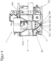
- FIG. 1 The Figures 2 and 3 show a perspective view of an end face of the coater arrangement FIG. 1 ,
- the first coater 3 may be fastened to the base plate 9 via a bearing block 11 at its free end facing away from the second coater 5.
- the coater 3 may, for example, be fastened to the base plate 7 via a further bearing block.
- the coater 3 may be pivotally mounted on the respective bearing block 11. This allows pivoting of the coater 3 about a horizontal pivot axis which runs parallel to the longitudinal axis of the coater 3 in order to adjust by means of a pivoting device 13 an angle of inclination of optional coater elements 15a and 15b attached to the coater 3.
- the pivoting device is exemplified here with a hydraulic drive 13a, which is arranged between bearing block and coater, and an electronically adjustable stop system 13b, which limits the pivot angle of the coater to the right and left variable.
- the two optional coating elements 15a and 15b are here exemplarily designed as coating strips and can be made for example of steel.
- the coating elements 15a and 15b may also be referred to as blades.
- the coating elements 15a and 15b form a downwardly directed coating surface that is substantially flat.
- the present coater 3 is exemplarily designed as a bidirectional coater which can coat in both directions, during a return journey and during a return journey, and can appropriately compact the spent particulate material.
- the described coater arrangement can also be configured as a unidirectional coater arrangement, in which case one of the blades can be saved.
- the coater arrangement can also be carried out without a pivotable coater and / or without an adjustable blade angle.
- the coater 3 may comprise, for example, a first, lower container 17, an (optional) second, upper container 19, and a support structure.
- the support structure may comprise, for example, one or more transversely to the direction of movement or in the coater longitudinally extending support 21a, 21b, which may be connected, for example along the coater longitudinal direction with a plurality of tubes or rods 21c in the transverse direction.
- the carriers 21a, 21b may, for example, be connected to a connecting plate 21e on at least one of their end faces.
- first and second containers 17, 19 may each have an elongate shape.
- the first container 17 has a shape tapering downwards in cross-section, for example a funnel shape. At its lower end, the first container 17 has a longitudinal slot (without reference numeral). At its upper end, the first container 17 may be open, for example, and with a lower, open one End of the second container communicate. For example, the first container 17 may be stiffened along the longitudinal direction with one or more stiffening elements 17c.
- the first container 17 can be designed as a vibrating container whose one side wall 17a (here the right side wall) can be acted upon by a vibrating device by a vibrating device 23 in order to vibrate particulate building material received in the container 17.
- the first container 17 is exemplarily connected on one side (here on the right side wall 17a) via the vibrator 23 to the support structure and connected on the other side (here on the left side wall 17b) via a damping device 25 with the support structure.
- the vibrating device 23 may, for example, comprise a shaft 23a, which is connected via an eccentric 23c to a connecting rod 23b, which is connected to the one side of the first container 17.
- a plurality of connecting rods 23b can be provided one behind the other. See for example FIG. 10 ,
- the damper device 25 may include, for example, a damper member 25b fixed to the support structure and a protrusion portion 25a connected to or formed by the other side of the first container 17 and supported on the damper member.
- a plurality of damping devices 25 may be provided one behind the other in the coater longitudinal direction, i. the first container may be connected to the support structure along the coater longitudinal direction at a plurality of locations.
- the (optional) second container 19 can exemplarily have a rectangular cross-sectional shape.
- the second container serves as a so-called storage container, which supplies the first container with building material.
- a distributor element 19a here a distributor screw, can be accommodated.
- the second container 19 may be rigidly connected to the support structure and / or be formed / limited by this.
- the first container and the second container are jogging motion decoupled from each other.
- the above-described shape / configuration and attachment of the first container and the formation of the first container as a vibrating container, the provision of a second container and the described support structure represent only optional features of the described coater arrangement.
- the second container can be saved and / or a carrier structure of a different design can be provided.
- the support structure may have, for example, along the coater longitudinal direction on both sides of the container 17, a plurality of ribs 21 d which are substantially rigidly connected to the supports 21 a and 21 b, respectively, and to which the coating elements 15 a and 15 b are attached, for example substantially rigid and shaking motion decoupled from the first container 17, for example using a respective ledge 29a or 29b, for example, attached to the rib via a respective intermediate part (not numbered).
- a first closing element 31a is arranged above the first coating element 15a and below the longitudinal slot, ie between the first coating element 15a and the first container 17, a first closing element 31a is arranged. This is exemplarily surrounded at the bottom by an upper side of the first coating element 15a, and is also surrounded on a lateral side by the strip 29a and at the top by the intermediate part (without the reference numeral). In a direction perpendicular to the longitudinal direction of the coater 3 and perpendicular to an imaginary vertical plane through the longitudinal slot, the first shutter 31a is exposed.
- a second closing element 31b is arranged above the second coating element 15b and below the longitudinal slot, ie between the second coating element 15b and the first container 17. This is exemplarily surrounded at the bottom by an upper side of the second coating element 15b, and is on a lateral side of the strip 29b and surrounded at the top by the intermediate part (without reference numeral). In a direction perpendicular to the longitudinal direction of the coater 3 and perpendicular to the imaginary vertical plane through the longitudinal slot, the second closing element 31 b is exposed.
- the respective closing element 31a, 31b can be fixedly connected to the associated coating element and / or the associated strip and / or the associated intermediate part, for example by gluing.
- the two closing elements 31a and 31b which are formed elongated, for example, together form a closing device 31 which is adapted to selectively close the opening of the container 17 for dispensing the particulate building material.
- the closing elements 31a and 31b are shown in their respective open state.
- closure members 31a and 31b may selectively partially obscure the opening in its respective closed state (for example, due to lateral expansion of the respective closure member) so that the closure members 31a and 31b together close the opening.
- the first closure member 31a and the second closure member 31b may include first and second hollow bodies, respectively, wherein each of the two hollow bodies has an interior cavity bounded by a deformable portion, with the two hollow bodies facing each other Sides of the opening are arranged such that the deformable portions face each other, wherein each of the two deformable portions is adapted to be deformed by a pressurized fluid supplied to the associated hollow body under an expansion of the inner cavity, so that the two deformable portion movable towards each other and be brought into contact with each other to thereby close the opening.
- the deformable sections may be formed, for example, by the above-described, lateral, free section of the respective closing element.
- a closing element formed in this way can, for example, also be referred to as an inflatable sealing element according to various embodiments.
- the closing device 31a and 31b instead of the two closing elements 31a and 31b, for example, only one closing element 31a can be provided which completely covers the opening in the closed state of the closing device.
- the closing device could for example comprise one or more slides.
- FIG. 1 for each of the coaters 3 and 5, a separate closing device may be shown so that the opening of a respective coater is independently and selectively closable.
- the coater whose construction job is completed first can be closed by means of its associated shutter, for example at least until the construction job of the other coater is completed.
- the coater assembly 1 has a coater 3 having a container 17 defining an internal cavity for receiving particulate building material opening in an opening for dispensing the particulate building material, and a closure device 31 adapted to dispose the opening for dispensing of the particulate building material to selectively close.
- the closure device 31 may include at least one closure member 31a, 31b attached to the coater 3 (exemplified herein by way of example) arranged to selectively conceal the opening at least partially Example as a result of lateral movement and / or deformation, such as a lateral expansion.
- the at least one closing element 31 a, 31 b may, for example, be arranged below the opening, for example at a vertical distance therefrom, and / or at least one (here exemplarily two) coating element 15a, 15b may be attached to the coater 3 adapted to pass over building material dispensed from the opening to thereby level and / or compact the dispensed particulate material, the at least one closure element 31a, 31b being located above the at least one coating element.
- the at least one closing element 31a, 31b, or at least the deformable portion thereof described below is here exemplarily made of a resilient, elastic silicone material and has a sealing surface which is adapted to seal in a closed state of the closing device on a counter surface.
- the sealing surface is formed on the deformable portion, which will be described below.
- the mating surface is also formed by a deformable portion.
- the first closing element 31a and the second closing element 31b may, for example, have a first and a second hollow body, respectively, wherein each of the two hollow bodies has an inner cavity 33 (see FIG. 9 ) which is delimited by a deformable portion 35, wherein the two hollow bodies are arranged on opposite sides of the opening (see FIG. 8a ), that the deformable portions face each other, and wherein each of the two hollow bodies is adapted to be deformed outwardly by a pressurized fluid supplied under an expansion of the inner cavity at the deformable portion so that the two deformable portions are movable towards each other and be brought into contact with each other to thereby close the opening (see FIG. 8b ).
- FIG. 8b it can be seen, while each of the two closing elements 31 a, 31 b partially covers the opening.
- the deformable portion 35 may, for example, be inwardly arched with the port open, and be bowed outwardly to close the port by a pressurized fluid supplied to the hollow body.
- the closure device 31 may further include a fluid line structure F (dashed line) through which the respective closure member 31a, 31b is in fluid communication with a source of pressurized fluid.
- a fluid line structure F dashed line
- the fluid line structure F may be formed, for example, at least in sections as a hose line structure, for example as a trailing hose line structure.
- the hose line structure may have a first and a second hose line Fa or Fb, wherein the respective hose line may, for example, be connected to the same at one end face of the associated closing element 31a, 31b.
- the source of pressurized fluid here has a compressed air tank P, which is designed as a stationary container by way of example here, and a valve V, which can be mounted, for example, between the compressed air tank P and the closing elements on the fluid line F.
- the closing device 31 may further include a control unit C configured to selectively close the opening by means of the at least one closing element 31 a, 31 b.
- control unit here exemplarily communicates with the valve V and is arranged to control this for closing the opening such that the pressure fluid source feeds pressurized fluid into the at least one hollow body 31a so that it is deformed at its deformable portion 35 thereby closing the opening.
- FIG. 8a the valve is closed (and consequently the closing device is opened), whereas in FIG. 8b the valve is open (and consequently the locking device is closed).
- an optional second coater may also be provided in this embodiment.
- This may for example have a separate closing device, which is controlled by the control unit analogous to the first closing device.
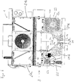
- FIG. 11 shows a 3D printer 100 according to an embodiment of the invention, wherein the plant housing is omitted, so that the plant frame 140 can be seen.
- the above-described coater apparatus 1 may be used in a 3D printer 100.
- Reference numeral 103 in this context shows a linear guide structure for the at least one coater 3.
- the 3D printer 100 may, for example, in addition to the coater arrangement 1 (here exemplifying having a first and a second coater 3, 5) a printing device having a print head 130 which is adapted to a to print predetermined portion of a previously applied layer of building material with treatment agent.
- the printhead 130 may, for example, be horizontally movable, for example, in a direction perpendicular to the direction in which the at least one coater 3, 5 is movable, for example along a first printhead unearger guide structure 131.
- the print head 130 can be set up, for example, to serve a plurality of construction fields (here two).
- the print head 130 may, for example, additionally be movable in the direction in which the at least one coater 3, 5 is movable, so that it can run off the building field or the entire meandering, for example in a U-shape.
- the print head 130 can be moved, for example, along a second print head linear guide structure 132.
- a respective building material layer may be selectively solidified, for example sintered, by a laser, for example (so-called “selective laser sintering").
- the 3D printer 100 may, for example, comprise one or more building areas B1 and B2 (here exemplifying two), for example from a respective build platform 112 (see FIG FIG. 12 ) and / or a respective building box 110 or 120, respectively, when it is in its construction position within the 3D printer.
- the respective building platform 112 can be height-adjustable, for example, with an associated lifting drive (here exemplarily with a lifting drive 114 fixed to the installation).
- an associated lifting drive here exemplarily with a lifting drive 114 fixed to the installation.
- the first building box 110 may be movable into and out of the 3D printer via a first roller track 116, and the second building box 120 may enter and exit the 3D printer via a second roller track 126, for example be movable.
- FIG. 12 shows the 3D printer 100 FIG. 11 This time with a large part of the plant housing 150 and with an integrated coater-loading unit 160.
- the 3D printer 100 may further include a coater feed unit 160 integrated into the 3D printer, with which build material can be prepared and fed into the coater (s).
- a coater feed unit 160 integrated into the 3D printer, with which build material can be prepared and fed into the coater (s).
- a part of the plant housing 150 and the first building box 100 is in FIG. 12 cut open to make the build platform 112 and the stack of building material layers arranged thereon visible.
- the coaters 3, 5 are in FIG. 12 moved backwards, and the print head 130 is right front.
- FIG. 12 it is easy to see how a first building area B1 or a second building area B2 is formed by the first building box and the second building box in the 3D printer.
- Reference numeral 170 denotes a common operating station.
- Reference numerals 116 and 126 designate a respective feeding device, here exemplarily in the form of a roller conveyor, with which a respective building box can be moved into its building box construction position within the 3D printer.
- FIGS. 13 and 14 show in plan view and perspective view from above a 3D printer assembly 200, which has a first and a second 3D printer 100 or 100 '.
- the two 3D printers can be like that with respect to the Figures 11 and 12 described 3D printer 100 may be formed.
- the first and second 3D printers 100, 100 ' may be disposed adjacent to each other such that the insertion openings for insertion of the building boxes face each other.
- a rail system 210 may extend between the two 3D printers, along which a common transport device 220 can be moved.
- the transport device 220 may be used by both the first and second 3D printers 100, 100 'to populate the respective 3D printer with one or more building boxes.
- one or more optional components may be arranged along the rail system, for example a building box stock 230 in which one or more building boxes are provided, and / or a microwave oven 240 capable of housing a building box around a component contained therein (Further) cure, and / or an unpacking 250, where a component contained in the Baubox freed from loose, not solidified particulate material and thus "unpacked", for example, automated.
- the reference numeral 260 designates an optional component supply into which unwrapped components (here by way of example casting molds and / or casting cores) that have been produced by means of a generative manufacturing method using one of the two 3D printers can be stored.
- a first construction job and simultaneously, ie temporally overlapping, in one a second construction job is performed, wherein the first construction area is served by a first coater and the second construction area by a second coater, wherein the first and the second coater are moved together across the first and second building area, for example; wherein when the first construction job is completed, a discharge port for discharging building material of first coater is closed by means of a closing device.
- the first construction job can be less time-consuming than the second construction job.
- a coater of a 3D printer in a coater cleaning process - for example using a 3D printer constructed as described above and / or using a coater arrangement formed as described above - can be moved to a cleaning station to the coater to clean, wherein a discharge opening of the coater during cleaning of the coater, for example by a coating element thereof, at least temporarily closed by means of a closure device attached to the coater.
- the 3D printer can have, for example, an integrated cleaning station in which the coater, for example the at least one coating element of the same, can be brushed off.
- the 3D printer may be formed as described above, for example.
Landscapes
- Engineering & Computer Science (AREA)
- Chemical & Material Sciences (AREA)
- Materials Engineering (AREA)
- Manufacturing & Machinery (AREA)
- Mechanical Engineering (AREA)
- Physics & Mathematics (AREA)
- Optics & Photonics (AREA)
- Robotics (AREA)
- Coating Apparatus (AREA)
Claims (15)
- Dispositif de revêtement (1) pour une imprimante 3D (100) comprenant :une coucheuse (3) avec un récipient (17), qui présente une forme allongée et qui définit un espace creux interne pour le logement d'un matériau de construction particulaire, qui débouche dans une ouverture pour la distribution du matériau de construction particulaire, qui présente la forme d'une fente longitudinale etun dispositif de fermeture (31) qui est conçu pour fermer sélectivement l'ouverture de distribution du matériau de construction particulaire,le dispositif de fermeture (31) comprenant au moins un élément de fermeture (31 a), monté sur la coucheuse (3), qui présente une forme allongée et qui est conçu pour recouvrir sélectivement l'ouverture au partiellement à la suite d'un déplacement et/ou d'une déformation latérale,caractérisé en ce que
l'au moins un élément de fermeture (31 a) est constitué d'un corps creux dont l'espace creux interne (33) est limité par une portion déformable (35), le corps creux étant conçu pour être déformé vers l'extérieur, au niveau de la portion déformable, par un fluide sous pression introduit dans le corps creux, qui provoque la dilatation de l'espace creux interne, afin de recouvrir au moins partiellement l'ouverture. - Dispositif de revêtement (1) selon la revendication 1,
la coucheuse (3) étant mobile dans la direction horizontale et l'axe longitudinal du récipient (17) et/ou l'axe longitudinal de la fente longitudinale s'étendent dans une direction horizontale, qui est mobile perpendiculairement à la direction dans laquelle la coucheuse (3) est mobile et/ou
l'axe longitudinal de l'au moins un élément de fermeture (31a) s'étend globalement parallèlement à l'extension longitudinale de la fente et l'au moins un élément de fermeture (31 a) étant mobile et/ou déformable et/ou dilatable perpendiculairement à son axe longitudinal. - Dispositif de revêtement (1) selon la revendication 1 ou 2, l'au moins un élément de fermeture (31 a) étant disposé en dessous de l'ouverture.
- Dispositif de revêtement (1) selon l'une des revendications 1 à 3,
la coucheuse (3) comprenant en outre au moins un élément de badigeonnage (15a) qui est conçu pour badigeonner le matériau de construction distribué par l'ouverture, afin de niveler et/ou de comprimer ainsi le matériau particulaire distribué et
l'au moins un élément de fermeture (31a) étant disposé au-dessus de l'au moins un élément de badigeonnage. - Dispositif de revêtement (1) selon l'une des revendications 1 à 4, l'au moins un élément de fermeture (31a) présentant une surface d'étanchéité qui est conçue pour étanchéifier, dans un état de fermeture du dispositif de fermeture contre une contre-surface et la surface d'étanchéité étant constituée d'un matériau flexible.
- Dispositif de revêtement (1) selon l'une des revendications 1 à 5, le dispositif de fermeture (31) comprenant un premier et un deuxième corps creux (31 a, 31 b), chacun des deux corps creux comprenant un espace creux interne (33), qui est délimité par une portion déformable (35), les deux corps creux étant disposés sur des côtés opposés de l'ouverture de façon à ce que les portions déformables soient orientées l'une vers l'autre et chacun des deux corps creux étant conçu pour être déformé vers l'extérieur par un fluide sous pression introduit, sous l'effet d'une dilatation de l'espace creux interne au niveau de la portion déformable, de façon à ce que les deux portions déformables soient mobiles l'une vers l'autre et puissent être mises en contact entre elles afin de fermer l'ouverture.
- Dispositif de revêtement (1) selon l'une des revendications 1 à 6, la portion déformable (35) étant incurvée vers l'intérieur lorsque l'ouverture est dégagée et pouvant être incurvée vers l'extérieur, pour la fermeture de l'ouverture, par un fluide sous pression introduit dans le corps creux.
- Dispositif de revêtement (1) selon l'une des revendications 1 à 7, le dispositif de fermeture (31) comprenant en outre :une structure de conduite de fluide (F) par l'intermédiaire de laquelle le corps creux (31 a) correspondant est reliée de manière fluidique avec une source de fluide sous pression (P, V).
- Dispositif de revêtement (1) selon l'une des revendications 1 à 8, le dispositif de fermeture (31) comprenant en outre :une unité de commande (C), qui est conçue pour fermer sélectivement, de manière contrôlée, l'ouverture au moyen de l'au moins un élément de fermeture (31 a),en option, l'unité de commande (C) étant relié avec la source de fluide sous pression (P, V) selon la revendication 8 et étant conçu pour contrôler celle-ci pour une fermeture de l'ouverture de façon à ce que la source de fluide sous pression introduise du fluide sous pression dans le corps creux (31 a), de façon à ce que celui-ci soit déformé au niveau de sa portion déformable (35).
- Dispositif de revêtement (1) selon l'une des revendications précédentes, avec une pluralité de coucheuses (3, 5) et un nombre correspondant de dispositifs de fermeture, de façon à ce que l'ouverture d'une coucheuse correspondante puisse être fermée indépendamment et de manière sélective, les coucheuses (3, 5) étant, en option, mobiles ensemble sur un champ de construction correspondant.
- Dispositif de revêtement (1) selon l'une des revendications précédentes, comprenant en outre une unité de commande (C), par exemple l'unité de commande selon la revendication 9 ou 10, qui est conçu pour
fermer le dispositif de fermeture (31) lorsque la tâche de construction allouée à la coucheuse (3) est terminée et/ou interrompue et/ou
fermer, par les coucheuses (3, 5) selon la revendication 10, l'ouverture de la coucheuse, dont la tâche de construction est terminée en premier, au moyen de son dispositif de fermeture correspondant et/ou
pendant un trajet sans revêtement, par exemple un trajet en marche arrière sans revêtement d'une coucheuse unidirectionnelle, fermer le dispositif de fermeture (31) de la coucheuse (3) et/ou
pendant une partie de trajet sans revêtement, par exemple une partie de trajet de pré-traitement et/ou de post-traitement d'une coucheuse unidirectionnelle, fermer le dispositif de fermeture (31) de la coucheuse (3) et/ou
dans une position de repos de la coucheuse (3), fermer le dispositif de fermeture (31) de la coucheuse et/ou
fermer le dispositif de fermeture (31) de la coucheuse (3) pour un nettoyage de la coucheuse. - Imprimante 3D (100), comprenant un dispositif de revêtement (1) selon l'une des revendications précédentes.
- Procédé de fabrication additive, dans lequel, dans une première zone de construction (B1), une première tâche de construction est effectuée et simultanément, dans une deuxième zone de construction (B2), une deuxième tâche de construction est effectuée, la première zone de construction étant desservie par une première coucheuse (3) et la deuxième zone de construction étant desservie par une deuxième coucheuse (5), la première et la deuxième coucheuses étant déplacée ensemble au-dessus de la première ou de la deuxième zone de construction, moyennant quoi, lorsque la première tâche de construction est terminée, une ouverture de distribution de matériau de construction de la première coucheuse étant fermée au moyen d'un dispositif de fermeture (31) selon l'une des revendications 1 à 11, la première tâche de construction nécessitant moins de temps que la deuxième tâche de construction et la deuxième tâche de construction étant continuée après la fin de la première tâche de construction et, pendant ce temps, la première coucheuse est déplacée plus loin au-dessus de sa zone de construction correspondante, ensemble avec la deuxième coucheuse, mais sans distribuer de matériau de construction.
- Procédé de fabrication additive,
dans lequel une coucheuse (3) est déplacée au-dessus d'une zone de construction (B1) correspondante afin de distribuer un matériau de construction particulaire sous la forme d'une couche uniforme sur la zone de construction,
une ouverture de distribution de la coucheuse étant ferméependant un trajet sans revêtement, par exemple un trajet en marche arrière sans revêtement d'une coucheuse unidirectionnelle et/oupendant une partie de trajet sans revêtement, par exemple une partie de trajet de pré-traitement et/ou de post-traitement et/oudans une position de repos de la coucheuse et/ouà la fin et/ou après la fin et/ou lors d'une interruption d'une tâche de construction et/ou pour un nettoyage de la coucheuseau moins temporairement au moyen d'un dispositif de fermeture (31), monté sur la coucheuse, selon l'une des revendications 1 à 11. - Procédé de nettoyage de coucheuse, dans lequel une coucheuse (3) d'une imprimante 3D est déplacée vers une station de nettoyage afin de nettoyer la coucheuse, une ouverture de distribution de la coucheuse étant fermée au moins temporairement au moyen d'un dispositif de fermeture (31), selon l'une des revendications 1 à 11, monté sur la coucheuse, pendant un nettoyage de la coucheuse, par exemple d'un élément de badigeonnage de celle-ci.
Applications Claiming Priority (2)
| Application Number | Priority Date | Filing Date | Title |
|---|---|---|---|
| DE102014112454.5A DE102014112454A1 (de) | 2014-08-29 | 2014-08-29 | Beschichteranordnung für einen 3D-Drucker |
| PCT/EP2015/069470 WO2016030391A1 (fr) | 2014-08-29 | 2015-08-25 | Système de revêtement pour imprimante 3d |
Publications (2)
| Publication Number | Publication Date |
|---|---|
| EP3036087A1 EP3036087A1 (fr) | 2016-06-29 |
| EP3036087B1 true EP3036087B1 (fr) | 2016-12-21 |
Family
ID=54147138
Family Applications (1)
| Application Number | Title | Priority Date | Filing Date |
|---|---|---|---|
| EP15766065.5A Active EP3036087B1 (fr) | 2014-08-29 | 2015-08-25 | Système de revêtement pour imprimante 3d |
Country Status (6)
| Country | Link |
|---|---|
| US (1) | US11524454B2 (fr) |
| EP (1) | EP3036087B1 (fr) |
| JP (1) | JP6188109B1 (fr) |
| CN (1) | CN106457615B (fr) |
| DE (1) | DE102014112454A1 (fr) |
| WO (1) | WO2016030391A1 (fr) |
Cited By (1)
| Publication number | Priority date | Publication date | Assignee | Title |
|---|---|---|---|---|
| WO2019141762A1 (fr) | 2018-01-18 | 2019-07-25 | Eos Gmbh Electro Optical Systems | Dispositif de dosage, dispositif et procédé de fabrication additive d'un objet tridimensionnel |
Families Citing this family (17)
| Publication number | Priority date | Publication date | Assignee | Title |
|---|---|---|---|---|
| DE102014112469A1 (de) * | 2014-08-29 | 2016-03-03 | Exone Gmbh | Beschichteranordnung für einen 3d-drucker |
| US20170368816A1 (en) * | 2014-12-23 | 2017-12-28 | Stratasys, Inc. | Resin slot extruder for additive manufacturing system |
| DE102015103726A1 (de) | 2015-03-13 | 2016-09-15 | Exone Gmbh | 3D-Drucker mit Beschichter und Beschichter-Reinigungsvorrichtung |
| DE102015003372A1 (de) * | 2015-03-17 | 2016-09-22 | Voxeljet Ag | Verfahren und Vorrichtung zum Herstellen von 3D-Formteilen mit Doppelrecoater |
| DE102015217143A1 (de) * | 2015-09-08 | 2017-03-09 | Siemens Aktiengesellschaft | Durchführung, Düse und 3D-Drucker |
| CN105643941A (zh) * | 2016-03-07 | 2016-06-08 | 宁夏共享模具有限公司 | 一种3d打印设备的铺料装置 |
| DE102017120205A1 (de) | 2017-09-01 | 2019-03-07 | Exone Gmbh | Beschichteranordnung für einen 3d-drucker |
| EP3466687A1 (fr) | 2017-10-04 | 2019-04-10 | CL Schutzrechtsverwaltungs GmbH | Dispositif de module de poudre pour un appareil de fabrication additive d'objets tridimensionnels |
| DE102018102753A1 (de) | 2018-02-07 | 2019-08-08 | Exone Gmbh | 3d-drucker und generatives fertigungsverfahren |
| CN109051889B (zh) * | 2018-08-29 | 2024-10-11 | 共享智能装备有限公司 | 增材制造设备用铺料装置 |
| CN110497614B (zh) * | 2019-02-21 | 2024-05-10 | 广州捷和电子科技有限公司 | 一种用于3d打印设备的淋涂喷头及相应的打印方法 |
| CN109910297A (zh) * | 2019-02-27 | 2019-06-21 | 共享智能铸造产业创新中心有限公司 | 一种多材料复合的3d打印设备及其打印方法 |
| WO2020237142A1 (fr) * | 2019-05-23 | 2020-11-26 | General Electric Company | Ensembles de recouvrement de fabrication additive comprenant un vide et leurs procédés d'utilisation |
| DE102019208440A1 (de) * | 2019-06-11 | 2020-12-17 | Aim3D Gmbh | Fertigungsstraße und 3D-Druckvorrichtung |
| DE102019004342A1 (de) * | 2019-06-23 | 2020-12-24 | Voxeljet Ag | Anordnung einer 3D-Druckvorrichtung |
| DE102019007480A1 (de) * | 2019-10-26 | 2021-04-29 | Laempe Mössner Sinto Gmbh | Anordnung und Verfahren zum Erzeugen einer Schicht eines partikelförmigen Baumaterials in einem 3D-Drucker |
| CN114770940B (zh) * | 2022-04-28 | 2022-11-25 | 深圳市智能派科技有限公司 | 一种3d打印刮刀机构及打印机 |
Family Cites Families (31)
| Publication number | Priority date | Publication date | Assignee | Title |
|---|---|---|---|---|
| US1095767A (en) * | 1913-03-29 | 1914-05-05 | George Cooke Adams | Throttling device for pipes or tubes or pumps. |
| US2598207A (en) * | 1946-06-14 | 1952-05-27 | Bailey Meter Co | Valving apparatus |
| US2874925A (en) * | 1954-09-17 | 1959-02-24 | Fmc Corp | Valve for fluids or fluidized solids especially for the spouts of bag filling apparatus |
| DE1252022B (fr) * | 1963-03-01 | 1967-10-12 | ||
| FR2285558A1 (fr) * | 1974-09-20 | 1976-04-16 | Swinnen Richard | Vanne-ecluse a commande pneumatique |
| US4496132A (en) * | 1981-08-27 | 1985-01-29 | Zvi Weingarten | Sleeve valve with integral control chamber |
| DE3519651A1 (de) * | 1985-06-01 | 1986-12-04 | Klöckner-Humboldt-Deutz AG, 5000 Köln | Druckschleuse |
| DE4400523C2 (de) * | 1994-01-11 | 1996-07-11 | Eos Electro Optical Syst | Verfahren und Vorrichtung zum Herstellen eines dreidimensionalen Objekts |
| FR2720338B1 (fr) * | 1994-05-26 | 1996-06-21 | Gec Alsthom Transport Sa | Dispositif d'obturation d'une gaine de distribution et installation comportant un tel dispositif. |
| DE19649865C1 (de) * | 1996-12-02 | 1998-02-12 | Fraunhofer Ges Forschung | Verfahren zur Herstellung eines Formkörpers |
| DE19723892C1 (de) * | 1997-06-06 | 1998-09-03 | Rainer Hoechsmann | Verfahren zum Herstellen von Bauteilen durch Auftragstechnik |
| FR2790418B1 (fr) * | 1999-03-01 | 2001-05-11 | Optoform Sarl Procedes De Prot | Procede de prototypage rapide permettant l'utilisation de materiaux pateux, et dispositif pour sa mise en oeuvre |
| EP1234625A1 (fr) * | 2001-02-21 | 2002-08-28 | Trumpf Werkzeugmaschinen GmbH + Co. KG | Procédé et dispositif pour fabriquer un article par frittage selective au laser |
| DE10117875C1 (de) * | 2001-04-10 | 2003-01-30 | Generis Gmbh | Verfahren, Vorrichtung zum Auftragen von Fluiden sowie Verwendung einer solchen Vorrichtung |
| US6656410B2 (en) * | 2001-06-22 | 2003-12-02 | 3D Systems, Inc. | Recoating system for using high viscosity build materials in solid freeform fabrication |
| DE10216013B4 (de) * | 2002-04-11 | 2006-12-28 | Generis Gmbh | Verfahren und Vorrichtung zum Auftragen von Fluiden |
| DE10235427A1 (de) | 2002-08-02 | 2004-02-12 | Eos Gmbh Electro Optical Systems | Vorrichtung und Verfahren zum Herstellen von dreidimensionalen Objekten mittels eines generativen Fertigungsverfahrens |
| DE102005006522B3 (de) * | 2005-02-11 | 2006-08-03 | J. Wagner Ag | Vorrichtung zum Fördern von Beschichtungspulver und Verfahren zum Fördern von Pulver mit der Fördervorrichtung |
| DE102005056260B4 (de) * | 2005-11-25 | 2008-12-18 | Prometal Rct Gmbh | Verfahren und Vorrichtung zum flächigen Auftragen von fließfähigem Material |
| DE102006023485A1 (de) * | 2006-05-18 | 2007-11-22 | Eos Gmbh Electro Optical Systems | Vorrichtung und Verfahren zum Herstellen eines dreidimensionalen Objekts |
| DE102006023484A1 (de) * | 2006-05-18 | 2007-11-22 | Eos Gmbh Electro Optical Systems | Vorrichtung und Verfahren zum schichtweisen Herstellen eines dreidimensionalen Objekts aus einem pulverförmigen Aufbaumaterial |
| DE202006010327U1 (de) * | 2006-07-04 | 2007-11-15 | Prometal Rct Gmbh | Wechselbehälter |
| DE102009056689B4 (de) | 2009-12-02 | 2015-10-15 | Prometal Rct Gmbh | Beschichter für eine Rapid-Prototyping-Anlage |
| DE202009018948U1 (de) | 2009-12-02 | 2014-10-10 | Exone Gmbh | Anlage zum schichtweisen Aufbau eines Formkörpers mit einer Beschichter-Reinigungsvorrichtung |
| DE102009056696B4 (de) | 2009-12-02 | 2011-11-10 | Prometal Rct Gmbh | Baubox für eine Rapid-Prototyping-Anlage |
| GB2482010B (en) * | 2010-07-14 | 2012-06-27 | Upcycle Holdings Ltd | Applicator device for plastic moulding machine |
| JP2014000768A (ja) * | 2012-06-20 | 2014-01-09 | Brother Ind Ltd | 立体造形装置 |
| CN202967555U (zh) * | 2012-11-09 | 2013-06-05 | 裕东(中山)机械工程有限公司 | 一种粉末输送装置 |
| DE102014112450A1 (de) * | 2014-08-29 | 2016-03-03 | Exone Gmbh | Beschichteranordnung für einen 3D-Drucker |
| DE102014112447A1 (de) * | 2014-08-29 | 2016-03-03 | Exone Gmbh | 3D-Drucker, 3D-Druckeranordnung und generatives Fertigungsverfahren |
| DE102014112469A1 (de) * | 2014-08-29 | 2016-03-03 | Exone Gmbh | Beschichteranordnung für einen 3d-drucker |
-
2014
- 2014-08-29 DE DE102014112454.5A patent/DE102014112454A1/de not_active Ceased
-
2015
- 2015-08-25 JP JP2016569788A patent/JP6188109B1/ja active Active
- 2015-08-25 CN CN201580028682.XA patent/CN106457615B/zh active Active
- 2015-08-25 EP EP15766065.5A patent/EP3036087B1/fr active Active
- 2015-08-25 US US15/506,779 patent/US11524454B2/en active Active
- 2015-08-25 WO PCT/EP2015/069470 patent/WO2016030391A1/fr active Application Filing
Cited By (1)
| Publication number | Priority date | Publication date | Assignee | Title |
|---|---|---|---|---|
| WO2019141762A1 (fr) | 2018-01-18 | 2019-07-25 | Eos Gmbh Electro Optical Systems | Dispositif de dosage, dispositif et procédé de fabrication additive d'un objet tridimensionnel |
Also Published As
| Publication number | Publication date |
|---|---|
| US11524454B2 (en) | 2022-12-13 |
| CN106457615A (zh) | 2017-02-22 |
| WO2016030391A1 (fr) | 2016-03-03 |
| DE102014112454A1 (de) | 2016-03-03 |
| US20170341303A1 (en) | 2017-11-30 |
| EP3036087A1 (fr) | 2016-06-29 |
| JP6188109B1 (ja) | 2017-08-30 |
| JP2017527454A (ja) | 2017-09-21 |
| CN106457615B (zh) | 2019-08-23 |
Similar Documents
| Publication | Publication Date | Title |
|---|---|---|
| EP3036087B1 (fr) | Système de revêtement pour imprimante 3d | |
| EP3030403B1 (fr) | Système de revêtement pour imprimante 3d | |
| EP3043980B1 (fr) | Système de revêtement pour imprimante 3d et procédé d'application de deux couches à partir d'un matériau de construction de particules | |
| EP3351384B1 (fr) | Imprimante tridimensionnelle, système d'imprimante tridimensionnelle et procédé de fabrication générative | |
| EP2661354B1 (fr) | Procédé de construction d'un corps stratifié qui comporte au moins un corps délimitant la zone de construction et dont la position peut être réglée | |
| EP1872928B1 (fr) | Procédé de production d'objets tridimensionnels | |
| EP2507037B1 (fr) | Installation de fabrication d'un prototype par dépôt de couches comportant un ensemble de nettoyage de dispositif de dépôt de couches | |
| DE102009056696B4 (de) | Baubox für eine Rapid-Prototyping-Anlage | |
| EP2389285B1 (fr) | Trémie pour une installation de prototypage rapide | |
| EP3638488B1 (fr) | Système de revêtement pour imprimante 3d | |
| EP2864107A1 (fr) | Dispositif de fabrication d'un corps stratifié comprenant un réservoir de stockage ou de remplissage mobile le long du réservoir de distribution | |
| DE102006041320A1 (de) | Beschichtereinrichtung für eine Bauvorrichtung zur Erstellung von Formteilen aus pulverartigem Baumaterial unter Einbringung von Strahlungsenergie | |
| WO2016146289A1 (fr) | Imprimante 3d équipée d'un dispositif de dépôt et d'un dispositif de nettoyage de dispositif de dépôt et procédé de nettoyage d'un dispositif de dépôt d'une imprimante 3d | |
| DE102009056688A1 (de) | Rapid-Prototyping-Anlage mit einer Mischeinheit | |
| EP2389286B1 (fr) | Délimitation de zone de construction d'une installation de prototypage rapide | |
| EP3705267B1 (fr) | Module de coucheuse / tête d'impression pour une imprimante tridimensionnelle, utilisation du module de coucheuse / tête d'impression et imprimante tridimensionnelle pourvu de module de coucheuse / tête d'impression | |
| DE102009056694A1 (de) | Druckvorrichtung für eine Rapid-Prototyping-Anlage | |
| DE102014010951A1 (de) | Verfahren und Vorrichtung zum Dosieren von formlosem Baumaterial in einem Schichtbauverfahren | |
| DE102022126586A1 (de) | 3D-Druck-Verfahren und 3D-Drucker |
Legal Events
| Date | Code | Title | Description |
|---|---|---|---|
| PUAI | Public reference made under article 153(3) epc to a published international application that has entered the european phase |
Free format text: ORIGINAL CODE: 0009012 |
|
| 17P | Request for examination filed |
Effective date: 20160203 |
|
| AK | Designated contracting states |
Kind code of ref document: A1 Designated state(s): AL AT BE BG CH CY CZ DE DK EE ES FI FR GB GR HR HU IE IS IT LI LT LU LV MC MK MT NL NO PL PT RO RS SE SI SK SM TR |
|
| AX | Request for extension of the european patent |
Extension state: BA ME |
|
| GRAP | Despatch of communication of intention to grant a patent |
Free format text: ORIGINAL CODE: EPIDOSNIGR1 |
|
| DAV | Request for validation of the european patent (deleted) | ||
| DAX | Request for extension of the european patent (deleted) | ||
| INTG | Intention to grant announced |
Effective date: 20160708 |
|
| GRAS | Grant fee paid |
Free format text: ORIGINAL CODE: EPIDOSNIGR3 |
|
| GRAA | (expected) grant |
Free format text: ORIGINAL CODE: 0009210 |
|
| AK | Designated contracting states |
Kind code of ref document: B1 Designated state(s): AL AT BE BG CH CY CZ DE DK EE ES FI FR GB GR HR HU IE IS IT LI LT LU LV MC MK MT NL NO PL PT RO RS SE SI SK SM TR |
|
| REG | Reference to a national code |
Ref country code: GB Ref legal event code: FG4D Free format text: NOT ENGLISH |
|
| REG | Reference to a national code |
Ref country code: CH Ref legal event code: EP |
|
| REG | Reference to a national code |
Ref country code: IE Ref legal event code: FG4D Free format text: LANGUAGE OF EP DOCUMENT: GERMAN |
|
| REG | Reference to a national code |
Ref country code: AT Ref legal event code: REF Ref document number: 855104 Country of ref document: AT Kind code of ref document: T Effective date: 20170115 |
|
| REG | Reference to a national code |
Ref country code: DE Ref legal event code: R096 Ref document number: 502015000418 Country of ref document: DE |
|
| PG25 | Lapsed in a contracting state [announced via postgrant information from national office to epo] |
Ref country code: LV Free format text: LAPSE BECAUSE OF FAILURE TO SUBMIT A TRANSLATION OF THE DESCRIPTION OR TO PAY THE FEE WITHIN THE PRESCRIBED TIME-LIMIT Effective date: 20161221 |
|
| REG | Reference to a national code |
Ref country code: NL Ref legal event code: FP |
|
| REG | Reference to a national code |
Ref country code: LT Ref legal event code: MG4D |
|
| PG25 | Lapsed in a contracting state [announced via postgrant information from national office to epo] |
Ref country code: LT Free format text: LAPSE BECAUSE OF FAILURE TO SUBMIT A TRANSLATION OF THE DESCRIPTION OR TO PAY THE FEE WITHIN THE PRESCRIBED TIME-LIMIT Effective date: 20161221 Ref country code: SE Free format text: LAPSE BECAUSE OF FAILURE TO SUBMIT A TRANSLATION OF THE DESCRIPTION OR TO PAY THE FEE WITHIN THE PRESCRIBED TIME-LIMIT Effective date: 20161221 Ref country code: NO Free format text: LAPSE BECAUSE OF FAILURE TO SUBMIT A TRANSLATION OF THE DESCRIPTION OR TO PAY THE FEE WITHIN THE PRESCRIBED TIME-LIMIT Effective date: 20170321 Ref country code: GR Free format text: LAPSE BECAUSE OF FAILURE TO SUBMIT A TRANSLATION OF THE DESCRIPTION OR TO PAY THE FEE WITHIN THE PRESCRIBED TIME-LIMIT Effective date: 20170322 |
|
| PG25 | Lapsed in a contracting state [announced via postgrant information from national office to epo] |
Ref country code: RS Free format text: LAPSE BECAUSE OF FAILURE TO SUBMIT A TRANSLATION OF THE DESCRIPTION OR TO PAY THE FEE WITHIN THE PRESCRIBED TIME-LIMIT Effective date: 20161221 Ref country code: FI Free format text: LAPSE BECAUSE OF FAILURE TO SUBMIT A TRANSLATION OF THE DESCRIPTION OR TO PAY THE FEE WITHIN THE PRESCRIBED TIME-LIMIT Effective date: 20161221 Ref country code: HR Free format text: LAPSE BECAUSE OF FAILURE TO SUBMIT A TRANSLATION OF THE DESCRIPTION OR TO PAY THE FEE WITHIN THE PRESCRIBED TIME-LIMIT Effective date: 20161221 |
|
| PG25 | Lapsed in a contracting state [announced via postgrant information from national office to epo] |
Ref country code: SK Free format text: LAPSE BECAUSE OF FAILURE TO SUBMIT A TRANSLATION OF THE DESCRIPTION OR TO PAY THE FEE WITHIN THE PRESCRIBED TIME-LIMIT Effective date: 20161221 Ref country code: EE Free format text: LAPSE BECAUSE OF FAILURE TO SUBMIT A TRANSLATION OF THE DESCRIPTION OR TO PAY THE FEE WITHIN THE PRESCRIBED TIME-LIMIT Effective date: 20161221 Ref country code: RO Free format text: LAPSE BECAUSE OF FAILURE TO SUBMIT A TRANSLATION OF THE DESCRIPTION OR TO PAY THE FEE WITHIN THE PRESCRIBED TIME-LIMIT Effective date: 20161221 Ref country code: IS Free format text: LAPSE BECAUSE OF FAILURE TO SUBMIT A TRANSLATION OF THE DESCRIPTION OR TO PAY THE FEE WITHIN THE PRESCRIBED TIME-LIMIT Effective date: 20170421 Ref country code: CZ Free format text: LAPSE BECAUSE OF FAILURE TO SUBMIT A TRANSLATION OF THE DESCRIPTION OR TO PAY THE FEE WITHIN THE PRESCRIBED TIME-LIMIT Effective date: 20161221 |
|
| REG | Reference to a national code |
Ref country code: FR Ref legal event code: PLFP Year of fee payment: 3 |
|
| PG25 | Lapsed in a contracting state [announced via postgrant information from national office to epo] |
Ref country code: PL Free format text: LAPSE BECAUSE OF FAILURE TO SUBMIT A TRANSLATION OF THE DESCRIPTION OR TO PAY THE FEE WITHIN THE PRESCRIBED TIME-LIMIT Effective date: 20161221 Ref country code: PT Free format text: LAPSE BECAUSE OF FAILURE TO SUBMIT A TRANSLATION OF THE DESCRIPTION OR TO PAY THE FEE WITHIN THE PRESCRIBED TIME-LIMIT Effective date: 20170421 Ref country code: BG Free format text: LAPSE BECAUSE OF FAILURE TO SUBMIT A TRANSLATION OF THE DESCRIPTION OR TO PAY THE FEE WITHIN THE PRESCRIBED TIME-LIMIT Effective date: 20170321 Ref country code: SM Free format text: LAPSE BECAUSE OF FAILURE TO SUBMIT A TRANSLATION OF THE DESCRIPTION OR TO PAY THE FEE WITHIN THE PRESCRIBED TIME-LIMIT Effective date: 20161221 Ref country code: ES Free format text: LAPSE BECAUSE OF FAILURE TO SUBMIT A TRANSLATION OF THE DESCRIPTION OR TO PAY THE FEE WITHIN THE PRESCRIBED TIME-LIMIT Effective date: 20161221 |
|
| REG | Reference to a national code |
Ref country code: DE Ref legal event code: R097 Ref document number: 502015000418 Country of ref document: DE |
|
| PLBE | No opposition filed within time limit |
Free format text: ORIGINAL CODE: 0009261 |
|
| STAA | Information on the status of an ep patent application or granted ep patent |
Free format text: STATUS: NO OPPOSITION FILED WITHIN TIME LIMIT |
|
| 26N | No opposition filed |
Effective date: 20170922 |
|
| PG25 | Lapsed in a contracting state [announced via postgrant information from national office to epo] |
Ref country code: DK Free format text: LAPSE BECAUSE OF FAILURE TO SUBMIT A TRANSLATION OF THE DESCRIPTION OR TO PAY THE FEE WITHIN THE PRESCRIBED TIME-LIMIT Effective date: 20161221 |
|
| PG25 | Lapsed in a contracting state [announced via postgrant information from national office to epo] |
Ref country code: SI Free format text: LAPSE BECAUSE OF FAILURE TO SUBMIT A TRANSLATION OF THE DESCRIPTION OR TO PAY THE FEE WITHIN THE PRESCRIBED TIME-LIMIT Effective date: 20161221 |
|
| PG25 | Lapsed in a contracting state [announced via postgrant information from national office to epo] |
Ref country code: MC Free format text: LAPSE BECAUSE OF FAILURE TO SUBMIT A TRANSLATION OF THE DESCRIPTION OR TO PAY THE FEE WITHIN THE PRESCRIBED TIME-LIMIT Effective date: 20161221 |
|
| REG | Reference to a national code |
Ref country code: BE Ref legal event code: MM Effective date: 20170831 |
|
| REG | Reference to a national code |
Ref country code: IE Ref legal event code: MM4A |
|
| PG25 | Lapsed in a contracting state [announced via postgrant information from national office to epo] |
Ref country code: LU Free format text: LAPSE BECAUSE OF NON-PAYMENT OF DUE FEES Effective date: 20170825 |
|
| PG25 | Lapsed in a contracting state [announced via postgrant information from national office to epo] |
Ref country code: IE Free format text: LAPSE BECAUSE OF NON-PAYMENT OF DUE FEES Effective date: 20170825 |
|
| REG | Reference to a national code |
Ref country code: FR Ref legal event code: PLFP Year of fee payment: 4 |
|
| PG25 | Lapsed in a contracting state [announced via postgrant information from national office to epo] |
Ref country code: BE Free format text: LAPSE BECAUSE OF NON-PAYMENT OF DUE FEES Effective date: 20170831 |
|
| PG25 | Lapsed in a contracting state [announced via postgrant information from national office to epo] |
Ref country code: MT Free format text: LAPSE BECAUSE OF FAILURE TO SUBMIT A TRANSLATION OF THE DESCRIPTION OR TO PAY THE FEE WITHIN THE PRESCRIBED TIME-LIMIT Effective date: 20161221 |
|
| REG | Reference to a national code |
Ref country code: CH Ref legal event code: PL |
|
| PG25 | Lapsed in a contracting state [announced via postgrant information from national office to epo] |
Ref country code: LI Free format text: LAPSE BECAUSE OF NON-PAYMENT OF DUE FEES Effective date: 20180831 Ref country code: CH Free format text: LAPSE BECAUSE OF NON-PAYMENT OF DUE FEES Effective date: 20180831 |
|
| PG25 | Lapsed in a contracting state [announced via postgrant information from national office to epo] |
Ref country code: HU Free format text: LAPSE BECAUSE OF FAILURE TO SUBMIT A TRANSLATION OF THE DESCRIPTION OR TO PAY THE FEE WITHIN THE PRESCRIBED TIME-LIMIT; INVALID AB INITIO Effective date: 20150825 |
|
| PG25 | Lapsed in a contracting state [announced via postgrant information from national office to epo] |
Ref country code: CY Free format text: LAPSE BECAUSE OF FAILURE TO SUBMIT A TRANSLATION OF THE DESCRIPTION OR TO PAY THE FEE WITHIN THE PRESCRIBED TIME-LIMIT Effective date: 20161221 |
|
| PG25 | Lapsed in a contracting state [announced via postgrant information from national office to epo] |
Ref country code: MK Free format text: LAPSE BECAUSE OF FAILURE TO SUBMIT A TRANSLATION OF THE DESCRIPTION OR TO PAY THE FEE WITHIN THE PRESCRIBED TIME-LIMIT Effective date: 20161221 |
|
| PG25 | Lapsed in a contracting state [announced via postgrant information from national office to epo] |
Ref country code: TR Free format text: LAPSE BECAUSE OF FAILURE TO SUBMIT A TRANSLATION OF THE DESCRIPTION OR TO PAY THE FEE WITHIN THE PRESCRIBED TIME-LIMIT Effective date: 20161221 |
|
| PG25 | Lapsed in a contracting state [announced via postgrant information from national office to epo] |
Ref country code: AL Free format text: LAPSE BECAUSE OF FAILURE TO SUBMIT A TRANSLATION OF THE DESCRIPTION OR TO PAY THE FEE WITHIN THE PRESCRIBED TIME-LIMIT Effective date: 20161221 |
|
| REG | Reference to a national code |
Ref country code: AT Ref legal event code: MM01 Ref document number: 855104 Country of ref document: AT Kind code of ref document: T Effective date: 20200825 |
|
| PG25 | Lapsed in a contracting state [announced via postgrant information from national office to epo] |
Ref country code: AT Free format text: LAPSE BECAUSE OF NON-PAYMENT OF DUE FEES Effective date: 20200825 |
|
| P01 | Opt-out of the competence of the unified patent court (upc) registered |
Effective date: 20230523 |
|
| PGFP | Annual fee paid to national office [announced via postgrant information from national office to epo] |
Ref country code: IT Payment date: 20230825 Year of fee payment: 9 Ref country code: GB Payment date: 20230822 Year of fee payment: 9 |
|
| PGFP | Annual fee paid to national office [announced via postgrant information from national office to epo] |
Ref country code: FR Payment date: 20230821 Year of fee payment: 9 Ref country code: DE Payment date: 20230807 Year of fee payment: 9 |
|
| PGFP | Annual fee paid to national office [announced via postgrant information from national office to epo] |
Ref country code: NL Payment date: 20240821 Year of fee payment: 10 |