EP3035867B1 - Freisetzungssystem für vasookklusive vorrichtung - Google Patents
Freisetzungssystem für vasookklusive vorrichtung Download PDFInfo
- Publication number
- EP3035867B1 EP3035867B1 EP14758448.6A EP14758448A EP3035867B1 EP 3035867 B1 EP3035867 B1 EP 3035867B1 EP 14758448 A EP14758448 A EP 14758448A EP 3035867 B1 EP3035867 B1 EP 3035867B1
- Authority
- EP
- European Patent Office
- Prior art keywords
- vaso
- occlusive coil
- coil
- occlusive
- tubular member
- Prior art date
- Legal status (The legal status is an assumption and is not a legal conclusion. Google has not performed a legal analysis and makes no representation as to the accuracy of the status listed.)
- Active
Links
- 238000004804 winding Methods 0.000 claims description 40
- 239000000853 adhesive Substances 0.000 claims description 20
- 230000001070 adhesive effect Effects 0.000 claims description 20
- 238000010438 heat treatment Methods 0.000 description 20
- 239000004020 conductor Substances 0.000 description 14
- 239000000463 material Substances 0.000 description 12
- BASFCYQUMIYNBI-UHFFFAOYSA-N platinum Chemical compound [Pt] BASFCYQUMIYNBI-UHFFFAOYSA-N 0.000 description 12
- 239000011248 coating agent Substances 0.000 description 9
- 238000000576 coating method Methods 0.000 description 9
- 229910001220 stainless steel Inorganic materials 0.000 description 8
- 230000000007 visual effect Effects 0.000 description 8
- 238000013461 design Methods 0.000 description 7
- 239000010935 stainless steel Substances 0.000 description 7
- 206010002329 Aneurysm Diseases 0.000 description 6
- 229910052697 platinum Inorganic materials 0.000 description 6
- 229920000642 polymer Polymers 0.000 description 6
- 230000004913 activation Effects 0.000 description 5
- 239000003550 marker Substances 0.000 description 5
- 238000002844 melting Methods 0.000 description 5
- 230000008018 melting Effects 0.000 description 5
- 210000005166 vasculature Anatomy 0.000 description 5
- 239000004642 Polyimide Substances 0.000 description 4
- 230000000712 assembly Effects 0.000 description 4
- 238000000429 assembly Methods 0.000 description 4
- 230000033001 locomotion Effects 0.000 description 4
- 229910052751 metal Inorganic materials 0.000 description 4
- 239000002184 metal Substances 0.000 description 4
- 229920001721 polyimide Polymers 0.000 description 4
- 239000004593 Epoxy Substances 0.000 description 3
- 229920002614 Polyether block amide Polymers 0.000 description 3
- 238000004891 communication Methods 0.000 description 3
- 238000010276 construction Methods 0.000 description 3
- 238000001514 detection method Methods 0.000 description 3
- 230000006870 function Effects 0.000 description 3
- PCHJSUWPFVWCPO-UHFFFAOYSA-N gold Chemical compound [Au] PCHJSUWPFVWCPO-UHFFFAOYSA-N 0.000 description 3
- 229910052737 gold Inorganic materials 0.000 description 3
- 239000010931 gold Substances 0.000 description 3
- 230000007246 mechanism Effects 0.000 description 3
- 238000000034 method Methods 0.000 description 3
- -1 polypropylene Polymers 0.000 description 3
- 238000003466 welding Methods 0.000 description 3
- KDLHZDBZIXYQEI-UHFFFAOYSA-N Palladium Chemical compound [Pd] KDLHZDBZIXYQEI-UHFFFAOYSA-N 0.000 description 2
- 229910001260 Pt alloy Inorganic materials 0.000 description 2
- 238000005452 bending Methods 0.000 description 2
- 239000008280 blood Substances 0.000 description 2
- 210000004369 blood Anatomy 0.000 description 2
- 238000005868 electrolysis reaction Methods 0.000 description 2
- 230000003073 embolic effect Effects 0.000 description 2
- 238000005516 engineering process Methods 0.000 description 2
- 239000000835 fiber Substances 0.000 description 2
- 239000012530 fluid Substances 0.000 description 2
- 238000003384 imaging method Methods 0.000 description 2
- 229910052741 iridium Inorganic materials 0.000 description 2
- GKOZUEZYRPOHIO-UHFFFAOYSA-N iridium atom Chemical compound [Ir] GKOZUEZYRPOHIO-UHFFFAOYSA-N 0.000 description 2
- 238000003475 lamination Methods 0.000 description 2
- 238000004519 manufacturing process Methods 0.000 description 2
- 239000005020 polyethylene terephthalate Substances 0.000 description 2
- 229920000139 polyethylene terephthalate Polymers 0.000 description 2
- 229920001343 polytetrafluoroethylene Polymers 0.000 description 2
- 239000004810 polytetrafluoroethylene Substances 0.000 description 2
- 229910000679 solder Inorganic materials 0.000 description 2
- 229920000049 Carbon (fiber) Polymers 0.000 description 1
- RYGMFSIKBFXOCR-UHFFFAOYSA-N Copper Chemical compound [Cu] RYGMFSIKBFXOCR-UHFFFAOYSA-N 0.000 description 1
- 208000005189 Embolism Diseases 0.000 description 1
- 239000004743 Polypropylene Substances 0.000 description 1
- 206010053648 Vascular occlusion Diseases 0.000 description 1
- 229910001080 W alloy Inorganic materials 0.000 description 1
- 238000004026 adhesive bonding Methods 0.000 description 1
- 210000003484 anatomy Anatomy 0.000 description 1
- 238000004873 anchoring Methods 0.000 description 1
- 210000001124 body fluid Anatomy 0.000 description 1
- 230000009172 bursting Effects 0.000 description 1
- 239000004917 carbon fiber Substances 0.000 description 1
- 230000015556 catabolic process Effects 0.000 description 1
- 230000008878 coupling Effects 0.000 description 1
- 238000010168 coupling process Methods 0.000 description 1
- 238000005859 coupling reaction Methods 0.000 description 1
- 229920006237 degradable polymer Polymers 0.000 description 1
- 238000006731 degradation reaction Methods 0.000 description 1
- 230000001419 dependent effect Effects 0.000 description 1
- 230000000881 depressing effect Effects 0.000 description 1
- 230000000994 depressogenic effect Effects 0.000 description 1
- 238000011161 development Methods 0.000 description 1
- 230000018109 developmental process Effects 0.000 description 1
- 238000009826 distribution Methods 0.000 description 1
- 210000004013 groin Anatomy 0.000 description 1
- 229920001903 high density polyethylene Polymers 0.000 description 1
- 239000004700 high-density polyethylene Substances 0.000 description 1
- 239000007943 implant Substances 0.000 description 1
- 230000001939 inductive effect Effects 0.000 description 1
- 238000002347 injection Methods 0.000 description 1
- 239000007924 injection Substances 0.000 description 1
- 238000003780 insertion Methods 0.000 description 1
- 230000037431 insertion Effects 0.000 description 1
- 238000002955 isolation Methods 0.000 description 1
- 238000005304 joining Methods 0.000 description 1
- 229920001684 low density polyethylene Polymers 0.000 description 1
- 239000004702 low-density polyethylene Substances 0.000 description 1
- 230000005291 magnetic effect Effects 0.000 description 1
- 238000010297 mechanical methods and process Methods 0.000 description 1
- 230000005226 mechanical processes and functions Effects 0.000 description 1
- 239000000155 melt Substances 0.000 description 1
- 229910001120 nichrome Inorganic materials 0.000 description 1
- 229910000623 nickel–chromium alloy Inorganic materials 0.000 description 1
- 239000012811 non-conductive material Substances 0.000 description 1
- 230000003287 optical effect Effects 0.000 description 1
- 238000012856 packing Methods 0.000 description 1
- 229910052763 palladium Inorganic materials 0.000 description 1
- 239000004033 plastic Substances 0.000 description 1
- 229920003023 plastic Polymers 0.000 description 1
- ZONODCCBXBRQEZ-UHFFFAOYSA-N platinum tungsten Chemical compound [W].[Pt] ZONODCCBXBRQEZ-UHFFFAOYSA-N 0.000 description 1
- 229920001610 polycaprolactone Polymers 0.000 description 1
- 239000004632 polycaprolactone Substances 0.000 description 1
- 229920001155 polypropylene Polymers 0.000 description 1
- 238000003825 pressing Methods 0.000 description 1
- 230000008569 process Effects 0.000 description 1
- 230000005855 radiation Effects 0.000 description 1
- 229910052702 rhenium Inorganic materials 0.000 description 1
- WUAPFZMCVAUBPE-UHFFFAOYSA-N rhenium atom Chemical compound [Re] WUAPFZMCVAUBPE-UHFFFAOYSA-N 0.000 description 1
- 229910052703 rhodium Inorganic materials 0.000 description 1
- 239000010948 rhodium Substances 0.000 description 1
- MHOVAHRLVXNVSD-UHFFFAOYSA-N rhodium atom Chemical compound [Rh] MHOVAHRLVXNVSD-UHFFFAOYSA-N 0.000 description 1
- 238000000926 separation method Methods 0.000 description 1
- 239000000243 solution Substances 0.000 description 1
- 229920002994 synthetic fiber Polymers 0.000 description 1
- 239000012209 synthetic fiber Substances 0.000 description 1
- 229910052715 tantalum Inorganic materials 0.000 description 1
- GUVRBAGPIYLISA-UHFFFAOYSA-N tantalum atom Chemical compound [Ta] GUVRBAGPIYLISA-UHFFFAOYSA-N 0.000 description 1
- 230000001960 triggered effect Effects 0.000 description 1
- WFKWXMTUELFFGS-UHFFFAOYSA-N tungsten Chemical compound [W] WFKWXMTUELFFGS-UHFFFAOYSA-N 0.000 description 1
- 229910052721 tungsten Inorganic materials 0.000 description 1
- 239000010937 tungsten Substances 0.000 description 1
- 208000021331 vascular occlusion disease Diseases 0.000 description 1
- 238000012800 visualization Methods 0.000 description 1
Images


Classifications
-
- A—HUMAN NECESSITIES
- A61—MEDICAL OR VETERINARY SCIENCE; HYGIENE
- A61B—DIAGNOSIS; SURGERY; IDENTIFICATION
- A61B17/00—Surgical instruments, devices or methods, e.g. tourniquets
- A61B17/12—Surgical instruments, devices or methods, e.g. tourniquets for ligaturing or otherwise compressing tubular parts of the body, e.g. blood vessels, umbilical cord
- A61B17/12022—Occluding by internal devices, e.g. balloons or releasable wires
- A61B17/12099—Occluding by internal devices, e.g. balloons or releasable wires characterised by the location of the occluder
- A61B17/12109—Occluding by internal devices, e.g. balloons or releasable wires characterised by the location of the occluder in a blood vessel
- A61B17/12113—Occluding by internal devices, e.g. balloons or releasable wires characterised by the location of the occluder in a blood vessel within an aneurysm
-
- A—HUMAN NECESSITIES
- A61—MEDICAL OR VETERINARY SCIENCE; HYGIENE
- A61B—DIAGNOSIS; SURGERY; IDENTIFICATION
- A61B17/00—Surgical instruments, devices or methods, e.g. tourniquets
- A61B17/12—Surgical instruments, devices or methods, e.g. tourniquets for ligaturing or otherwise compressing tubular parts of the body, e.g. blood vessels, umbilical cord
- A61B17/12022—Occluding by internal devices, e.g. balloons or releasable wires
- A61B17/12099—Occluding by internal devices, e.g. balloons or releasable wires characterised by the location of the occluder
- A61B17/12109—Occluding by internal devices, e.g. balloons or releasable wires characterised by the location of the occluder in a blood vessel
-
- A—HUMAN NECESSITIES
- A61—MEDICAL OR VETERINARY SCIENCE; HYGIENE
- A61B—DIAGNOSIS; SURGERY; IDENTIFICATION
- A61B17/00—Surgical instruments, devices or methods, e.g. tourniquets
- A61B17/12—Surgical instruments, devices or methods, e.g. tourniquets for ligaturing or otherwise compressing tubular parts of the body, e.g. blood vessels, umbilical cord
- A61B17/12022—Occluding by internal devices, e.g. balloons or releasable wires
- A61B17/12131—Occluding by internal devices, e.g. balloons or releasable wires characterised by the type of occluding device
- A61B17/1214—Coils or wires
- A61B17/12145—Coils or wires having a pre-set deployed three-dimensional shape
-
- A—HUMAN NECESSITIES
- A61—MEDICAL OR VETERINARY SCIENCE; HYGIENE
- A61B—DIAGNOSIS; SURGERY; IDENTIFICATION
- A61B17/00—Surgical instruments, devices or methods, e.g. tourniquets
- A61B17/12—Surgical instruments, devices or methods, e.g. tourniquets for ligaturing or otherwise compressing tubular parts of the body, e.g. blood vessels, umbilical cord
- A61B17/12022—Occluding by internal devices, e.g. balloons or releasable wires
- A61B17/12131—Occluding by internal devices, e.g. balloons or releasable wires characterised by the type of occluding device
- A61B17/1214—Coils or wires
- A61B17/1215—Coils or wires comprising additional materials, e.g. thrombogenic, having filaments, having fibers, being coated
-
- A—HUMAN NECESSITIES
- A61—MEDICAL OR VETERINARY SCIENCE; HYGIENE
- A61B—DIAGNOSIS; SURGERY; IDENTIFICATION
- A61B17/00—Surgical instruments, devices or methods, e.g. tourniquets
- A61B17/12—Surgical instruments, devices or methods, e.g. tourniquets for ligaturing or otherwise compressing tubular parts of the body, e.g. blood vessels, umbilical cord
- A61B17/12022—Occluding by internal devices, e.g. balloons or releasable wires
- A61B17/12131—Occluding by internal devices, e.g. balloons or releasable wires characterised by the type of occluding device
- A61B17/1214—Coils or wires
- A61B17/12154—Coils or wires having stretch limiting means
-
- A—HUMAN NECESSITIES
- A61—MEDICAL OR VETERINARY SCIENCE; HYGIENE
- A61B—DIAGNOSIS; SURGERY; IDENTIFICATION
- A61B17/00—Surgical instruments, devices or methods, e.g. tourniquets
- A61B2017/00017—Electrical control of surgical instruments
- A61B2017/00199—Electrical control of surgical instruments with a console, e.g. a control panel with a display
-
- A—HUMAN NECESSITIES
- A61—MEDICAL OR VETERINARY SCIENCE; HYGIENE
- A61B—DIAGNOSIS; SURGERY; IDENTIFICATION
- A61B17/00—Surgical instruments, devices or methods, e.g. tourniquets
- A61B17/12—Surgical instruments, devices or methods, e.g. tourniquets for ligaturing or otherwise compressing tubular parts of the body, e.g. blood vessels, umbilical cord
- A61B17/12022—Occluding by internal devices, e.g. balloons or releasable wires
- A61B2017/1205—Introduction devices
- A61B2017/12054—Details concerning the detachment of the occluding device from the introduction device
- A61B2017/12063—Details concerning the detachment of the occluding device from the introduction device electrolytically detachable
-
- A—HUMAN NECESSITIES
- A61—MEDICAL OR VETERINARY SCIENCE; HYGIENE
- A61B—DIAGNOSIS; SURGERY; IDENTIFICATION
- A61B17/00—Surgical instruments, devices or methods, e.g. tourniquets
- A61B17/12—Surgical instruments, devices or methods, e.g. tourniquets for ligaturing or otherwise compressing tubular parts of the body, e.g. blood vessels, umbilical cord
- A61B17/12022—Occluding by internal devices, e.g. balloons or releasable wires
- A61B2017/1205—Introduction devices
- A61B2017/12054—Details concerning the detachment of the occluding device from the introduction device
- A61B2017/12068—Details concerning the detachment of the occluding device from the introduction device detachable by heat
-
- A—HUMAN NECESSITIES
- A61—MEDICAL OR VETERINARY SCIENCE; HYGIENE
- A61B—DIAGNOSIS; SURGERY; IDENTIFICATION
- A61B90/00—Instruments, implements or accessories specially adapted for surgery or diagnosis and not covered by any of the groups A61B1/00 - A61B50/00, e.g. for luxation treatment or for protecting wound edges
- A61B90/39—Markers, e.g. radio-opaque or breast lesions markers
- A61B2090/3966—Radiopaque markers visible in an X-ray image
Definitions
- the field of the invention generally relates to systems and delivery devices for implanting vaso-occlusive devices for establishing an embolus or vascular occlusion in a vessel of a human or veterinary patient. More particularly, the invention relates to securing a vaso-occlusive coil to a pusher assembly.
- vaso-occlusive devices or implants are used for a wide variety of reasons, including treatment of intra-vascular aneurysms.
- Commonly used vaso-occlusive devices include soft, helically wound coils formed by winding a platinum (or platinum alloy) wire strand about a "primary" mandrel. The coil is then wrapped around a larger, "secondary” mandrel, and heat treated to impart a secondary shape.
- vaso-occlusive device that assumes a linear, helical primary shape when stretched for placement through the lumen of a delivery catheter, and a folded, convoluted secondary shape when released from the delivery catheter and deposited in the vasculature.
- a small profile, delivery catheter or "micro-catheter” at the site using a steerable guidewire.
- the distal end of the micro-catheter is provided, either by the attending physician or by the manufacturer, with a selected pre-shaped bend, e.g., 45°, 26°, "J", "S”, or other bending shape, depending on the particular anatomy of the patient, so that it will stay in a desired position for releasing one or more vaso-occlusive device(s) into the aneurysm once the guidewire is withdrawn.
- a delivery or "pusher” assembly is then passed through the micro-catheter, until a vaso-occlusive device secured to a distal end of the pusher assembly is extended out of the distal end opening of the micro-catheter and into the aneurysm.
- the proximal end of the vaso-occlusive device is typically secured to the distal end of the pusher assembly with an adhesive at what is known as a "major junction" of the vaso-occlusive device delivery assembly.
- the major junction includes a flat adapter connecting a delivery wire to a vaso-occlusive coil.
- the delivery wire has a hook or "J" shape distal end configured to be received in an aperture in the proximal end of the adapter to attach the delivery wire to adapter.
- the vaso-occlusive coil has windings that define openings configured to receive fingers in the distal end of the adapter to attach the vaso-occlusive coil to the adapter. Consequently, the adapter facilitates attachment of the delivery wire to the vaso-occlusive coil.
- Patent document published EP 0 992 220 A1 D1 is directed to an embolic coil deployment system for placing a coil at a preselected site within a vessel of the human body, wherein the deployment system disclosed therein includes a heating element at the distal end of a delivery member and a heat responsive coupling for holding the coil during positioning of the coil, and activation means for releasing the coil at a desired position within the vessel. It discloses a vaso-occlusive coil delivery assembly according to the preamble of claim 1.
- vaso-occlusive devices break off to allow more efficient and complete packing.
- the vaso-occlusive device is then released or "detached" from the end of the pusher assembly, typically by detaching a distal end of the pusher assembly. Then the pusher assembly is withdrawn back through the catheter.
- one or more additional occlusive devices may be pushed through the catheter and released at the same site.
- an electrolytically severable junction which is a small exposed section or detachment zone located along a distal end portion of the pusher assembly.
- the detachment zone is typically made of stainless steel and is located just proximal of the vaso-occlusive device.
- An electrolytically severable junction is susceptible to electrolysis and disintegrates when the pusher assembly is electrically charged in the presence of an ionic solution, such as blood or other bodily fluids.
- a current applied through an electrical contact to the conductive pusher completes an electrolytic detachment circuit with a return electrode, and the detachment zone disintegrates due to electrolysis.
- Other detachment mechanisms for releasing a vaso-occlusive device from a pusher assembly include mechanical, thermal, and hydraulic mechanisms.
- a vaso-occlusive device delivery assembly includes a pusher assembly, an elongate tubular member, a vaso-occlusive coil, and a locking pin.
- the pusher assembly defines a longitudinal axis.
- the elongate tubular member is attached to, and extends distally from, a distal end of the pusher assembly.
- the tubular member is aligned with the longitudinal axis of the pusher assembly and has a tubular member wall.
- the vaso-occlusive coil defines an axial lumen and has first and second vaso-occlusive coil windings in a proximal end portion thereof.
- the first and second windings define a vaso-occlusive coil opening therebetween.
- a distal end portion of the tubular member wall extends into the axial lumen of the vaso-occlusive coil.
- the locking pin extends through the vaso-occlusive coil opening and through the distal end portion of the tubular member wall disposed in the axial lumen of the vaso-occlusive coil, thereby locking the tubular member to the vaso-occlusive coil.
- FIG. 1 illustrates a vaso-occlusive device delivery system 10 according to an embodiment of the invention.
- the vaso-occlusive device is a vaso-occlusive coil 300.
- the system 10 includes a number of subcomponents or sub-systems. These include a delivery catheter 100, a pusher assembly 200, a vaso-occlusive coil 300, and a power supply 400.
- the delivery catheter 100 includes a proximal end 102, a distal end 104, and a lumen 106 extending between the proximal and distal ends 102, 104.
- the lumen 106 of the delivery catheter 100 is sized to accommodate axial movement of the pusher assembly 200 and the vaso-occlusive coil 300. Further, the lumen 106 is sized for the passage of a guidewire (not shown) which may optionally be used to properly guide the delivery catheter 100 to the appropriate delivery site.
- the delivery catheter 100 may include a braided-shaft construction of stainless steel flat wire that is encapsulated or surrounded by a polymer coating.
- HYDROLENE® is a polymer coating that may be used to cover the exterior portion of the delivery catheter 100.
- the system 10 is not limited to a particular construction or type of delivery catheter 100 and other constructions may be used for the delivery catheter 100.
- the inner lumen 106 may be advantageously coated with a lubricious coating such as PTFE to reduce frictional forces between the delivery catheter 100 and the respective pusher assembly 200 and vaso-occlusive coil 300 being moved axially within the lumen 106.
- the delivery catheter 100 may include one or more optional tubular markers 108 formed from a radiopaque material that can be used to identify the location of the delivery catheter 100 within the patient's vasculature system using imaging technology (e.g., fluoroscope imaging).
- imaging technology e.g., fluoroscope imaging
- the length of the delivery catheter 100 may vary depending on the particular application, but generally is around 150 cm in length. Of course, other lengths of the delivery catheter 100 may be used with the system 10 described herein.
- the delivery catheter 100 may include a distal end 104 that is straight as illustrated in FIG. 1 .
- the distal end 104 may be pre-shaped into a specific geometry or orientation.
- the distal end 104 may be shaped into a "C" shape, an "S” shape, a “J” shape, a 45° bend, a 90° bend.
- the size of the lumen 106 may vary depending on the size of the respective pusher assembly 200 and vaso-occlusive coil 300, but generally the OD of the lumen 106 of the delivery catheter 100 (I.D. of delivery catheter 100) is less than about 0.508mm (0.02 inches).
- the delivery catheter 100 is as a microcatheter. While not illustrated in FIG. 1 , the delivery catheter 100 may be utilized with a separate guide catheter (not shown) that aids in guiding the delivery catheter 100 to the appropriate location within the patient's vasculature.
- the system 10 includes a pusher assembly 200 configured for axial movement within the lumen 106 of the delivery catheter 100.
- the pusher assembly 200 generally includes a proximal end 202 and a distal end 204.
- the pusher assembly 200 includes a pusher conduit 214, which has a proximal tubular portion 206 and a distal coil portion 208, and defines a pusher lumen 212 and a distal opening in communication with the pusher lumen 212.
- FIG. 3 illustrates a detailed longitudinal cross-sectional view of the junction 250 between the pusher assembly 200 and the vaso-occlusive coil 300 according to one embodiment of the invention. Similar elements of this embodiment are identified with the same reference numbers as discussed above with respect to FIG. 1 .
- the pusher assembly 200 includes a proximal end 202 and a distal end 204 and measures between around 184 cm to around 186 cm in length.
- the proximal tubular portion 206 may be formed from, for example, a flexible stainless steel hypotube.
- the proximal tubular portion 206 may be formed from stainless steel hypotube having an OD of 0.33655mm (.01325 inches) and inner diameter (ID) of 0.1905 mm (.0075 inches).
- the length of the hypotube section may be between around 140 cm to around 150 cm, although other lengths may also be used.
- a distal coil portion 208 is joined in end-to-end fashion to the distal face of the proximal tubular portion 206. The joining may be accomplished using a weld or other bond.
- the distal coil portion 208 may have a length of around 39 cm to around 41 cm in length.
- the distal coil portion 208 may comprise a coil of 0.0635mm (0.0025 inches) x 0.1524mm (0.006 inches).
- the first dimension generally refers to the OD of the coil wire that forms the coil.
- the latter dimension generally refers to the internal mandrel used to wind the coil wire around to form the plurality of coil winds and is the nominal ID of the coil.
- One or more windings of the distal coil portion 208 may be formed from a radiopaque material, forming marker coils.
- the distal coil portion 208 may include a segment of stainless steel coil (e.g., 3 cm in length), followed by a segment of platinum coil (which is radiopaque and also 3 mm in length), followed by a segment of stainless steel coil (e.g., 37 cm in length), and so on and so forth.
- a segment of stainless steel coil e.g., 3 cm in length
- platinum coil which is radiopaque and also 3 mm in length
- a segment of stainless steel coil e.g., 37 cm in length
- An outer sleeve 232 or jacket surrounds a portion of the proximal tubular portion 206 and a portion of the distal coil portion 208 of the pusher conduit 214.
- the outer sleeve 232 depicted in FIG. 3 does not extend to the distal terminal end of the pusher assembly 200, in other embodiments the outer sleeve 232 can extend to the distal terminal end and distally beyond.
- the outer sleeve 232 covers the interface or joint formed between the proximal tubular portion 206 and the distal coil portion 208.
- the outer sleeve 232 may have a length of around 50 cm to around 54 cm.
- the outer sleeve 232 may be formed from a polyether block amide plastic material (e.g., PEBAX 7233 lamination).
- the outer sleeve 232 may include a lamination of PEBAX and HYDROLENE® that may be heat laminated to the pusher assembly 200.
- the OD of the outer sleeve 232 may be less than 0.508mm (0.02 inches) and advantageously less than 0.381mm (0.015 inches).
- the outer sleeve 232 is removed from the very distal end of the pusher conduit 214, during manufacturing, to form an exposed negative electrical contact 224.
- the system 10 also includes a tubular member 238 that detachably connects (i.e., releasably attaches) the vaso-occlusive coil 300 to the pusher assembly 200.
- the tubular member 238 has a proximal end 240 and a distal end 242, both of which are sealed, and a tube lumen 246 therebetween.
- the tubular member 238 may be made from biocompatible, heat degradable polymers with low melting points such as high-density polyethylene, low-density polyethylene, polypropylene, polyethylene terephthalate, and polycapro lactone.
- the proximal end 240 of the tubular member 238 is disposed in the distal end of the pusher lumen 212.
- the open proximal end 240 of the tubular member 238 is attached to the pusher assembly 200 by a proximal seal 230, effectively closing the proximal end 240 of the tubular member 238.
- the proximal seal 230 is also attached to the interior surface of the pusher conduit 214 in the pusher lumen 212.
- the positive and negative conductors 220, 222 extend through the proximal seal 230 while the proximal seal 230 maintains a substantially fluid tight seal between regions proximal and distal of the proximal seal 230.
- the distal end 242 of the tubular member 238 is attached to the vaso-occlusive coil 300 in the proximal end of the vaso-occlusive coil lumen 306 by a distal seal 228.
- the proximal and distal seals 230, 228 may be formed from an adhesive.
- the system 10 further includes a heat generating member 210 disposed in the tube lumen 246, between the proximal and distal seals 230, 228.
- the tubular member 238 insulates the environment external to the tubular member 238 from heat generated by the heat generating member 210.
- the heat generating member 210 is a resistive heating coil 210 disposed in the distal end 204 of the pusher assembly 200.
- the heat generating member 210 may include mechanical, inductive, magnetic, or optical mechanisms.
- the resistive heating coil 210 is connected to positive and negative conductors 220, 222 disposed in the pusher lumen 212.
- the resistive heating coil 210 can be wound from platinum or Nichrome® (nickel chromium alloy) wire, such that when a current is delivered through the resistive heating coil 210 by the positive and negative conductors 220, 222 from the power supply 400, a resistance to the current flow generates heat in the resistive heating coil 210.
- the heating coil 210 can also be wound from carbon fibers.
- the resistive heating coil 210 may also have a variable pitch with a distal portion having a lesser pitch (more windings per unit length) than a proximal portion. A heating coil 210 with variable pitch would have non-uniform heat distribution with more heat at the distal and to accelerate melting or thermal degradation of the tubular member 238.
- the positive and negative conductors 220, 222 may be formed from an electrically conductive material such as twisted copper wire coated with polyimide, with an OD of around 0.04445mm (0.00175 inches).
- the proximal ends of the positive and negative conductors 220, 222 are electrically connected to positive and negative electrical contacts 216, 224, respectively.
- positive and negative electrical contacts 216, 224 are located at the proximal end of the pusher assembly 200.
- the positive electrical contact 216 may be formed from a metallic solder (e.g., gold) that is configured to interface with a corresponding electrical contact (not shown) in the power supply 400 (described below).
- the negative electrical contact 224 may be an annular ring electrode disposed on top of an electrically insulative outer sleeve 232 at the proximal end of the pusher conduit 214 (described below).
- the positive and negative conductors 220, 222 may be coated with an insulative coating such as polyimide except where they connect to the positive and negative electrical contacts 216, 224, respectively.
- heating coil 210 Due to the proximity of the heating coil 210 to the tubular member 238 and the low melting point of the tubular member 238, when current is delivered through the heating coil 210 by the positive and negative conductors 220, 222, heat generated at the heating coil 210 melts or otherwise thermally degrades the tubular member 238, thereby detaching the vaso-occlusive coil 300 from the pusher assembly 200. This heat generated detachment is especially effective where, as in FIG. 3 , the heating coil 210 is in contact with the tubular member 238.
- tubular member 238 and the proximal and distal seals 230, 228 form a substantially fluid-tight chamber in the tube lumen 246.
- resistive heating coil 210 When the resistive heating coil 210 is activated as described above, wherein the fluid tight-chamber increases in temperature and pressure, facilitating bursting/severing the tubular member. This increase in pressure also pushes the detached vaso-occlusive coil 300 from the pusher assembly 200 with a positive thrust force.
- This pressure actuated detachment is described in the co-owned U.S. Application Serial No. 14/206,244, filed March 12, 2014 .
- a detachment zone 244 between the proximal and distal ends 240, 242 of the tubular member 238 may be treated to facilitate severing of the tubular member 238.
- the detachment zone 244 is under tension.
- the detachment zone 244 may be either thermally or mechanically (e.g., perforated) treated to facilitate detachment.
- the vaso-occlusive coil 300 includes a proximal end 302, a distal end 304, and a lumen 306 extending there between.
- the vaso-occlusive coil 300 is made from a biocompatible metal such as platinum or a platinum alloy (e.g., platinum-tungsten alloy).
- the vaso-occlusive coil 300 includes a plurality of coil windings 308.
- the coil windings 308 are generally helical about a central axis disposed along the lumen 306 of the vaso-occlusive coil 300.
- the vaso-occlusive coils 300 depicted in FIGS. 1 and 3 have a substantially closed pitch configuration. However, the terminal proximal ends 302 of the vaso-occlusive coils 300 have open pitch windings 318 with spaces 320 therebetween. The open pitch windings 318 overlay the distal end 242 of the tubular member 238, which extends into the occlusive coil lumen 306. As shown in FIG. 3 , locking pins 322 extend through the spaces 320 between open pitch windings 318 and pierce the distal end 242 of the tubular member 238. The locking pins 322 are held in position by an interference fit with the open pitch windings 318 and the distal end 242 of the tubular member 238.
- the locking pins are also held in position by the adhesive forming the distal seal 228. Consequently, the locking pins 322 mechanically secure the distal end 242 of the tubular member 238 and the distal end 204 of the pusher assembly 200 to the vaso-occlusive coil 300.
- a stretch-resisting member 324 such as a suture, may be secured to the distal end 304 of the vaso-occlusive coil 300 and extend through the lumen 306 to the proximal end 302 where it is secured to a locking pin 322. In the embodiment depicted in FIG. 3 , the stretch-resisting member 324 is looped around a locking pin 322.
- the vaso-occlusive coil 300 generally includes a straight configuration (as illustrated in FIG. 1 ) when the vaso-occlusive coil 300 is loaded within the delivery catheter 100. Upon release, the vaso-occlusive coil 300 generally takes a secondary shape which may include three-dimensional helical configurations.
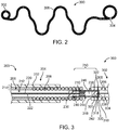
- FIG. 2 illustrates one exemplary configuration of a vaso-occlusive coil 300 in a natural state. In the natural state, the vaso-occlusive coil 300 transforms from the straight configuration illustrated in, for instance, FIG. 1 into a secondary shape.
- the secondary shaped may include both two and three dimensional shapes of a wide variety.
- FIG. 2 is just one example of a secondary shape of a vaso-occlusive coil 300.
- the vaso-occlusive coil 300 may incorporate synthetic fibers (not shown) over all or a portion of the vaso-occlusive coil 300 as is known in the art. These fibers may be attached directly to coil windings 308 or the fibers may be integrated into the vaso-occlusive coil 300 using a weave or braided configuration.
- the system 10 described herein may be used with occlusive coils 300 or other occlusive structures having a variety of configurations, and is not limited to occlusive coils 300 having a certain size or configuration.
- the system 10 further includes a power supply 400 for supplying direct current to the positive and negative conductors 220, 222. Activation of the power supply 400 causes electrical current to flow in a circuit including the positive and negative conductors 220, 222 and the resistive heating coil 210.
- the power supply 400 preferably includes an onboard energy source, such as batteries (e.g., a pair of AAA batteries), along with drive circuitry 402.
- the drive circuitry 402 may include one or more microcontrollers or processors configured to output a driving current.
- the power supply 400 illustrated in FIG. 1 includes a receptacle 404 configured to receive and mate with the proximal end 202 of the delivery wire assembly 200. Upon insertion of the proximal end 202 into the receptacle 404, the positive, negative electrical contracts 216, 224 disposed on the delivery wire assembly 200 electrically couple with corresponding contacts (not shown) located in the power supply 400.
- a visual indicator 406 (e.g., LED light) is used to indicate when the proximal end 202 of delivery wire assembly 200 has been properly inserted into the power supply 400.
- Another visual indicator 410 is activated if the onboard energy source needs to be recharged or replaced.
- the power supply 400 includes an activation trigger or button 408 that is depressed by the user to apply the electrical current to the resistive heating coil 210 via the positive and negative conductors 220, 222. Once the activation trigger 408 has been activated, the driver circuitry 402 automatically supplies current.
- the drive circuitry 402 typically operates by applying a substantially constant current, e.g., around 50-500 mA.
- a visual indicator 412 may indicate when the power supply 400 is supplying adequate current to the resistive heating coil 210.
- the vaso-occlusive coil 300 is attached to the pusher assembly 200 at junction 250.
- the attached vaso-occlusive coil 300 and pusher assembly 200 are threaded through the delivery catheter 100 to a target location (e.g., an aneurysm) in the patient's vasculature.
- a target location e.g., an aneurysm
- the vaso-occlusive coil 300 is pushed further distally until it's completely exits the distal and 104 of the delivery catheter 100.
- the power supply 400 is activated by depressing the trigger 408.
- the drive circuitry 402 in the power supply 400 applies a current to the positive and negative conductors 220, 222 through the positive and negative electrical contacts 216, 224.
- the resistive heating coil 210 generates heat.
- the generated heat raises the temperature of the tubular member 238 to its melting point, at which the tubular member 238 loses the structural integrity, becomes severed, and releases the vaso-occlusive coil 300 from the pusher assembly 200.
- the vaso-occlusive coil 300 is typically detached in less than one second.
- the heat generated by the heating coil 210 increases the temperature and pressure of air in the substantially fluid-tight chamber facilitating severance of the tubular member to create and release of the vaso-occlusive coil 300 from the pusher assembly 200.
- the vaso-occlusive coil 300 is ejected from the pusher assembly 200 by the increased pressure. This positive thrust force separating the vaso-occlusive coil 300 from the pusher assembly 200 ensures separation and prevents "sticky coils.”
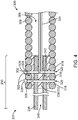
- FIG. 4 is a detailed view of the junction 250 between the pusher assembly 200 and the vaso-occlusive coil 300 of the vaso-occlusive device delivery system 10 depicted in FIG. 3 .
- Each of the pair of locking pins 322 depicted in FIG. 4 has an elongate portion 326 and an enlarged end portion 328.
- the enlarged end portions 328 prevent the locking pins 322 from completely passing through the vaso-occlusive coil 300.
- the proximal end of the stretch-resisting member 324 is looped around the elongate portion 326 of the distal most locking pin 322.
- the locking pin 322 mechanically secures the tubular member 238 to the vaso-occlusive coil 300 and the stretch-resisting member 324 to the vaso-occlusive coil 300 and the tubular member 238.
- This design particularly increases the tensile strength of the junction 250 between the pusher assembly 200 and the vaso-occlusive coil 300. In some embodiments, the tensile strength is around 0.136078kg (0.3 lbs). The design also facilitates manufacturing of vaso-occlusive device delivery systems 10.
- vaso-occlusive device delivery systems 10 depicted in FIGS. 5 to 11 are similar to the system 10 depicted in FIGS. 3 and 4 . Similar elements of this embodiment are identified with the same reference numbers as discussed above with respect to FIGS. 3 and 4 .
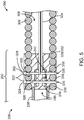
- FIG. 5 depicts a junction 250 between the pusher assembly 200 and the vaso-occlusive coil 300 that is similar to the junction 250 depicted in FIG. 4 .
- a pair of locking pins 322 pass through the spaces 320 between the open windings 318 and the distal end 242 of the tubular member 238, thereby mechanically securing the tubular member 238 and the pusher assembly 200 to the vaso-occlusive coil 300.
- the vaso-occlusive device delivery systems 10 depicted in FIG. 5 includes a support coil 218 positioned in the lumen 246 of the tubular member 238.
- the support coil 218 has open windings sized to allow a locking pin 322 to be inserted therethrough.
- the tubular member 238 is shrunken (e.g., by heat) around the support coil 218, thereby mechanically securing the support coil 218 in the tubular member 238.
- the locking pins 322 are inserted through the tubular member 238, they are also inserted through the open windings of the support coil 218 disposed in the distal end 242 of the tubular member 238. In this manner, the support coil 218 further strengthens the junction 250 between the pusher assembly 200 and the vaso-occlusive coil 300.
- the terminal distal end of the tubular member 238 is shrunken (e.g., by heat) around the proximal end of the stretch-resisting member 324, thereby securing the stretch-resisting member 324 to the tubular member 238.
- FIG. 6 depicts another junction 250 between the pusher assembly 200 and the vaso-occlusive coil 300 that is similar to the junction 250 depicted in FIG. 4 .
- the vaso-occlusive device delivery systems 10 depicted in FIG. 6 includes a "U" shaped locking pin 322 with two elongate portions 326 connected by a connecting portion 330.
- the connecting portion 330 remains outside of the vaso-occlusive coil 300 and performs the same function as the enlarged end portion 328 depicted in FIG. 4 , i.e., preventing the locking pin 322 from completely passing through the vaso-occlusive coil 300.
- the physical structure of the "U" shaped locking pin 322 eliminates the possibility that a locking pin 322 will completely slip through the vaso-occlusive coil 300.
- FIG. 7 depicts a vaso-occlusive device delivery system 10, similar to the one depicted in FIG. 3 , except that the pair of locking pins 322 depicted in FIG. 3 has been replaced with a "U" shaped locking pin 322, as shown in FIG. 6 and described above.
- the distal coil portion 208 of the pusher assembly 200 includes a set of marker coils 226 for fluoroscopic visualization.
- the distal end of the distal coil portion 208 is tapered outward and has open pitch windings to allow adhesive 332 to enter to form the proximal seal 230.
- the junction 250 includes a PTFE sleeve 234 disposed around the detachment zone 244.
- FIG. 8 depicts a junction 250 between the pusher assembly 200 and the vaso-occlusive coil 300 that is almost identical to the junction 250 depicted in FIGS. 6 and 7 .
- the junction 250 depicted in FIG. 8 has a "U" shaped locking pin 322.
- the difference is that the junction 250 depicted in FIG. 8 includes a tubular member 238 with an open distal end 242.
- the junction 250 does not include a distal seal 228, however a small amount of adhesive 332 is disposed in the spaces 320 between the open windings 318 of the vaso-occlusive coil 300 to secure the "U" shaped locking pin 322 to the vaso-occlusive coil 300.
- the design depicted in FIG. 8 has enhanced flexibility compared to the design depicted in FIGS. 6 and 7 because of the removal of the distal seal 228 and the reduced amount of adhesive 332.
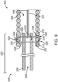
- FIG. 9 depicts a junction 250 between the pusher assembly 200 and the vaso-occlusive coil 300 that is similar to the junction 250 depicted in FIG. 8 .
- the junction 250 depicted in FIG. 9 has a tubular member 238 with an open distal end 242.
- the locking pin 322 depicted in FIG. 9 is shaped like a paper clip with a connection portion 330 and a hook portion 334 connected by one of two elongate potions 326. That elongate portion 326 extends through the vaso-occlusive coil 300 such that the connection portion 330 and the hook portion 334 are on opposite sides of the vaso-occlusive coil 300.
- the hook portion 334 exits from the vaso-occlusive coil 300 through one space 320 and reenters the vaso-occlusive coil 300 through another space 320, thereby further securing the locking pin 322 to the vaso-occlusive coil 300.
- FIG. 10 depicts another junction 250 between the pusher assembly 200 and the vaso-occlusive coil 300 that is similar to the junction 250 depicted in FIG. 8 .
- the junction 250 depicted in FIG. 10 has a "U" shaped locking pin 322 and a small amount of adhesive 332 disposed in the spaces 320 between the open windings 318 of the vaso-occlusive coil 300.
- a polymer layer 336 e.g., polyethylene terephthalate
- the polymer layer 336 may form a tubular body.
- the polymer layer 336 prevents radial movement of the locking pin 322, thereby further securing the locking pin 322 to the vaso-occlusive coil 300.
- FIG. 11 depicts a junction 250 between the pusher assembly 200 and the vaso-occlusive coil 300 that is similar to the junction 250 depicted in FIG. 8 .
- the junction 250 depicted in FIG. 11 has a tubular member 238 with an open distal end 242.
- the junction 250 depicted in FIG. 11 has only a single locking pin 322.
- the locking pin 322 has an elongate portion capped on both ends by respective enlarged end portions 328. These enlarged end portions 328 may be formed by a mechanical process, such as applying pressure to the two ends of the locking pin 322.
- a metal tube 338 is added to the proximal end of the vaso-occlusive coil 300 (e.g., by welding).
- the metal tube 338 includes a pair of opposing openings 340 through which the locking pin passes 322, thereby anchoring the locking pin 322 and the tubular member 238 to the metal tube 338 and the vaso-occlusive coil 300.
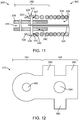
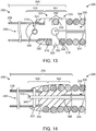
- FIGS. 12-14 depict a link 310 and a junction 250 between the pusher assembly 200 and the vaso-occlusive coil 300 including a link 310.
- the link 310 (shown in isolation in FIG. 12 ) is a flattened body having has proximal and distal portions 342, 344.
- the link 310 defines proximal and distal openings 346, 348 in its respective proximal and distal portions 342, 344, and a plurality of fingers 350 in its distal end 344.
- the link 310 may be formed from a non-conductive material.
- the distal portion 344 of the link 310 is secured to the vaso-occlusive coil 300 at the proximal end 302 thereof.
- the proximal end 302 of the vaso-occlusive coil 300 includes open pitch windings 318 with spaces 320 therebetween.
- the fingers 350 at the distal end 344 of the link 310 are interlaced into the spaces 320 between the open pitch windings 318. Mechanical interference between the fingers 350 and the open pitch windings 318 secure the link 310 to the vaso-occlusive coil 300.
- a stretch-resisting member 324 such as a suture, is secured to the distal end 304 of the vaso-occlusive coil 300 and extends through the lumen 306 to the proximal end 302 where it is secured to the link 310.
- the stretch-resisting member 324 is secured by looping through the distal opening 348 of the link 310.
- the proximal portion 342 of the link 310 is secured to the tubular member 238 by a locking pin 322. As shown in FIGS. 13 and 14 , the proximal portion 342 of the link 310 is inserted into the tube lumen 246 at the distal end 242 of the tubular member 238. A locking pin 322 is inserted through the tubular member and the proximal opening 346 in the link, thereby securing the link 310 to the tubular member 238. An adhesive 332 is disposed inside and outside of the junction 250, further securing the tubular member 238, locking pin 322, link 310, vaso-occlusive coil 300, and stretch-resisting member 324 together.
- FIGS. 15 and 16 depict two junctions 250 between respective pusher assemblies 200 and vaso-occlusive coils 300, each junction 250 including a tubular marker 312.
- the proximal end of the stretch-resisting member 324 is disposed in the lumen 246 of the tubular member 238 at the distal end 242 thereof.
- the distal end 242 of the tubular member 238 is, in turn, disposed in the lumen 306 of the vaso-occlusive coil 300 at the proximal end 302 thereof.
- a tubular marker 312 is crimped around the proximal end 302 of the vaso-occlusive coil 300, the distal end 242 of the tubular member 238, and the proximal end of the stretch-resisting member 324 to mechanically secure the vaso-occlusive coil 300, the tubular member 238, and the stretch-resisting member 324 to each other.
- the tubular marker 312 may be made of a radiopaque material, such as platinum or iridium.
- an adhesive 332 is disposed in the vaso-occlusive lumen 306 to further secure the vaso-occlusive coil 300, the tubular member 238, and the stretch-resisting member 324 together.
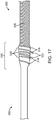
- FIG. 17 is a side view photograph of a junction 250 between the pusher assembly 200 and the vaso-occlusive coil 300 according to another embodiment of the invention.
- the junction 250 includes opening windings 318 defining spaces 320 therebetween.
- the junction also includes locking pins 322 disposed in the spaces 320.
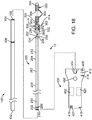
- FIG. 18 depicts a vaso-occlusive coil delivery system 10 according to an example which is not part of the invention.
- the vaso-occlusive coil delivery system 10 depicted in FIG. 18 is similar in some aspects to the one depicted in FIG. 1 .
- One major difference is that the system 10 depicted in FIG. 18 includes an electrolytic detachment system, whereas the one depicted in FIG. 1 includes a thermal detachment system.
- the system 10 in FIG. 18 includes a pusher assembly 200 having a core wire 252, having proximal and distal ends 254, 256.
- the core wire 252 that extends from the proximal end 202 of the delivery wire assembly 200 to a location that is distal with respect to the distal end 204 of the delivery wire assembly 200.
- the core wire 252 is disposed within a lumen 212 that extends within an interior portion of the delivery wire assembly 200.
- the core wire 252 is formed from an electrically conductive material such as stainless steel wire.
- the proximal end 214 of the core wire 252 (shown in phantom) is electrically coupled to an electrical contact 216 located at the proximal end 202 of the delivery wire assembly 200.
- the electrical contact 216 may be formed from a metallic solder (e.g., gold) that is configured to interface with a corresponding electrical contact (not shown) in the power supply 400.
- a portion of the core wire 252 is advantageously coated with an insulative coating 258.
- the insulative coating 258 may include polyimide.
- the entire length of the core wire 252 is coated with an insulative coating 258 except for a small region 260 located in portion of the core wire 252 that extends distally with respect to the distal end 204 of the of the delivery wire assembly 200.
- This "bare" portion of the core wire 252 forms the electrolytic detachment zone 260 which dissolves upon application of electrical current from the power supply 400.
- FIG. 18 Another difference between the vaso-occlusive coil delivery system 10 depicted in FIG. 18 and the one depicted in FIG. 1 is that the system 10 depicted in FIG. 18 includes a link 500.
- An occlusive coil 300 is shown in FIG. 18 as being secured to the pusher assembly 200 via a delivery wire adapter 500.
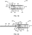
- the link 500 has a proximal end 502 and a distal end 504, and includes a link body 506 and a cap 508 at the proximal end 502 thereof (best seen in FIGS. 19-23 ).
- the link 500 defines a radially centered link lumen 510 and a link opening 512 in communication with the link lumen 510 in the proximal end 502 of the link 500. As shown in FIGS.
- the link opening 512 is in the cap and concentric therewith.
- the link 500 also defines a pair of link detents 514 extending radially from the link body 506.
- the detents 514 are configured to interface with the vaso-occlusive coil 300.
- the link 500 also forms an aperture 518 at its distal end 504.
- the link 500 may be made from suitable materials such as polymers, stainless steel, iridium, platinum, gold, rhenium, tungsten, palladium, rhodium, and tantalum.
- the link 500 may be injection molded or cut (i.e., micro-machined) from blocks of suitable materials.
- radiopaque materials are preferred due to their fluoroscopic visibility during use to allow the clinicians to precisely place and detach the embolic coil relatively to the treatment site (e.g., aneurysm/AVM).
- the link 500 is compressible, it can be easily inserted or positioned into the proximal end of the coil lumen 306 and secured to the vaso-occlusive coil 300, while minimizing bending of and damage to the coil 300. Further, the outer diameter of the link body 506 is about the same as the diameter of the coil lumen 306, thereby centering the link 500 with respect to the vaso-occlusive coil 300.
- FIG. 19 depicts a link 500 secured to a vaso-occlusive coil 300 according to one example which is not part of the invention.
- the occlusive coil 300 includes a plurality of coil windings 308.
- the coil windings 308 are generally helical about a central axis disposed along the lumen 306 of the occlusive coil 300.
- the proximal end 302 of the occlusive coil 300 has coil windings 308 with an open pitch configuration. For example, several of the proximal coil windings 308 may be spread open in the open pitch configuration (illustrated by arrow A in FIG. 18 ).
- the remaining distal portion of the occlusive coil 300 may have a closed pitch configuration as illustrated in FIGS. 18 and 19 .
- the distal portion of the occlusive coil 300 may also include one or more open pitch segments or regions (or the entire occlusive coil 300 may be open pitched).
- the open pitch of the proximal coil windings 308 defines a coil opening 314 for the interface fit with the detents 514 of the link 500.
- an adhesive 332 may also be applied to the interface between the link 500 and the proximal coil windings 308 of the occlusive coil 300.
- the adhesive 332 may include an epoxy material which is cured or hardened through the application of heat or UV radiation.
- the adhesive 332 may include a thermally cured, two-part epoxy such as EPO-TEK® 353ND-4 available from Epoxy Technology, Inc., 14 Fortune Drive, Billerica, MA.
- the adhesive 332 encapsulates and locates the link 500 substantially concentrically relative to the occlusive coil 300 and prevents tangential motion that may be induced by axially tensile loading of the occlusive coil 300.
- adjacent coil windings 308 on either side of the detents 514 may be joined by laser tack, spot, or continuous welding.
- laser melting of the detents 514 over the coil windings 308 may be used to mechanically join the link 500 to the occlusive coil 300.
- the link body 506 also defines radially directed link ports 516 in communication with the link lumen 510.
- an adhesive 332 can be introduced into the link lumen 510 via the link ports 516.
- the adhesive 332 bonds the distal end 256 of a core wire 252 to the link 500. In this way, the distal end 256 of the core wire 252 can be secured to the link 500 without having to bend, and therefore weaken, the core wire 252.
- FIGS. 19 and 20 also depict a stretch-resisting member 324 disposed in the vaso-occlusive coil lumen 306 and having proximal and distal ends.
- the proximal end of the stretch-resisting member 324 is secured the link 500 and the distal end of the stretch-resisting member 324 is attached to the distal end 304 of the vaso-occlusive coil 300.
- the stretch-resisting member 324 includes a distal cap 316.
- the stretch-resisting member 324 may take the form of a filament or the like.
- the stretch-resisting member 324 may be formed from a polymeric material such as, for instance, suture filament material.
- the stretch-resisting member 324 exists initially as only a single filament that extends from the distal cap 316. The free end of this filament is fed through the aperture 518 located at the distal end 504 of the link 500. The free end of the stretch-resisting member 324 is then pulled back toward the distal end 304 of the vaso-occlusive coil 300 where the same is bonded to the distal cap 316 to form the complete structure as illustrated in FIGS. 19 and 20 . Heat bonding may be used to fuse or otherwise secure the free end of the stretch-resisting member 324 to the distal cap 316.
- stretch-resisting member 324 may also be used depending on the nature of the material used for the stretch-resisting member 324. These include, for instance, welding, adhesive bonding, and the like.
- the use of a stretch-resisting member 324 is entirely optional, however.
- Other examples may utilize an occlusive coil 300 that does not contain a stretch-resisting member 324.
- the proximal tubular portion 206 and a distal coil portion 208 form a return electrode for the delivery system 10.
- the core wire 252 forms a first conductive path 262 between the electrical contact 216 and the electrolytic detachment zone 220.
- This first conductive path 262 may comprise the anode (+) of the electrolytic circuit when the delivery wire assembly 200 is operatively coupled to the power supply 400.
- a second conductive path 264 is formed by the proximal tubular portion 206 and a distal coil portion 208 of the delivery wire assembly 200.
- the second conductive path 264 is electrically isolated from the first conductive path 242.
- the second conductive path 244 may comprise the cathode (-) or ground electrode for the electrical circuit.
- An electrical contact 266 for the second conductive path 264 may be disposed on a proximal end of the tubular portion 206.
- the electrical contact 266 is simply an exposed portion of the tubular portion 206 since the tubular portion 206 is part of the second conductive path 264.
- a proximal portion of the tubular portion 206 that is adjacent to the electrical contact 216 may be covered with an insulative coating 258 such as polyimide.
- An exposed region of the tubular portion 206 that does not have the insulative coating may form the electrical contact 266.
- the electrical contact 266 may be a ring type electrode or other contact that is formed on the exterior of the tubular portion 206.
- the electrical contact 266 is configured to interface with a corresponding electrical contact (not shown) in the power supply 400 when the proximal end 202 of the delivery wire assembly 200 is inserted into the power supply 400.
- the electrical contact 266 of the second conductive path 264 is, of course, electrically isolated with respect to the electrical contact 216 of the first conductive path 262.
- the power supply 400 depicted in FIG. 18 is similar to the one depicted in FIG. 1 , however, it is configured for electrolytic (vs. thermal) detachment. Accordingly, in addition to the features of the power supply 400 depicted in FIG. 1 , the power supply 400 depicted in FIG. 18 includes several alternative and additional features.
- the drive circuitry 402 typically operates by applying a substantially constant current (e.g., around 1.5 mA).
- the power supply 400 may include optional detection circuitry 420 that is configured to detect when the occlusive coil 300 has detached from the core wire 252. The detection circuitry 420 may identify detachment based upon a measured impedance value.
- a visual indicator 412 may indicate when the power supply 400 is being supplied to the current to the sacrificial electrolytic detachment zone 220.
- Another visual indicator 414 may indicate when the occlusive coil 300 has detached from the delivery wire 210.
- an audible signal e.g., beep
- tactile signal e.g., vibration or buzzer
- the detection circuitry 420 may be configured to disable the drive circuitry 402 upon sensing detachment of the occlusive coil 300.
- the power supply 400 may also contain another visual indicator 416 that indicates to the operator when a legacy, non-bipolar delivery wire assembly is inserted into the power supply 400.
- a legacy, non-bipolar delivery wire assembly is inserted into the power supply 400.
- prior devices used a separate return electrode that typically was in the form of a needle that was inserted into the groin area of the patient.
- the power supply 400 is configured to detect when one of the older non-bipolar delivery wire assemblies has been inserted. Under such situations, the visual indicator 416 (e.g., LED) is turned on and the user is advised to insert the separate return electrode (not shown in FIG. 1 ) into a port 418 located on the power supply 400.
- the visual indicator 416 e.g., LED
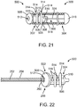
- FIGS. 21-23 depict a link 500 secured to a vaso-occlusive coil 300 according to another example which is not part of the invention.
- the link 500 depicted in FIGS. 21-23 is similar to the one depicted in FIGS. 19-20 , except that the link 500 defines two pairs of detents 514 instead of one.
- the two pairs of detents 514 interface with corresponding coil openings 314 formed by the open pitch of the proximal coil windings 308 to secure the link 500 to the vaso-occlusive coil 300.
- the link 500 designs described above improve assembly process learning curve, tack time, yield, and Cost of Goods.
Claims (9)
- Gefäßverschlusswendel-Zuführanordnung (10), umfassend:eine Drückeranordnung (200), welche eine Längsachse definiert;ein längliches röhrenförmiges Element (238), das an einem distalen Ende (204) der Drückeranordnung (200) befestigt ist und sich distal von diesem erstreckt, wobei das röhrenförmige Element (238) zur Längsachse der Drückeranordnung (200) ausgerichtet ist und eine röhrenförmige Element-Wand aufweist; undeine Gefäßverschlusswendel (300), welche ein axiales Lumen (306) definiert und eine erste und eine zweite Gefäßverschlusswendelwicklung (318) in einem proximalen Endteil (302) davon aufweist, wobei die erste und die zweite Wicklung (318) eine Gefäßverschlusswendelöffnung (320) dazwischen definieren, wobei ein distaler Endteil (242) der röhrenförmigen Element-Wand sich bis in das axiale Lumen (306) der Gefäßverschlusswendel (300) erstreckt;dadurch gekennzeichnet, dass die Anordnung (10) weiter umfasst:einen Verriegelungsstift (322), der sich durch die Gefäßverschlusswendelöffnung (320) und durch den distalen Endteil (242) der röhrenförmigen Element-Wand, der in dem axialen Lumen (306) der Gefäßverschlusswendel (300) angeordnet ist, erstreckt, wodurch er das röhrenförmige Element (238) an der Gefäßverschlusswendel (300) verriegelt.
- Gefäßverschlusswendel-Zuführanordnung (10) nach Anspruch 1, weiter ein ausdehnungswiderstandsfähiges Element (324) umfassend, das in dem axialen Lumen (306) der Gefäßverschlusswendel (300) angeordnet ist, wobei ein proximales Ende des ausdehnungswiderstandsfähigen Elements (324) mit dem Verriegelungsstift (322) gekoppelt ist.
- Gefäßverschlusswendel-Zuführanordnung (10) nach Anspruch 1, weiter ein Klebemittel (332) umfassend, welches das röhrenförmige Element (238) an der Gefäßverschlusswendel (300) befestigt, wobei das Klebemittel (332) in dem axialen Lumen (306) der Gefäßverschlusswendel (300) und in der Gefäßverschlusswendelöffnung (320) zwischen der ersten und der zweiten Gefäßverschlusswendelwicklung (318) angeordnet ist.
- Gefäßverschlusswendel-Zuführanordnung (10) nach Anspruch 1, wobei das röhrenförmige Element (238) ein axiales röhrenförmiges Element-Lumen (246) definiert, und weiter eine Stützwendel (218) umfassend, die in dem axialen Lumen (246) des röhrenförmigen Elements (238) angeordnet ist, wobei die Stützwendel (218) eine erste und eine zweite Stützwendelwicklung aufweist, welche eine Stützwendelöffnung dazwischen definieren, wobei der Verriegelungsstift (322) sich weiter durch die Stützwendelöffnung erstreckt.
- Gefäßverschlusswendel-Zuführanordnung (10) nach Anspruch 4, wobei die Stützwendel (218) an dem röhrenförmigen Element (238) befestigt ist.
- Gefäßverschlusswendel-Zuführanordnung (10) nach Anspruch 1, wobei der Verriegelungsstift (322) einen vergrößerten Endteil (328) aufweist, der sich lateral auswärts von der Gefäßverschlusswendelöffnung (320) erstreckt und so dimensioniert und geformt ist, dass er dessen Passieren durch die Gefäßverschlusswendelöffnung (320) verhindert.
- Gefäßverschlusswendel-Zuführanordnung (10) nach Anspruch 1, wobei die erste und die zweite Gefäßverschlusswendelwicklung (318) ein erstes Paar Wicklungen (318) darstellt, wobei die Gefäßverschlusswendelöffnung (320) eine erste Gefäßverschlusswendelöffnung (320) ist, wobei der Verriegelungsstift (322) ein erster Verriegelungsstift (322) ist, wobei die Anordnung (10) weiter umfasst:eine zweite Gefäßverschlusswendelöffnung (320), definiert durch ein zweites Paar Gefäßverschlusswendelwicklungen (318); undeinen zweiten Verriegelungsstift (322), der sich durch die zweite Gefäßverschlusswendelöffnung (320) und durch den distalen Endteil (242) der röhrenförmigen Element-Wand, der in dem axialen Lumen (306) der Gefäßverschlusswendel (300) angeordnet ist, erstreckt, wodurch er das röhrenförmige Element (238) weiter an der Gefäßverschlusswendel (300) verriegelt.
- Gefäßverschlusswendel-Zuführanordnung (10) nach Anspruch 7, weiter einen Verriegelungsstift-Steckverbinder (330) umfassend, der benachbart zu einer Außenfläche der Gefäßverschlusswendel (300) angeordnet ist, wobei jeder des ersten und des zweiten Verriegelungsstifts (322) einen äußeren Teil aufweist, der sich lateral auswärts von einer jeweiligen ersten und zweiten Gefäßverschlusswendelöffnung (320) erstreckt, und wobei der Verriegelungsstift-Steckverbinder (330) an den jeweiligen äußeren Teilen des ersten und des zweiten Verriegelungsstifts (322) befestigt ist, wobei das System weiter ein Klebemittel (332) umfasst, das den ersten und den zweiten Verriegelungsstift (322) und den Verriegelungsstift-Steckverbinder (330) an der Gefäßverschlusswendel (300) befestigt.
- Gefäßverschlusswendel-Zuführanordnung (10) nach Anspruch 7, wobei der erste Verriegelungsstift (322) einen äußeren Teil aufweist, der einen Haken (334) umfasst, der sich lateral auswärts von dem ersten Verriegelungsstift (322) und durch den distalen Endteil (242) der röhrenförmigen Element-Wand, der in dem axialen Lumen (306) der Gefäßverschlusswendel (300) angeordnet ist, erstreckt, wodurch er das röhrenförmige Element (238) an der Gefäßverschlusswendel (300) verriegelt, und wobei ein distales Ende des Hakens (334) sich in den zweiten Verriegelungsstift (322) und durch den distalen Endteil (242) der röhrenförmigen Element-Wand, der in dem axialen Lumen (306) der Gefäßverschlusswendel (300) angeordnet ist, erstreckt, wodurch er das röhrenförmige Element (238) an der Gefäßverschlusswendel (300) verriegelt.
Applications Claiming Priority (3)
| Application Number | Priority Date | Filing Date | Title |
|---|---|---|---|
| US201361867957P | 2013-08-20 | 2013-08-20 | |
| US201361897151P | 2013-10-29 | 2013-10-29 | |
| PCT/US2014/050755 WO2015026576A1 (en) | 2013-08-20 | 2014-08-12 | Vaso-occlusive device delivery system |
Publications (2)
| Publication Number | Publication Date |
|---|---|
| EP3035867A1 EP3035867A1 (de) | 2016-06-29 |
| EP3035867B1 true EP3035867B1 (de) | 2017-07-19 |
Family
ID=51454962
Family Applications (1)
| Application Number | Title | Priority Date | Filing Date |
|---|---|---|---|
| EP14758448.6A Active EP3035867B1 (de) | 2013-08-20 | 2014-08-12 | Freisetzungssystem für vasookklusive vorrichtung |
Country Status (5)
| Country | Link |
|---|---|
| US (1) | US9480479B2 (de) |
| EP (1) | EP3035867B1 (de) |
| JP (1) | JP6359664B2 (de) |
| CN (1) | CN105530874B (de) |
| WO (1) | WO2015026576A1 (de) |
Families Citing this family (32)
| Publication number | Priority date | Publication date | Assignee | Title |
|---|---|---|---|---|
| EP2588042A4 (de) | 2010-06-29 | 2015-03-18 | Artventive Medical Group Inc | Verringerung des flusses durch eine rohrkonstruktion |
| US9326774B2 (en) | 2012-08-03 | 2016-05-03 | Covidien Lp | Device for implantation of medical devices |
| US9095344B2 (en) * | 2013-02-05 | 2015-08-04 | Artventive Medical Group, Inc. | Methods and apparatuses for blood vessel occlusion |
| US8984733B2 (en) | 2013-02-05 | 2015-03-24 | Artventive Medical Group, Inc. | Bodily lumen occlusion |
| US10149968B2 (en) | 2013-06-14 | 2018-12-11 | Artventive Medical Group, Inc. | Catheter-assisted tumor treatment |
| US9737308B2 (en) | 2013-06-14 | 2017-08-22 | Artventive Medical Group, Inc. | Catheter-assisted tumor treatment |
| US9737306B2 (en) | 2013-06-14 | 2017-08-22 | Artventive Medical Group, Inc. | Implantable luminal devices |
| US9636116B2 (en) | 2013-06-14 | 2017-05-02 | Artventive Medical Group, Inc. | Implantable luminal devices |
| US10363043B2 (en) | 2014-05-01 | 2019-07-30 | Artventive Medical Group, Inc. | Treatment of incompetent vessels |
| US9808256B2 (en) | 2014-08-08 | 2017-11-07 | Covidien Lp | Electrolytic detachment elements for implant delivery systems |
| US9814466B2 (en) | 2014-08-08 | 2017-11-14 | Covidien Lp | Electrolytic and mechanical detachment for implant delivery systems |
| US10925611B2 (en) | 2015-01-20 | 2021-02-23 | Neurogami Medical, Inc. | Packaging for surgical implant |
| US10736730B2 (en) | 2015-01-20 | 2020-08-11 | Neurogami Medical, Inc. | Vascular implant |
| CN107205736B (zh) * | 2015-01-20 | 2021-04-09 | 纽罗加米医药公司 | 用于颅内动脉瘤的治疗的微型移植物及使用方法 |
| US9717503B2 (en) | 2015-05-11 | 2017-08-01 | Covidien Lp | Electrolytic detachment for implant delivery systems |
| EP3378415A4 (de) * | 2015-11-19 | 2019-10-09 | Kaneka Corporation | In-vivo-verweilelement und positionierungsvorrichtung für in-vivo-verweilelement mit diesem in-vivo-verweilelement |
| US10188395B2 (en) * | 2015-12-16 | 2019-01-29 | DePuy Synthes Products, Inc. | Non-planar heating chamber detachment mechanism of an implantable vaso-occluding device delivery system |
| US10321915B2 (en) | 2015-12-18 | 2019-06-18 | Stryker Corporation | Vaso-occlusive device and delivery assembly |
| US10813644B2 (en) | 2016-04-01 | 2020-10-27 | Artventive Medical Group, Inc. | Occlusive implant and delivery system |
| US10285710B2 (en) | 2016-06-01 | 2019-05-14 | DePuy Synthes Products, Inc. | Endovascular detachment system with flexible distal end and heater activated detachment |
| US10828039B2 (en) | 2016-06-27 | 2020-11-10 | Covidien Lp | Electrolytic detachment for implantable devices |
| US10828037B2 (en) | 2016-06-27 | 2020-11-10 | Covidien Lp | Electrolytic detachment with fluid electrical connection |
| US11051822B2 (en) | 2016-06-28 | 2021-07-06 | Covidien Lp | Implant detachment with thermal activation |
| EP3490464A4 (de) | 2016-07-29 | 2020-07-29 | Wallaby Medical, Inc. | Systeme und verfahren zur einführung eines implantats |
| US11291457B2 (en) * | 2016-12-08 | 2022-04-05 | Lifetech Scientific (Shenzhen) Co. Ltd. | Lung volume-reducing elastic implant and instrument |
| CN108210133B (zh) * | 2016-12-16 | 2020-09-04 | 先健科技(深圳)有限公司 | 植入体 |
| WO2018129478A1 (en) * | 2017-01-07 | 2018-07-12 | Balt Usa | Enhanced thermal pusher assembly |
| WO2019026364A1 (ja) * | 2017-07-31 | 2019-02-07 | 株式会社カネカ | 生体内留置具、生体内留置具送達システムおよび生体内留置具の製造方法 |
| US11039840B2 (en) * | 2017-12-11 | 2021-06-22 | Microvention, Inc. | Implant detachment |
| CN109171865A (zh) * | 2018-10-15 | 2019-01-11 | 济南市儿童医院(山东大学齐鲁儿童医院) | 介入装置 |
| WO2023154757A1 (en) | 2022-02-11 | 2023-08-17 | Stryker Corporation | Vaso-occlusive device and delivery assembly |
| US20240038419A1 (en) * | 2022-07-26 | 2024-02-01 | Paul James LINGANE | Devices, systems and methods for detachment of releasable devices |
Family Cites Families (12)
| Publication number | Priority date | Publication date | Assignee | Title |
|---|---|---|---|---|
| US4994069A (en) * | 1988-11-02 | 1991-02-19 | Target Therapeutics | Vaso-occlusion coil and method |
| US5984929A (en) | 1997-08-29 | 1999-11-16 | Target Therapeutics, Inc. | Fast detaching electronically isolated implant |
| US6277126B1 (en) * | 1998-10-05 | 2001-08-21 | Cordis Neurovascular Inc. | Heated vascular occlusion coil development system |
| DE10010840A1 (de) * | 1999-10-30 | 2001-09-20 | Dendron Gmbh | Vorrichtung zur Implantation von Occlusionswendeln |
| CN101045005A (zh) * | 2001-11-07 | 2007-10-03 | 微温森公司 | 具有多轴二级构型的微线圈血管阻塞器件 |
| US9636115B2 (en) | 2005-06-14 | 2017-05-02 | Stryker Corporation | Vaso-occlusive delivery device with kink resistant, flexible distal end |
| US8585732B2 (en) * | 2006-06-14 | 2013-11-19 | DePuy Synthes Products, LLC | Retrieval device with sidewall grippers |
| CA2692962C (en) * | 2007-07-27 | 2016-09-13 | Microvention, Inc. | Detachable coil incorporating stretch resistance |
| JP5366974B2 (ja) * | 2007-12-21 | 2013-12-11 | マイクロベンション インコーポレイテッド | 分離可能なインプラントの分離域の位置を決定するシステムおよび方法 |
| EP2240093B1 (de) * | 2008-01-04 | 2013-04-24 | Boston Scientific Scimed, Inc. | Ablösemechanismen für implantierbare vorrichtungen |
| EP2346415B1 (de) * | 2008-10-13 | 2012-11-21 | Stryker Corporation | Gefässverschliessendes spulenabgabesystem |
| US20100160944A1 (en) | 2008-12-24 | 2010-06-24 | Boston Scientific Scimed, Inc. | Thermally detachable embolic assemblies |
-
2014
- 2014-08-12 CN CN201480046190.9A patent/CN105530874B/zh active Active
- 2014-08-12 US US14/457,970 patent/US9480479B2/en active Active
- 2014-08-12 WO PCT/US2014/050755 patent/WO2015026576A1/en active Application Filing
- 2014-08-12 EP EP14758448.6A patent/EP3035867B1/de active Active
- 2014-08-12 JP JP2016536307A patent/JP6359664B2/ja active Active
Non-Patent Citations (1)
| Title |
|---|
| None * |
Also Published As
| Publication number | Publication date |
|---|---|
| US9480479B2 (en) | 2016-11-01 |
| CN105530874A (zh) | 2016-04-27 |
| EP3035867A1 (de) | 2016-06-29 |
| WO2015026576A1 (en) | 2015-02-26 |
| CN105530874B (zh) | 2018-02-02 |
| JP2016530947A (ja) | 2016-10-06 |
| US20150057700A1 (en) | 2015-02-26 |
| JP6359664B2 (ja) | 2018-07-18 |
Similar Documents
| Publication | Publication Date | Title |
|---|---|---|
| EP3035867B1 (de) | Freisetzungssystem für vasookklusive vorrichtung | |
| EP2967573B1 (de) | Freisetzungssystem für vasookklusive vorrichtung | |
| EP2346415B1 (de) | Gefässverschliessendes spulenabgabesystem | |
| US20230225738A1 (en) | Vaso-occlusive device delivery system | |
| US8992563B2 (en) | Delivery wire assembly for occlusive device delivery system | |
| EP2416712B1 (de) | Abgabedraht für ein okklusionsvorrichtungs-abgabesystem | |
| EP2967572B1 (de) | Freisetzungssystem für vasookklusive vorrichtung | |
| US8398671B2 (en) | Electrical contact for occlusive device delivery system | |
| US20100234872A1 (en) | Electrical contact for occlusive device delivery system | |
| US20120209310A1 (en) | Vaso-occlusive device delivery system | |
| US9314250B2 (en) | Electrical contact for occlusive device delivery system | |
| US20100268251A1 (en) | Delivery wire for occlusive device delivery system and method of manufacture | |
| WO2011060128A2 (en) | Delivery wire assembly for occlusive device delivery system |
Legal Events
| Date | Code | Title | Description |
|---|---|---|---|
| PUAI | Public reference made under article 153(3) epc to a published international application that has entered the european phase |
Free format text: ORIGINAL CODE: 0009012 |
|
| 17P | Request for examination filed |
Effective date: 20160118 |
|
| AK | Designated contracting states |
Kind code of ref document: A1 Designated state(s): AL AT BE BG CH CY CZ DE DK EE ES FI FR GB GR HR HU IE IS IT LI LT LU LV MC MK MT NL NO PL PT RO RS SE SI SK SM TR |
|
| AX | Request for extension of the european patent |
Extension state: BA ME |
|
| DAX | Request for extension of the european patent (deleted) | ||
| GRAP | Despatch of communication of intention to grant a patent |
Free format text: ORIGINAL CODE: EPIDOSNIGR1 |
|
| INTG | Intention to grant announced |
Effective date: 20170206 |
|
| GRAS | Grant fee paid |
Free format text: ORIGINAL CODE: EPIDOSNIGR3 |
|
| GRAA | (expected) grant |
Free format text: ORIGINAL CODE: 0009210 |
|
| AK | Designated contracting states |
Kind code of ref document: B1 Designated state(s): AL AT BE BG CH CY CZ DE DK EE ES FI FR GB GR HR HU IE IS IT LI LT LU LV MC MK MT NL NO PL PT RO RS SE SI SK SM TR |
|
| REG | Reference to a national code |
Ref country code: GB Ref legal event code: FG4D |
|
| REG | Reference to a national code |
Ref country code: CH Ref legal event code: EP |
|
| REG | Reference to a national code |
Ref country code: IE Ref legal event code: FG4D |
|
| REG | Reference to a national code |
Ref country code: AT Ref legal event code: REF Ref document number: 909582 Country of ref document: AT Kind code of ref document: T Effective date: 20170815 |
|
| REG | Reference to a national code |
Ref country code: DE Ref legal event code: R096 Ref document number: 602014012047 Country of ref document: DE |
|
| REG | Reference to a national code |
Ref country code: NL Ref legal event code: MP Effective date: 20170719 |
|
| REG | Reference to a national code |
Ref country code: LT Ref legal event code: MG4D |
|
| REG | Reference to a national code |
Ref country code: AT Ref legal event code: MK05 Ref document number: 909582 Country of ref document: AT Kind code of ref document: T Effective date: 20170719 |
|
| PG25 | Lapsed in a contracting state [announced via postgrant information from national office to epo] |
Ref country code: LT Free format text: LAPSE BECAUSE OF FAILURE TO SUBMIT A TRANSLATION OF THE DESCRIPTION OR TO PAY THE FEE WITHIN THE PRESCRIBED TIME-LIMIT Effective date: 20170719 Ref country code: FI Free format text: LAPSE BECAUSE OF FAILURE TO SUBMIT A TRANSLATION OF THE DESCRIPTION OR TO PAY THE FEE WITHIN THE PRESCRIBED TIME-LIMIT Effective date: 20170719 Ref country code: HR Free format text: LAPSE BECAUSE OF FAILURE TO SUBMIT A TRANSLATION OF THE DESCRIPTION OR TO PAY THE FEE WITHIN THE PRESCRIBED TIME-LIMIT Effective date: 20170719 Ref country code: SE Free format text: LAPSE BECAUSE OF FAILURE TO SUBMIT A TRANSLATION OF THE DESCRIPTION OR TO PAY THE FEE WITHIN THE PRESCRIBED TIME-LIMIT Effective date: 20170719 Ref country code: AT Free format text: LAPSE BECAUSE OF FAILURE TO SUBMIT A TRANSLATION OF THE DESCRIPTION OR TO PAY THE FEE WITHIN THE PRESCRIBED TIME-LIMIT Effective date: 20170719 Ref country code: NL Free format text: LAPSE BECAUSE OF FAILURE TO SUBMIT A TRANSLATION OF THE DESCRIPTION OR TO PAY THE FEE WITHIN THE PRESCRIBED TIME-LIMIT Effective date: 20170719 Ref country code: NO Free format text: LAPSE BECAUSE OF FAILURE TO SUBMIT A TRANSLATION OF THE DESCRIPTION OR TO PAY THE FEE WITHIN THE PRESCRIBED TIME-LIMIT Effective date: 20171019 |
|
| PG25 | Lapsed in a contracting state [announced via postgrant information from national office to epo] |
Ref country code: ES Free format text: LAPSE BECAUSE OF FAILURE TO SUBMIT A TRANSLATION OF THE DESCRIPTION OR TO PAY THE FEE WITHIN THE PRESCRIBED TIME-LIMIT Effective date: 20170719 Ref country code: BG Free format text: LAPSE BECAUSE OF FAILURE TO SUBMIT A TRANSLATION OF THE DESCRIPTION OR TO PAY THE FEE WITHIN THE PRESCRIBED TIME-LIMIT Effective date: 20171019 Ref country code: LV Free format text: LAPSE BECAUSE OF FAILURE TO SUBMIT A TRANSLATION OF THE DESCRIPTION OR TO PAY THE FEE WITHIN THE PRESCRIBED TIME-LIMIT Effective date: 20170719 Ref country code: PL Free format text: LAPSE BECAUSE OF FAILURE TO SUBMIT A TRANSLATION OF THE DESCRIPTION OR TO PAY THE FEE WITHIN THE PRESCRIBED TIME-LIMIT Effective date: 20170719 Ref country code: RS Free format text: LAPSE BECAUSE OF FAILURE TO SUBMIT A TRANSLATION OF THE DESCRIPTION OR TO PAY THE FEE WITHIN THE PRESCRIBED TIME-LIMIT Effective date: 20170719 Ref country code: GR Free format text: LAPSE BECAUSE OF FAILURE TO SUBMIT A TRANSLATION OF THE DESCRIPTION OR TO PAY THE FEE WITHIN THE PRESCRIBED TIME-LIMIT Effective date: 20171020 Ref country code: IS Free format text: LAPSE BECAUSE OF FAILURE TO SUBMIT A TRANSLATION OF THE DESCRIPTION OR TO PAY THE FEE WITHIN THE PRESCRIBED TIME-LIMIT Effective date: 20171119 |
|
| REG | Reference to a national code |
Ref country code: CH Ref legal event code: PL |
|
| REG | Reference to a national code |
Ref country code: DE Ref legal event code: R097 Ref document number: 602014012047 Country of ref document: DE |
|
| PG25 | Lapsed in a contracting state [announced via postgrant information from national office to epo] |
Ref country code: DK Free format text: LAPSE BECAUSE OF FAILURE TO SUBMIT A TRANSLATION OF THE DESCRIPTION OR TO PAY THE FEE WITHIN THE PRESCRIBED TIME-LIMIT Effective date: 20170719 Ref country code: RO Free format text: LAPSE BECAUSE OF FAILURE TO SUBMIT A TRANSLATION OF THE DESCRIPTION OR TO PAY THE FEE WITHIN THE PRESCRIBED TIME-LIMIT Effective date: 20170719 Ref country code: LI Free format text: LAPSE BECAUSE OF NON-PAYMENT OF DUE FEES Effective date: 20170831 Ref country code: CH Free format text: LAPSE BECAUSE OF NON-PAYMENT OF DUE FEES Effective date: 20170831 Ref country code: CZ Free format text: LAPSE BECAUSE OF FAILURE TO SUBMIT A TRANSLATION OF THE DESCRIPTION OR TO PAY THE FEE WITHIN THE PRESCRIBED TIME-LIMIT Effective date: 20170719 Ref country code: MC Free format text: LAPSE BECAUSE OF FAILURE TO SUBMIT A TRANSLATION OF THE DESCRIPTION OR TO PAY THE FEE WITHIN THE PRESCRIBED TIME-LIMIT Effective date: 20170719 |
|
| PLBE | No opposition filed within time limit |
Free format text: ORIGINAL CODE: 0009261 |
|
| REG | Reference to a national code |
Ref country code: FR Ref legal event code: ST Effective date: 20180430 |
|
| STAA | Information on the status of an ep patent application or granted ep patent |
Free format text: STATUS: NO OPPOSITION FILED WITHIN TIME LIMIT |
|
| PG25 | Lapsed in a contracting state [announced via postgrant information from national office to epo] |
Ref country code: SK Free format text: LAPSE BECAUSE OF FAILURE TO SUBMIT A TRANSLATION OF THE DESCRIPTION OR TO PAY THE FEE WITHIN THE PRESCRIBED TIME-LIMIT Effective date: 20170719 Ref country code: SM Free format text: LAPSE BECAUSE OF FAILURE TO SUBMIT A TRANSLATION OF THE DESCRIPTION OR TO PAY THE FEE WITHIN THE PRESCRIBED TIME-LIMIT Effective date: 20170719 Ref country code: IT Free format text: LAPSE BECAUSE OF FAILURE TO SUBMIT A TRANSLATION OF THE DESCRIPTION OR TO PAY THE FEE WITHIN THE PRESCRIBED TIME-LIMIT Effective date: 20170719 Ref country code: EE Free format text: LAPSE BECAUSE OF FAILURE TO SUBMIT A TRANSLATION OF THE DESCRIPTION OR TO PAY THE FEE WITHIN THE PRESCRIBED TIME-LIMIT Effective date: 20170719 |
|
| REG | Reference to a national code |
Ref country code: BE Ref legal event code: MM Effective date: 20170831 |
|
| 26N | No opposition filed |
Effective date: 20180420 |
|
| PG25 | Lapsed in a contracting state [announced via postgrant information from national office to epo] |
Ref country code: LU Free format text: LAPSE BECAUSE OF NON-PAYMENT OF DUE FEES Effective date: 20170812 |
|
| PG25 | Lapsed in a contracting state [announced via postgrant information from national office to epo] |
Ref country code: BE Free format text: LAPSE BECAUSE OF NON-PAYMENT OF DUE FEES Effective date: 20170831 Ref country code: SI Free format text: LAPSE BECAUSE OF FAILURE TO SUBMIT A TRANSLATION OF THE DESCRIPTION OR TO PAY THE FEE WITHIN THE PRESCRIBED TIME-LIMIT Effective date: 20170719 Ref country code: FR Free format text: LAPSE BECAUSE OF NON-PAYMENT OF DUE FEES Effective date: 20170919 |
|
| PG25 | Lapsed in a contracting state [announced via postgrant information from national office to epo] |
Ref country code: MT Free format text: LAPSE BECAUSE OF NON-PAYMENT OF DUE FEES Effective date: 20170812 |
|
| GBPC | Gb: european patent ceased through non-payment of renewal fee |
Effective date: 20180812 |
|
| PG25 | Lapsed in a contracting state [announced via postgrant information from national office to epo] |
Ref country code: HU Free format text: LAPSE BECAUSE OF FAILURE TO SUBMIT A TRANSLATION OF THE DESCRIPTION OR TO PAY THE FEE WITHIN THE PRESCRIBED TIME-LIMIT; INVALID AB INITIO Effective date: 20140812 |
|
| PG25 | Lapsed in a contracting state [announced via postgrant information from national office to epo] |
Ref country code: GB Free format text: LAPSE BECAUSE OF NON-PAYMENT OF DUE FEES Effective date: 20180812 Ref country code: CY Free format text: LAPSE BECAUSE OF FAILURE TO SUBMIT A TRANSLATION OF THE DESCRIPTION OR TO PAY THE FEE WITHIN THE PRESCRIBED TIME-LIMIT Effective date: 20170719 |
|
| PG25 | Lapsed in a contracting state [announced via postgrant information from national office to epo] |
Ref country code: MK Free format text: LAPSE BECAUSE OF FAILURE TO SUBMIT A TRANSLATION OF THE DESCRIPTION OR TO PAY THE FEE WITHIN THE PRESCRIBED TIME-LIMIT Effective date: 20170719 |
|
| PG25 | Lapsed in a contracting state [announced via postgrant information from national office to epo] |
Ref country code: TR Free format text: LAPSE BECAUSE OF FAILURE TO SUBMIT A TRANSLATION OF THE DESCRIPTION OR TO PAY THE FEE WITHIN THE PRESCRIBED TIME-LIMIT Effective date: 20170719 |
|
| PG25 | Lapsed in a contracting state [announced via postgrant information from national office to epo] |
Ref country code: PT Free format text: LAPSE BECAUSE OF FAILURE TO SUBMIT A TRANSLATION OF THE DESCRIPTION OR TO PAY THE FEE WITHIN THE PRESCRIBED TIME-LIMIT Effective date: 20170719 |
|
| PG25 | Lapsed in a contracting state [announced via postgrant information from national office to epo] |
Ref country code: AL Free format text: LAPSE BECAUSE OF FAILURE TO SUBMIT A TRANSLATION OF THE DESCRIPTION OR TO PAY THE FEE WITHIN THE PRESCRIBED TIME-LIMIT Effective date: 20170719 |
|
| REG | Reference to a national code |
Ref country code: DE Ref legal event code: R081 Ref document number: 602014012047 Country of ref document: DE Owner name: STRYKER CORP., KALAMAZOO, US Free format text: FORMER OWNERS: STRYKER CORP., KALAMAZOO, MICH., US; STRYKER EUROPEAN HOLDINGS I, LLC, KALAMAZOO, MICH., US Ref country code: DE Ref legal event code: R081 Ref document number: 602014012047 Country of ref document: DE Owner name: STRYKER EUROPEAN OPERATIONS HOLDINGS LLC, KALA, US Free format text: FORMER OWNERS: STRYKER CORP., KALAMAZOO, MICH., US; STRYKER EUROPEAN HOLDINGS I, LLC, KALAMAZOO, MICH., US |
|
| P01 | Opt-out of the competence of the unified patent court (upc) registered |
Effective date: 20230523 |
|
| PGFP | Annual fee paid to national office [announced via postgrant information from national office to epo] |
Ref country code: IE Payment date: 20230606 Year of fee payment: 10 |
|
| PGFP | Annual fee paid to national office [announced via postgrant information from national office to epo] |
Ref country code: DE Payment date: 20230620 Year of fee payment: 10 |