EP3035847B1 - Système et procédé de spiromètre pour déterminer une capacité résiduelle fonctionnelle (frc) des poumons ayant un obturateur non occlusif - Google Patents
Système et procédé de spiromètre pour déterminer une capacité résiduelle fonctionnelle (frc) des poumons ayant un obturateur non occlusif Download PDFInfo
- Publication number
- EP3035847B1 EP3035847B1 EP14837494.5A EP14837494A EP3035847B1 EP 3035847 B1 EP3035847 B1 EP 3035847B1 EP 14837494 A EP14837494 A EP 14837494A EP 3035847 B1 EP3035847 B1 EP 3035847B1
- Authority
- EP
- European Patent Office
- Prior art keywords
- flow
- leaf
- tube
- flow tube
- deflecting
- Prior art date
- Legal status (The legal status is an assumption and is not a legal conclusion. Google has not performed a legal analysis and makes no representation as to the accuracy of the status listed.)
- Expired - Fee Related
Links
Images


Classifications
-
- A—HUMAN NECESSITIES
- A61—MEDICAL OR VETERINARY SCIENCE; HYGIENE
- A61B—DIAGNOSIS; SURGERY; IDENTIFICATION
- A61B5/00—Measuring for diagnostic purposes; Identification of persons
- A61B5/08—Detecting, measuring or recording devices for evaluating the respiratory organs
- A61B5/087—Measuring breath flow
- A61B5/0876—Measuring breath flow using means deflected by the fluid stream, e.g. flaps
-
- A—HUMAN NECESSITIES
- A61—MEDICAL OR VETERINARY SCIENCE; HYGIENE
- A61B—DIAGNOSIS; SURGERY; IDENTIFICATION
- A61B5/00—Measuring for diagnostic purposes; Identification of persons
- A61B5/08—Detecting, measuring or recording devices for evaluating the respiratory organs
- A61B5/087—Measuring breath flow
- A61B5/09—Measuring breath flow using an element rotated by the flow
-
- A—HUMAN NECESSITIES
- A61—MEDICAL OR VETERINARY SCIENCE; HYGIENE
- A61B—DIAGNOSIS; SURGERY; IDENTIFICATION
- A61B5/00—Measuring for diagnostic purposes; Identification of persons
- A61B5/08—Detecting, measuring or recording devices for evaluating the respiratory organs
- A61B5/091—Measuring volume of inspired or expired gases, e.g. to determine lung capacity
-
- A—HUMAN NECESSITIES
- A61—MEDICAL OR VETERINARY SCIENCE; HYGIENE
- A61B—DIAGNOSIS; SURGERY; IDENTIFICATION
- A61B5/00—Measuring for diagnostic purposes; Identification of persons
- A61B5/08—Detecting, measuring or recording devices for evaluating the respiratory organs
- A61B5/097—Devices for facilitating collection of breath or for directing breath into or through measuring devices
-
- A—HUMAN NECESSITIES
- A61—MEDICAL OR VETERINARY SCIENCE; HYGIENE
- A61B—DIAGNOSIS; SURGERY; IDENTIFICATION
- A61B5/00—Measuring for diagnostic purposes; Identification of persons
- A61B5/72—Signal processing specially adapted for physiological signals or for diagnostic purposes
-
- G—PHYSICS
- G01—MEASURING; TESTING
- G01F—MEASURING VOLUME, VOLUME FLOW, MASS FLOW OR LIQUID LEVEL; METERING BY VOLUME
- G01F17/00—Methods or apparatus for determining the capacity of containers or cavities, or the volume of solid bodies
-
- G—PHYSICS
- G01—MEASURING; TESTING
- G01F—MEASURING VOLUME, VOLUME FLOW, MASS FLOW OR LIQUID LEVEL; METERING BY VOLUME
- G01F22/00—Methods or apparatus for measuring volume of fluids or fluent solid material, not otherwise provided for
- G01F22/02—Methods or apparatus for measuring volume of fluids or fluent solid material, not otherwise provided for involving measurement of pressure
-
- A—HUMAN NECESSITIES
- A61—MEDICAL OR VETERINARY SCIENCE; HYGIENE
- A61B—DIAGNOSIS; SURGERY; IDENTIFICATION
- A61B2562/00—Details of sensors; Constructional details of sensor housings or probes; Accessories for sensors
- A61B2562/02—Details of sensors specially adapted for in-vivo measurements
- A61B2562/0247—Pressure sensors
Definitions
- the present invention relates to a device, system and a method for determining lung volume and parameters, and in particular, to such a spirometer device, system and method in which a non-occluding shutter is utilized allowing for continuous airflow through the flow-tube during measurement.
- Such measurements are crucial in evaluating lung damage as a result of disease or trauma.
- the measurements are also important in analyzing the extent to which blood is accommodated in the lungs during breathing, for example under stress conditions .
- Accurately determining an individual's lung volume is a key parameter in pulmonary physiology and diagnosis but one that is not easily measured, as it involves various parameters and cannot be readily measured based the volume of air exhaled.
- the difficulty in measuring lung volume measurements stems from the fact that the lungs do not fully collapse. Lung physiology and the mechanical properties of the lungs and chest wall, including the ribs, leave a significant amount of air in the aerated portions of the lungs, after exhaling fully.
- the gas left in the lungs at the end of a complete exhalation is termed the Residual Volume ( RV ) which may be significantly increased in disease states.
- the total volume of gas in the lungs at the end of a maximal inspiration is termed the Total Lung Capacity ( TLC ) which includes the RV plus the maximum amount of gas which can be inhaled or exhaled, which is termed the Vital Capacity (VC).
- TLC Total Lung Capacity
- VC Vital Capacity
- FRC Functional Residual Capacity
- TCV Total Gas Volume
- the gas dilution technique makes use of a spirometer which contains a certain known concentration of a gas not normally found in the lungs, such as helium. After steady state is achieved the gas is analyzed chemically and the determined concentration of the helium is used to calculate the patient's FRC .
- gas dilution technique requires the use of certain expensive and difficult to handle gases, such as helium and xenon. Furthermore, the technique requires the use of a gas analyzer. Finally, it is not normally possible to use the technique to measure lung capacity under stress since the measurement typically takes from 3 to 7 minutes which is ordinarily longer than the time of the stress.
- a patient is placed in a body box which is hermetically sealed and utilized to measure the TGV. While in the sealed body box the patient breathes through a breathing tube. The airflow through the breathing tube is blocked at certain intervals. By blocking the airflow while in a sealed and controlled environment allows the measurement of relating the changes in pressure in the chamber to calculate the patient's TGV utilizing Boyle's law.
- the plethysmography or body box technique requires large and expensive body box. Furthermore the device is cumbersome and is not applicable for ambulatory use, or home use requiring appropriate clinical environment and conditions.
- the body box does not allow for performing the measurement under stress conditions since the body box is confining and since stress would lead to a warming of the air in the body box, thereby reducing the accuracy of the measurements.
- the plethysmography technique requires the patient to simulate normal breathing but with a blocked breathing tube which is difficult for some people to accomplish, especially old people and young children, that further reduces the accuracy of the technique
- the body box further requires patient active cooperation and therefore cannot be performed on immobile individuals or individuals confined to a bed or patients in a vegetative state or comatose patients.
- Body plethysmograph devices for determination of TGV are disclosed, for example, in U.S. Pat. No. 6,113,550 to Wilson , and have been known and used since at least 1955.
- Other devices, which include the use of impedance belts have been disclosed as well, for example, in U.S. Pat. No. 5,857,459 .
- the plethysmograph chamber or the impedance belts are designed so that the volume in the lungs can be calculated directly, so as to provide reliable measurement parameters for calculation of TGV.
- the present invention overcomes the deficiencies of the background by providing a device, system and method utilizing a spirometer flow tube characterized in that the spirometer's shutter is provided in the form of a non-occluding leaf shutter.
- the non-occluding leaf shutter provides for deflecting air within the flow tube such that it does not occlude airflow through the flow tube that in turn allows a patient to maintain normal breathing physiology during use.
- the spirometer flow tube provides for use in ambulatory conditions, home use conditions, clinical conditions and for patients in varying degrees of consciousness and/or ability to cooperate with physicians during use.
- the non-occluding leaf may assume at least two profile configurations within the flow tube relative to the radial cross section of the flow tube; a first configuration in the form of a low profile configuration relative to the radial cross section of the flow tube, and a second configuration in the form of an expanded non-occluding profile configuration.
- the non-occluding leaf shutter provides for maintaining airflow through the flow tube therein allowing the patient to maintain normal breathing physiology during.
- the non-occluding leaf shutter may assume a radial cross-sectional surface area that is up to about 50% of the radial cross-sectional area of the flow tube.
- the leaf shutter may assume a radial cross-sectional surface area that is from about 1% of the radial cross-sectional area of the flow tube.
- non-occluding leaf shutter may be provided in any shape or geometric configuration.
- non-occluding leaf shutter may be sized relative to the sensitivity of a pressure sensor or flow-meter device associated with the flow tube.
- the spirometer according to the present invention provides a method for determine lung Functional Residual Capacity ('FRC').
- the spirometer according to the present invention may be used as part of a computerized system provides for determine lung Functional Residual Capacity ('FRC').
- non-occluding shutter and deflecting leaf, leaf, non-occluding leaf, deflecting members may be used interchangeably to refer to a member disposed within the flow tube that may assume at least two or more profiles about the radial cross section of the flow tube, a low profile and an expanded profile. Both profiles are configured to allow maintain normal breathing physiology and do not occlude the flow tube. However, the expanded profile is configured to have a larger surface area relative to the flow tube's cross sectional area. Both low profile and expanded profile configuration are adapted to have a cross sectional area that is up to about 50%, and optionally from about 1% of the radial cross-sectional area of the flow tube of the radial cross-sectional area of the flow tube
- the various embodiment of the present invention may be provided to an end user in a plurality of formats/platforms, and may be outputted to at least one of a computer readable memory, computer readable media, a computer display device, a printout, a computer on a network or a user.
- Implementation of the method and system of the present invention involves performing or completing certain selected tasks or steps manually, automatically, or a combination thereof.
- several selected steps could be implemented by hardware or by software on any operating system of any firmware or a combination thereof.
- selected steps of the invention could be implemented as a chip or a circuit.
- selected steps of the invention could be implemented as a plurality of software instructions being executed by a computer using any suitable operating system.
- selected steps of the method and system of the invention could be described as being performed by a data processor, such as a computing platform for executing a plurality of instructions.
- processor processing module, microprocessor or the like may be used to refer to any device featuring a data processor and/or the like computational properties and/or the ability to execute one or more instructions for example including but not limited to a computer, computer network, PC (personal computer), a server, a minicomputer, a cellular telephone, a smart phone, a PDA (personal data assistant), mobile communication device, mobile processing device, any two or more of such devices in communication with each other, and/or any computer in communication with any other computer, may optionally comprise a "computer network”.
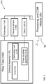
- FIG. 1 is a schematic block diagram of an exemplary flow tube spirometer 102 forming an integral part of system 100 according to the present invention for.
- System 100 comprises flow tube 102, where the flow tube is functionally associated with at least two sensors 104, 106, provided in the form of a pressure sensor 106 and a flow meter sensor 104, deflector assembly 110, a driver 108 for controlling the deflector assembly 110, and a processing and communication module 50.
- the flow meter may be provided in optional form as is known in the art. For example including but not limited to pneumotachograph, a Doppler flow meter, ultrasonic flow meter, filaments flow meter, the like or any combination thereof.
- processing and communication module 50 may be provided in the form of a computer, server, computer network, a mobile communication device, smartphone, processor, processing module, microprocessor, any device featuring a data processor and/or the like computational and communication, the like.
- module 50 may be linked and/or in wirelessly communication channels 52 with other processing centers, servers, computers or the like.
- module 50 may be linked electronically with a health care provider server, health management organization server, call center, emergency care service provider, physician, nurse, trained individual, the like or any combination thereof.
- Optionally communication channels 52 may be provided in optional forms for example including but not limited to wired, wireless, cellular, near field, contactless, optical, radio frequency, infrared the like or any combination thereof.
- module 50 is provided for processing and/or communicating data gathered by sensors and actuators, for example flow sensor 104, pressure sensor 106, driver 108 that are associated with flow tube 102.
- sensors and actuators for example flow sensor 104, pressure sensor 106, driver 108 that are associated with flow tube 102.
- module 50 provides for determining and/or inferring the lung FRC based on the data gathered and provided by flow tube 102.
- module 50 may be in communication with flow sensor 104, pressure sensor 106, and driver 108.
- module 50 may be utilized to activate and/or control the sensors 104,106 and actuators 108 associated with flow tube 102.
- module 50 may be utilized to control the frequency and activity of driver 108.
- driver 108 may be realized as an integrated member of module 50.
- Driver 108 may also be referred to as an actuator and/or motor that is provided to actuate and/or drive deflector assembly 110.
- driver 108 may be provided in the form of a motor, piezoelectric actuator, servo motor, or the like.
- driver 108 is provided for actuating and/or driving deflector assembly 110 via a driver coupling assembly 112 that is provided to couple axle 114 with driver 108.
- actuating axle 114 may be provided by driver assembly 108 directly or indirectly via coupling assembly 112.
- coupling assembly 112 may be provided in the form of an adaptor.
- coupling assembly 112 may be provided in the form of a converter, modulator or the like for example in the form of a gear box or the like provided to convert the actuation of motor 108 to movement by axle 114 that in turn depicts the movement of deflector leaf 116 within the lumen of flow tube 102.
- axle 114 may optionally provide for maneuvering deflector leaf about its axis about a planar rotational axis 118r about or a vertical axis.
- deflecting apparatus 110 is disposed within the lumen of a flow tube 102.
- Flow tube 102 may be provided as a substantially cylindrical tube 102.
- deflecting apparatus 110 is disposed along a radial cross-section of flow tube 102.
- flow tube 102 may be made of optional materials adept for medical use for and are biocompatible materials.
- flow tube 102 may for example be provided from polymers, super-elastic polymers, memory shaped polymers, hybrid polymers, or the like as is known in the art.
- flow tube 102 is a substantially cylindrical tube having a substantially open lumen 102L.
- Flow tube 102 has a length defined between a distal end 102d and a proximal end 102p.
- the substantially open lumen 102L is configured to allow air to flow from proximal end 102p to distal end 102d.
- Flow tube 102 has a wall 102w defined between an inner diameter 102i and an outer diameter 102o.
- flow tube 102 is associated with at least two sensors, preferably a flow sensor 104 and a pressure sensor 106.
- flow sensors 104 and pressure sensor 106 provide data relating to the air pressure and air flow of flowing air depicted by arrows 10 through lumen 102L.
- wall 102w may comprise at least two recesses or dedicated opening provided for receiving flow-meter (104) and a pressure sensor (106).
- Flow tube 102 comprises flow deflector apparatus 110 within lumen 102L.
- Flow deflector 110 provides for deflecting flowing air 10 along the length of tube 102 so as to enable the measurement of air flow and pressure with sensors 104, 106 respectively under variable conditions.
- apparatus 110 comprises actuator 112, axle 114, and deflecting leaf / non-occluding shutter 116, as previously described.
- Optionally deflecting apparatus 110 may be disposed along the length of tube 102 at a distance 102a defined between proximal end 102p and axle 114.
- tube 102 may provide for controlling the location of apparatus 110 by determining and controlling distance 102a.
- flow tube 102 may comprise at least one or more embedded channel (not shown) within wall 102w along the tube's length.
- embedded channel may facilitate for wiring and electronically coupling portion of deflection apparatus 110, flow-meter sensor 104, and/or pressure sensor 106 for coupling with processing module 50.
- apparatus 110 may be disposed within two parallel totally embedded channel (not shown) disposed within wall 102w along the length of tube 102.
- totally embedded channels may facilitate placing apparatus 110 at a controllable distance 102a within lumen 102L.
- axle 114 comprises a first end 114a disposed within wall 102w and a second end 114b extending through flow tube wall 102w, to associate with axle adaptor 112 that is in turn provided for coupling and/or associating with actuator 108.
- second end 114b may be adapted for associating with an actuator/driver (108) directly without adaptor 112.
- axle 114 is provided to drive non-occluding shutter leaf 116 within flow tube lumen (102L) in at least one direction, for example as in the rotational axis depicted by arrow 118r or in the vertical axis depicted by arrow 118v.
- Axle 114 is associated with a deflector leaf member 116 provided for deflecting airflow within the lumen of flow tube 102, wherein leaf 116 is characterized in that leaf 116 is configured not to occlude airflow through flow-tube lumen 102L therein to maintaining normal breathing physiology when a user breaths through flow-tube 102, according to the present invention.
- leaf 116 may be controllably manipulated with axle 114 to assume at least two positions within said flow tube lumen 102L, a first leaf position provided to maintain said flow-tube lumen substantially open, leading to nondeflected airflow 10, depicted in FIG. 2A-B , and a second leaf position provided to deflect airflow through said flow tube, depicted in FIG. 3A-B , leading to deflected air flow 12.
- Optionally deflecting leaf 116 that is characterized in that it is configured not to occlude airflow through flow-tube lumen 102L and therein to maintaining normal breathing physiology, is further configured to be a substantially flat leaf having a substantially circular profile configured to having a diameter that is to be up to about 50% of said flow tube diameter.
- leaf 116 may be configured to deflect airflow 10,12 within flow-tube lumen 102L wherein the surface area of leaf 116 configured to be substantially equivalent to up to about 50% the cross-sectional area the flow-tube.
- FIG.2A shows a cross section view of tube 102 along its length, showing leaf 116 in its small profile configuration that substantially allows for un-deflected airflow 10 to flow from proximal end 102p to distal end 102d.
- FIG. 2B shows a radial cross section view of tube 102, viewed from the proximal end 102p toward distal end 102d, showing that leaf 116 assumes a non-deflection configuration.
- FIG.3A shows a cross section view of tube 102 along its length, showing leaf 116 in its expanded profile configuration that substantially deflect airflow 12 to flow from proximal end 102p to distal end 102d, around leaf 116, while maintaining normal breathing physiology for the user (patient).
- FIG. 3B shows the radial cross section view of tube 102, viewed from the proximal end 102p toward distal end 102d, showing the leaf 116 assumes the expanded profile that deflects airflow through tube 102.
- Leaf 116 is configured not to takes up no more than 50% of the cross-sectional surface area of tube lumen 102L, therein deflected airflow 12 through the tube while allowing normal breathing physiology even when leaf 116 is in the expanded configuration.
- the leaf 116 may switch between configurations at a given rate.
- the leaf 116 switches positions at a frequency from about 2Hz up to about 10Hz.
- the leaf 116 switches positions at a frequency of up to about 15Hz.
- the leaf 116 switches positions at a frequency from about 1 Hz.
- leaf 116 may be switched between configurations according to physician determined intervals.
- leaf 116 may be switched between configurations according to randomly determined intervals.
- leaf 116 may be manually switched between configuration by a care giver, physician, nurse, trained individual, and/or a patient.
- leaf 116 may switch positions by remote control provided by module 50.
- leaf 116 may switch position according to a testing protocol that is individualized.
- leaf 116 may switch position according to a testing protocol that is determined based on a treatment protocol, the type of anomaly that is checked, disease state, the like or any combination thereof.
- the variation both in airflow and air pressure as measured with sensors 104 and 106 while the non-occluding leaf 116 is disposed in the low profile configuration ( FIG. 2A-B ) and the expanded configuration ( FIG. 3A-B ) is gathered by module 50 and for analysis.
- the resultant graphical representation of the changes in flow and pressure may be displayed to a user, printout, saved to a computer readable media, communicated to a higher processing center, communicated to a server, any combination thereof or the like.
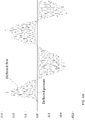
- FIG. 4A-D show graphical depiction of the measured parameters provided with flow tube 102 according to optional embodiments of the present invention.
- FIG. 4A shows the continuous graphical representation that shows the overall behavior of the changes in air flow and pressure provided with tube 102.
- the upper trace shows the fluctuations in deflected airflow through tube 102 while leaf 116 assumed different profiles.
- the lower trace shows the fluctuations in deflected air pressure through tube 102 while leaf assumed different portfolios.
- FIG. 4B shows a close up of the traces shown in FIG. 4A where the traces for changing airflow, upper trace, and changing pressure, lower trace, are more readily visible.
- FIG. 4C shows a close up of the traces shown in FIG. 4B where the traces for changing airflow, upper trace, and changing pressure, lower trace, are more readily visible.
- FIG. 4A-C show a sinusoidal trace depicting the fluctuations in air flow and air pressure through the flow tube under different configurations of non-occluding leaf 116.
- the sinusoidal trace provides for determining the changes in volume ( ⁇ V, as shown in the shaded area), and changes in pressure ( ⁇ P) by determining the area below the curve, between peak and tough, for example as shown in FIG. 4C .
- FRC Functional Residual Capacity
- BP base barometric pressure (atmospheric pressure).
- the resultant FRC may be displayed in graphical form for example as shown in FIG. 4D .
- Other lung volume parameters may be inferred, as is known in the art.
- FIG. 5 shows a flowchart depicting the method for determining FRC with the spirometer 100 of the present invention comprising a non-occluding spirometer leaf shutter 116.
- a patient is breaths through flow tube 102 when leaf 116 is in the low profile configuration, allowing air flow through tube 102 as depicted by un-deflected airflow 10.
- Module 50 is preferably utilized to store data sensed with sensors 104, 106.
- leaf 116 configuration is changed from low profile, FIG. 2A-B , to expanded profile, FIG. 3A-B , optionally by utilizing actuator 112 to rotate axle 114 along radial axis 118r with lumen 102L.
- flow tube 102 now having a deflected air flow 12 with the expanded configuration of leaf 116 deployed within lumen 102L, allows sensors 104, 106 to sense while preferably module 50 monitors the changes.
- the flow tube 102 may be revert to stages 500 and continue the detection process until the end of the measuring protocol.
- stage 503 the previously recorded data is analyzed with module 50 to determine the lung FRC.
- the results may be displayed, communicated and/or provided as an output to a user or a computer for further processing.
- the results may be communicated via communication channels 52 to a health care professional, to a user, to an Emergency call center, or the like.
- the results may be communicated to trigger an alarm state when compared to threshold levels.
- processing and communication module 50 provides for controlling the timing of stages 500-503.
Claims (16)
- Dispositif à tube d'écoulement prévu pour déterminer la capacité résiduelle fonctionnelle du poumon (FRC), le dispositif comprenant :a) un tube d'écoulement (102) ayant une longueur définie entre une extrémité distale (102d) et une extrémité proximale (102p), ayant une lumière essentiellement ouverte (102L) configurée pour permettre à l'air de s'écouler de ladite extrémité proximale (102p) à ladite extrémité distale (102d) ; ledit tube d'écoulement ayant une paroi définie entre un diamètre intérieur (102i) et un diamètre extérieur (102o) ;b) un premier évidement disposé à l'intérieur de la paroi prévue pour recevoir un débitmètre (104) et un deuxième évidement disposé à l'intérieur de la paroi prévue pour recevoir un capteur de pression (106) ;c) ledit tube d'écoulement configuré pour s'associer avec un dispositif déflecteur d'écoulement (110) comprenant :i) un arbre (114) disposé à travers le diamètre de ladite lumière (102L) à une distance (114d) de ladite extrémité proximale (102p), ledit arbre (114) ayant une première extrémité (114a) disposée à l'intérieur de ladite paroi de tube d'écoulement (102w) et une deuxième extrémité (114b) s'étendant à travers et transcendant ladite paroi de tube d'écoulement (102w), ladite deuxième extrémité (114b) étant conçue pour s'associer avec un dispositif d'entraînement de déflecteur (108) disposé à l'extérieur dudit tube d'écoulement ;ii) dans lequel ledit dispositif d'entraînement de déflecteur (112) est adapté pour entraîner ledit arbre (114) à l'intérieur de ladite lumière de tube d'écoulement (102L) dans au moins une direction ;iii) ledit arbre (114)) associé à un élément de feuille déflectrice (116) prévu pour dévier le flux d'air dans ledit tube d'écoulement (102) caractérisé en ce que ladite feuille (116) est configurée pour ne pas obstruer le flux d'air à travers ledit tube d'écoulement (102) et y s'écouler à travers ledit tube de manière à maintenir une physiologie normale de la respiration le long dudit tube d'écoulement (102) ; et dans lequel ledit élément de feuille déflectrice (116) peut être manipulé par commande autour dudit arbre (114) pour prendre au moins deux positions non occlusives dans ledit tube d'écoulement (102), une première position de feuille étant prévue pour maintenir ladite lumière de tube d'écoulement essentiellement ouverte et une deuxième position de feuille prévue pour dévier le flux d'air à travers ledit tube d'écoulement.
- Dispositif selon la revendication 1, dans lequel ladite feuille déflectrice (116) est configurée pour dévier le flux d'air à l'intérieur dudit tube d'écoulement dans lequel la surface de ladite feuille équivaut jusqu'à environ 50% de la coupe transversale dudit tube d'écoulement.
- Dispositif selon la revendication 1, dans lequel ladite feuille déflectrice (116) est configurée pour être une feuille essentiellement plate ayant un profil essentiellement circulaire configuré pour avoir un diamètre qui doit s'élever jusqu'à environ 50% dudit diamètre du tube d'écoulement.
- Dispositif selon la revendication 1 ou 2, dans lequel ladite feuille (116) est configurée avec une forme géométrique plane, ladite forme géométrique étant choisie dans le groupe consistant en : ellipsoïde, elliptique, circulaire, ovoïde, annulaire, discoïde, polyédrique ayant n côtés où n est au moins 3, trapézoïdale, quadrilatère, carré et triangulaire.
- Tube d'écoulement selon la revendication 1, dans lequel ladite paroi comprend au moins un canal encastré le long de la longueur de ladite paroi de tube (102w).
- Tube d'écoulement selon la revendication 5, dans lequel ledit canal encastré facilite l'association dudit débitmètre, dudit capteur de pression et dudit dispositif déflecteur d'écoulement avec un dispositif de traitement.
- Tube d'écoulement selon la revendication 1, comprenant en outre au moins un ou plusieurs dispositifs déflecteurs auxiliaires (110).
- Tube d'écoulement selon la revendication 1, dans lequel ledit diamètre intérieur présente au moins l'un des profilés suivants le long de la longueur de ladite lumière ouverte (102L): profilé de diamètre fluctuant, diamètre décroissant, diamètre augmentant, profilé de sablier, profilé semblant à des ondes ou diamètre changeant.
- Dispositif selon la revendication 1, dans lequel ledit dispositif d'entraînement (112) entraîne ladite feuille déflectrice (116) dans au moins un axe autour dudit arbre (114) dans ladite lumière (102L), sélectionné parmi un axe de rotation (118r) et un axe vertical (118v).
- Dispositif selon la revendication 1, dans lequel ledit arbre (114) est adapté pour permettre à la fois le mouvement de rotation (118r) et le mouvement vertical (118v) de ladite feuille (116) à l'intérieur de ladite lumière (102L).
- Dispositif selon la revendication 1, dans lequel ledit dispositif déflecteur est prévu pour faire tourner ladite feuille à une fréquence jusqu'à 15Hz.
- Dispositif selon l'une quelconque des revendications précédentes, fourni à partir d'un matériau multi-usage qui peut être stérilisé, ou à partir d'un matériau jetable à usage unique.
- Dispositif selon la revendication 1, dans lequel ledit débitmètre et ledit capteur de pression sont encastrés dans ladite paroi de tube d'écoulement (102w) directement ou dans un canal entièrement encastré à l'intérieur de ladite paroi de tube (102w).
- Dispositif selon la revendication 1, dans lequel ladite feuille déflectrice (116) est configurée pour prendre au moins deux configurations de forme de profil ou plus, ladite feuille déflectrice (116) est fournie à partir d'au moins l'un parmi les matériaux suivant: matériau à mémoire de forme, matériau super élastique, polymère super élastique, alliage super élastique et plastique super élastique.
- Procédé pour déterminer la capacité résiduelle fonctionnelle du poumon (FRC), en utilisant le dispositif selon la revendication 1, le procédé comprenant les étapes consistant à :a) mesurer le flux d'air et la pression à travers ledit tube d'écoulement dans lequel ladite feuille déflectrice est dans une première position pour une première trame temporelle ;b) activer ledit dispositif d'entraînement de déflecteur (108) et ledit dispositif déflecteur (110) pour changer la position de ladite feuille (116) à partir de ladite première position vers une deuxième position ;c) mesurer le flux d'air et la pression à travers ledit tube d'écoulement dans lequel ladite feuille déflectrice est dans une deuxième position pour une deuxième trame temporelle ;d) analyser ledit ensemble de mesures pour déterminer le changement en volume et le changement en pression entre ledit ensemble de mesures ;e) déterminer le rapport entre le changement en volume et le changement en pression pour en dériver la FRC pulmonaire.
- Dispositif selon la revendication 1, dans lequel ledit tube d'écoulement (102) est associé à un module de traitement (50) configuré pour traiter des données reçues dudit débitmètre (104), dudit capteur de pression (106) et dudit dispositif déflecteur (110).
Applications Claiming Priority (2)
| Application Number | Priority Date | Filing Date | Title |
|---|---|---|---|
| US201361867489P | 2013-08-19 | 2013-08-19 | |
| PCT/IL2014/050728 WO2015025316A1 (fr) | 2013-08-19 | 2014-08-13 | Système et procédé de spiromètre pour déterminer une capacité résiduelle fonctionnelle (frc) des poumons ayant un obturateur non occlusif |
Publications (3)
| Publication Number | Publication Date |
|---|---|
| EP3035847A1 EP3035847A1 (fr) | 2016-06-29 |
| EP3035847A4 EP3035847A4 (fr) | 2017-05-10 |
| EP3035847B1 true EP3035847B1 (fr) | 2018-02-14 |
Family
ID=52483146
Family Applications (1)
| Application Number | Title | Priority Date | Filing Date |
|---|---|---|---|
| EP14837494.5A Expired - Fee Related EP3035847B1 (fr) | 2013-08-19 | 2014-08-13 | Système et procédé de spiromètre pour déterminer une capacité résiduelle fonctionnelle (frc) des poumons ayant un obturateur non occlusif |
Country Status (5)
| Country | Link |
|---|---|
| US (1) | US10327668B2 (fr) |
| EP (1) | EP3035847B1 (fr) |
| CN (1) | CN105658141B (fr) |
| ES (1) | ES2665315T3 (fr) |
| WO (1) | WO2015025316A1 (fr) |
Families Citing this family (6)
| Publication number | Priority date | Publication date | Assignee | Title |
|---|---|---|---|---|
| DK3195160T3 (da) * | 2014-09-16 | 2020-08-17 | Medituner Ab | Computerstyret doseringssystem |
| US20170361041A1 (en) * | 2016-06-16 | 2017-12-21 | Loewenstein Medical Technology S.A. | Respirator for apap respiration using oscillatory pressure |
| IL250970B (en) * | 2017-03-06 | 2018-05-31 | Technopulm Ltd | Device and method for evaluating lung function characteristics |
| GB201809558D0 (en) * | 2018-06-09 | 2018-07-25 | Smiths Medical International Ltd | Spirometer apparatus |
| US20210290101A1 (en) * | 2018-07-14 | 2021-09-23 | Arete Medical Technologies Ltd | Respiratory diagnostic tool and method |
| GB2576136B (en) * | 2018-07-14 | 2022-08-24 | Arete Medical Tech Ltd | Multi-test respiratory diagnostic device |
Family Cites Families (20)
| Publication number | Priority date | Publication date | Assignee | Title |
|---|---|---|---|---|
| US4220161A (en) | 1975-04-18 | 1980-09-02 | Berlin Howard M | Perturbation device for the measurement of airway resistance |
| GB8920499D0 (en) | 1989-09-11 | 1989-10-25 | Micro Medical Ltd | Apparatus for measuring airway resistance |
| US5261397A (en) | 1991-05-10 | 1993-11-16 | The Children's Hospital Of Philadelphia | Methods and apparatus for measuring infant lung function and providing respiratory system therapy |
| US5584300A (en) | 1995-08-24 | 1996-12-17 | Arocom Ltd. | Measurement of lung air capacity |
| DE59712025D1 (de) * | 1996-09-13 | 2004-11-25 | Schiller Ag | Vorrichtung und Verfahren zum Messen des Atemwegwiderstandes |
| US5857459A (en) | 1997-02-04 | 1999-01-12 | Medical Graphics Corporation | Boxless measurement of thoracic gas volume |
| AUPO830097A0 (en) | 1997-07-29 | 1997-08-21 | University Of Queensland, The | A plethysmograph |
| US6066101A (en) | 1998-04-20 | 2000-05-23 | University Of Maryland | Airflow perturbation device and method for measuring respiratory resistance |
| US6183423B1 (en) | 1998-05-14 | 2001-02-06 | Respironics, Inc. | Breathing disorder prescreening device and method |
| US20050274049A1 (en) * | 2003-08-16 | 2005-12-15 | Schmidt Paula K | Shadowbox greeting cards |
| EP1895908A4 (fr) | 2005-06-10 | 2009-12-09 | Telethon Inst For Child Health | Procede de mesure d'une impedance acoustique d'un systeme respiratoire et de diagnostic d'une maladie ou d'un trouble respiratoire ou de surveillance d'un traitement associe |
| US7681574B2 (en) | 2005-12-22 | 2010-03-23 | General Electric Company | Method and apparatus for determining functional residual capacity of the lungs |
| EP2190351B1 (fr) * | 2007-07-26 | 2019-03-20 | Pulmone Advanced Medical Devices, Ltd. | Procédé de mesure de volumes pulmonaires |
| US8657757B2 (en) | 2007-07-26 | 2014-02-25 | Pulmone Advanced Medical Devices, Ltd. | System and methods for the measurement of lung volumes |
| DE102008007153B4 (de) * | 2008-01-31 | 2010-06-02 | Voith Patent Gmbh | Längenverstellbare Welle |
| CA2719813C (fr) * | 2008-03-28 | 2019-03-12 | Orion Diagnostica Oy | Dispositif d'echantillonnage et de distribution |
| EP2381844A4 (fr) | 2009-01-28 | 2015-06-03 | Pulmone Advanced Medical Devices Ltd | Procédés et dispositifs de détermination de mesures pulmonaires |
| EP2233167B1 (fr) * | 2009-03-27 | 2016-07-20 | General Electric Company | Agencement pour améliorer la précision de la mesure de pression et capteur de flux |
| US8418549B2 (en) * | 2011-01-31 | 2013-04-16 | Honeywell International Inc. | Flow sensor assembly with integral bypass channel |
| WO2012004794A1 (fr) | 2010-07-06 | 2012-01-12 | Pulmone Advanced Medical Devices, Ltd. | Procédés et appareil de mesure de paramètres pulmonaires |
-
2014
- 2014-08-13 US US14/913,009 patent/US10327668B2/en not_active Expired - Fee Related
- 2014-08-13 ES ES14837494.5T patent/ES2665315T3/es active Active
- 2014-08-13 WO PCT/IL2014/050728 patent/WO2015025316A1/fr active Application Filing
- 2014-08-13 CN CN201480057411.2A patent/CN105658141B/zh not_active Expired - Fee Related
- 2014-08-13 EP EP14837494.5A patent/EP3035847B1/fr not_active Expired - Fee Related
Non-Patent Citations (1)
| Title |
|---|
| None * |
Also Published As
| Publication number | Publication date |
|---|---|
| ES2665315T3 (es) | 2018-04-25 |
| CN105658141B (zh) | 2018-11-20 |
| CN105658141A (zh) | 2016-06-08 |
| EP3035847A1 (fr) | 2016-06-29 |
| WO2015025316A1 (fr) | 2015-02-26 |
| US10327668B2 (en) | 2019-06-25 |
| EP3035847A4 (fr) | 2017-05-10 |
| US20160198980A1 (en) | 2016-07-14 |
Similar Documents
| Publication | Publication Date | Title |
|---|---|---|
| EP3035847B1 (fr) | Système et procédé de spiromètre pour déterminer une capacité résiduelle fonctionnelle (frc) des poumons ayant un obturateur non occlusif | |
| US20220110541A1 (en) | Methods Of Non-Invasively Determining Blood Oxygen Level And Related Pulmonary Gas Exchange Information | |
| US10357209B2 (en) | Bidirectional physiological information display | |
| EP1631340B1 (fr) | Dispositif portatif de diagnostic respiratoire | |
| US20160150998A1 (en) | Methods and devices for determining pulmonary measurement | |
| US20160106341A1 (en) | Determining respiratory parameters | |
| JP2019500084A (ja) | 生理的パラメータを監視するための装置および方法 | |
| EP2306896B1 (fr) | Systèmes non invasifs pour évaluer la pression de remplissage cardiaque | |
| WO2013049837A1 (fr) | Systèmes de mesure de sonde ombilicale | |
| US20140121478A1 (en) | Umbilical probe measurement systems | |
| Tipparaju et al. | Respiration pattern recognition by wearable mask device | |
| US20140100470A1 (en) | Digital inspirometer system | |
| US20140235959A1 (en) | Methods and algorithms for supervisory closed-loop determination of optimized scheduling of ventilator weaning trials | |
| US7678060B1 (en) | Method of monitoring a state of health, and a wellness/emotional state monitor implementing the method | |
| EP2706907B1 (fr) | Processus automatisé à utiliser dans l'évaluation de la pression de remplissage cardiaque de manière non invasive | |
| US20240099583A1 (en) | Methods and Systems for Patient Parameter Fusion and Feedback | |
| JP5596551B2 (ja) | 人工呼吸装置および/または麻酔装置 | |
| JP2023504275A (ja) | 代謝モニタリングのためのシステム及び方法 | |
| EP3671760A1 (fr) | Système et procédé permettant de prédire une exacerbation | |
| Wankum et al. | Validation of a noninvasive blood pressure monitoring device in normotensive and hypertensive pediatric intensive care patients | |
| EP4079221A1 (fr) | Système d'identification de l'état d'un utilisateur | |
| Kanna et al. | Computational Spirometer Using Arduino Nano Application: Smart Spirometer Module | |
| US20150005591A1 (en) | Tissue to end tidal co2 monitor | |
| Swamy et al. | Non Invasive Device to Measure and Monitor Lung Capacity | |
| KR20220125988A (ko) | 심탄도와 인공지능 기술을 이용한 혈압측정장치 |
Legal Events
| Date | Code | Title | Description |
|---|---|---|---|
| PUAI | Public reference made under article 153(3) epc to a published international application that has entered the european phase |
Free format text: ORIGINAL CODE: 0009012 |
|
| 17P | Request for examination filed |
Effective date: 20160317 |
|
| AK | Designated contracting states |
Kind code of ref document: A1 Designated state(s): AL AT BE BG CH CY CZ DE DK EE ES FI FR GB GR HR HU IE IS IT LI LT LU LV MC MK MT NL NO PL PT RO RS SE SI SK SM TR |
|
| AX | Request for extension of the european patent |
Extension state: BA ME |
|
| RIN1 | Information on inventor provided before grant (corrected) |
Inventor name: ITZKOVITCH, HANAN Inventor name: TCHERNICHOVSKY, LEONID Inventor name: GAIDES, MARK |
|
| DAX | Request for extension of the european patent (deleted) | ||
| A4 | Supplementary search report drawn up and despatched |
Effective date: 20170410 |
|
| RIC1 | Information provided on ipc code assigned before grant |
Ipc: A61B 5/091 20060101ALI20170404BHEP Ipc: G01F 3/20 20060101ALI20170404BHEP Ipc: G01F 3/24 20060101ALI20170404BHEP Ipc: A61B 5/087 20060101AFI20170404BHEP |
|
| GRAP | Despatch of communication of intention to grant a patent |
Free format text: ORIGINAL CODE: EPIDOSNIGR1 |
|
| RIC1 | Information provided on ipc code assigned before grant |
Ipc: G01F 3/24 20060101ALI20170814BHEP Ipc: A61B 5/091 20060101ALI20170814BHEP Ipc: G01F 3/20 20060101ALI20170814BHEP Ipc: A61B 5/087 20060101AFI20170814BHEP |
|
| INTG | Intention to grant announced |
Effective date: 20170906 |
|
| GRAS | Grant fee paid |
Free format text: ORIGINAL CODE: EPIDOSNIGR3 |
|
| GRAA | (expected) grant |
Free format text: ORIGINAL CODE: 0009210 |
|
| AK | Designated contracting states |
Kind code of ref document: B1 Designated state(s): AL AT BE BG CH CY CZ DE DK EE ES FI FR GB GR HR HU IE IS IT LI LT LU LV MC MK MT NL NO PL PT RO RS SE SI SK SM TR |
|
| REG | Reference to a national code |
Ref country code: GB Ref legal event code: FG4D |
|
| REG | Reference to a national code |
Ref country code: CH Ref legal event code: EP |
|
| REG | Reference to a national code |
Ref country code: IE Ref legal event code: FG4D |
|
| REG | Reference to a national code |
Ref country code: DE Ref legal event code: R096 Ref document number: 602014021056 Country of ref document: DE Ref country code: AT Ref legal event code: REF Ref document number: 969345 Country of ref document: AT Kind code of ref document: T Effective date: 20180315 |
|
| REG | Reference to a national code |
Ref country code: ES Ref legal event code: FG2A Ref document number: 2665315 Country of ref document: ES Kind code of ref document: T3 Effective date: 20180425 |
|
| REG | Reference to a national code |
Ref country code: NL Ref legal event code: FP |
|
| REG | Reference to a national code |
Ref country code: CH Ref legal event code: NV Representative=s name: SERVOPATENT GMBH, CH |
|
| REG | Reference to a national code |
Ref country code: AT Ref legal event code: MK05 Ref document number: 969345 Country of ref document: AT Kind code of ref document: T Effective date: 20180214 |
|
| PG25 | Lapsed in a contracting state [announced via postgrant information from national office to epo] |
Ref country code: FI Free format text: LAPSE BECAUSE OF FAILURE TO SUBMIT A TRANSLATION OF THE DESCRIPTION OR TO PAY THE FEE WITHIN THE PRESCRIBED TIME-LIMIT Effective date: 20180214 Ref country code: CY Free format text: LAPSE BECAUSE OF FAILURE TO SUBMIT A TRANSLATION OF THE DESCRIPTION OR TO PAY THE FEE WITHIN THE PRESCRIBED TIME-LIMIT Effective date: 20180214 Ref country code: LT Free format text: LAPSE BECAUSE OF FAILURE TO SUBMIT A TRANSLATION OF THE DESCRIPTION OR TO PAY THE FEE WITHIN THE PRESCRIBED TIME-LIMIT Effective date: 20180214 Ref country code: NO Free format text: LAPSE BECAUSE OF FAILURE TO SUBMIT A TRANSLATION OF THE DESCRIPTION OR TO PAY THE FEE WITHIN THE PRESCRIBED TIME-LIMIT Effective date: 20180514 Ref country code: HR Free format text: LAPSE BECAUSE OF FAILURE TO SUBMIT A TRANSLATION OF THE DESCRIPTION OR TO PAY THE FEE WITHIN THE PRESCRIBED TIME-LIMIT Effective date: 20180214 |
|
| REG | Reference to a national code |
Ref country code: FR Ref legal event code: PLFP Year of fee payment: 5 |
|
| PG25 | Lapsed in a contracting state [announced via postgrant information from national office to epo] |
Ref country code: BG Free format text: LAPSE BECAUSE OF FAILURE TO SUBMIT A TRANSLATION OF THE DESCRIPTION OR TO PAY THE FEE WITHIN THE PRESCRIBED TIME-LIMIT Effective date: 20180514 Ref country code: AT Free format text: LAPSE BECAUSE OF FAILURE TO SUBMIT A TRANSLATION OF THE DESCRIPTION OR TO PAY THE FEE WITHIN THE PRESCRIBED TIME-LIMIT Effective date: 20180214 Ref country code: LV Free format text: LAPSE BECAUSE OF FAILURE TO SUBMIT A TRANSLATION OF THE DESCRIPTION OR TO PAY THE FEE WITHIN THE PRESCRIBED TIME-LIMIT Effective date: 20180214 Ref country code: SE Free format text: LAPSE BECAUSE OF FAILURE TO SUBMIT A TRANSLATION OF THE DESCRIPTION OR TO PAY THE FEE WITHIN THE PRESCRIBED TIME-LIMIT Effective date: 20180214 Ref country code: RS Free format text: LAPSE BECAUSE OF FAILURE TO SUBMIT A TRANSLATION OF THE DESCRIPTION OR TO PAY THE FEE WITHIN THE PRESCRIBED TIME-LIMIT Effective date: 20180214 Ref country code: GR Free format text: LAPSE BECAUSE OF FAILURE TO SUBMIT A TRANSLATION OF THE DESCRIPTION OR TO PAY THE FEE WITHIN THE PRESCRIBED TIME-LIMIT Effective date: 20180515 |
|
| PG25 | Lapsed in a contracting state [announced via postgrant information from national office to epo] |
Ref country code: PL Free format text: LAPSE BECAUSE OF FAILURE TO SUBMIT A TRANSLATION OF THE DESCRIPTION OR TO PAY THE FEE WITHIN THE PRESCRIBED TIME-LIMIT Effective date: 20180214 Ref country code: EE Free format text: LAPSE BECAUSE OF FAILURE TO SUBMIT A TRANSLATION OF THE DESCRIPTION OR TO PAY THE FEE WITHIN THE PRESCRIBED TIME-LIMIT Effective date: 20180214 Ref country code: RO Free format text: LAPSE BECAUSE OF FAILURE TO SUBMIT A TRANSLATION OF THE DESCRIPTION OR TO PAY THE FEE WITHIN THE PRESCRIBED TIME-LIMIT Effective date: 20180214 Ref country code: AL Free format text: LAPSE BECAUSE OF FAILURE TO SUBMIT A TRANSLATION OF THE DESCRIPTION OR TO PAY THE FEE WITHIN THE PRESCRIBED TIME-LIMIT Effective date: 20180214 |
|
| PGFP | Annual fee paid to national office [announced via postgrant information from national office to epo] |
Ref country code: IT Payment date: 20180823 Year of fee payment: 5 Ref country code: NL Payment date: 20180824 Year of fee payment: 5 Ref country code: FR Payment date: 20180824 Year of fee payment: 5 Ref country code: ES Payment date: 20180926 Year of fee payment: 5 |
|
| REG | Reference to a national code |
Ref country code: DE Ref legal event code: R097 Ref document number: 602014021056 Country of ref document: DE |
|
| PG25 | Lapsed in a contracting state [announced via postgrant information from national office to epo] |
Ref country code: DK Free format text: LAPSE BECAUSE OF FAILURE TO SUBMIT A TRANSLATION OF THE DESCRIPTION OR TO PAY THE FEE WITHIN THE PRESCRIBED TIME-LIMIT Effective date: 20180214 Ref country code: SM Free format text: LAPSE BECAUSE OF FAILURE TO SUBMIT A TRANSLATION OF THE DESCRIPTION OR TO PAY THE FEE WITHIN THE PRESCRIBED TIME-LIMIT Effective date: 20180214 Ref country code: SK Free format text: LAPSE BECAUSE OF FAILURE TO SUBMIT A TRANSLATION OF THE DESCRIPTION OR TO PAY THE FEE WITHIN THE PRESCRIBED TIME-LIMIT Effective date: 20180214 Ref country code: CZ Free format text: LAPSE BECAUSE OF FAILURE TO SUBMIT A TRANSLATION OF THE DESCRIPTION OR TO PAY THE FEE WITHIN THE PRESCRIBED TIME-LIMIT Effective date: 20180214 |
|
| PGFP | Annual fee paid to national office [announced via postgrant information from national office to epo] |
Ref country code: CH Payment date: 20180824 Year of fee payment: 5 Ref country code: GB Payment date: 20180831 Year of fee payment: 5 |
|
| PLBE | No opposition filed within time limit |
Free format text: ORIGINAL CODE: 0009261 |
|
| STAA | Information on the status of an ep patent application or granted ep patent |
Free format text: STATUS: NO OPPOSITION FILED WITHIN TIME LIMIT |
|
| 26N | No opposition filed |
Effective date: 20181115 |
|
| PGFP | Annual fee paid to national office [announced via postgrant information from national office to epo] |
Ref country code: DE Payment date: 20181031 Year of fee payment: 5 |
|
| PG25 | Lapsed in a contracting state [announced via postgrant information from national office to epo] |
Ref country code: SI Free format text: LAPSE BECAUSE OF FAILURE TO SUBMIT A TRANSLATION OF THE DESCRIPTION OR TO PAY THE FEE WITHIN THE PRESCRIBED TIME-LIMIT Effective date: 20180214 |
|
| PG25 | Lapsed in a contracting state [announced via postgrant information from national office to epo] |
Ref country code: MC Free format text: LAPSE BECAUSE OF FAILURE TO SUBMIT A TRANSLATION OF THE DESCRIPTION OR TO PAY THE FEE WITHIN THE PRESCRIBED TIME-LIMIT Effective date: 20180214 |
|
| PG25 | Lapsed in a contracting state [announced via postgrant information from national office to epo] |
Ref country code: LU Free format text: LAPSE BECAUSE OF NON-PAYMENT OF DUE FEES Effective date: 20180813 |
|
| REG | Reference to a national code |
Ref country code: BE Ref legal event code: MM Effective date: 20180831 |
|
| REG | Reference to a national code |
Ref country code: IE Ref legal event code: MM4A |
|
| PG25 | Lapsed in a contracting state [announced via postgrant information from national office to epo] |
Ref country code: IE Free format text: LAPSE BECAUSE OF NON-PAYMENT OF DUE FEES Effective date: 20180813 |
|
| PG25 | Lapsed in a contracting state [announced via postgrant information from national office to epo] |
Ref country code: BE Free format text: LAPSE BECAUSE OF NON-PAYMENT OF DUE FEES Effective date: 20180831 |
|
| PG25 | Lapsed in a contracting state [announced via postgrant information from national office to epo] |
Ref country code: MT Free format text: LAPSE BECAUSE OF NON-PAYMENT OF DUE FEES Effective date: 20180813 |
|
| REG | Reference to a national code |
Ref country code: DE Ref legal event code: R119 Ref document number: 602014021056 Country of ref document: DE |
|
| PG25 | Lapsed in a contracting state [announced via postgrant information from national office to epo] |
Ref country code: TR Free format text: LAPSE BECAUSE OF FAILURE TO SUBMIT A TRANSLATION OF THE DESCRIPTION OR TO PAY THE FEE WITHIN THE PRESCRIBED TIME-LIMIT Effective date: 20180214 |
|
| REG | Reference to a national code |
Ref country code: NL Ref legal event code: MM Effective date: 20190901 |
|
| GBPC | Gb: european patent ceased through non-payment of renewal fee |
Effective date: 20190813 |
|
| PG25 | Lapsed in a contracting state [announced via postgrant information from national office to epo] |
Ref country code: CH Free format text: LAPSE BECAUSE OF NON-PAYMENT OF DUE FEES Effective date: 20190831 Ref country code: LI Free format text: LAPSE BECAUSE OF NON-PAYMENT OF DUE FEES Effective date: 20190831 Ref country code: PT Free format text: LAPSE BECAUSE OF FAILURE TO SUBMIT A TRANSLATION OF THE DESCRIPTION OR TO PAY THE FEE WITHIN THE PRESCRIBED TIME-LIMIT Effective date: 20180214 |
|
| PG25 | Lapsed in a contracting state [announced via postgrant information from national office to epo] |
Ref country code: MK Free format text: LAPSE BECAUSE OF NON-PAYMENT OF DUE FEES Effective date: 20180214 Ref country code: HU Free format text: LAPSE BECAUSE OF FAILURE TO SUBMIT A TRANSLATION OF THE DESCRIPTION OR TO PAY THE FEE WITHIN THE PRESCRIBED TIME-LIMIT; INVALID AB INITIO Effective date: 20140813 |
|
| PG25 | Lapsed in a contracting state [announced via postgrant information from national office to epo] |
Ref country code: DE Free format text: LAPSE BECAUSE OF NON-PAYMENT OF DUE FEES Effective date: 20200303 Ref country code: FR Free format text: LAPSE BECAUSE OF NON-PAYMENT OF DUE FEES Effective date: 20190831 Ref country code: NL Free format text: LAPSE BECAUSE OF NON-PAYMENT OF DUE FEES Effective date: 20190901 Ref country code: IS Free format text: LAPSE BECAUSE OF FAILURE TO SUBMIT A TRANSLATION OF THE DESCRIPTION OR TO PAY THE FEE WITHIN THE PRESCRIBED TIME-LIMIT Effective date: 20180614 |
|
| PG25 | Lapsed in a contracting state [announced via postgrant information from national office to epo] |
Ref country code: IT Free format text: LAPSE BECAUSE OF NON-PAYMENT OF DUE FEES Effective date: 20190813 Ref country code: GB Free format text: LAPSE BECAUSE OF NON-PAYMENT OF DUE FEES Effective date: 20190813 |
|
| REG | Reference to a national code |
Ref country code: ES Ref legal event code: FD2A Effective date: 20210105 |
|
| PG25 | Lapsed in a contracting state [announced via postgrant information from national office to epo] |
Ref country code: ES Free format text: LAPSE BECAUSE OF NON-PAYMENT OF DUE FEES Effective date: 20190814 |