EP3035357B1 - Modular electromechanical switch element - Google Patents
Modular electromechanical switch element Download PDFInfo
- Publication number
- EP3035357B1 EP3035357B1 EP14199290.9A EP14199290A EP3035357B1 EP 3035357 B1 EP3035357 B1 EP 3035357B1 EP 14199290 A EP14199290 A EP 14199290A EP 3035357 B1 EP3035357 B1 EP 3035357B1
- Authority
- EP
- European Patent Office
- Prior art keywords
- unit
- switching device
- electromechanical switching
- electromechanical
- switching
- Prior art date
- Legal status (The legal status is an assumption and is not a legal conclusion. Google has not performed a legal analysis and makes no representation as to the accuracy of the status listed.)
- Active
Links
- 230000008878 coupling Effects 0.000 claims description 37
- 238000010168 coupling process Methods 0.000 claims description 37
- 238000005859 coupling reaction Methods 0.000 claims description 37
- 230000004913 activation Effects 0.000 claims description 10
- 238000013461 design Methods 0.000 claims description 3
- 238000003780 insertion Methods 0.000 claims description 3
- 230000037431 insertion Effects 0.000 claims description 3
- 238000004519 manufacturing process Methods 0.000 description 4
- 238000010276 construction Methods 0.000 description 3
- 238000011161 development Methods 0.000 description 3
- 230000018109 developmental process Effects 0.000 description 3
- 230000004044 response Effects 0.000 description 3
- 229910000831 Steel Inorganic materials 0.000 description 1
- 230000000712 assembly Effects 0.000 description 1
- 238000000429 assembly Methods 0.000 description 1
- 239000002131 composite material Substances 0.000 description 1
- 230000009849 deactivation Effects 0.000 description 1
- 230000001419 dependent effect Effects 0.000 description 1
- 238000010616 electrical installation Methods 0.000 description 1
- 238000010292 electrical insulation Methods 0.000 description 1
- 230000002349 favourable effect Effects 0.000 description 1
- 210000003746 feather Anatomy 0.000 description 1
- 238000009434 installation Methods 0.000 description 1
- 230000013011 mating Effects 0.000 description 1
- 230000005226 mechanical processes and functions Effects 0.000 description 1
- 239000007769 metal material Substances 0.000 description 1
- 238000000034 method Methods 0.000 description 1
- 230000008569 process Effects 0.000 description 1
- 239000010959 steel Substances 0.000 description 1
- 238000012360 testing method Methods 0.000 description 1
Images


Classifications
-
- H—ELECTRICITY
- H01—ELECTRIC ELEMENTS
- H01H—ELECTRIC SWITCHES; RELAYS; SELECTORS; EMERGENCY PROTECTIVE DEVICES
- H01H19/00—Switches operated by an operating part which is rotatable about a longitudinal axis thereof and which is acted upon directly by a solid body external to the switch, e.g. by a hand
- H01H19/02—Details
- H01H19/10—Movable parts; Contacts mounted thereon
- H01H19/14—Operating parts, e.g. turn knob
-
- H—ELECTRICITY
- H01—ELECTRIC ELEMENTS
- H01H—ELECTRIC SWITCHES; RELAYS; SELECTORS; EMERGENCY PROTECTIVE DEVICES
- H01H27/00—Switches operated by a removable member, e.g. key, plug or plate; Switches operated by setting members according to a single predetermined combination out of several possible settings
- H01H27/06—Key inserted and then turned to effect operation of the switch
-
- H—ELECTRICITY
- H01—ELECTRIC ELEMENTS
- H01H—ELECTRIC SWITCHES; RELAYS; SELECTORS; EMERGENCY PROTECTIVE DEVICES
- H01H19/00—Switches operated by an operating part which is rotatable about a longitudinal axis thereof and which is acted upon directly by a solid body external to the switch, e.g. by a hand
- H01H19/02—Details
- H01H19/03—Means for limiting the angle of rotation of the operating part
-
- H—ELECTRICITY
- H01—ELECTRIC ELEMENTS
- H01H—ELECTRIC SWITCHES; RELAYS; SELECTORS; EMERGENCY PROTECTIVE DEVICES
- H01H19/00—Switches operated by an operating part which is rotatable about a longitudinal axis thereof and which is acted upon directly by a solid body external to the switch, e.g. by a hand
- H01H19/54—Switches operated by an operating part which is rotatable about a longitudinal axis thereof and which is acted upon directly by a solid body external to the switch, e.g. by a hand the operating part having at least five or an unspecified number of operative positions
- H01H19/60—Angularly-movable actuating part carrying no contacts
- H01H19/635—Contacts actuated by rectilinearly-movable member linked to operating part, e.g. by pin and slot
- H01H19/6355—Contacts actuated by rectilinearly-movable member linked to operating part, e.g. by pin and slot using axial cam devices for transforming the angular movement into linear movement along the axis of rotation
Definitions
- the present invention relates to an electromechanical switching device for providing an electrical connection between at least two terminals in response to a switching state due to a manual operation, wherein the electromechanical switching device is designed for placement in a control panel of an electrical control device and a rotatably mounted and manually operable actuator unit and a
- the switching unit has at least two electrical connections of the electromechanical switching device and electrically interconnects depending on the electrical switching state, for which purpose the switching unit has at least one shifting element displaceably mounted in a longitudinal direction of the electromechanical switching device.
- Generic electromechanical switching devices are basically known, so it does not require a separate printed evidence for this.
- control panels which serve the control of electrical installations, at least partially electrically operated machines, combinations thereof or the like.
- the electromechanical switching devices serve in particular the activation or deactivation of electrically controllable functions, which are usually activated or deactivated by means of a control voltage in the form of a low voltage. It has become established to use predominantly rotationally actuated electromechanical switching devices for the electromechanical switching elements.
- the control panel can through a wall be formed, which may be formed of a metallic material, such as steel sheet or the like. But it can also be formed of a plastic, a composite material and / or the like.
- the control panel can also be designed as a control box or as a control cabinet and provide a closed cavity in which preferably electrical power is connected.
- the switchboard usually has an opening adapted to external dimensions of the electromechanical switching device, into which the electromechanical switching device is inserted and fastened.
- Operator side protrudes beyond a surface of the panel, the rotatably mounted and manually operable actuator unit so that it can be manually operated by an operator.
- the rear side projects beyond the switching unit, which is connected to electrical lines via connections of the switching unit, in order to establish or interrupt an electrical connection between two or more of the electrical lines in accordance with the respective current switching state of the electromechanical switching unit.
- From the US 6,274,835 B1 is an electromechanical switching device for providing an electrical connection between at least two terminals in response to a switching state due to a manual operation, wherein the electromechanical switching device is designed for placement in a control panel of an electrical control device and a rotatably mounted and manually operable actuator unit and with a the actuation unit has connectable switching unit.
- the switching unit provides the at least two electrical connections of the electromechanical switching device and connects them to one another depending on the electrical switching state.
- the switching unit has at least one displaceably mounted in a longitudinal direction of the electromechanical switching device switching element, wherein a coupling unit mechanically connecting the actuating unit and the switching unit and is adapted to transmit the manual operation of the actuating unit to the switching element of the switching unit, wherein the electromechanical switching device at least is formed by the operating unit, the coupling unit and the switching unit in a modular manner.
- the invention has set itself the task of reducing the cost of an electromechanical switching unit.
- the electromechanical switching device comprises a coupling unit which mechanically connects the actuating unit and the switching unit, and which is adapted to transmit the manual operation of the actuating unit to the switching element of the switching unit, wherein the electromechanical switching device by at least the Actuator, the coupling unit and the switching unit is formed in a modular manner.
- the coupling unit By means of the coupling unit is achieved that the electromechanical switching device in a modular manner from the components actuator unit, clutch unit and switching unit is almost arbitrarily combined produced.
- the coupling unit specific, preferably standardized, connections between the coupling unit and the operating unit and the coupling unit and the switching unit can be created so that an electromechanical switching device of any kind can be assembled in a simple manner from a kit of a few components. It proves to be particularly advantageous that even the individual components, namely the coupling unit, the operating unit and the switching unit and the elements associated therewith can be used as pre-tested assemblies. As a result, the production of electromechanical switching devices can be considerably simplified, so that a variety of electromechanical switching devices can be produced as needed in the short term.
- the invention makes it possible to manufacture the individual components of the electromechanical switching device, namely the coupling unit, the actuating unit and the switching unit at different times separately at different locations and only then merge the electromechanical switching device when corresponding orders are present.
- the modules can be formed by the actuating unit, the coupling unit and the switching unit.
- the invention proves to be especially advantageous.
- special technical requirements are made of such electromechanical switching devices, which must also satisfy special tests.
- this special effort in terms of electrical safety can be realized with the invention of the modular design, which allows a favorable production of the electromechanical switching devices.
- the electromechanical switching device is typically provided as a rotationally actuated electromechanical switching device with a longitudinal axis, which usually also represents an axis of rotation with respect to the rotatable mounting of an actuating element of the actuating unit at the same time.
- the axes can also differ from each other.
- the electromechanical switching device is divided into two areas from the point of view of electrical safety, namely an area for manual operation which is sufficiently electrically insulated from an electrically active area which provides the actual switching function in accordance with the switching state of the electromechanical switching device.
- the switching unit puts over it
- the connections ready between which the electrical connection is made or interrupted according to the respective switching state. Due to this construction, the operating area usually protrudes from the control panel, whereas the active area is separated from the operating area by the control panel, in particular with respect to electrical safety and electrical insulation, in particular shielded.
- the coupling unit preferably represents a connection region, which is correspondingly coupled in rotation with the actuating unit for transmitting a rotational movement of the actuating unit.
- the connection can be made in that the coupling unit has a coded receptacle for a correspondingly opposite coded projection of the actuating element, so that between both a rotationally fixed connection can be achieved.
- a latching element of the actuating unit engages in a latching receptacle of the coupling unit in order to produce the rotary connection.
- the coupling unit is further provided for converting the rotational movement, which is introduced by means of the actuating element into the coupling unit, into a translational movement and correspondingly displacing the switching element of the switching unit in a translatory manner.
- This allows the switching element to realize the desired switching state.
- Corresponding to the respective rotational positions of the actuating element corresponding axial positions of the switching element thus result.
- contacts connected to the terminals of the switching unit are respectively connected.
- the switching element itself may, for example, be guided in an axially sliding manner and have one or more electrically conductive regions by means of which electrical connections can be made or interrupted between contacts of the switching unit.
- the coupling unit has a rotational angle limiting disc which has at least one rotational angle limiting element.
- the rotational angle limiting disc is arranged in the connecting region between the coupling unit and the actuating unit.
- a rotation angle of the actuating element can be set in a predeterminable manner.
- the rotation angle can be limited to 90 degrees.
- the rotation angle can be limited to 45 degrees.
- the rotation angle limiting disk is designed to be able to limit a plurality of rotation angles. By appropriate adjustment or assembly of the rotational angle limiting disc can be achieved that a respective limiting angle with respect to a manual actuation of the actuating unit can be adjusted.
- the rotation angle limiting elements can be formed, for example, by recesses, in particular openings, in the rotation angle limiting disk. The recess preferably extends over a rotation angle range, which allows a setting range over the desired rotation angle.
- the rotation angle limiting disc is arranged rotationally fixed relative to the switching unit.
- the rotation angle limiting disc is connected to the switching unit via the coupling unit. This makes it possible to set the permissible angle of rotation with respect to the switching unit as a reference point.
- the coupling unit has a crank element acting together with a crown element.
- the crown element is rotatably connected to the link element, wherein the crown element is arranged axially movable and cooperates with a rotatably fixed in a rosette and fixed in the longitudinal direction of the electromechanical switching device arranged shelf to provide the desired locking and / or tactile functions
- the link element preferably provides a link which acts on the switching element and converts a rotational movement into an axial movement of the switching element.
- the link element is rotatably mounted and rotatably connected to a rotational axis of the actuating unit.
- the rotational movement of the actuating unit can act directly on the link element. In this way, a simple, easy-to-use arrangement can be achieved.
- the crown element is rotatably mounted with the link element and slidably mounted in the longitudinal direction of the electromechanical switching device in the link element.
- the switching element preferably has at least one contact region which cooperates with the backdrop provided by the link element.
- the displaceable mounting of the crown element in the gate element makes it possible for a crown gate facing the shelf to interact with the shelf and thereby provide desired mechanical functions such as detents, buttons and / or the like.
- one or more bearing points for the crown element can be provided in the link element for this purpose.
- the crown element is biased in the direction of the shelf. On the one hand, this ensures that the crown element is permanently in engagement with the shelf, regardless of a rotational position of the actuating element.
- the coupling unit has a modular construction, in particular as a separate module in each case with a crown element, a link element and a spring.
- the modules may be formed by elements of the coupling unit. Thereby, the basic mechanical structure of the electromechanical switching device can be maintained substantially independent of the modules used.
- the crown element and / or the link element are arranged interchangeably in the coupling unit.
- This embodiment makes it possible to retrofit an electromechanical switching device with another function.
- the crown element and / or the link element can then be easily replaced.
- standardized dimensions for the crown element and / or the gate element are provided so that they can be easily exchanged in the coupling unit at will.
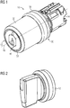
- FIG. 1 shows a first embodiment of an electromechanical switching device 10 according to the invention, which serves to provide an electrical switching state in response to a manual operation.
- the electromechanical switching device 10 is also for arranging in a non-illustrated control panel of a not shown formed electrical control device.
- the electromechanical switching device 10 has a rotatably mounted and manually operable actuating unit 46 in the form of a key-operated lock 46.
- the electromechanical switching device 10 has a switching unit 14 that can be connected to the lock 46, which in the present case provides two electrical connections 62 of the electromechanical switching device 10 and electrically interconnects them depending on the electrical switching state and the switching element displaceably mounted in a longitudinal direction 16 of the electromechanical switching device 10 18 ( FIG. 4 ) having.
- the switching unit 14 is designed to assume the switching state as a function of the operation of the lock 46.
- the electromechanical switching device 10 according to FIG. 1 a coupling unit 20, which mechanically connects the lock 46 and the switching unit 14 with each other.
- the coupling unit 20 is further configured to transmit the manual operation of the lock 46 to the switching element 18 of the switching unit 14.
- FIG. 2 shows in a perspective schematic view of a second embodiment of an actuating unit according to the invention, namely a rotary knob 12. This can instead of the lock 46 according to FIG. 1 to be assembled.
- FIG. 3 shows in a perspective-schematic exploded view of the electromechanical switching device 10 according to FIG. 1 with optional embodiments for the coupling unit 20.
- the lock 46 in a sleeve 50th arranged rotationally fixed.
- the lock 46 includes a rotatably mounted unspecified lock cylinder which can be rotatably actuated upon insertion of a mating key, that is, a key with a corresponding key secret.
- the front side of the lock cylinder is surrounded by a display plate 52 which is axially supported in the longitudinal direction 16 of the electromechanical switching device 10 between the sleeve 50 and the lock 46.
- a stop plate 22 is arranged, by means of which a rotation angle for the manual operation of the lock 46 can be limited or adjusted.
- the stop disc 22 forms a rotation angle limiting unit.
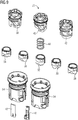
- Stop disk side is followed by the coupling unit 20, which in the present case comprises a selection of three possible gate elements 38, 40, 42, a spring 48 and a selection of crown elements 28, 30, 32, 34, 36.
- the coupling unit 20 is received on the lock side together with the stop disc 22 in a rosette 54, which also provides terminal contacts of the terminals 62 end, which serve to connect electrical lines, between which a desired switching function is to be realized.
- a slider 18 is also mounted axially displaceable in the rosette 54 in the direction 16.
- the rosette 54 may be connected to the sleeve 50 by means of a front ring 56. For this purpose, corresponding threads (not shown) are provided, so that these components can be screwed together.
- FIG. 4 shows a corresponding representation of an electromechanical switching device 10 with a rotary knob 12 according to FIG. 2 ,
- the structure otherwise corresponds basically as he already did FIG. 3 has been explained, which is why reference is additionally made to the relevant remarks.
- the electromechanical switching device 10 according to the invention is modular and components can be assembled as needed to form the respective desired electromechanical switching device can. The operation can for example be done either by a handle in the form of the rotary knob or by a key operation of a castle. Each of these elements is connected to the corresponding link element either non-positively or positively.
- the link element serves to convert the rotational movement into a translational movement with respect to the slide. Accordingly, the rotational movement is transmitted to the slide 18 by means of a link of the link element.
- the crown element is mounted longitudinally displaceable in direction 16 in the link element. At the same time it is rotatably connected to the link element, so that the crown element follows a rotational movement of the link element.
- the crown element has a crown on which a shelf 58 faces.
- the shelf 58 is rotationally fixed and arranged in the longitudinal direction 16 fixed in the rosette 54. Due to a bias by the spring 48, the Kronenkulisse is located on an unspecified projection of the shelf 58 at.
- contours of the crown elements functions such as latching or groping both in conjunction with a lock and in conjunction with a rotary knob realized.
- contours of the crown elements functions such as latching or groping both in conjunction with a lock and in conjunction with a rotary knob realized.
- five variants are possible, wherein the crown elements for both types of electromechanical switching devices can be identical.
- the gate element provides the function of enabling a two-actuator or a three-actuator as a rotary actuator.
- each of three variants exist. The differences lie in the receptacle of the actuating unit 12, 44, 46.
- the actuating unit 12, 44, 46 is latched to the link element 38, 40, 42.
- the lock 46 is positively connected to the link element 38, 40, 42.
- a starting position of the actuating unit 12, 44, 46 are determined.
- three variants are provided, namely left, center and right ( FIG. 8 ).
- the corresponding starting positions are in FIG. 8 shown side by side.
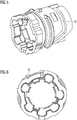
- FIGS. 5 and 6 is a schematic representation of an arrangement of one of the link elements, here the link element 42, without the stop plate 22 is shown.
- FIG. 9 shows in a perspective exploded view schematically different elements that can be summarized to the coupling unit 20. It can be seen that one of three link elements 38, 40, 42 can each be combined with one of the crown elements 28, 30, 32, 34, 36. In addition, the spring 48 is provided. These elements can be arranged in a respective rosette 54.
- Each of the gate elements 38, 40, 42 has an unspecified recess, in which a likewise not designated latching lug of a respective operating unit 12, 44, 46 can engage. Thereby, the respective gate element 38, 40, 42 rotatably connected to the respective rotatable element of the actuating unit 12, 44, 46 are connected. Depending on the positioning of the actuating unit 12, 44, 46 with respect to the link element 38, 40, 42, the respective starting position can be determined.
- FIGS. 10 and 11 show rotary knob 12, 44 as actuating units, wherein the backdrop side latching hooks 60 are provided which are with the above-mentioned recesses of the respective gate elements 38, 40, 42 in engagement when a respective gate element is connected to the respective rotary knob.
- FIG. 12 shows a schematic sectional view through the electromechanical switching device 10 according to FIG. 2 in the assembled state.
- FIG. 13 shows three possible starting positions of the rotary knob 12, as with the structure according to FIG. 12 are reachable.
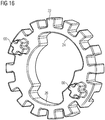
- FIGS. 14 and 15 show in a perspective schematic view of a connection of the lock 46 with the stop plate 22, wherein different rotational angle limits are provided.
- lock body side here single, projection 64 is provided which projects radially and into a recess 24 (FIG. FIG. 14 ) or 26 ( FIG. 15 ), depending on which angle of rotation is desired.
- the recesses 24, 26 provide openings and limit the angle of rotation about which the key in the lock 46 can be turned.
- the stop disc 22 is provided with two opposite partially circumferential openings, on the one hand the opening 24 and on the other hand the opening 26. By appropriate positioning of the stop plate 22 relative to the lock 46, the desired angle of rotation can be adjusted.
- the projection 64 then engages in the corresponding opening 24, 26 a. In FIG. 14 the angle of rotation is 90 °, whereas in FIG. 15 the angle of rotation is 45 °.
- FIG. 16 shows the stop plate 22 in a perspective individual view, from which the openings 24, 26 can be seen.
- the stop disc 22 can be rotatably connected to a lock body of the lock 46. In this way, the stop is reached.
- FIG. 17 shows in an overall perspective view of an electromechanical switching device 10, the rotary knob is based.
- the desired rotary knob for example, in the present embodiment, the rotary knob 12 or the rotary knob 44, are connected to the electromechanical switching device 10.
- the structure corresponds to how he already has FIG. 4 has been explained, which is why reference is additionally made to these statements.
- device features can of course also be formulated as process features and vice versa.
Description
Die vorliegende Erfindung betrifft eine elektromechanische Schalteinrichtung zum Bereitstellen einer elektrischen Verbindung zwischen wenigstens zwei Anschlüssen in Abhängigkeit von einem Schaltzustand aufgrund einer manuellen Betätigung, wobei die elektromechanische Schalteinrichtung zum Anordnen in einer Schalttafel einer elektrischen Steuereinrichtung ausgebildet ist und eine drehbar gelagerte und manuell betätigbare Betätigungseinheit sowie eine mit der Betätigungseinheit verbindbare Schalteinheit aufweist, wobei die Schalteinheit die wenigstens zwei elektrischen Anschlüsse der elektromechanischen Schalteinrichtung bereitstellt und in Abhängigkeit vom elektrischen Schaltzustand miteinander elektrisch verbindet, zu welchem Zweck die Schalteinheit wenigstens ein in eine Längsrichtung der elektromechanischen Schalteinrichtung verschiebbar gelagertes Schaltelement aufweist.The present invention relates to an electromechanical switching device for providing an electrical connection between at least two terminals in response to a switching state due to a manual operation, wherein the electromechanical switching device is designed for placement in a control panel of an electrical control device and a rotatably mounted and manually operable actuator unit and a The switching unit has at least two electrical connections of the electromechanical switching device and electrically interconnects depending on the electrical switching state, for which purpose the switching unit has at least one shifting element displaceably mounted in a longitudinal direction of the electromechanical switching device.
Gattungsgemäße elektromechanische Schalteinrichtungen sind dem Grunde nach bekannt, sodass es eines gesonderten druckschriftlichen Nachweises hierfür nicht bedarf. Üblicherweise werden sie in Schalttafeln eingesetzt, die der Steuerung von elektrischen Anlagen, zumindest teilweise elektrisch betriebenen Maschinen, Kombinationen hiervon oder dergleichen dienen. Die elektromechanischen Schalteinrichtungen dienen dabei insbesondere der Aktivierung beziehungsweise Deaktivierung von elektrisch steuerbaren Funktionen, die üblicherweise mittels einer Steuerspannung in Form einer Niederspannung aktiviert beziehungsweise deaktiviert werden. Dabei hat es sich durchgesetzt, für die elektromechanischen Schaltelemente überwiegend drehbetätigte elektromechanische Schalteinrichtungen einzusetzen. Dadurch kann einerseits eine einfache Handhabung erreicht werden und andererseits lässt sich auf diese Weise eine einfache Montage und Anordnung in der Schalttafel realisieren. Die Schalttafel kann durch eine Wand gebildet sein, die aus einem metallischen Werkstoff, beispielsweise Stahlblech oder dergleichen, gebildet sein kann. Sie kann aber auch aus einem Kunststoff, einem Verbundwerkstoff und/oder dergleichen gebildet sein. Daneben kann die Schalttafel aber auch als Schaltkasten beziehungsweise als Schaltschrank ausgebildet sein und einen abgeschlossenen Hohlraum bereitstellen, in dem vorzugsweise elektrische Leistungen angeschlossen sind.Generic electromechanical switching devices are basically known, so it does not require a separate printed evidence for this. Usually they are used in control panels, which serve the control of electrical installations, at least partially electrically operated machines, combinations thereof or the like. The electromechanical switching devices serve in particular the activation or deactivation of electrically controllable functions, which are usually activated or deactivated by means of a control voltage in the form of a low voltage. It has become established to use predominantly rotationally actuated electromechanical switching devices for the electromechanical switching elements. As a result, on the one hand a simple handling can be achieved and on the other hand can be realized in this way a simple installation and arrangement in the control panel. The control panel can through a wall be formed, which may be formed of a metallic material, such as steel sheet or the like. But it can also be formed of a plastic, a composite material and / or the like. In addition, the control panel can also be designed as a control box or as a control cabinet and provide a closed cavity in which preferably electrical power is connected.
Die Schalttafel weist üblicherweise eine an äußere Abmessungen der elektromechanischen Schalteinrichtung angepasste Öffnung auf, in die die elektromechanische Schalteinrichtung eingesetzt und befestigt ist.The switchboard usually has an opening adapted to external dimensions of the electromechanical switching device, into which the electromechanical switching device is inserted and fastened.
Bedienungsseitig ragt über eine Oberfläche der Schalttafel die drehbar gelagerte und manuell betätigbare Betätigungseinheit hinaus, sodass sie durch einen Bediener manuell betätigt werden kann. Rückseitig ragt dagegen die Schalteinheit hervor, die über Anschlüsse der Schalteinheit an elektrische Leitungen angeschlossen ist, um entsprechend des jeweiligen aktuellen Schaltzustands der elektromechanischen Schalteinheit eine elektrische Verbindung zwischen zwei oder mehreren der elektrischen Leitungen herzustellen beziehungsweise zu unterbrechen.Operator side protrudes beyond a surface of the panel, the rotatably mounted and manually operable actuator unit so that it can be manually operated by an operator. On the other hand, the rear side projects beyond the switching unit, which is connected to electrical lines via connections of the switching unit, in order to establish or interrupt an electrical connection between two or more of the electrical lines in accordance with the respective current switching state of the electromechanical switching unit.
Betätigungsseitig sind im Wesentlichen zwei verschiedene Ausführungsformen zu unterscheiden, und zwar eine schlüsselbetätigte Betätigungseinheit sowie zweitens eine Drehknebelbetätigungseinheit. Darüber hinaus gibt es eine Vielzahl von unterschiedlichen Ausgestaltungen in Bezug auf die Schalteinheit sowie der einnehmbaren Schaltzustände.On the actuation side, two different embodiments are essentially to be distinguished, namely a key-operated actuating unit and, secondly, a rotary knob actuating unit. In addition, there are a variety of different configurations with respect to the switching unit and the einnehmbaren switching states.
Für diese unterschiedlichen elektromechanischen Schaltelemente gibt es jeweils eigene Konstruktionen, die zu einer Vielzahl von unterschiedlichen elektromechanischen Schalteinrichtungen führen und die einen entsprechenden herstellungsseitigen Aufwand erfordern.For these different electromechanical switching elements, there are each own constructions that lead to a variety of different electromechanical switching devices and require a corresponding production-side effort.
Aus der
Die Erfindung hat es sich zur Aufgabe gemacht, den Aufwand für eine elektromechanische Schalteinheit zu reduzieren.The invention has set itself the task of reducing the cost of an electromechanical switching unit.
Mit der Erfindung wird eine elektromechanische Schalteinheit gemäß dem unabhängigen Anspruch 1 vorgeschlagen. Weitere vorteilhafte Weiterbildungen ergeben sich anhand von Merkmalen der abhängigen Ansprüche.With the invention, an electromechanical switching unit according to the independent claim 1 is proposed. Further advantageous developments will become apparent from the features of the dependent claims.
Mit der Erfindung wird insbesondere vorgeschlagen, dass die elektromechanische Schalteinrichtung eine Kupplungseinheit aufweist, die die Betätigungseinheit und die Schalteinheit mechanisch miteinander verbindet, und die ausgebildet ist, die manuelle Betätigung der Betätigungseinheit auf das Schaltelement der Schalteinheit zu übertragen, wobei die elektromechanische Schalteinrichtung durch zumindest die Betätigungseinheit, die Kupplungseinheit sowie die Schalteinheit in modularer Weise ausgebildet ist.With the invention is particularly proposed that the electromechanical switching device comprises a coupling unit which mechanically connects the actuating unit and the switching unit, and which is adapted to transmit the manual operation of the actuating unit to the switching element of the switching unit, wherein the electromechanical switching device by at least the Actuator, the coupling unit and the switching unit is formed in a modular manner.
Mittels der Kupplungseinheit wird erreicht, dass die elektromechanische Schalteinrichtung in modularer Weise aus den Komponenten Betätigungseinheit, Kupplungseinheit und Schalteinheit nahezu beliebig kombiniert herstellbar ist. Mittels der Kupplungseinheit können spezifische, vorzugsweise standardisierte, Verbindungen zwischen der Kupplungseinheit und der Betätigungseinheit sowie der Kupplungseinheit und der Schalteinheit geschaffen werden, sodass auf einfache Weise aus einem Bausatz aus wenigen Komponenten eine elektromechanische Schalteinrichtung der beliebigen Art zusammengestellt werden kann. Dabei erweist es sich als besonders vorteilhaft, dass bereits die Einzelkomponenten, nämlich die Kupplungseinheit, die Betätigungseinheit und die Schalteinheit sowie die diesen zugeordneten Elemente als vorgeprüfte Baugruppen genutzt werden können. Dadurch kann die Herstellung elektromechanischer Schalteinrichtungen erheblich vereinfacht werden, sodass auch kurzfristig unterschiedlichste elektromechanische Schalteinrichtungen bedarfsgerecht herstellbar sind. Mit der Erfindung kann also eine erhebliche Flexibilisierung hinsichtlich der Fertigung elektromechanischer Schalteinrichtungen erreicht werden. Darüber hinaus ermöglicht es die Erfindung, die einzelnen Komponenten der elektromechanischen Schalteinrichtung, nämlich die Kupplungseinheit, die Betätigungseinheit und die Schalteinheit, zu unterschiedlichen Zeitpunkten an unterschiedlichen Orten separat herzustellen und erst dann zur elektromechanischen Schalteinrichtung zusammenzuführen, wenn entsprechende Aufträge vorliegen. Die Module können durch die Betätigungseinheit, die Kupplungseinheit sowie die Schalteinheit gebildet sein.By means of the coupling unit is achieved that the electromechanical switching device in a modular manner from the components actuator unit, clutch unit and switching unit is almost arbitrarily combined produced. By means of the coupling unit specific, preferably standardized, connections between the coupling unit and the operating unit and the coupling unit and the switching unit can be created so that an electromechanical switching device of any kind can be assembled in a simple manner from a kit of a few components. It proves to be particularly advantageous that even the individual components, namely the coupling unit, the operating unit and the switching unit and the elements associated therewith can be used as pre-tested assemblies. As a result, the production of electromechanical switching devices can be considerably simplified, so that a variety of electromechanical switching devices can be produced as needed in the short term. With the invention, therefore, a considerable flexibility in terms of the production of electromechanical switching devices can be achieved become. In addition, the invention makes it possible to manufacture the individual components of the electromechanical switching device, namely the coupling unit, the actuating unit and the switching unit at different times separately at different locations and only then merge the electromechanical switching device when corresponding orders are present. The modules can be formed by the actuating unit, the coupling unit and the switching unit.
Gerade für die regelmäßig vorgesehene Anwendung im Niederspannungsbereich gemäß der Normung, insbesondere der Richtlinie 2006/95/EG des europäischen Parlaments und des Rates vom 12. Dezember 2006 zur Angleichung der Rechtsvorschriften der Mitgliedstaaten betreffend elektrische Betriebsmittel zur Verwendung innerhalb bestimmter Spannungsgrenzen erweist sich die Erfindung als besonders vorteilhaft. Bekanntermaßen werden an solche elektromechanische Schalteinrichtungen besondere technische Anforderungen gestellt, die auch besonderen Prüfungen genügen müssen. Trotz dieses besonderen Aufwands hinsichtlich der elektrischen Sicherheit kann mit der Erfindung der modulare Aufbau realisiert werden, der eine günstige Fertigung der elektromechanischen Schalteinrichtungen erlaubt.Especially for the regularly scheduled application in the low voltage area according to standardization, in particular the Directive 2006/95 / EC of the European Parliament and the Council of 12 December 2006 for the approximation of the laws of the member states concerning electrical equipment for use within certain voltage limits, the invention proves to be especially advantageous. As is known, special technical requirements are made of such electromechanical switching devices, which must also satisfy special tests. Despite this special effort in terms of electrical safety can be realized with the invention of the modular design, which allows a favorable production of the electromechanical switching devices.
Die elektromechanische Schalteinrichtung ist typischerweise als drehbetätigte elektromechanische Schalteinrichtung mit einer Längsachse versehen, die in der Regel zugleich auch eine Rotationsachse bezüglich der drehbaren Lagerung eines Betätigungselements der Betätigungseinheit darstellt. Bei Sonderbauformen können die Achsen auch voneinander abweichen. Üblicherweise ist die elektromechanische Schalteinrichtung aus Sicht der elektrischen Sicherheit in zwei Bereiche gegliedert, nämlich einen Bereich für die manuelle Betätigung, der hinreichend elektrisch isoliert gegenüber einem elektrisch aktiven Bereich ist, der die eigentliche Schaltfunktion entsprechend des Schaltzustands der elektromechanischen Schalteinrichtung bereitstellt. Die Schalteinheit stellt darüber hinaus in der Regel auch die Anschlüsse bereit, zwischen denen die elektrische Verbindung entsprechend des jeweiligen Schaltzustands hergestellt oder unterbrochen wird. Aufgrund dieser Konstruktion ragt der Betätigungsbereich üblicherweise aus der Schalttafel heraus, wohingegen der aktive Bereich vom Betätigungsbereich durch die Schalttafel insbesondere in Bezug auf die elektrische Sicherheit und die elektrische Isolation getrennt, insbesondere abgeschirmt, ist.The electromechanical switching device is typically provided as a rotationally actuated electromechanical switching device with a longitudinal axis, which usually also represents an axis of rotation with respect to the rotatable mounting of an actuating element of the actuating unit at the same time. With special designs, the axes can also differ from each other. Usually, the electromechanical switching device is divided into two areas from the point of view of electrical safety, namely an area for manual operation which is sufficiently electrically insulated from an electrically active area which provides the actual switching function in accordance with the switching state of the electromechanical switching device. The switching unit puts over it In addition, usually also the connections ready, between which the electrical connection is made or interrupted according to the respective switching state. Due to this construction, the operating area usually protrudes from the control panel, whereas the active area is separated from the operating area by the control panel, in particular with respect to electrical safety and electrical insulation, in particular shielded.
Die Kupplungseinheit stellt vorzugsweise einen Verbindungsbereich dar, der mit der Betätigungseinheit zur Übertragung einer Drehbewegung der Betätigungseinheit entsprechend drehtechnisch gekoppelt ist. Beispielsweise kann die Verbindung dadurch hergestellt sein, dass die Kupplungseinheit eine codierte Aufnahme für einen entsprechend entgegengesetzt codierten Vorsprung des Betätigungselements aufweist, sodass zwischen beiden eine drehfeste Verbindung erreicht werden kann. Es kann aber auch vorgesehen sein, dass ein Rastelement der Betätigungseinheit in eine Rastaufnahme der Kupplungseinheit eingreift, um die drehtechnische Verbindung herzustellen.The coupling unit preferably represents a connection region, which is correspondingly coupled in rotation with the actuating unit for transmitting a rotational movement of the actuating unit. For example, the connection can be made in that the coupling unit has a coded receptacle for a correspondingly opposite coded projection of the actuating element, so that between both a rotationally fixed connection can be achieved. However, it can also be provided that a latching element of the actuating unit engages in a latching receptacle of the coupling unit in order to produce the rotary connection.
Die Kupplungseinheit ist ferner dafür vorgesehen, die Drehbewegung, die mittels des Betätigungselements in die Kupplungseinheit eingeleitet wird, in eine translatorische Bewegung umzuwandeln und entsprechend das Schaltelement der Schalteinheit translatorisch zu verschieben. Dadurch kann das Schaltelement den gewünschten Schaltzustand realisieren. Entsprechend den jeweiligen Drehstellungen des Betätigungselements ergeben sich so entsprechende axiale Positionen des Schaltelements. Entsprechend der jeweiligen Positionen des Schaltelements in Bezug auf die jeweiligen Schaltzustände sind entsprechend Kontakte, die mit den Anschlüssen der Schalteinheit verbunden sind, geschaltet. Dadurch kann in gewünschter Weise mittels der elektromechanischen Schalteinrichtung gemäß der Erfindung eine Vielzahl von Schaltfunktionen mit nur wenigen Bauteilen realisiert werden.The coupling unit is further provided for converting the rotational movement, which is introduced by means of the actuating element into the coupling unit, into a translational movement and correspondingly displacing the switching element of the switching unit in a translatory manner. This allows the switching element to realize the desired switching state. Corresponding to the respective rotational positions of the actuating element, corresponding axial positions of the switching element thus result. Corresponding to the respective positions of the switching element with respect to the respective switching states, contacts connected to the terminals of the switching unit are respectively connected. As a result, a plurality of switching functions can be realized with only a few components in the desired manner by means of the electromechanical switching device according to the invention.
Das Schaltelement selbst kann beispielsweise axial gleitend geführt sein und einen oder mehrere elektrisch leitfähige Bereich aufweisen, mittels denen zwischen Kontakten der Schalteinheit elektrische Verbindungen hergestellt oder unterbrochen werden können.The switching element itself may, for example, be guided in an axially sliding manner and have one or more electrically conductive regions by means of which electrical connections can be made or interrupted between contacts of the switching unit.
Gemäß einer vorteilhaften Weiterbildung wird vorgeschlagen, dass die Kupplungseinheit eine Drehwinkelbegrenzungsscheibe aufweist, die wenigstens ein Drehwinkelbegrenzungselement aufweist. Vorzugsweise ist die Drehwinkelbegrenzungsscheibe im Verbindungsbereich zwischen der Kupplungseinheit und der Betätigungseinheit angeordnet. Mit der Drehwinkelbegrenzungsscheibe kann ein Drehwinkel des Betätigungselements in einer vorgebbaren Weise eingestellt werden. Beispielsweise kann der Drehwinkel auf 90 Grad begrenzt werden. Darüber hinaus kann der Drehwinkel auch auf 45 Grad begrenzt werden. Vorteilhaft ist die Drehwinkelbegrenzungsscheibe ausgebildet, mehrere Drehwinkel begrenzen zu können. Durch entsprechende Einstellung beziehungsweise Montage der Drehwinkelbegrenzungsscheibe kann erreicht werden, dass ein jeweiliger Begrenzungswinkel bezüglich einer manuellen Betätigung der Betätigungseinheit eingestellt werden kann. Die Drehwinkelbegrenzungselemente können beispielsweise durch Ausnehmungen, insbesondere Öffnungen, in der Drehwinkelbegrenzungsscheibe ausgebildet sein. Die Ausnehmung erstreckt sich vorzugsweise über einen Drehwinkelbereich, der einen Stellbereich über den gewünschten Drehwinkel ermöglicht.According to an advantageous development, it is proposed that the coupling unit has a rotational angle limiting disc which has at least one rotational angle limiting element. Preferably, the rotational angle limiting disc is arranged in the connecting region between the coupling unit and the actuating unit. With the rotation angle limiting disk, a rotation angle of the actuating element can be set in a predeterminable manner. For example, the rotation angle can be limited to 90 degrees. In addition, the rotation angle can be limited to 45 degrees. Advantageously, the rotation angle limiting disk is designed to be able to limit a plurality of rotation angles. By appropriate adjustment or assembly of the rotational angle limiting disc can be achieved that a respective limiting angle with respect to a manual actuation of the actuating unit can be adjusted. The rotation angle limiting elements can be formed, for example, by recesses, in particular openings, in the rotation angle limiting disk. The recess preferably extends over a rotation angle range, which allows a setting range over the desired rotation angle.
Gemäß einer Weiterbildung wird vorgeschlagen, dass die Drehwinkelbegrenzungsscheibe drehfest gegenüber der Schalteinheit angeordnet ist. Besonders vorteilhaft ist die Drehwinkelbegrenzungsscheibe mit der Schalteinheit über die Kupplungseinheit verbunden. Dadurch ist es möglich, den zulässigen Drehwinkel gegenüber der Schalteinheit als Bezugspunkt festzulegen.According to a further development, it is proposed that the rotation angle limiting disc is arranged rotationally fixed relative to the switching unit. Particularly advantageously, the rotation angle limiting disc is connected to the switching unit via the coupling unit. This makes it possible to set the permissible angle of rotation with respect to the switching unit as a reference point.
Eine Ausgestaltung gemäß der Erfindung schlägt vor, dass die Kupplungseinheit ein mit einem Kronenelement zusammen wirkendes Kulissenelement aufweist. Durch diese Ausgestaltung ist es auf einfache Weise möglich, die Drehbetätigung der Betätigungseinheit in eine axiale Bewegung umzuwandeln, die auf das Schaltelement einwirkt. Zugleich kann vorgesehen sein, dass das Kronenelement mit dem Kulissenelement drehfest verbunden ist, wobei das Kronenelement axial beweglich angeordnet ist und mit einem in einer Rosette drehfest und in Längsrichtung der elektromechanischen Schalteinrichtung festgelegt anordneten Einlegeboden zusammenwirkt, um die gewünschte Rast- und/oder Tastfunktionen bereitzustellen. Das Kulissenelement stellt vorzugsweise eine Kulisse bereit, die auf das Schaltelement einwirkt und eine Drehbewegung in eine axiale Bewegung des Schaltelements umwandelt. Vorzugsweise ist deshalb das Kulissenelement drehbar gelagert und drehfest mit einer Drehachse der Betätigungseinheit verbunden. Dadurch kann die Drehbewegung der Betätigungseinheit unmittelbar auf das Kulissenelement einwirken. Auf diese Weise lässt sich eine einfache, leicht bedienbare Anordnung erreichen.An embodiment according to the invention proposes that the coupling unit has a crank element acting together with a crown element. By this configuration, it is easily possible to convert the rotary actuator of the actuator into an axial movement, which acts on the switching element. At the same time it can be provided that the crown element is rotatably connected to the link element, wherein the crown element is arranged axially movable and cooperates with a rotatably fixed in a rosette and fixed in the longitudinal direction of the electromechanical switching device arranged shelf to provide the desired locking and / or tactile functions , The link element preferably provides a link which acts on the switching element and converts a rotational movement into an axial movement of the switching element. Preferably, therefore, the link element is rotatably mounted and rotatably connected to a rotational axis of the actuating unit. As a result, the rotational movement of the actuating unit can act directly on the link element. In this way, a simple, easy-to-use arrangement can be achieved.
Darüber hinaus wird vorgeschlagen, dass das Kronenelement mit dem Kulissenelement drehbar und in die Längsrichtung der elektromechanischen Schalteinrichtung im Kulissenelement verschiebbar gelagert ist. Dadurch ist es möglich, in Zusammenwirkung mit dem Kulissenelement eine Drehbetätigung der Betätigungseinheit in eine Längsbewegung zu wandeln und auf die Schalteinrichtung einwirken zu lassen. Vorzugsweise weist das Schaltelement hierfür wenigstens einen Kontaktbereich auf, der mit der durch das Kulissenelement bereitgestellten Kulisse zusammenwirkt. Die verschiebbare Lagerung des Kronenelements im Kulissenelement ermöglicht es, dass eine dem Einlegeboden zugewandte Kronenkulisse mit dem Einlegeboden zusammenwirkt und dadurch gewünschte mechanische Funktionen wie Rasten, Tasten und/oder dergleichen bereitstellt. Beispielsweise könnenn zu diesem Zweck eine oder mehrere Lagerstellen für das Kronenelement im Kulissenelement vorgesehen sein.In addition, it is proposed that the crown element is rotatably mounted with the link element and slidably mounted in the longitudinal direction of the electromechanical switching device in the link element. This makes it possible, in cooperation with the link element to convert a rotary actuator of the actuating unit in a longitudinal movement and to act on the switching device. For this purpose, the switching element preferably has at least one contact region which cooperates with the backdrop provided by the link element. The displaceable mounting of the crown element in the gate element makes it possible for a crown gate facing the shelf to interact with the shelf and thereby provide desired mechanical functions such as detents, buttons and / or the like. For example, one or more bearing points for the crown element can be provided in the link element for this purpose.
Besonders vorteilhaft erweist es sich, wenn das Kronenelement in Richtung des Einlegebodens vorgespannt ist. Dadurch kann einerseits gewährleistet werden, dass das Kronenelement permanent in Eingriff mit dem Einlegeboden ist, und zwar unabhängig von einer Drehstellung des Betätigungselements.It proves particularly advantageous if the crown element is biased in the direction of the shelf. On the one hand, this ensures that the crown element is permanently in engagement with the shelf, regardless of a rotational position of the actuating element.
Weiterhin wird vorgeschlagen, dass die Kupplungseinheit einen modularen Aufbau aufweist, insbesondere als separates Modul jeweils mit einem Kronenelement, einem Kulissenelement und einer Feder. Mit dem modularen Aufbau ist es möglich, die elektromechanische Schalteinrichtung bedarfsgerecht in einer Vielzahl von Funktionsausgestaltungen auf einfache Weise und flexibel erstellen zu können. Die Module können durch Elemente der Kupplungseinheit gebildet sein. Dadurch kann der grundsätzliche mechanische Aufbau der elektromechanischen Schalteinrichtung im Wesentlichen unabhängig von den verwendeten Modulen beibehalten werden.Furthermore, it is proposed that the coupling unit has a modular construction, in particular as a separate module in each case with a crown element, a link element and a spring. With the modular structure, it is possible to create the electromechanical switching device as needed in a variety of functional configurations in a simple and flexible manner. The modules may be formed by elements of the coupling unit. Thereby, the basic mechanical structure of the electromechanical switching device can be maintained substantially independent of the modules used.
Gemäß einer weiteren Ausgestaltung wird vorgeschlagen, dass das Kronenelement und/oder das Kulissenelement in der Kupplungseinheit austauschbar angeordnet sind. Diese Ausgestaltung erlaubt es, auch nachträglich eine elektromechanische Schalteinrichtung mit einer anderen Funktion auszurüsten. Dazu können dann auf einfache Weise das Kronenelement und/oder das Kulissenelement ausgetauscht werden. Vorzugsweise sind standardisierte Abmessungen für das Kronenelement und/oder das Kulissenelement vorgesehen, sodass sie in der Kupplungseinheit auf einfache Weise nach Belieben getauscht werden können.According to a further embodiment, it is proposed that the crown element and / or the link element are arranged interchangeably in the coupling unit. This embodiment makes it possible to retrofit an electromechanical switching device with another function. For this purpose, the crown element and / or the link element can then be easily replaced. Preferably, standardized dimensions for the crown element and / or the gate element are provided so that they can be easily exchanged in the coupling unit at will.
Weitere Vorteile und Merkmale sind der folgenden Beschreibung von Ausführungsbeispielen zu entnehmen. In den Figuren werden gleiche Bauteile und Funktionen mit gleichen Bezugszeichen bezeichnet.Further advantages and features can be found in the following description of exemplary embodiments. In the figures, the same components and functions are denoted by the same reference numerals.
Es zeigen:
- FIG 1
- eine modulare elektromechanische Schalteinrichtung gemäß der Erfindung in einer schematischperspektivischen Ansicht,
- FIG 2
- in einer schematisch-perspektivischen Darstellung einen Drehknebel als Betätigungseinheit für die elektromechanische Schalteinrichtung gemäß der Erfindung,
- FIG 3
- in schematischer Explosionsdarstellung die elektromechanische Schalteinrichtung gemäß
FIG 1 , wobei optional einsetzbare Bauelemente dargestellt sind, - FIG 4
- eine weitere elektromechanische Schalteinrichtung der Erfindung in einer perspektivischen Explosionsdarstellung mit einer Betätigungseinheit gemäß
Fig. 2 , - FIG 5
- eine schematisch-perspektivische Ansicht einer Anschlagscheibe in Verbindung mit einem Kulissenelement,
- FIG 6
- eine schematische Draufsicht auf die Anordnung gemäß
FIG 5 , - FIG 7
- eine schematisch-perspektivische Ansicht eines Schlosses in Verbindung mit der in den
FIG 5 und 6 dargestellten Baugruppe, - FIG 8
- eine shematische Ansicht von drei möglichen Ausgangsstellungen, die mit der Baugruppe gemäß
FIG 7 realisierbar sind, - FIG 9
- in einer schematischen ausgeschnittenen Explosionsdarstellung Möglichkeiten für die Kupplungseinheit in Verbindung mit der Schalteinheit,
- FIG 10
- eine schematische Seitenansicht eines ersten Drehknebels als Betätigungseinheit gemäß der Erfindung,
- FIG 11
- in einer schematischen Seitenansicht einen zweiten Drehknebel als Betätigungseinheit gemäß der Erfindung;
- FIG 12
- eine schematische Schnittansicht eines Ausschnitts der elektromechanischen Schalteinrichtung gemäß
FIG 4 in einem zusammengefügten Zustand, - FIG 13
- in schematischer Darstellung mögliche Ausgangsstellungen für den Drehknebel gemäß
FIG 12 , - FIG 14
- eine schematische Darstellung einer ersten Ausgestaltung einer Anschlagscheibe mit dem Betätigungselement,
- FIG 15
- eine schematische Darstellung einer zweiten Ausgestaltung der Anschlagscheibe in Verbindung mit dem Betätigungselement in einer schematischperspektivischen Ansicht wie in
FIG 14 , - FIG 16
- in einer schematisch-perspektivischen Darstellung die Anschlagscheibe gemäß den
FIG 14 und 15 und - FIG 17
- in einer schematisch-perspektivischen Ansicht eine weitere Ausgestaltung für eine elektromechanische Schalteinrichtung gemäß der Erfindung, wobei wahlweise unterschiedliche Betätigungseinheiten montierbar sind.
- FIG. 1
- a modular electromechanical switching device according to the invention in a schematic perspective view,
- FIG. 2
- in a schematic perspective view of a rotary knob as an actuating unit for the electromechanical switching device according to the invention,
- FIG. 3
- in a schematic exploded view of the electromechanical switching device according to
FIG. 1 , wherein optionally usable components are shown, - FIG. 4
- a further electromechanical switching device of the invention in an exploded perspective view with an actuating unit according to
Fig. 2 . - FIG. 5
- a schematic-perspective view of a stop plate in conjunction with a link element,
- FIG. 6
- a schematic plan view of the arrangement according to
FIG. 5 . - FIG. 7
- a schematic-perspective view of a castle in conjunction with the in the
FIGS. 5 and 6 represented assembly, - FIG. 8
- a schematic view of three possible starting positions, with the assembly according to
FIG. 7 are feasible, - FIG. 9
- in a schematic cut-away exploded view possibilities for the coupling unit in conjunction with the switching unit,
- FIG. 10
- a schematic side view of a first rotary knob as an actuating unit according to the invention,
- FIG. 11
- in a schematic side view of a second rotary knob as an actuating unit according to the invention;
- FIG. 12
- a schematic sectional view of a section of the electromechanical switching device according to
FIG. 4 in an assembled state, - FIG. 13
- in a schematic representation possible starting positions for the rotary knob according to
FIG. 12 . - FIG. 14
- a schematic representation of a first embodiment of a stop plate with the actuating element,
- FIG. 15
- a schematic representation of a second embodiment of the stop plate in conjunction with the actuating element in a schematic perspective view as in
FIG. 14 . - FIG. 16
- in a schematic perspective view of the stop plate according to the
FIGS. 14 and 15 and - FIG. 17
- in a schematic perspective view, a further embodiment of an electromechanical switching device according to the invention, wherein optionally different actuation units can be mounted.
Ferner umfasst die elektromechanische Schalteinrichtung 10 gemäß
Aus den
An einer der Anzeigescheibe 52 gegenüberliegenden Stirnseite des Schlosses 46 ist eine Anschlagscheibe 22 angeordnet, mittels der ein Drehwinkel für die manuelle Betätigung des Schlosses 46 begrenzt beziehungsweise eingestellt werden kann. Insofern bildet die Anschlagscheibe 22 eine Drehwinkelbegrenzungseinheit.On a
Anschlagscheibenseitig schließt sich die Kupplungseinheit 20 an, die vorliegend eine Auswahl von drei möglichen Kulissenelementen 38, 40, 42, eine Feder 48 sowie eine Auswahl von Kronenelementen 28, 30, 32, 34, 36 umfasst. Je nach gewünschter Schalt- und/oder Betätigungsfunktion können Kulissenelemente und Kronenelemente miteinander kombiniert werden. Die Kupplungseinheit 20 ist zusammen mit der Anschlagscheibe 22 schlossseitig in einer Rosette 54 aufgenommen, die zugleich auch Anschlusskontakte der Anschlüsse 62 endseitig bereitstellt, die zum Anschließen elektrischer Leitungen dienen, zwischen denen eine gewünschte Schaltfunktion realisiert werden soll. Um die gewünschte Schaltfunktion zwischen den Schaltkontakten der Anschlüsse 62 realisieren zu können, ist ferner ein Schieber 18 in der Rosette 54 axial verschieblich in Richtung 16 gelagert. Die Rosette 54 kann mit der Hülse 50 mittels eines Frontrings 56 verbunden werden. Zu diesem Zweck sind entsprechende Gewinde (nicht dargestellt) vorgesehen, sodass diese Bauteile miteinander verschraubt werden können.Stop disk side is followed by the
Das Kulissenelement dient dazu, die Drehbewegung in eine translatorische Bewegung in Bezug auf den Schieber umzuwandeln. Demzufolge wird mittels einer Kulisse des Kulissenelements die Drehbewegung auf den Schieber 18 übertragen. Ferner ist im Kulissenelement das Kronenelement längsverschieblich in Richtung 16 gelagert. Zugleich ist es drehfest mit dem Kulissenelement verbunden, sodass das Kronenelement einer Drehbewegung des Kulissenelements folgt. Das Kronenelement weist eine Kronenkulisse auf die einem Einlegeboden 58 zugewandt ist. Der Einlegeboden 58 ist drehfest und in Längsrichtung 16 fixiert in der Rosette 54 angeordnet. Aufgrund einer Vorspannung durch die Feder 48 liegt die Kronenkulisse an einem nicht bezeichneten Vorsprung des Einlegebodens 58 an. Durch die hierdurch bereitgestellte Leitkurve im Kronenelement und im Einlegeboden gleiten diese Elemente aufeinander, sodass eine Rast- und/oder eine Tastfunktion erreicht werden kann.The link element serves to convert the rotational movement into a translational movement with respect to the slide. Accordingly, the rotational movement is transmitted to the
So sind mit Hilfe von Konturen der Kronenelemente Funktionen wie rastend oder tastend sowohl in Verbindung mit einem Schloss als auch in Verbindung mit einem Drehknebel realisierbar. Beispielsweise sind fünf Varianten möglich, wobei die Kronenelemente für beide Typen von elektromechanischen Schalteinrichtungen identisch sein können.Thus, with the help of contours of the crown elements functions such as latching or groping both in conjunction with a lock and in conjunction with a rotary knob realized. For example, five variants are possible, wherein the crown elements for both types of electromechanical switching devices can be identical.
Folgende Varianten für Rasten und Tasten können in dieser Ausgestaltung realisiert sein:
- Symbole ( - ) ist gleich Rasten
- Symbole (> oder <) ist gleich Tasten nach Links oder Rechts
- Symbols (-) is the same as rest
- Icons (> or <) are equal to left or right buttons
Das Kulissenelement stellt die Funktion bereit, einen Zwei-Steller oder einen Drei-Steller als Drehbetätigungseinheit zu ermöglichen. In der vorliegenden Ausgestaltung sind jeweils drei Varianten vorhanden. Die Unterschiede liegen in der Aufnahme der Betätigungseinheit 12, 44, 46. Die Betätigungseinheit 12, 44, 46 wird mit dem Kulissenelement 38, 40, 42 verrastet. Zum Beispiel wird das Schloss 46 formschlüssig an das Kulissenelement 38, 40, 42 angebunden.The gate element provides the function of enabling a two-actuator or a three-actuator as a rotary actuator. In the present embodiment, each of three variants exist. The differences lie in the receptacle of the
Durch die Positionierung der Betätigungseinheit 12, 44, 46 in Bezug auf das jeweilige Kulissenelement 38, 40, 42 kann eine Ausgangsstellung der Betätigungseinheit 12, 44, 46 festgelegt werden. In der vorliegenden Ausgestaltung sind drei Varianten vorgesehen, und zwar links, Mitte und rechts (
In den
Die Ausnehmungen 24, 26 stellen Öffnungen bereit und begrenzen den Drehwinkel, um den der Schlüssel im Schloss 46 gedreht werden kann. Vorliegend ist die Anschlagscheibe 22 mit zwei gegenüberliegenden teilumlaufenden Öffnungen versehen, und zwar einerseits der Öffnung 24 und andererseits der Öffnung 26. Durch entsprechende Positionierung der Anschlagscheibe 22 gegenüber dem Schloss 46 kann der gewünschte Drehwinkel eingestellt werden. Der Vorsprung 64 greift dann in die entsprechende Öffnung 24, 26 ein. In
Die Beschreibung der vorliegenden Ausführungsbeispiele dient lediglich der Erläuterung der Erfindung und ist für diese nicht beschränkend. Selbstverständlich können Merkmale der Beschreibung und der Figuren in nahezu beliebiger Weise miteinander kombiniert werden, um zu weiteren vorteilhaften Ausgestaltungen im Rahmen der Erfindung gelangen zu können.The description of the present embodiments is merely illustrative of the invention and is not limitative of it. Of course, features of the description and the figures can be combined with one another in almost any desired manner in order to arrive at further advantageous embodiments within the scope of the invention.
Darüber hinaus können Vorrichtungsmerkmale natürlich auch als Verfahrensmerkmale formuliert sein und umgekehrt.In addition, device features can of course also be formulated as process features and vice versa.
- 1010
- elektromechanische Schalteinrichtungelectromechanical switching device
- 1212
- Drehknebelrotary knob
- 1414
- Schalteinheitswitching unit
- 1616
- Längsrichtunglongitudinal direction
- 1818
- Schaltelementswitching element
- 2020
- Kupplungseinheitclutch unit
- 2222
- Anschlagscheibestop disc
- 2424
- Öffnungopening
- 2626
- Öffnungopening
- 2828
- Kronenelementcrown element
- 3030
- Kronenelementcrown element
- 3232
- Kronenelementcrown element
- 3434
- Kronenelementcrown element
- 3636
- Kronenelementcrown element
- 3838
- Kulissenelementlink element
- 4040
- Kulissenelementlink element
- 4242
- Kulissenelementlink element
- 4444
- Drehknebelrotary knob
- 4646
- Schlosslock
- 4848
- Federfeather
- 5050
- Hülseshell
- 5252
- Anzeigescheibeindicator disc
- 5454
- Rosetterosette
- 5656
- Frontringfront ring
- 5858
- Einlegebodenshelf
- 6060
- Rasthakenlatch hook
- 6262
- Anschlusskontaktconnection contact
- 6464
- Vorsprunghead Start
- 6666
- Vorsprunghead Start
Claims (8)
- Electromechanical switching device (10) for making available an electrical connection between at least two terminals (62) as a function of a switched state on the basis of a manual activation, wherein the electromechanical switching device (10) is designed to be arranged in a switchboard of an electrical control device and has an activation unit (12, 44, 46) which is rotatably mounted and can be activated manually and a switching unit (14) which can be connected to the activation unit (12, 44, 46), wherein the switching unit (14) makes available the at least two electrical terminals (62) of the electromechanical switching device (10) and electrically connects them to one another as a function of the electrical switched state, for which purpose the switching unit (14) has at least one switching element (18) which is mounted so as to be slideable in a longitudinal direction (16) of the electromechanical switching device (10), wherein a coupling unit (20) which connects the activation unit (12, 44, 46) and the switching unit (14) to one another mechanically and which is designed to transmit the manual activation of the activation unit (12, 44, 46) to the switching element (18) of the switching unit (14), wherein the electromechanical switching device (10) is embodied in a modular fashion by means of at least the activation unit (12, 44, 46), the coupling unit (20) and the switching unit (14), wherein the coupling unit (20) has a link element (38, 40, 42) which interacts with a crown element (28, 30, 32, 34, 36), wherein the link element (38, 40, 42) converts the rotational movement of the activation unit (12, 44, 46) into a translatory movement with respect to the slider element (18), which is mounted so as to be slidable, by means of a link, characterized in that the crown element (28, 30, 32, 34, 36) is mounted so as to be rotatable with the link element (38, 40, 42) and so that it is slidable in the link element (38, 40, 42) in the longitudinal direction (16) of the electromechanical switching device (10), and in that,
owing to prestress by a spring (48), the crown element (28, 30, 32, 34, 36) slides on an insertion base (58) which is fixed in terms of rotation and secured in the longitudinal direction (16) in the switching unit (14), with the result that a latching function and/or an instantaneous-contact function can be brought about. - Electromechanical switching device according to Claim 1, characterized in that the coupling unit (20) has a rotational-angle-limiting disk (22) which has at least one rotational-angle-limiting element (24, 26).
- Electromechanical switching device according to Claim 2, characterized in that the rotational-angle-limiting disk (22) is arranged in a rotationally fixed fashion with respect to the switching unit (14).
- Electromechanical switching device according to Claim 1, characterized in that the link element (38, 40, 42) is rotatably mounted and connected in a rotationally fixed fashion to a rotational axis (44) of the activation unit (12, 44, 46).
- Electromechanical switching device according to either one of Claims 1 and 4, characterized in that the crown element (28, 30, 32, 34, 36) is prestressed in the direction of an insertion base (58).
- Electromechanical switching device according to one of Claims 1, 4 or 5, characterized in that a link of the link element (38, 40, 42) is mechanically connected to the switching element (18).
- Electromechanical switching device according to one of Claims 1 to 6, characterized in that the coupling unit (20) has a modular design, in particular as a separate module, in each case with a crown element (28, 30, 32, 34, 36), a link element (38, 40, 42) and a spring (48).
- Electromechanical switching device according to one of Claims 1 to 7, characterized in that the crown element (28, 30, 32, 34, 36) and/or the link element (38, 40, 42) are arranged in an exchangeable fashion in the coupling unit (20).
Priority Applications (3)
| Application Number | Priority Date | Filing Date | Title |
|---|---|---|---|
| EP14199290.9A EP3035357B1 (en) | 2014-12-19 | 2014-12-19 | Modular electromechanical switch element |
| US14/966,753 US9679716B2 (en) | 2014-12-19 | 2015-12-11 | Modular electromechanical switching element |
| CN201510954845.9A CN105719883B (en) | 2014-12-19 | 2015-12-17 | Modular electric mechanical switch element |
Applications Claiming Priority (1)
| Application Number | Priority Date | Filing Date | Title |
|---|---|---|---|
| EP14199290.9A EP3035357B1 (en) | 2014-12-19 | 2014-12-19 | Modular electromechanical switch element |
Publications (2)
| Publication Number | Publication Date |
|---|---|
| EP3035357A1 EP3035357A1 (en) | 2016-06-22 |
| EP3035357B1 true EP3035357B1 (en) | 2017-07-19 |
Family
ID=52231918
Family Applications (1)
| Application Number | Title | Priority Date | Filing Date |
|---|---|---|---|
| EP14199290.9A Active EP3035357B1 (en) | 2014-12-19 | 2014-12-19 | Modular electromechanical switch element |
Country Status (3)
| Country | Link |
|---|---|
| US (1) | US9679716B2 (en) |
| EP (1) | EP3035357B1 (en) |
| CN (1) | CN105719883B (en) |
Families Citing this family (2)
| Publication number | Priority date | Publication date | Assignee | Title |
|---|---|---|---|---|
| USD817899S1 (en) * | 2016-06-02 | 2018-05-15 | Shin Chin Industrial Co., Ltd. | Portion of a switch |
| US11116501B1 (en) * | 2020-04-10 | 2021-09-14 | Lexington Medical, Inc. | Surgical handle articulation assemblies |
Family Cites Families (10)
| Publication number | Priority date | Publication date | Assignee | Title |
|---|---|---|---|---|
| US4282414A (en) * | 1979-08-30 | 1981-08-04 | Westinghouse Electric Corp. | Convertible switch operator |
| CH666765A5 (en) * | 1985-02-08 | 1988-08-15 | Sprecher & Schuh Ag | OPERATING DEVICE FOR A SWITCH WITH A ROTATABLE HANDLE. |
| DE3521155A1 (en) * | 1985-06-13 | 1986-12-18 | Brown, Boveri & Cie Ag, 6800 Mannheim | Operating element for an explosion-proof switch |
| US6025564A (en) * | 1999-05-11 | 2000-02-15 | Eaton Corporation | Single stalk steering column switch |
| US6274835B1 (en) * | 1999-11-15 | 2001-08-14 | Siemens Energy & Automation | Selector switch operator |
| MXPA06011133A (en) | 2004-03-30 | 2007-01-25 | Schneider Electric Ind Sas | Rotary knob for electrical system. |
| FR2882463B1 (en) * | 2005-02-24 | 2007-03-30 | Schneider Electric Ind Sas | TURN BUTTON WITH LOCK |
| DE102007014231A1 (en) * | 2007-03-24 | 2008-09-25 | Hartmann-Exact Gmbh | Switching unit, particularly airbag deactivating switch, has switching chamber, which is limited by housing upper part, housing lower part and moving operating link |
| JP2013161695A (en) * | 2012-02-07 | 2013-08-19 | Alpha Corp | Ignition switch coupling structure |
| ITVI20120274A1 (en) * | 2012-10-17 | 2014-04-18 | Pizzato Elettrica Srl | ROTARY POTENTIOMETER |
-
2014
- 2014-12-19 EP EP14199290.9A patent/EP3035357B1/en active Active
-
2015
- 2015-12-11 US US14/966,753 patent/US9679716B2/en active Active
- 2015-12-17 CN CN201510954845.9A patent/CN105719883B/en active Active
Non-Patent Citations (1)
| Title |
|---|
| None * |
Also Published As
| Publication number | Publication date |
|---|---|
| CN105719883B (en) | 2018-08-31 |
| US20160181030A1 (en) | 2016-06-23 |
| US9679716B2 (en) | 2017-06-13 |
| CN105719883A (en) | 2016-06-29 |
| EP3035357A1 (en) | 2016-06-22 |
Similar Documents
| Publication | Publication Date | Title |
|---|---|---|
| EP2436858B1 (en) | Locking cylinder for a lock | |
| DE102012111408B3 (en) | Locking mechanism for plug connector, has primary spring element that is provided to exert force on primary locking element such that positive movement of primary locking element in specific position is produced | |
| DE112018004505T5 (en) | Connection locking actuator device for vehicle input connection | |
| EP1736622B1 (en) | Lock cylinder | |
| EP2584577B1 (en) | Multi-pole switch fuse assembly for busbar systems | |
| EP3035357B1 (en) | Modular electromechanical switch element | |
| EP1353257B1 (en) | Joystick comprising actuators | |
| WO2019076620A1 (en) | Electrical connector part having a locking element | |
| DE112018004506T5 (en) | Connection locking actuator device for vehicle input connection | |
| DE112018004978T5 (en) | Connection lock actuator device for vehicle input connection | |
| WO2009019175A1 (en) | Coupling arrangement for transmission of the rotational movement of a switching shaft of an electrical switch to at least one position signalling device | |
| EP1155428B1 (en) | Drive device for a switching device, especially for earthing switches of medium-voltage switchgear | |
| DE102015002863A1 (en) | Safety switch arrangement | |
| EP2467862B1 (en) | Locking mechanism for a electrical switching unit | |
| EP1869688B1 (en) | Multi-pole switching device with an additional housing and a mutual mechanical locking apparatus | |
| EP2674553B1 (en) | Locking cylinder | |
| EP3204581B1 (en) | Motor vehicle door lock | |
| WO1994017577A1 (en) | Device carrier for a low-voltage switching station | |
| DE102018122016B3 (en) | Coupling device for a door fitting, door fitting system and method for coupling or uncoupling a coupling device | |
| EP1769515B1 (en) | Operating module for a motor vehicle | |
| DE2462034C3 (en) | Key suitable for assembling keyboards | |
| DE2809348C3 (en) | Switching device | |
| DE2462035A1 (en) | Snap key keyboard structure - has keys snap connected into substructure which has openings in U-shaped formation to accommodate them | |
| DE102004002754B4 (en) | Vehicle lock with a child safety actuator | |
| DE10349872A1 (en) | Multi-pole conductor interface, especially for motor vehicle has coding device specifically configured to receive coding element connected to associated line contact so as to avoid loss |
Legal Events
| Date | Code | Title | Description |
|---|---|---|---|
| PUAI | Public reference made under article 153(3) epc to a published international application that has entered the european phase |
Free format text: ORIGINAL CODE: 0009012 |
|
| AK | Designated contracting states |
Kind code of ref document: A1 Designated state(s): AL AT BE BG CH CY CZ DE DK EE ES FI FR GB GR HR HU IE IS IT LI LT LU LV MC MK MT NL NO PL PT RO RS SE SI SK SM TR |
|
| AX | Request for extension of the european patent |
Extension state: BA ME |
|
| 17P | Request for examination filed |
Effective date: 20160720 |
|
| RBV | Designated contracting states (corrected) |
Designated state(s): AL AT BE BG CH CY CZ DE DK EE ES FI FR GB GR HR HU IE IS IT LI LT LU LV MC MK MT NL NO PL PT RO RS SE SI SK SM TR |
|
| 17Q | First examination report despatched |
Effective date: 20161122 |
|
| GRAP | Despatch of communication of intention to grant a patent |
Free format text: ORIGINAL CODE: EPIDOSNIGR1 |
|
| RIC1 | Information provided on ipc code assigned before grant |
Ipc: H01H 19/635 20060101AFI20170119BHEP Ipc: H01H 19/03 20060101ALN20170119BHEP |
|
| INTG | Intention to grant announced |
Effective date: 20170215 |
|
| GRAS | Grant fee paid |
Free format text: ORIGINAL CODE: EPIDOSNIGR3 |
|
| GRAA | (expected) grant |
Free format text: ORIGINAL CODE: 0009210 |
|
| AK | Designated contracting states |
Kind code of ref document: B1 Designated state(s): AL AT BE BG CH CY CZ DE DK EE ES FI FR GB GR HR HU IE IS IT LI LT LU LV MC MK MT NL NO PL PT RO RS SE SI SK SM TR |
|
| REG | Reference to a national code |
Ref country code: GB Ref legal event code: FG4D Free format text: NOT ENGLISH |
|
| REG | Reference to a national code |
Ref country code: CH Ref legal event code: EP |
|
| REG | Reference to a national code |
Ref country code: IE Ref legal event code: FG4D Free format text: LANGUAGE OF EP DOCUMENT: GERMAN |
|
| REG | Reference to a national code |
Ref country code: AT Ref legal event code: REF Ref document number: 911117 Country of ref document: AT Kind code of ref document: T Effective date: 20170815 |
|
| RAP2 | Party data changed (patent owner data changed or rights of a patent transferred) |
Owner name: SIEMENS AKTIENGESELLSCHAFT |
|
| REG | Reference to a national code |
Ref country code: DE Ref legal event code: R096 Ref document number: 502014004646 Country of ref document: DE |
|
| REG | Reference to a national code |
Ref country code: CH Ref legal event code: NV Representative=s name: SIEMENS SCHWEIZ AG, CH Ref country code: CH Ref legal event code: PCOW Free format text: NEW ADDRESS: WERNER-VON-SIEMENS-STRASSE 1, 80333 MUENCHEN (DE) |
|
| REG | Reference to a national code |
Ref country code: NL Ref legal event code: MP Effective date: 20170719 |
|
| REG | Reference to a national code |
Ref country code: LT Ref legal event code: MG4D |
|
| REG | Reference to a national code |
Ref country code: FR Ref legal event code: PLFP Year of fee payment: 4 |
|
| PG25 | Lapsed in a contracting state [announced via postgrant information from national office to epo] |
Ref country code: SE Free format text: LAPSE BECAUSE OF FAILURE TO SUBMIT A TRANSLATION OF THE DESCRIPTION OR TO PAY THE FEE WITHIN THE PRESCRIBED TIME-LIMIT Effective date: 20170719 Ref country code: NO Free format text: LAPSE BECAUSE OF FAILURE TO SUBMIT A TRANSLATION OF THE DESCRIPTION OR TO PAY THE FEE WITHIN THE PRESCRIBED TIME-LIMIT Effective date: 20171019 Ref country code: LT Free format text: LAPSE BECAUSE OF FAILURE TO SUBMIT A TRANSLATION OF THE DESCRIPTION OR TO PAY THE FEE WITHIN THE PRESCRIBED TIME-LIMIT Effective date: 20170719 Ref country code: HR Free format text: LAPSE BECAUSE OF FAILURE TO SUBMIT A TRANSLATION OF THE DESCRIPTION OR TO PAY THE FEE WITHIN THE PRESCRIBED TIME-LIMIT Effective date: 20170719 Ref country code: FI Free format text: LAPSE BECAUSE OF FAILURE TO SUBMIT A TRANSLATION OF THE DESCRIPTION OR TO PAY THE FEE WITHIN THE PRESCRIBED TIME-LIMIT Effective date: 20170719 Ref country code: NL Free format text: LAPSE BECAUSE OF FAILURE TO SUBMIT A TRANSLATION OF THE DESCRIPTION OR TO PAY THE FEE WITHIN THE PRESCRIBED TIME-LIMIT Effective date: 20170719 |
|
| PG25 | Lapsed in a contracting state [announced via postgrant information from national office to epo] |
Ref country code: ES Free format text: LAPSE BECAUSE OF FAILURE TO SUBMIT A TRANSLATION OF THE DESCRIPTION OR TO PAY THE FEE WITHIN THE PRESCRIBED TIME-LIMIT Effective date: 20170719 Ref country code: PL Free format text: LAPSE BECAUSE OF FAILURE TO SUBMIT A TRANSLATION OF THE DESCRIPTION OR TO PAY THE FEE WITHIN THE PRESCRIBED TIME-LIMIT Effective date: 20170719 Ref country code: GR Free format text: LAPSE BECAUSE OF FAILURE TO SUBMIT A TRANSLATION OF THE DESCRIPTION OR TO PAY THE FEE WITHIN THE PRESCRIBED TIME-LIMIT Effective date: 20171020 Ref country code: IS Free format text: LAPSE BECAUSE OF FAILURE TO SUBMIT A TRANSLATION OF THE DESCRIPTION OR TO PAY THE FEE WITHIN THE PRESCRIBED TIME-LIMIT Effective date: 20171119 Ref country code: BG Free format text: LAPSE BECAUSE OF FAILURE TO SUBMIT A TRANSLATION OF THE DESCRIPTION OR TO PAY THE FEE WITHIN THE PRESCRIBED TIME-LIMIT Effective date: 20171019 Ref country code: RS Free format text: LAPSE BECAUSE OF FAILURE TO SUBMIT A TRANSLATION OF THE DESCRIPTION OR TO PAY THE FEE WITHIN THE PRESCRIBED TIME-LIMIT Effective date: 20170719 Ref country code: LV Free format text: LAPSE BECAUSE OF FAILURE TO SUBMIT A TRANSLATION OF THE DESCRIPTION OR TO PAY THE FEE WITHIN THE PRESCRIBED TIME-LIMIT Effective date: 20170719 |
|
| REG | Reference to a national code |
Ref country code: DE Ref legal event code: R097 Ref document number: 502014004646 Country of ref document: DE |
|
| PG25 | Lapsed in a contracting state [announced via postgrant information from national office to epo] |
Ref country code: DK Free format text: LAPSE BECAUSE OF FAILURE TO SUBMIT A TRANSLATION OF THE DESCRIPTION OR TO PAY THE FEE WITHIN THE PRESCRIBED TIME-LIMIT Effective date: 20170719 Ref country code: RO Free format text: LAPSE BECAUSE OF FAILURE TO SUBMIT A TRANSLATION OF THE DESCRIPTION OR TO PAY THE FEE WITHIN THE PRESCRIBED TIME-LIMIT Effective date: 20170719 Ref country code: CZ Free format text: LAPSE BECAUSE OF FAILURE TO SUBMIT A TRANSLATION OF THE DESCRIPTION OR TO PAY THE FEE WITHIN THE PRESCRIBED TIME-LIMIT Effective date: 20170719 |
|
| PLBE | No opposition filed within time limit |
Free format text: ORIGINAL CODE: 0009261 |
|
| STAA | Information on the status of an ep patent application or granted ep patent |
Free format text: STATUS: NO OPPOSITION FILED WITHIN TIME LIMIT |
|
| PG25 | Lapsed in a contracting state [announced via postgrant information from national office to epo] |
Ref country code: SM Free format text: LAPSE BECAUSE OF FAILURE TO SUBMIT A TRANSLATION OF THE DESCRIPTION OR TO PAY THE FEE WITHIN THE PRESCRIBED TIME-LIMIT Effective date: 20170719 Ref country code: EE Free format text: LAPSE BECAUSE OF FAILURE TO SUBMIT A TRANSLATION OF THE DESCRIPTION OR TO PAY THE FEE WITHIN THE PRESCRIBED TIME-LIMIT Effective date: 20170719 Ref country code: SK Free format text: LAPSE BECAUSE OF FAILURE TO SUBMIT A TRANSLATION OF THE DESCRIPTION OR TO PAY THE FEE WITHIN THE PRESCRIBED TIME-LIMIT Effective date: 20170719 |
|
| 26N | No opposition filed |
Effective date: 20180420 |
|
| REG | Reference to a national code |
Ref country code: CH Ref legal event code: PL |
|
| PG25 | Lapsed in a contracting state [announced via postgrant information from national office to epo] |
Ref country code: SI Free format text: LAPSE BECAUSE OF FAILURE TO SUBMIT A TRANSLATION OF THE DESCRIPTION OR TO PAY THE FEE WITHIN THE PRESCRIBED TIME-LIMIT Effective date: 20170719 |
|
| REG | Reference to a national code |
Ref country code: IE Ref legal event code: MM4A |
|
| PG25 | Lapsed in a contracting state [announced via postgrant information from national office to epo] |
Ref country code: LU Free format text: LAPSE BECAUSE OF NON-PAYMENT OF DUE FEES Effective date: 20171219 Ref country code: MT Free format text: LAPSE BECAUSE OF FAILURE TO SUBMIT A TRANSLATION OF THE DESCRIPTION OR TO PAY THE FEE WITHIN THE PRESCRIBED TIME-LIMIT Effective date: 20170719 |
|
| REG | Reference to a national code |
Ref country code: BE Ref legal event code: MM Effective date: 20171231 |
|
| PG25 | Lapsed in a contracting state [announced via postgrant information from national office to epo] |
Ref country code: IE Free format text: LAPSE BECAUSE OF NON-PAYMENT OF DUE FEES Effective date: 20171219 |
|
| PG25 | Lapsed in a contracting state [announced via postgrant information from national office to epo] |
Ref country code: LI Free format text: LAPSE BECAUSE OF NON-PAYMENT OF DUE FEES Effective date: 20171231 Ref country code: BE Free format text: LAPSE BECAUSE OF NON-PAYMENT OF DUE FEES Effective date: 20171231 Ref country code: CH Free format text: LAPSE BECAUSE OF NON-PAYMENT OF DUE FEES Effective date: 20171231 |
|
| PG25 | Lapsed in a contracting state [announced via postgrant information from national office to epo] |
Ref country code: MC Free format text: LAPSE BECAUSE OF FAILURE TO SUBMIT A TRANSLATION OF THE DESCRIPTION OR TO PAY THE FEE WITHIN THE PRESCRIBED TIME-LIMIT Effective date: 20170719 Ref country code: HU Free format text: LAPSE BECAUSE OF FAILURE TO SUBMIT A TRANSLATION OF THE DESCRIPTION OR TO PAY THE FEE WITHIN THE PRESCRIBED TIME-LIMIT; INVALID AB INITIO Effective date: 20141219 |
|
| GBPC | Gb: european patent ceased through non-payment of renewal fee |
Effective date: 20181219 |
|
| PG25 | Lapsed in a contracting state [announced via postgrant information from national office to epo] |
Ref country code: CY Free format text: LAPSE BECAUSE OF FAILURE TO SUBMIT A TRANSLATION OF THE DESCRIPTION OR TO PAY THE FEE WITHIN THE PRESCRIBED TIME-LIMIT Effective date: 20170719 |
|
| PG25 | Lapsed in a contracting state [announced via postgrant information from national office to epo] |
Ref country code: MK Free format text: LAPSE BECAUSE OF FAILURE TO SUBMIT A TRANSLATION OF THE DESCRIPTION OR TO PAY THE FEE WITHIN THE PRESCRIBED TIME-LIMIT Effective date: 20170719 |
|
| PG25 | Lapsed in a contracting state [announced via postgrant information from national office to epo] |
Ref country code: GB Free format text: LAPSE BECAUSE OF NON-PAYMENT OF DUE FEES Effective date: 20181219 |
|
| PG25 | Lapsed in a contracting state [announced via postgrant information from national office to epo] |
Ref country code: TR Free format text: LAPSE BECAUSE OF FAILURE TO SUBMIT A TRANSLATION OF THE DESCRIPTION OR TO PAY THE FEE WITHIN THE PRESCRIBED TIME-LIMIT Effective date: 20170719 |
|
| PG25 | Lapsed in a contracting state [announced via postgrant information from national office to epo] |
Ref country code: PT Free format text: LAPSE BECAUSE OF FAILURE TO SUBMIT A TRANSLATION OF THE DESCRIPTION OR TO PAY THE FEE WITHIN THE PRESCRIBED TIME-LIMIT Effective date: 20170719 |
|
| PG25 | Lapsed in a contracting state [announced via postgrant information from national office to epo] |
Ref country code: AL Free format text: LAPSE BECAUSE OF FAILURE TO SUBMIT A TRANSLATION OF THE DESCRIPTION OR TO PAY THE FEE WITHIN THE PRESCRIBED TIME-LIMIT Effective date: 20170719 |
|
| REG | Reference to a national code |
Ref country code: AT Ref legal event code: MM01 Ref document number: 911117 Country of ref document: AT Kind code of ref document: T Effective date: 20191219 |
|
| PG25 | Lapsed in a contracting state [announced via postgrant information from national office to epo] |
Ref country code: AT Free format text: LAPSE BECAUSE OF NON-PAYMENT OF DUE FEES Effective date: 20191219 |
|
| PGFP | Annual fee paid to national office [announced via postgrant information from national office to epo] |
Ref country code: DE Payment date: 20220620 Year of fee payment: 9 |
|
| PGFP | Annual fee paid to national office [announced via postgrant information from national office to epo] |
Ref country code: IT Payment date: 20231220 Year of fee payment: 10 Ref country code: FR Payment date: 20231214 Year of fee payment: 10 |