EP3035101A1 - Appareil de balayage et appareil d'observation confocale - Google Patents
Appareil de balayage et appareil d'observation confocale Download PDFInfo
- Publication number
- EP3035101A1 EP3035101A1 EP15199858.0A EP15199858A EP3035101A1 EP 3035101 A1 EP3035101 A1 EP 3035101A1 EP 15199858 A EP15199858 A EP 15199858A EP 3035101 A1 EP3035101 A1 EP 3035101A1
- Authority
- EP
- European Patent Office
- Prior art keywords
- illumination lens
- scanning apparatus
- light
- focal plane
- reflector
- Prior art date
- Legal status (The legal status is an assumption and is not a legal conclusion. Google has not performed a legal analysis and makes no representation as to the accuracy of the status listed.)
- Withdrawn
Links
- 238000005286 illumination Methods 0.000 claims abstract description 195
- 230000003287 optical effect Effects 0.000 claims abstract description 102
- 230000007423 decrease Effects 0.000 claims abstract description 5
- 238000009987 spinning Methods 0.000 description 63
- 239000000523 sample Substances 0.000 description 33
- 210000001747 pupil Anatomy 0.000 description 12
- 238000009826 distribution Methods 0.000 description 9
- 239000013307 optical fiber Substances 0.000 description 8
- 238000003384 imaging method Methods 0.000 description 6
- 238000005516 engineering process Methods 0.000 description 5
- 238000004064 recycling Methods 0.000 description 5
- 230000010287 polarization Effects 0.000 description 4
- 239000000758 substrate Substances 0.000 description 4
- 230000000694 effects Effects 0.000 description 3
- 239000004973 liquid crystal related substance Substances 0.000 description 3
- 230000009471 action Effects 0.000 description 2
- 230000004075 alteration Effects 0.000 description 2
- 230000008901 benefit Effects 0.000 description 2
- 239000012472 biological sample Substances 0.000 description 2
- 239000011248 coating agent Substances 0.000 description 2
- 238000000576 coating method Methods 0.000 description 2
- 230000003247 decreasing effect Effects 0.000 description 2
- 230000001419 dependent effect Effects 0.000 description 2
- 230000000116 mitigating effect Effects 0.000 description 2
- 230000004048 modification Effects 0.000 description 2
- 238000012986 modification Methods 0.000 description 2
- 239000004065 semiconductor Substances 0.000 description 2
- 238000002834 transmittance Methods 0.000 description 2
- 238000004519 manufacturing process Methods 0.000 description 1
- 239000000463 material Substances 0.000 description 1
- 239000002184 metal Substances 0.000 description 1
- 229910052751 metal Inorganic materials 0.000 description 1
- 238000000034 method Methods 0.000 description 1
- 229910052710 silicon Inorganic materials 0.000 description 1
- 239000010703 silicon Substances 0.000 description 1
Images


Classifications
-
- G—PHYSICS
- G02—OPTICS
- G02B—OPTICAL ELEMENTS, SYSTEMS OR APPARATUS
- G02B21/00—Microscopes
- G02B21/0004—Microscopes specially adapted for specific applications
- G02B21/002—Scanning microscopes
- G02B21/0024—Confocal scanning microscopes (CSOMs) or confocal "macroscopes"; Accessories which are not restricted to use with CSOMs, e.g. sample holders
- G02B21/0036—Scanning details, e.g. scanning stages
- G02B21/0048—Scanning details, e.g. scanning stages scanning mirrors, e.g. rotating or galvanomirrors, MEMS mirrors
-
- G—PHYSICS
- G02—OPTICS
- G02B—OPTICAL ELEMENTS, SYSTEMS OR APPARATUS
- G02B21/00—Microscopes
- G02B21/0004—Microscopes specially adapted for specific applications
- G02B21/002—Scanning microscopes
- G02B21/0024—Confocal scanning microscopes (CSOMs) or confocal "macroscopes"; Accessories which are not restricted to use with CSOMs, e.g. sample holders
- G02B21/0032—Optical details of illumination, e.g. light-sources, pinholes, beam splitters, slits, fibers
-
- G—PHYSICS
- G02—OPTICS
- G02B—OPTICAL ELEMENTS, SYSTEMS OR APPARATUS
- G02B21/00—Microscopes
- G02B21/0004—Microscopes specially adapted for specific applications
- G02B21/002—Scanning microscopes
- G02B21/0024—Confocal scanning microscopes (CSOMs) or confocal "macroscopes"; Accessories which are not restricted to use with CSOMs, e.g. sample holders
- G02B21/0036—Scanning details, e.g. scanning stages
- G02B21/0044—Scanning details, e.g. scanning stages moving apertures, e.g. Nipkow disks, rotating lens arrays
-
- G—PHYSICS
- G02—OPTICS
- G02B—OPTICAL ELEMENTS, SYSTEMS OR APPARATUS
- G02B26/00—Optical devices or arrangements for the control of light using movable or deformable optical elements
- G02B26/08—Optical devices or arrangements for the control of light using movable or deformable optical elements for controlling the direction of light
- G02B26/0816—Optical devices or arrangements for the control of light using movable or deformable optical elements for controlling the direction of light by means of one or more reflecting elements
- G02B26/0833—Optical devices or arrangements for the control of light using movable or deformable optical elements for controlling the direction of light by means of one or more reflecting elements the reflecting element being a micromechanical device, e.g. a MEMS mirror, DMD
Definitions
- This invention relates to a scanning apparatus that scans a sample and a confocal observation apparatus that includes the scanning apparatus.
- Confocal observation apparatuses such as a confocal microscope are widely used in various fields such as a testing of a semiconductor substrate and an observation of a biological sample because they have a high resolution in a Z-axis direction and provide an excellent sectioning effect.
- a confocal microscope detects light from each point on a sample such as a substrate or a biological sample by scanning the sample, so as to obtain an image of the sample. For that reason, it includes a scanning apparatus that scans the sample.
- a scanning apparatus that scans the sample.
- a disk scanning apparatus using a disk scanning apparatus, multipoint scanning can be performed and there are fewer mechanical restrictions on a high-speed rotation of a disk.
- a sample can be scanned at high speed.
- the disk scanning apparatus a majority of incident illumination light is interrupted and wasted by the disk. As a result, an exposure time is increased in order to compensate its low illumination efficiency, and in reality, it is difficult to realize a high-speed scanning of a sample.
- Japanese Laid-open Patent Application Publication No. 04-330412 US Patent Application Publication No. 2008/0218849
- Japanese Laid-open Patent Application Publication No. 2013-015681 disclose technologies related to such a problem.
- Those three documents disclose technologies that improve an illumination efficiency of a disk scanning apparatus.
- Japanese Laid-open Patent Application Publication No. 2013-015681 discloses a mirror and a prism as means for inputting the illumination light that has been reflected on a disk into the disk again.
- the technology disclosed in this document permits, with a simple configuration, a reuse of the illumination light that would conventionally be wasted.
- a technology is needed that further improves an illumination efficiency while enjoying the benefits of the technology disclosed in this document.
- an object of the present invention is to provide a scanning apparatus that easily realizes a high illumination efficiency, a confocal observation apparatus that includes the scanning apparatus, and a disk scanning apparatus.
- An aspect of the present invention permits providing of a scanning apparatus that includes a light source, spatial light modulation means having a flat first reflection surface and modulating an incident beam of light on the first reflection surface, an illumination lens that irradiates the spatial light modulation means with a beam of light from the light source and that refracts a principal ray of the beam of light modulated by the spatial light modulation means so that an angle between the principal ray and an optical axis of the illumination lens decreases, and a first reflector that directs, toward the illumination lens, a beam of light by reflecting the beam of light multiple times between the illumination lens and a front focal plane of the illumination lens, the beam of light being modulated by the spatial light modulation means and entering through the illumination lens.
- the present invention permits providing of a scanning apparatus that easily realizes a high illumination efficiency, a confocal observation apparatus that includes the scanning apparatus, and a disk scanning apparatus.
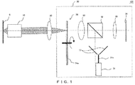
- a fluorescent material is excited and a fluorescence is emitted.
- the fluorescence from the sample S is collected by the objective 10 and the tube lens 20 in the spinning disk 34, and only a fluorescence that has occurred from the position optically conjugate with a slit of the spinning disk 34 passes through the spinning disk 34.
- the fluorescence that has passed through the spinning disk 34 enters the imaging device 36 including a two-dimensional image sensor through the illumination lens 33, the dichroic mirror 32, and the lens 35.
- the spinning disk 34, the illumination lens 33, the dichroic mirror 32, and the reflection member 37 function as a recycling optical system that reuses a laser beam reflected on the reflection surface 34a, which will be described below. This permits a realization of a high illumination efficiency.
- the reflection member 37 is a reflector (a first reflector) that includes two flat mirrors reflecting a beam of light that has entered through the illumination lens 33.
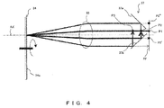
- the reflection member 37 is arranged between the illumination lens 33 and the front focal plane FF of the illumination lens 33 so that a beam of light from the position P1 enters the illumination lens 33 passing between the two flat mirrors.
- the two flat mirrors each have a reflection surface (a reflection surface 37a and a reflection surface 37b) whose respective normal lines have directions that are 90 degrees different with respect to each other in a section along the optical axis AX of the illumination lens 33 (a YZ section of FIG. 5 ) .
- the laser beam reflected on the reflection surface 34a re-enters the spinning disk 34 and is reused. Further, the re-entrance of the laser beam is repeated unless the beam of light reflected on the reflection surface 34a and converged by the illumination lens 33 is deviated from the reflection member 37.
- a position to enter the reflection surfaces (the reflection surface 37a and the reflection surface 37b) of the reflection member 37 is shifted by 2 ⁇ D1 in a Y-axis direction every time the re-entrance is repeated when a distance between an initial entering position of the laser beam (that is, the position P1) and the optical axis AX is D1, as illustrated in FIG. 5 .
- the number of re-entrances is D2/(2 ⁇ D1) when a width of the mirrors in the Y-axis direction that constitute the reflection member 37 is D2.
- the disk scanning apparatus 30 permits a laser beam to re-enter the spinning disk 34 multiple times, which results in realizing a high illumination efficiency.
- the illumination efficiency of the disk scanning apparatus 30 as illustrated in FIGS. 6A to 6D , an about-25-to-30-times-repeated re-entrance of light permits obtaining of an illumination efficiency almost similar to when light re-enters the unlimited number of times, regardless of an disk aperture ratio.
- the disk aperture ratio is a proportion of an area of the apertures in an illuminated area to an area of the illuminated area in the disk.
- the disk scanning apparatus 30 is preferably designed so that D2/(2 ⁇ D1) is about 30.
- the present embodiment illustrates the spinning disk 34 in which the apertures (slits) and the shield portions are alternately formed at a constant pitch.
- the disk scanning apparatus 30 includes a disk in which apertures that function as a confocal aperture are formed, and the disk scanning apparatus 30 may include, for example, a so-called Nipkow disk in which pinholes are formed, instead of the spinning disk 34.
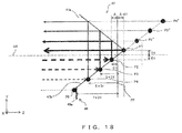
- FIG. 8 illustrates an example of a portion of a configuration of a disk scanning apparatus according to the present embodiment.
- the disk scanning apparatus according to the present embodiment is different from the disk scanning apparatus 30 according to the first embodiment in including a reflection member 40.
- the reflection member 40 has, in the front focal plane FF of the illumination lens 33, a reflection surface 40a perpendicular to the optical axis AX. The others in the configuration are similar to those of the disk scanning apparatus 30.
- the reflection surface 40a of the reflection member 40 is a third reflection surface of the disk scanning apparatus.
- an exit end of the optical fiber 31a (the position P1) is arranged on the front focal plane FF and in a position farther away than the reflection member 41 from the optical axis AX. This permits a laser beam to gradually move from outside to inside the reflection member 41 every time it re-enters the reflection member 41. Then, when getting close to the center, the laser beam moves from the inside to the outside.
- the disk scanning apparatus according to the present embodiment permits doubling of the number of re-entrances. This results in realizing a high illumination efficiency as is the case with the disk scanning apparatus according to the second embodiment. It is also similar to the disk scanning apparatus according to the second embodiment in being able to mitigate a bias in the illumination intensity distribution in the exit pupil plane of the objective 10.
- the flat mirrors When the flat mirrors are narrowly spaced with respect to each other, they may be arranged away from each other in the reflection member 41 as is the case in the reflection member 37.
- the disk scanning apparatus permits suppressing of an angular dependency of the intensity of an illumination light with which the sample S is irradiated while easily realizing a high illumination efficiency.
- FIGS. 11A and 11B illustrate an example of a portion of a configuration of a disk scanning apparatus according to the present embodiment.
- FIG. 11A is a YZ-sectional view
- FIG. 11B illustrates the portion as viewed from a Z-axis direction.
- the disk scanning apparatus according to the present embodiment is different from the disk scanning apparatus according to the second embodiment in arranging the exit end of the optical fiber 31a in the position P1 offset from the optical axis AX not only in the Y-axis direction but also in an X-axis direction.
- the others in the configuration are similar to those of the disk scanning apparatus according to the second embodiment.
- the reflection member 43 includes four flat mirrors. Two of the four flat mirrors each have a reflection surface (a reflection surface 43a and a reflection surface 43b) whose respective normal lines have directions that are 90 degrees different with respect to each other in a section along the optical axis AX. Those two reflection surfaces intersect and are in contact with each other in the front focal plane FF. Further, the remaining two flat mirrors, too, each have a reflection surface (a reflection surface 43c and a reflection surface 43d) whose respective normal lines have directions that are 90 degrees different with respect to each other in a section along the optical axis AX. Those two reflection surfaces intersect and are in contact with each other in the front focal plane FF. In other words, the reflection member 43 is constituted of two reflection member elements each including two flat mirrors.
- the reflection member 43 is arranged between the illumination lens 33 and the front focal plane FF of the illumination lens 33 so that a beam of light from the position P1 enters the illumination lens 33 passing between the two reflection member elements.
- the position P1 is a position obtained by moving from the optical axis AX by a distance D1 in a Y-direction.
- the disk scanning apparatus permits an easy realization of a high illumination efficiency and permits suppressing of an angular dependency of the intensity of an illumination light with which the sample S is irradiated.
- the disk scanning apparatus permits doubling of the number of re-entrances by providing the reflection member 40 on the front focal plane FF. Further, if the position P1 is offset from the optical axis AX not only in the Y-direction but also in an X-direction, a reflection member can be made smaller.
- the reflection member 44 is a conical mirror whose apex is in the position P1 on the front focal plane FF.
- the reflection member 44 is similar to the reflection member 37 in having two reflection surfaces (a reflection surface 44a and a reflection surface 44b) whose respective normal lines have directions that are 90 degrees different with respect to each other in a section along the optical axis AX, those two reflection surfaces intersecting with each other in the front focal plane FF.
- the reflection member 44 does not have power in a YZ-plane, but has power in an XY-plane.
- the laser beam reflected on the reflection surface 34a is not collected on one point and then a point image is not formed, but like the disk scanning apparatus 30, it permits the laser beam to re-enter the spinning disk 34 multiple times.
- the position P1 that is an initial entering position of a laser beam is a position offset by D1 from the optical axis AX of the illumination lens 33, and farther away than the front focal plane FF by ⁇ from the illumination lens 33.
- the illumination lens 33 that constitutes the 4f optical system along with the spinning disk 34 acts so that a light source image formed away than the front focal plane FF from the illumination lens 33 is projected onto a position that is closer than the front focal plane FF to the illumination lens 33.
- the illumination lens 33 and the reflection member 44 are arranged so that the light source image is formed, in a state in which the reflection member 47 is excluded, by the illumination lens 33 in a position that is closer than the front focal plane FF to the illumination lens 33.
- the reflection member 48 is a second reflector that directs, toward the illumination lens 33, the beam of light reflected on the spinning disk 34 and entering through the illumination lens 33.
- the reflection member 48 is similar to the reflection member 40 of the disk scanning apparatus according to the second embodiment in having a reflection surface (a reflection surface 48a) perpendicular to the optical axis AX, and in being arranged in a position which a laser beam deviated from the reflection member 47 as a result of re-entering the spinning disk 34 repeatedly enters. The position is farther away than the reflection member 47 from the optical axis AX. However, there is a difference in that the reflection member 48 is arranged in a position closer than the front focal plane FF to the illumination lens 33, the position is near the reflection member 47.
Landscapes
- Physics & Mathematics (AREA)
- General Physics & Mathematics (AREA)
- Optics & Photonics (AREA)
- Chemical & Material Sciences (AREA)
- Analytical Chemistry (AREA)
- Microscoopes, Condenser (AREA)
Applications Claiming Priority (2)
| Application Number | Priority Date | Filing Date | Title |
|---|---|---|---|
| JP2014255636 | 2014-12-17 | ||
| JP2015196382A JP6579618B2 (ja) | 2014-12-17 | 2015-10-02 | 走査装置、共焦点観察装置、及びディスク走査装置 |
Publications (1)
| Publication Number | Publication Date |
|---|---|
| EP3035101A1 true EP3035101A1 (fr) | 2016-06-22 |
Family
ID=54849845
Family Applications (1)
| Application Number | Title | Priority Date | Filing Date |
|---|---|---|---|
| EP15199858.0A Withdrawn EP3035101A1 (fr) | 2014-12-17 | 2015-12-14 | Appareil de balayage et appareil d'observation confocale |
Country Status (2)
| Country | Link |
|---|---|
| US (1) | US9733462B2 (fr) |
| EP (1) | EP3035101A1 (fr) |
Cited By (2)
| Publication number | Priority date | Publication date | Assignee | Title |
|---|---|---|---|---|
| CN108037075A (zh) * | 2017-11-30 | 2018-05-15 | 哈尔滨工业大学 | 共焦显微镜模式像差矫正方法 |
| WO2018115052A1 (fr) * | 2016-12-23 | 2018-06-28 | Koninklijke Philips N.V. | Capteur de particules et procédé de détection |
Families Citing this family (6)
| Publication number | Priority date | Publication date | Assignee | Title |
|---|---|---|---|---|
| US9581804B1 (en) * | 2014-12-19 | 2017-02-28 | Amazon Technologies, Inc. | Liquid dispensing method for manufacturing an electrowetting device |
| JP6539052B2 (ja) | 2015-01-20 | 2019-07-03 | 浜松ホトニクス株式会社 | 画像取得装置および画像取得方法 |
| JP6300739B2 (ja) * | 2015-01-20 | 2018-03-28 | 浜松ホトニクス株式会社 | 画像取得装置および画像取得方法 |
| KR101715470B1 (ko) * | 2015-04-10 | 2017-03-14 | 충북대학교 산학협력단 | 집적영상 현미경 장치 및 심도범위 개선 방법 |
| CN111344620B (zh) * | 2019-01-25 | 2024-02-13 | 敏捷焦点设计有限责任公司 | 用于宽场、共焦和多光子显微镜的动态聚焦和变焦系统 |
| US11347039B2 (en) | 2019-05-22 | 2022-05-31 | The Boeing Company | Optical imaging and scanning of holes |
Citations (4)
| Publication number | Priority date | Publication date | Assignee | Title |
|---|---|---|---|---|
| JPH04330412A (ja) | 1990-05-23 | 1992-11-18 | Yokogawa Electric Corp | 共焦点用光スキャナ |
| DE102007009551B3 (de) * | 2007-02-27 | 2008-08-21 | Ludwig-Maximilian-Universität | Vorrichtung für die konfokale Beleuchtung einer Probe |
| JP2013015681A (ja) | 2011-07-04 | 2013-01-24 | Olympus Corp | ディスク走査型共焦点観察装置 |
| EP2733514A1 (fr) * | 2012-11-16 | 2014-05-21 | PerkinElmer Cellular Technologies Germany GmbH | Appareil d'éclairage structuré d'un spécimen |
Family Cites Families (1)
| Publication number | Priority date | Publication date | Assignee | Title |
|---|---|---|---|---|
| DE102011000835C5 (de) * | 2011-02-21 | 2019-08-22 | Leica Microsystems Cms Gmbh | Abtastmikroskop und Verfahren zur lichtmikroskopischen Abbildung eines Objektes |
-
2015
- 2015-12-14 EP EP15199858.0A patent/EP3035101A1/fr not_active Withdrawn
- 2015-12-14 US US14/968,498 patent/US9733462B2/en active Active
Patent Citations (5)
| Publication number | Priority date | Publication date | Assignee | Title |
|---|---|---|---|---|
| JPH04330412A (ja) | 1990-05-23 | 1992-11-18 | Yokogawa Electric Corp | 共焦点用光スキャナ |
| DE102007009551B3 (de) * | 2007-02-27 | 2008-08-21 | Ludwig-Maximilian-Universität | Vorrichtung für die konfokale Beleuchtung einer Probe |
| US20080218849A1 (en) | 2007-02-27 | 2008-09-11 | Till I.D. Gmbh | Device for confocal illumination of a specimen |
| JP2013015681A (ja) | 2011-07-04 | 2013-01-24 | Olympus Corp | ディスク走査型共焦点観察装置 |
| EP2733514A1 (fr) * | 2012-11-16 | 2014-05-21 | PerkinElmer Cellular Technologies Germany GmbH | Appareil d'éclairage structuré d'un spécimen |
Cited By (2)
| Publication number | Priority date | Publication date | Assignee | Title |
|---|---|---|---|---|
| WO2018115052A1 (fr) * | 2016-12-23 | 2018-06-28 | Koninklijke Philips N.V. | Capteur de particules et procédé de détection |
| CN108037075A (zh) * | 2017-11-30 | 2018-05-15 | 哈尔滨工业大学 | 共焦显微镜模式像差矫正方法 |
Also Published As
| Publication number | Publication date |
|---|---|
| US20160178880A1 (en) | 2016-06-23 |
| US9733462B2 (en) | 2017-08-15 |
Similar Documents
| Publication | Publication Date | Title |
|---|---|---|
| EP3035101A1 (fr) | Appareil de balayage et appareil d'observation confocale | |
| US20190146201A1 (en) | Structured illuminating apparatus, structured illuminating microscopy apparatus, and structured illuminating method | |
| US9810896B2 (en) | Microscope device and microscope system | |
| US7400446B2 (en) | Confocal microscope | |
| US10108008B2 (en) | Image-forming optical system, illumination apparatus, and observation apparatus | |
| EP3581899A1 (fr) | Microscope spectroscopique et procédé d'observation spectroscopique | |
| US20170160543A1 (en) | Scanning projector transmissive screen, and scanning projector system | |
| US7369309B2 (en) | Confocal microscope | |
| CN103339547A (zh) | 扫描显微镜和用于物体的光显微成像的方法 | |
| JP2009103958A (ja) | 走査型レーザ顕微鏡 | |
| JP2008250303A (ja) | シート光を発生するための光学装置 | |
| JP7109423B2 (ja) | ライトシート顕微鏡 | |
| US10983327B2 (en) | Light sheet microscope | |
| EP2977809A1 (fr) | Élément d'éclairage optique, système optique d'éclairage et appareil d'éclairage | |
| EP3779556B1 (fr) | Dispositif d'éclairage optique | |
| WO2015098242A1 (fr) | Dispositif d'observation d'échantillon et procédé d'observation d'échantillon | |
| US20170192217A1 (en) | Optical-axis-direction scanning microscope apparatus | |
| JP2016212154A (ja) | 走査型顕微鏡システム | |
| WO2017077777A1 (fr) | Dispositif d'acquisition d'image, procédé d'acquisition d'image, et unité de modulation spatiale de lumière | |
| JP2007286310A (ja) | 光学装置及び結像方法 | |
| US20130286182A1 (en) | Focus position maintaining apparatus, and microscope | |
| JP2004317741A (ja) | 顕微鏡およびその光学調整方法 | |
| JP6579618B2 (ja) | 走査装置、共焦点観察装置、及びディスク走査装置 | |
| JP5929204B2 (ja) | 走査型顕微鏡 | |
| EP2733514B1 (fr) | Appareil microscopique permettant l'éclairage structuré d'un spécimen |
Legal Events
| Date | Code | Title | Description |
|---|---|---|---|
| PUAI | Public reference made under article 153(3) epc to a published international application that has entered the european phase |
Free format text: ORIGINAL CODE: 0009012 |
|
| AK | Designated contracting states |
Kind code of ref document: A1 Designated state(s): AL AT BE BG CH CY CZ DE DK EE ES FI FR GB GR HR HU IE IS IT LI LT LU LV MC MK MT NL NO PL PT RO RS SE SI SK SM TR |
|
| AX | Request for extension of the european patent |
Extension state: BA ME |
|
| RAP1 | Party data changed (applicant data changed or rights of an application transferred) |
Owner name: OLYMPUS CORPORATION |
|
| RAP1 | Party data changed (applicant data changed or rights of an application transferred) |
Owner name: OLYMPUS CORPORATION |
|
| RIN1 | Information on inventor provided before grant (corrected) |
Inventor name: YAMAZAKI, KENTARO |
|
| 17P | Request for examination filed |
Effective date: 20161013 |
|
| RBV | Designated contracting states (corrected) |
Designated state(s): AL AT BE BG CH CY CZ DE DK EE ES FI FR GB GR HR HU IE IS IT LI LT LU LV MC MK MT NL NO PL PT RO RS SE SI SK SM TR |
|
| STAA | Information on the status of an ep patent application or granted ep patent |
Free format text: STATUS: EXAMINATION IS IN PROGRESS |
|
| 17Q | First examination report despatched |
Effective date: 20190619 |
|
| STAA | Information on the status of an ep patent application or granted ep patent |
Free format text: STATUS: THE APPLICATION IS DEEMED TO BE WITHDRAWN |
|
| 18D | Application deemed to be withdrawn |
Effective date: 20191030 |