EP3034976B1 - Installation for drying a wet non-woven web - Google Patents
Installation for drying a wet non-woven web Download PDFInfo
- Publication number
- EP3034976B1 EP3034976B1 EP15192832.2A EP15192832A EP3034976B1 EP 3034976 B1 EP3034976 B1 EP 3034976B1 EP 15192832 A EP15192832 A EP 15192832A EP 3034976 B1 EP3034976 B1 EP 3034976B1
- Authority
- EP
- European Patent Office
- Prior art keywords
- inlet
- installation according
- perforated sheet
- conduit
- oven
- Prior art date
- Legal status (The legal status is an assumption and is not a legal conclusion. Google has not performed a legal analysis and makes no representation as to the accuracy of the status listed.)
- Active
Links
- 238000001035 drying Methods 0.000 title claims description 20
- 238000009434 installation Methods 0.000 title claims description 16
- 238000009792 diffusion process Methods 0.000 claims description 14
- 239000011800 void material Substances 0.000 claims description 12
- 238000011144 upstream manufacturing Methods 0.000 claims description 10
- 239000004744 fabric Substances 0.000 claims description 4
- 238000010438 heat treatment Methods 0.000 claims description 3
- 230000007423 decrease Effects 0.000 claims 1
- 238000006073 displacement reaction Methods 0.000 claims 1
- 235000021183 entrée Nutrition 0.000 description 9
- 238000004891 communication Methods 0.000 description 6
- 238000000605 extraction Methods 0.000 description 3
- XEEYBQQBJWHFJM-UHFFFAOYSA-N Iron Chemical compound [Fe] XEEYBQQBJWHFJM-UHFFFAOYSA-N 0.000 description 2
- PXHVJJICTQNCMI-UHFFFAOYSA-N Nickel Chemical group [Ni] PXHVJJICTQNCMI-UHFFFAOYSA-N 0.000 description 2
- 230000003247 decreasing effect Effects 0.000 description 2
- 238000001914 filtration Methods 0.000 description 2
- 238000004519 manufacturing process Methods 0.000 description 2
- 238000000034 method Methods 0.000 description 2
- XLYOFNOQVPJJNP-UHFFFAOYSA-N water Substances O XLYOFNOQVPJJNP-UHFFFAOYSA-N 0.000 description 2
- 239000012141 concentrate Substances 0.000 description 1
- 230000007547 defect Effects 0.000 description 1
- 230000006735 deficit Effects 0.000 description 1
- 238000009795 derivation Methods 0.000 description 1
- 239000003344 environmental pollutant Substances 0.000 description 1
- 239000000835 fiber Substances 0.000 description 1
- 229910052742 iron Inorganic materials 0.000 description 1
- 238000012423 maintenance Methods 0.000 description 1
- 229910052759 nickel Inorganic materials 0.000 description 1
- 239000002245 particle Substances 0.000 description 1
- 231100000719 pollutant Toxicity 0.000 description 1
- 230000001105 regulatory effect Effects 0.000 description 1
- 238000010792 warming Methods 0.000 description 1
Images


Classifications
-
- D—TEXTILES; PAPER
- D21—PAPER-MAKING; PRODUCTION OF CELLULOSE
- D21F—PAPER-MAKING MACHINES; METHODS OF PRODUCING PAPER THEREON
- D21F5/00—Dryer section of machines for making continuous webs of paper
- D21F5/18—Drying webs by hot air
-
- F—MECHANICAL ENGINEERING; LIGHTING; HEATING; WEAPONS; BLASTING
- F26—DRYING
- F26B—DRYING SOLID MATERIALS OR OBJECTS BY REMOVING LIQUID THEREFROM
- F26B21/00—Arrangements or duct systems, e.g. in combination with pallet boxes, for supplying and controlling air or gases for drying solid materials or objects
- F26B21/001—Drying-air generating units, e.g. movable, independent of drying enclosure
-
- F—MECHANICAL ENGINEERING; LIGHTING; HEATING; WEAPONS; BLASTING
- F26—DRYING
- F26B—DRYING SOLID MATERIALS OR OBJECTS BY REMOVING LIQUID THEREFROM
- F26B13/00—Machines and apparatus for drying fabrics, fibres, yarns, or other materials in long lengths, with progressive movement
- F26B13/10—Arrangements for feeding, heating or supporting materials; Controlling movement, tension or position of materials
- F26B13/14—Rollers, drums, cylinders; Arrangement of drives, supports, bearings, cleaning
- F26B13/16—Rollers, drums, cylinders; Arrangement of drives, supports, bearings, cleaning perforated in combination with hot air blowing or suction devices, e.g. sieve drum dryers
-
- F—MECHANICAL ENGINEERING; LIGHTING; HEATING; WEAPONS; BLASTING
- F26—DRYING
- F26B—DRYING SOLID MATERIALS OR OBJECTS BY REMOVING LIQUID THEREFROM
- F26B21/00—Arrangements or duct systems, e.g. in combination with pallet boxes, for supplying and controlling air or gases for drying solid materials or objects
- F26B21/004—Nozzle assemblies; Air knives; Air distributors; Blow boxes
-
- F—MECHANICAL ENGINEERING; LIGHTING; HEATING; WEAPONS; BLASTING
- F26—DRYING
- F26B—DRYING SOLID MATERIALS OR OBJECTS BY REMOVING LIQUID THEREFROM
- F26B21/00—Arrangements or duct systems, e.g. in combination with pallet boxes, for supplying and controlling air or gases for drying solid materials or objects
- F26B21/02—Circulating air or gases in closed cycles, e.g. wholly within the drying enclosure
- F26B21/04—Circulating air or gases in closed cycles, e.g. wholly within the drying enclosure partly outside the drying enclosure
-
- F—MECHANICAL ENGINEERING; LIGHTING; HEATING; WEAPONS; BLASTING
- F26—DRYING
- F26B—DRYING SOLID MATERIALS OR OBJECTS BY REMOVING LIQUID THEREFROM
- F26B21/00—Arrangements or duct systems, e.g. in combination with pallet boxes, for supplying and controlling air or gases for drying solid materials or objects
- F26B21/06—Controlling, e.g. regulating, parameters of gas supply
- F26B21/12—Velocity of flow; Quantity of flow, e.g. by varying fan speed, by modifying cross flow area
-
- F—MECHANICAL ENGINEERING; LIGHTING; HEATING; WEAPONS; BLASTING
- F26—DRYING
- F26B—DRYING SOLID MATERIALS OR OBJECTS BY REMOVING LIQUID THEREFROM
- F26B23/00—Heating arrangements
- F26B23/001—Heating arrangements using waste heat
- F26B23/002—Heating arrangements using waste heat recovered from dryer exhaust gases
-
- Y—GENERAL TAGGING OF NEW TECHNOLOGICAL DEVELOPMENTS; GENERAL TAGGING OF CROSS-SECTIONAL TECHNOLOGIES SPANNING OVER SEVERAL SECTIONS OF THE IPC; TECHNICAL SUBJECTS COVERED BY FORMER USPC CROSS-REFERENCE ART COLLECTIONS [XRACs] AND DIGESTS
- Y02—TECHNOLOGIES OR APPLICATIONS FOR MITIGATION OR ADAPTATION AGAINST CLIMATE CHANGE
- Y02P—CLIMATE CHANGE MITIGATION TECHNOLOGIES IN THE PRODUCTION OR PROCESSING OF GOODS
- Y02P70/00—Climate change mitigation technologies in the production process for final industrial or consumer products
- Y02P70/10—Greenhouse gas [GHG] capture, material saving, heat recovery or other energy efficient measures, e.g. motor control, characterised by manufacturing processes, e.g. for rolling metal or metal working
Definitions
- the present invention relates to drying facilities of a nonwoven web.
- the US 6,551,461 B2 a method of drying a wet web is described by passing warm air through an oven through a wet web, which is moved by a means of transport, thereby warming it by heating a first portion of the humidified air and by making it iron in the oven through the wet web and by making in a drying device, upstream of the oven in the direction of movement of the web, through the wet web moved, a second part of the humidified air.
- the nonwoven web thus obtained is not dried in a uniform manner.
- the current is uniformized air passing through the wet web and, as a result, the moisture of the nonwoven web exiting the installation.
- the perforations of the first perforated plate preferably have a diameter of 2 to 8 mm, and more preferably 2 to 4 mm.
- the thickness of this sheet is preferably from 1 to 3 mm (the best is 1.5 mm).
- Vacuum rate means the ratio of the open area of the sheet to the total area.
- the void ratio is between 10% and 60%. Particularly good standardization was obtained when the vacuum of the first perforated plate goes from 40 to 60% on the side of the entrance of the diffusion box, where it is the largest, at 10 to 20% opposite the entry where it is the smallest . It is preferred that the ratio between these void ratios be 1/4 to 1/6 and in particular about 1/5.
- the box and the connection have the same length and the same width. They can be in the form of parallelepipeds.
- the entry into the diffusion box is made by a small front side, which simplifies the manufacture of the box.
- connection can be flanged to a channel, in which is mounted a honeycomb beam, preferably supported by a second perforated plate having a higher void rate than the first perforated plate and 40% at 60%, whose cell size is greater than that of the perforations of the first perforated plate and a length of 30 to 100 mm, preferably 40 to 60 mm.
- the equivalent diameter of a cell is between 3 and 10 mm, preferably between 4 and 6 mm.
- the cells are preferably of hexagonal cross-section.
- the length that is to say, the dimension in the direction of passage of the air in the honeycomb or the axis of the channel
- D equivalent of the honeycomb 10
- the honeycomb beam directs the flow parallel to the direction of the channel and thus maximizes the transfer of diffusion air towards the suction box. But the pollutant particles from fiber clusters released by the fan pollute the honeycomb and cause defects of homogeneity of the flow as the fouling of the honeycomb.
- the first perforated plate also plays a role in filtration, avoiding pollution of the honeycomb beam and the nonwoven web.
- the first perforated plate can also advantageously be covered with a wire cloth whose perforation dimensions are smaller than those of the first perforated sheet, for example whose perforations have a size of 0.1 to 1 mm and having a void ratio of between 25% and 50% and a thickness of between 0.5 and 2 mm, which ensures even better filtration and prevents pollution of the nonwoven.
- the first perforated sheet that clogs up faster. Therefore, it is intended, according to one embodiment of the invention, to mount it in a removable connector drawer, which preferably has a handle on the outside of the connector.
- a removable connector drawer which preferably has a handle on the outside of the connector.
- To replace the first perforated plate it is no longer necessary to unclamp the channel connection. Simply remove the drawer in which the first perforated plate is mounted, remove the first perforated plate of the drawer, clean it, then put it back in the drawer or put a new one and put the drawer back into place. the fitting. The maintenance of the installation is greatly facilitated.
- the honeycomb can be mounted on a drawer that can be pulled out independently of the other drawer.
- the dried web 1 circulates around a drum 2 or on a conveyor.
- An inlet conduit C1 for supplying pressurized hot air is injected into the hood 3 by means of a fan V1 6 (called the main fan) and a heat source 4 which heats the air.
- This heat source 4 may be for example a gas burner or a heat exchanger (oil, air, water or electric).
- This hot air then passes through the wet web and the drum 2 (or the web of the conveyor): by this method, the water contained in the web is evaporated as the web advances on the drum 2 (or on the web). conveyor).
- the air that has passed through the veil has cooled down and has become wet. It is then sucked by a conduit C2 extraction inside the drum 2 by the fan V1 6, and reheated by the heat source 4 and reinjected into the loop and so on.
- the heat source 4 can be placed upstream or downstream of the fan V1 6. Preferably, it is placed downstream as described in the figure, in the case of an exchanger and upstream in the case of a burner. gas.
- the motor of this fan V1 6 is controlled by a frequency converter 14.
- the temperature of the hot air injected into the hood 3 is regulated by the action of the heat source 4.
- Part of the cooled and humid air is discharged outside the loop so as not to concentrate the moisture in the circulation loop.
- Part of the cooled and humid air is therefore evacuated via the bypass duct C3 by virtue of the pressure generated at the outlet by the fan V1 (6) if it is sufficient or by virtue of an additional bypass ventilator V2 (8).
- the bypass conduit C3 can be connected upstream of V1.
- Flaps 9 bis can be installed in the conduit C3 bypass so as to regulate the value of the extracted flow.
- the cooled and wet air discharged through the bypass conduit C3 is then injected into a diffusion box 10 which will diffuse air over a drying crate 11 located upstream of the furnace 3, on which the sail to dry.
- the air is sucked into the drying box 11 by a final exhaust fan V3 12.
- this fan 12 is positioned closest to the drying box 11.
- the distribution fund represented figures 2 and 3 comprises a parallelepipedal box 9 having two end faces, one of which is closed and the other of which receives the inlet 13 at the inlet. From the large lower face, a parallelepipedic connection 21 of the same length as the box.
- the width of the box 9 is the same as the width of the fitting 21.
- the width L of the fitting 21 is from 400 to 1200 mm.
- this connection 21 is mounted a sliding removable slide 22 having a handle 23 and carrying a perforated first sheet 24 having a void ratio of 10 to 60%.
- the slide 22 slides in the fitting 21 by slideways 25.
- the first perforated plate 24 is covered with a thin wire cloth having a void ratio of 25 to 50%.
- a channel 27 in which is mounted a beam 28 honeycomb, supported by a second perforated plate 29 having a vacuum content of 40 to 60%.
- the cells of the honeycomb beam 28 have an equivalent diameter of the circle inscribed in the hexagon of 4 to 10 mm.
- the figure 4 shows that the first perforated plate 24 has a vacuum rate gradient.
- the right part of the first sheet has a higher void rate than the left part.
- the right part has a vacuum rate of 40 to 60%.
- the left side has a vacuum rate of 10 to 20%.
- the variation of the vacuum ratio from right to left can be done progressively or in steps. This variation can be obtained by the same number of perforations but whose dimensions grow from right to left or by perforations of the same dimensions, but in different numbers.
- the figure 5 is a view similar to the figure 2 a diffusion box in which the honeycomb beam 28 is mounted on a removable drawer 31.
Landscapes
- Engineering & Computer Science (AREA)
- Mechanical Engineering (AREA)
- General Engineering & Computer Science (AREA)
- Textile Engineering (AREA)
- Life Sciences & Earth Sciences (AREA)
- Sustainable Development (AREA)
- Drying Of Solid Materials (AREA)
- Treatment Of Fiber Materials (AREA)
- Nonwoven Fabrics (AREA)
Description
La présente invention se rapporte aux installations de séchage d'un voile de non-tissé.The present invention relates to drying facilities of a nonwoven web.
Au
On constate que le voile de non-tissé ainsi obtenu n'est pas séché d'une manière uniforme.It is found that the nonwoven web thus obtained is not dried in a uniform manner.
L'invention y remédie par une installation de séchage d'un voile de non-tissé caractérisée en ce qu'elle comprend :
- un ventilateur,
- un four de chauffage ayant une entrée et une sortie,
- un conduit d'entrée qui met le refoulement du ventilateur en communication avec l'entrée du four et envoie de l'air refoulé à l'entrée du four,
- une source de chaleur disposée de manière à ce que l'air refoulé dans le conduit d'entrée soit chauffé,
- un conduit de sortie qui met la sortie du four en communication avec l'aspiration du ventilateur,
- un conduit de dérivation, en dérivation du conduit d'entrée en amont de la source de chaleur, mettant le conduit d'entrée en communication avec l'entrée d'un dispositif de séchage,
- un moyen de transport qui déplace un voile dans le dispositif de séchage et dans le four, le dispositif de séchage étant en amont du four dans le sens de déplacement du voile,
- un conduit d'extraction de l'air du dispositif de séchage,
- le dispositif de séchage comprend un caisson de diffusion ayant un raccord de sortie dans lequel est montée une première tôle perforée ayant un gradient de taux de vide décroissant à partir de l'endroit le plus proche de l'entrée du caisson, de préférence compris entre 10 % et 60 %.
- a fan,
- a heating furnace having an inlet and an outlet,
- an inlet duct which puts the discharge of the fan in communication with the furnace inlet and sends discharge air to the furnace inlet,
- a heat source arranged in such a way that the air discharged into the inlet duct is heated,
- an outlet duct which puts the furnace outlet in communication with the suction of the fan,
- a bypass duct, in derivation of the inlet duct upstream of the heat source, the inlet duct in communication with the inlet of a drying device,
- a transport means which moves a web in the drying device and in the oven, the drying device being upstream of the oven in the direction of movement of the web,
- an air extraction duct of the drying device,
- the drying device comprises a diffusion box having an outlet connection in which is mounted a first perforated plate having a gradient of decreasing vacuum rate from the nearest point of the inlet of the box, preferably between 10% and 60%.
En montant une première tôle perforée créant une perte de charge dans le raccord de sortie du caisson de diffusion, et en donnant à la tôle perforée un gradient de taux de vide décroissant à partir de l'entrée du caisson de diffusion, on uniformise le courant d'air passant à travers le voile humide et, en conséquence, l'humidité du voile de non-tissé sortant de l'installation.By mounting a first perforated sheet creating a pressure drop in the outlet connection of the diffusion box, and by giving the perforated sheet a gradient of decreasing vacuum rate from the inlet of the diffusion box, the current is uniformized air passing through the wet web and, as a result, the moisture of the nonwoven web exiting the installation.
Les perforations de la première tôle perforée ont de préférence un diamètre de 2 à 8 mm, et mieux de 2 à 4 mm. L'épaisseur de cette tôle va de préférence de 1 à 3 mm (le mieux est 1,5 mm).The perforations of the first perforated plate preferably have a diameter of 2 to 8 mm, and more preferably 2 to 4 mm. The thickness of this sheet is preferably from 1 to 3 mm (the best is 1.5 mm).
Par taux de vide, on entend le rapport de la surface ouverte de la tôle à la surface totale. De préférence, le taux de vide est compris entre 10% et 60%. On a obtenu une uniformisation particulièrement bonne lorsque le taux de vide de la première tôle perforée va de 40 à 60 % du côté de l'entrée du caisson de diffusion, où il est le plus grand, à 10 à 20% à l'opposé de l'entrée où il est le plus petit. On préfère que le rapport entre ces taux de vide soit 1/4 à 1/6 et soit notamment d'environ 1/5.Vacuum rate means the ratio of the open area of the sheet to the total area. Preferably, the void ratio is between 10% and 60%. Particularly good standardization was obtained when the vacuum of the first perforated plate goes from 40 to 60% on the side of the entrance of the diffusion box, where it is the largest, at 10 to 20% opposite the entry where it is the smallest . It is preferred that the ratio between these void ratios be 1/4 to 1/6 and in particular about 1/5.
Le caisson comme le raccord ont notamment la même longueur et la même largeur. Ils peuvent se présenter sous la forme de parallélépipèdes. De préférence, l'entrée dans le caisson de diffusion s'effectue par un petit côté frontal, ce qui simplifie la fabrication du caisson.The box and the connection have the same length and the same width. They can be in the form of parallelepipeds. Preferably, the entry into the diffusion box is made by a small front side, which simplifies the manufacture of the box.
Suivant un perfectionnement, le raccord peut être bridé à un canal, dans lequel est monté un faisceau en nid d'abeille, de préférence supporté par une deuxième tôle perforée ayant un taux de vide supérieur à celui de la première tôle perforée et de 40% à 60%, dont la dimension des alvéoles est plus grande que celle des perforations de la première tôle perforée et d'une longueur de 30 à 100 mm, de préférence de 40 à 60 mm. Le diamètre équivalent d'un alvéole est compris entre 3 et 10 mm, de préférence entre 4 et 6 mm. Le diamètre équivalent D se calcule par ![]()
![]()
C'est maintenant la première tôle perforée qui s'encrasse le plus vite. C'est pourquoi, il est prévu, suivant un mode de réalisation de l'invention, de la monter dans un tiroir amovible de raccord, qui a de préférence une poignée à l'extérieur du raccord. Pour remplacer la première tôle perforée, il n'est plus nécessaire de débrider le raccord du canal. Il suffit de sortir le tiroir dans lequel la première tôle perforée est montée, de sortir la première tôle perforée du tiroir, de la nettoyer, puis de la remettre dans le tiroir ou d'en mettre une neuve et de remettre le tiroir en place dans le raccord. L'entretien de l'installation est grandement facilité. De la même façon, le nid d'abeille peut être monté sur un tiroir qui peut être sorti indépendamment de l'autre tiroir.It is now the first perforated sheet that clogs up faster. Therefore, it is intended, according to one embodiment of the invention, to mount it in a removable connector drawer, which preferably has a handle on the outside of the connector. To replace the first perforated plate, it is no longer necessary to unclamp the channel connection. Simply remove the drawer in which the first perforated plate is mounted, remove the first perforated plate of the drawer, clean it, then put it back in the drawer or put a new one and put the drawer back into place. the fitting. The maintenance of the installation is greatly facilitated. In the same way, the honeycomb can be mounted on a drawer that can be pulled out independently of the other drawer.
Aux dessins annexés, donnés uniquement à titre d'exemples :
- La
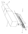
figure 1 illustre l'installation suivant l'invention, - La
figure 2 est une vue en perspective de la caisse de diffusion, - La
figure 3 en est une vue en élévation, - La
figure 4 est une vue en perspective de la tôle perforée, et - La
figure 5 est une vue en perspective d'une autre caisse de diffusion.
- The
figure 1 illustrates the installation according to the invention, - The
figure 2 is a perspective view of the cashbox, - The
figure 3 is an elevation view, - The
figure 4 is a perspective view of the perforated plate, and - The
figure 5 is a perspective view of another pay station.
A la
On injecte par un conduit C1 d'entrée de l'air chaud sous pression dans la hotte 3 grâce à un ventilateur V1 6 (appelé ventilateur principal) et à une source de chaleur 4 qui réchauffe l'air. Cette source de chaleur 4 peut être par exemple un brûleur à gaz ou un échangeur thermique (à huile, air, eau ou électrique).An inlet conduit C1 for supplying pressurized hot air is injected into the
Cet air chaud traverse ensuite le voile humide et le tambour 2 (ou la toile du convoyeur) : par ce procédé, l'eau contenue dans le voile est évaporée au fur et à mesure que le voile avance sur le tambour 2 (ou sur le convoyeur). L'air qui a traversé le voile s'est refroidi et s'est chargé en humidité. Il est alors aspiré par un conduit C2 d'extraction à l'intérieur du tambour 2 par le ventilateur V1 6, et à nouveau réchauffé par la source de chaleur 4 et réinjecté dans la boucle et ainsi de suite. La source de chaleur 4 peut être placée en amont ou en aval du ventilateur V1 6. De préférence, elle est placée en aval comme décrit sur la figure, dans le cas d'un échangeur et en amont dans le cas d'un brûleur à gaz.This hot air then passes through the wet web and the drum 2 (or the web of the conveyor): by this method, the water contained in the web is evaporated as the web advances on the drum 2 (or on the web). conveyor). The air that has passed through the veil has cooled down and has become wet. It is then sucked by a conduit C2 extraction inside the
Le moteur de ce ventilateur V1 6 est piloté par un variateur de fréquence 14.The motor of this fan V1 6 is controlled by a
La température de l'air chaud injecté dans la hotte 3 est régulée par l'action de la source de chaleur 4.The temperature of the hot air injected into the
Une partie de l'air refroidi et humide est évacué à l'extérieur de la boucle afin de ne pas concentrer l'humidité dans la boucle de circulation. On évacue donc une partie de l'air refroidi et humide par le conduit C3 de dérivation grâce à la pression générée en sortie par le ventilateur V1 (6) si elle est suffisante ou grâce à un ventilateur de dérivation supplémentaire V2 (8).Part of the cooled and humid air is discharged outside the loop so as not to concentrate the moisture in the circulation loop. Part of the cooled and humid air is therefore evacuated via the bypass duct C3 by virtue of the pressure generated at the outlet by the fan V1 (6) if it is sufficient or by virtue of an additional bypass ventilator V2 (8).
Le conduit C3 de dérivation peut être connecté en amont de V1.The bypass conduit C3 can be connected upstream of V1.
Des volets 9 bis peuvent être installés dans le conduit C3 de dérivation afin de pouvoir réguler la valeur du débit extrait.
Dans le cas où il y a un ventilateur de dérivation V2 (8), le moteur de ce ventilateur peut être piloté par variateur de fréquence. S'il y a des volets de réglage 9, ce pilotage par variateur n'est pas nécessaire.In the case where there is a branch fan V2 (8), the motor of this fan can be controlled by frequency converter. If there are
Pour combler ce déficit d'air dans la boucle, on aspire dans la salle de production de l'air d'appoint en amont du ventilateur V1 par la tuyauterie 7 d'appoint.To fill this air deficit in the loop, it draws in the production room of makeup air upstream of the fan V1 by the
L'air refroidi et humide évacué par le conduit C3 de dérivation est injecté ensuite dans une caisse de diffusion 10 qui va diffuser l'air au-dessus d'une caisse aspirante de séchage 11 localisée en amont du four 3, sur laquelle circule le voile à sécher.The cooled and wet air discharged through the bypass conduit C3 is then injected into a
Cette caisse aspirante de séchage 11 peut être localisée soit dans un convoyeur (support voile = toile de convoyeur), soit dans un cylindre (support voile = cylindre nickel, tôle perforée, toile métallique).This drying crate 11 can be located either in a conveyor (sail carrier = conveyor belt) or in a cylinder (sail carrier = nickel cylinder, perforated sheet, wire mesh).
L'air est aspiré dans la caisse de séchage 11 par un ventilateur d'extraction final V3 12. De préférence, ce ventilateur 12 est positionné au plus proche de la caisse de séchage 11.The air is sucked into the drying box 11 by a final
La caisse de diffusion représentée aux
Au raccord 21 est bridé, par des brides 26, un canal 27, dans lequel est monté un faisceau 28 en nid d'abeille, supporté par une deuxième tôle 29 perforée ayant un taux de vide de 40 à 60%. Les alvéoles du faisceau 28 en nid d'abeille ont un diamètre équivalent du cercle inscrit dans l'hexagone de 4 à 10 mm.At the
La
A la
La
Claims (10)
- An installation for drying a non-woven web which comprises:- a fan (6),- a heating oven (3) having an inlet and an outlet,- an inlet conduit (C1) which connects the delivery of the fan (6) with the inlet of the oven (3) and sends delivered air to the inlet of the oven,- a heat source (4) arranged in such a way that the air delivered in the inlet conduit (C1) is heated,- an outlet conduit (C2) which connects the outlet of the oven (3) with the intake of the fan (6),- a branch conduit (C3), in the branch of the inlet conduit (C1) upstream of the heat source (4), connecting the inlet conduit (C1) with the inlet of the drying device (10, 11),- a means of transport (2) which displaces a web in the drying device (10, 11) and in the oven (3), the drying device (10, 11) being upstream of the oven (3) in the direction of displacement of the web and- a conduit (C4) for extracting the air from the drying device (10, 11),characterised in that- a drying device comprising a diffusion chamber (10) having an outlet fitting (21) in which is mounted a perforated sheet (24) and- the perforated sheet (24) has a void rate which decreases from the inlet of the diffusion chamber (10) .
- The installation according to claim 1, characterised in that the perforated sheet (24) has a void rate between 10% and 60%.
- The installation according to claim 1 or 2, characterised in that the perforated sheet (24) is mounted in a movable drawer (22) with a handle outside the fitting (21).
- The installation according to anyone of claims 1 to 3, characterised in that the void rate in the perforated sheet (24) ranger from 40% to 60% from the side of the inlet of the diffusion chamber (10), where it is the highest to 10% to 20%.
- The installation according to any one of the preceding claims, characterised in that the perforated sheet (24) is covered with a thin metallic cloth (30) having a void rate between 25% and 50%.
- The installation according to claim 5, characterised in that a dimension of the perforation of the cloth are from 0.1 mm to 1 mm.
- The installation according to any one of the preceding claims, characterised in that downstream of the perforated sheet (24) is mounted in the outlet fitting (21) or in a channel (27) which is clamped to the fitting (21) a honeycombed bundle (28), the dimension of whose cells is greater than that of the perforations of the perforated sheet (24).
- The installation according to claim 6, characterised in that the bundle (28) is supported by a second perforated sheet (29) having a void rate that is greater than 40% to 60%.
- The installation according to claim 6 or 7, characterised in that the bundle (28) is mounted in a movable drawer (31).
- The installation according to claim 7, 8 or 9, characterised in that the ratio of the honeycomb length to the equivalent diameter of the honeycomb is greater than 10.
Priority Applications (1)
| Application Number | Priority Date | Filing Date | Title |
|---|---|---|---|
| EP16187858.2A EP3141853B1 (en) | 2014-12-17 | 2015-11-03 | Installation for drying a wet non-woven web |
Applications Claiming Priority (1)
| Application Number | Priority Date | Filing Date | Title |
|---|---|---|---|
| FR1402884A FR3030705A1 (en) | 2014-12-17 | 2014-12-17 | INSTALLATION FOR DRYING A WET NON-WOVEN NET |
Related Child Applications (2)
| Application Number | Title | Priority Date | Filing Date |
|---|---|---|---|
| EP16187858.2A Division EP3141853B1 (en) | 2014-12-17 | 2015-11-03 | Installation for drying a wet non-woven web |
| EP16187858.2A Division-Into EP3141853B1 (en) | 2014-12-17 | 2015-11-03 | Installation for drying a wet non-woven web |
Publications (3)
| Publication Number | Publication Date |
|---|---|
| EP3034976A2 EP3034976A2 (en) | 2016-06-22 |
| EP3034976A3 EP3034976A3 (en) | 2016-08-17 |
| EP3034976B1 true EP3034976B1 (en) | 2019-01-09 |
Family
ID=52684282
Family Applications (2)
| Application Number | Title | Priority Date | Filing Date |
|---|---|---|---|
| EP15192832.2A Active EP3034976B1 (en) | 2014-12-17 | 2015-11-03 | Installation for drying a wet non-woven web |
| EP16187858.2A Active EP3141853B1 (en) | 2014-12-17 | 2015-11-03 | Installation for drying a wet non-woven web |
Family Applications After (1)
| Application Number | Title | Priority Date | Filing Date |
|---|---|---|---|
| EP16187858.2A Active EP3141853B1 (en) | 2014-12-17 | 2015-11-03 | Installation for drying a wet non-woven web |
Country Status (5)
| Country | Link |
|---|---|
| US (2) | US9765480B2 (en) |
| EP (2) | EP3034976B1 (en) |
| CN (1) | CN105716409B (en) |
| FR (1) | FR3030705A1 (en) |
| IL (2) | IL243052B (en) |
Cited By (1)
| Publication number | Priority date | Publication date | Assignee | Title |
|---|---|---|---|---|
| US10739072B2 (en) * | 2018-05-31 | 2020-08-11 | Valmet, Inc. | Through air drying and bonding systems and methods for maintaining uniform supply air temperature |
Families Citing this family (9)
| Publication number | Priority date | Publication date | Assignee | Title |
|---|---|---|---|---|
| FR3030705A1 (en) * | 2014-12-17 | 2016-06-24 | Andritz Perfojet Sas | INSTALLATION FOR DRYING A WET NON-WOVEN NET |
| DE202015106039U1 (en) * | 2015-11-10 | 2017-02-13 | Autefa Solutions Germany Gmbh | treatment facility |
| US10240292B2 (en) * | 2016-02-29 | 2019-03-26 | Kimberly-Clark Worldwide, Inc. | Through-air drying apparatus and methods of manufacture |
| JP7107661B2 (en) * | 2017-10-31 | 2022-07-27 | 三菱重工業株式会社 | Nozzle for additive manufacturing and additive manufacturing apparatus |
| HUE062427T2 (en) * | 2018-03-29 | 2023-11-28 | Toray Industries | Gas blowout nozzle and furnace, and method for manufacturing processed film |
| DE102019126591A1 (en) * | 2019-10-02 | 2021-04-08 | Voith Patent Gmbh | Device and method for applying process air |
| JP7396207B2 (en) * | 2020-06-03 | 2023-12-12 | トヨタ自動車株式会社 | Electrode plate dryer |
| CN113755983B (en) * | 2021-08-27 | 2022-05-24 | 安徽旭之杰纺织科技有限公司 | Sectional type yarn heating equipment for yarn production |
| CN117781637B (en) * | 2024-02-26 | 2024-05-03 | 云南省林业和草原科学院 | Circulating hot air oven for processing rhizoma polygonati yunnanensis and rhizoma bletillae slices |
Family Cites Families (26)
| Publication number | Priority date | Publication date | Assignee | Title |
|---|---|---|---|---|
| FR1182636A (en) * | 1956-09-12 | 1959-06-26 | Spooner Dryer & Eng Co Ltd | Apparatus for convection treatment in a gaseous fluid |
| US3525164A (en) * | 1968-12-10 | 1970-08-25 | Wolverine Corp | Apparatus for gaseous treatment of moving webs |
| US3879858A (en) * | 1971-07-29 | 1975-04-29 | Robert R Candor | Method and apparatus for treating porous material with fluid |
| US4481722A (en) * | 1982-06-23 | 1984-11-13 | Kimberly-Clark Corporation | System for protecting a rotary dryer from thermal stress |
| SE470134B (en) * | 1992-04-23 | 1993-11-15 | Valmet Karlstad Ab | Ways of converting a conventional tissue machine to a TAD machine, as well as a suitable "C-wrap" type double wire former |
| FR2732044B1 (en) * | 1995-03-20 | 1997-04-30 | Kaysersberg Sa | METHOD FOR WRINGING A SHEET OF CELLULOSIC MATERIAL BY HOT AIR PASSING THROUGH UNDER A HIGH VACUUM |
| DE19517911A1 (en) | 1995-05-16 | 1996-11-21 | Sgl Technik Gmbh | Process for converting multi-dimensional sheet-like structures consisting of polyacrylonitrile fibers into the thermally stabilized state |
| JP3299429B2 (en) * | 1995-12-13 | 2002-07-08 | 松下電器産業株式会社 | Battery electrode drying equipment |
| US6021583A (en) * | 1997-09-18 | 2000-02-08 | The Procter & Gamble Company | Low wet pressure drop limiting orifice drying medium and process of making paper therewith |
| US7040038B1 (en) * | 1998-09-02 | 2006-05-09 | Metso Paper Usa, Inc. | Apparatus for processing permeable or semi-permeable webs |
| US6199296B1 (en) * | 1999-12-16 | 2001-03-13 | Valmet-Karlstad Ab | Seal arrangement for through-air drying papermaking machine |
| AU2002239548A1 (en) * | 2000-12-01 | 2002-06-11 | Technotrans Amercia West, Inc. | Integral expander support brackets for air knife drier cassettes |
| US6551461B2 (en) * | 2001-07-30 | 2003-04-22 | Kimberly-Clark Worldwide, Inc. | Process for making throughdried tissue using exhaust gas recovery |
| FR2836401B1 (en) * | 2002-02-26 | 2004-12-17 | Rieter Perfojet | DEVICE FOR REGULAR SPRAYING OF WATER JETS APPLYING IN PARTICULAR TO A NONWOVEN BINDING INSTALLATION |
| US8129297B2 (en) * | 2002-07-29 | 2012-03-06 | E. I. Du Pont De Nemours And Company | Method and apparatus for heating nonwoven webs |
| US6869506B2 (en) * | 2002-11-22 | 2005-03-22 | Metso Paper Karlstad Aktiebolag (Ab) | Apparatus for dewatering a paper web and associated system and method |
| SE524779C2 (en) * | 2002-12-20 | 2004-10-05 | Andritz Fiber Drying Ab | Device for drying or heat treatment of a web-shaped material |
| US6877246B1 (en) * | 2003-12-30 | 2005-04-12 | Kimberly-Clark Worldwide, Inc. | Through-air dryer assembly |
| FR2902036B1 (en) * | 2006-06-13 | 2008-08-08 | Rieter Perfojet Soc Par Action | PLATFORM TOOL FOR PLACING A JOINT IN A THRUST, IN PARTICULAR FOR A DEVICE |
| DE102007006960A1 (en) * | 2007-02-13 | 2008-08-14 | Voith Patent Gmbh | Device for drying a fibrous web |
| FR2925919B1 (en) * | 2007-12-28 | 2010-06-11 | Cmi Thermline Services | DEVICE FOR BLOWING GAS ON A FACE OF A THREADED STRIP MATERIAL |
| DE202011005041U1 (en) * | 2011-04-08 | 2012-05-11 | Trützschler Nonwovens Gmbh | Dryers for a textile web |
| FR3016374B1 (en) * | 2014-01-15 | 2016-01-29 | Andritz Perfojet Sas | METHOD AND INSTALLATION FOR DRYING A WETWATER |
| CN203857766U (en) * | 2014-03-28 | 2014-10-01 | 吴江龙升纺织有限公司 | Penetration-type drying device for textiles |
| FR3030705A1 (en) * | 2014-12-17 | 2016-06-24 | Andritz Perfojet Sas | INSTALLATION FOR DRYING A WET NON-WOVEN NET |
| FR3030584B1 (en) * | 2014-12-17 | 2019-05-10 | Andritz Perfojet Sas | WATER EXTRACTION FACILITY |
-
2014
- 2014-12-17 FR FR1402884A patent/FR3030705A1/en not_active Withdrawn
-
2015
- 2015-11-03 EP EP15192832.2A patent/EP3034976B1/en active Active
- 2015-11-03 EP EP16187858.2A patent/EP3141853B1/en active Active
- 2015-12-13 IL IL243052A patent/IL243052B/en active IP Right Grant
- 2015-12-16 CN CN201510944300.XA patent/CN105716409B/en active Active
- 2015-12-17 US US14/972,143 patent/US9765480B2/en active Active
-
2017
- 2017-04-24 US US15/494,619 patent/US10113268B2/en not_active Expired - Fee Related
-
2018
- 2018-04-10 IL IL258602A patent/IL258602A/en active IP Right Grant
Non-Patent Citations (1)
| Title |
|---|
| None * |
Cited By (1)
| Publication number | Priority date | Publication date | Assignee | Title |
|---|---|---|---|---|
| US10739072B2 (en) * | 2018-05-31 | 2020-08-11 | Valmet, Inc. | Through air drying and bonding systems and methods for maintaining uniform supply air temperature |
Also Published As
| Publication number | Publication date |
|---|---|
| EP3141853B1 (en) | 2018-08-01 |
| US20160177508A1 (en) | 2016-06-23 |
| EP3034976A2 (en) | 2016-06-22 |
| CN105716409B (en) | 2018-08-17 |
| IL243052B (en) | 2019-01-31 |
| US20170227286A1 (en) | 2017-08-10 |
| FR3030705A1 (en) | 2016-06-24 |
| CN105716409A (en) | 2016-06-29 |
| US10113268B2 (en) | 2018-10-30 |
| EP3141853A1 (en) | 2017-03-15 |
| IL258602A (en) | 2018-06-28 |
| EP3034976A3 (en) | 2016-08-17 |
| US9765480B2 (en) | 2017-09-19 |
Similar Documents
| Publication | Publication Date | Title |
|---|---|---|
| EP3034976B1 (en) | Installation for drying a wet non-woven web | |
| EP2896730B1 (en) | Method and installation for drying a wet sheet material | |
| EP3080537B1 (en) | Method for producing a stream of air | |
| CN103459957B (en) | The drying machine of textile material web | |
| JP6186376B2 (en) | Oven for fiber heat treatment | |
| EP3414208B1 (en) | Method and facility for manufacturing cross-linked fiberglass materials | |
| FR2463373A1 (en) | AIR DRYING APPARATUS | |
| EP3234250B1 (en) | Water extraction facility | |
| WO2017021624A1 (en) | Fiberglass material manufacture method comprising steps of sizing and desizing, and facility suitable for implementing said method | |
| CH619436A5 (en) | ||
| FR2699156A1 (en) | Coated glass wire prodn. - by drawing glass through die contg orifices coating wires and drying. | |
| EP2334851B1 (en) | Apparatus for producing a non-woven web with dust removal | |
| DE102013114075A1 (en) | Apparatus and method for thermally strengthening a textile web | |
| FR2965338A1 (en) | Drying humid material e.g. sludge from waste water treatment/compost using air as coolant fluid operating in circuit, by preheating material, introducing fresh air into circuit for circulation, and heating part of air using solar collector | |
| US11655590B1 (en) | Through-air apparatus with cooling system | |
| CN208084788U (en) | A kind of cooling device for calender slave | |
| EP3353122B1 (en) | Method and facility for manufacturing a fiberglass material | |
| FR2635579A1 (en) | Ventilation assembly, particularly for kitchens | |
| EP2156125A2 (en) | Device for limiting the combustion fume exhaust at the entrance of a furnace for reheating iron and steel products | |
| BE471669A (en) |
Legal Events
| Date | Code | Title | Description |
|---|---|---|---|
| PUAI | Public reference made under article 153(3) epc to a published international application that has entered the european phase |
Free format text: ORIGINAL CODE: 0009012 |
|
| AK | Designated contracting states |
Kind code of ref document: A2 Designated state(s): AL AT BE BG CH CY CZ DE DK EE ES FI FR GB GR HR HU IE IS IT LI LT LU LV MC MK MT NL NO PL PT RO RS SE SI SK SM TR |
|
| AX | Request for extension of the european patent |
Extension state: BA ME |
|
| PUAL | Search report despatched |
Free format text: ORIGINAL CODE: 0009013 |
|
| AK | Designated contracting states |
Kind code of ref document: A3 Designated state(s): AL AT BE BG CH CY CZ DE DK EE ES FI FR GB GR HR HU IE IS IT LI LT LU LV MC MK MT NL NO PL PT RO RS SE SI SK SM TR |
|
| AX | Request for extension of the european patent |
Extension state: BA ME |
|
| RIC1 | Information provided on ipc code assigned before grant |
Ipc: F26B 13/16 20060101AFI20160712BHEP Ipc: F26B 21/12 20060101ALI20160712BHEP Ipc: F26B 23/00 20060101ALI20160712BHEP Ipc: F26B 21/00 20060101ALI20160712BHEP Ipc: F26B 21/04 20060101ALI20160712BHEP |
|
| STAA | Information on the status of an ep patent application or granted ep patent |
Free format text: STATUS: REQUEST FOR EXAMINATION WAS MADE |
|
| 17P | Request for examination filed |
Effective date: 20170217 |
|
| RBV | Designated contracting states (corrected) |
Designated state(s): AL AT BE BG CH CY CZ DE DK EE ES FI FR GB GR HR HU IE IS IT LI LT LU LV MC MK MT NL NO PL PT RO RS SE SI SK SM TR |
|
| STAA | Information on the status of an ep patent application or granted ep patent |
Free format text: STATUS: EXAMINATION IS IN PROGRESS |
|
| 17Q | First examination report despatched |
Effective date: 20170810 |
|
| GRAP | Despatch of communication of intention to grant a patent |
Free format text: ORIGINAL CODE: EPIDOSNIGR1 |
|
| STAA | Information on the status of an ep patent application or granted ep patent |
Free format text: STATUS: GRANT OF PATENT IS INTENDED |
|
| INTG | Intention to grant announced |
Effective date: 20180507 |
|
| GRAJ | Information related to disapproval of communication of intention to grant by the applicant or resumption of examination proceedings by the epo deleted |
Free format text: ORIGINAL CODE: EPIDOSDIGR1 |
|
| STAA | Information on the status of an ep patent application or granted ep patent |
Free format text: STATUS: EXAMINATION IS IN PROGRESS |
|
| GRAP | Despatch of communication of intention to grant a patent |
Free format text: ORIGINAL CODE: EPIDOSNIGR1 |
|
| STAA | Information on the status of an ep patent application or granted ep patent |
Free format text: STATUS: GRANT OF PATENT IS INTENDED |
|
| INTC | Intention to grant announced (deleted) | ||
| INTG | Intention to grant announced |
Effective date: 20180724 |
|
| GRAS | Grant fee paid |
Free format text: ORIGINAL CODE: EPIDOSNIGR3 |
|
| GRAA | (expected) grant |
Free format text: ORIGINAL CODE: 0009210 |
|
| STAA | Information on the status of an ep patent application or granted ep patent |
Free format text: STATUS: THE PATENT HAS BEEN GRANTED |
|
| AK | Designated contracting states |
Kind code of ref document: B1 Designated state(s): AL AT BE BG CH CY CZ DE DK EE ES FI FR GB GR HR HU IE IS IT LI LT LU LV MC MK MT NL NO PL PT RO RS SE SI SK SM TR |
|
| REG | Reference to a national code |
Ref country code: GB Ref legal event code: FG4D Free format text: NOT ENGLISH |
|
| REG | Reference to a national code |
Ref country code: CH Ref legal event code: EP Ref country code: AT Ref legal event code: REF Ref document number: 1087835 Country of ref document: AT Kind code of ref document: T Effective date: 20190115 |
|
| REG | Reference to a national code |
Ref country code: IE Ref legal event code: FG4D Free format text: LANGUAGE OF EP DOCUMENT: FRENCH |
|
| REG | Reference to a national code |
Ref country code: DE Ref legal event code: R096 Ref document number: 602015023107 Country of ref document: DE |
|
| REG | Reference to a national code |
Ref country code: NL Ref legal event code: MP Effective date: 20190109 |
|
| REG | Reference to a national code |
Ref country code: LT Ref legal event code: MG4D |
|
| PG25 | Lapsed in a contracting state [announced via postgrant information from national office to epo] |
Ref country code: NL Free format text: LAPSE BECAUSE OF FAILURE TO SUBMIT A TRANSLATION OF THE DESCRIPTION OR TO PAY THE FEE WITHIN THE PRESCRIBED TIME-LIMIT Effective date: 20190109 |
|
| PG25 | Lapsed in a contracting state [announced via postgrant information from national office to epo] |
Ref country code: PT Free format text: LAPSE BECAUSE OF FAILURE TO SUBMIT A TRANSLATION OF THE DESCRIPTION OR TO PAY THE FEE WITHIN THE PRESCRIBED TIME-LIMIT Effective date: 20190509 Ref country code: FI Free format text: LAPSE BECAUSE OF FAILURE TO SUBMIT A TRANSLATION OF THE DESCRIPTION OR TO PAY THE FEE WITHIN THE PRESCRIBED TIME-LIMIT Effective date: 20190109 Ref country code: PL Free format text: LAPSE BECAUSE OF FAILURE TO SUBMIT A TRANSLATION OF THE DESCRIPTION OR TO PAY THE FEE WITHIN THE PRESCRIBED TIME-LIMIT Effective date: 20190109 Ref country code: LT Free format text: LAPSE BECAUSE OF FAILURE TO SUBMIT A TRANSLATION OF THE DESCRIPTION OR TO PAY THE FEE WITHIN THE PRESCRIBED TIME-LIMIT Effective date: 20190109 Ref country code: NO Free format text: LAPSE BECAUSE OF FAILURE TO SUBMIT A TRANSLATION OF THE DESCRIPTION OR TO PAY THE FEE WITHIN THE PRESCRIBED TIME-LIMIT Effective date: 20190409 Ref country code: SE Free format text: LAPSE BECAUSE OF FAILURE TO SUBMIT A TRANSLATION OF THE DESCRIPTION OR TO PAY THE FEE WITHIN THE PRESCRIBED TIME-LIMIT Effective date: 20190109 Ref country code: ES Free format text: LAPSE BECAUSE OF FAILURE TO SUBMIT A TRANSLATION OF THE DESCRIPTION OR TO PAY THE FEE WITHIN THE PRESCRIBED TIME-LIMIT Effective date: 20190109 |
|
| PG25 | Lapsed in a contracting state [announced via postgrant information from national office to epo] |
Ref country code: RS Free format text: LAPSE BECAUSE OF FAILURE TO SUBMIT A TRANSLATION OF THE DESCRIPTION OR TO PAY THE FEE WITHIN THE PRESCRIBED TIME-LIMIT Effective date: 20190109 Ref country code: LV Free format text: LAPSE BECAUSE OF FAILURE TO SUBMIT A TRANSLATION OF THE DESCRIPTION OR TO PAY THE FEE WITHIN THE PRESCRIBED TIME-LIMIT Effective date: 20190109 Ref country code: IS Free format text: LAPSE BECAUSE OF FAILURE TO SUBMIT A TRANSLATION OF THE DESCRIPTION OR TO PAY THE FEE WITHIN THE PRESCRIBED TIME-LIMIT Effective date: 20190509 Ref country code: HR Free format text: LAPSE BECAUSE OF FAILURE TO SUBMIT A TRANSLATION OF THE DESCRIPTION OR TO PAY THE FEE WITHIN THE PRESCRIBED TIME-LIMIT Effective date: 20190109 Ref country code: BG Free format text: LAPSE BECAUSE OF FAILURE TO SUBMIT A TRANSLATION OF THE DESCRIPTION OR TO PAY THE FEE WITHIN THE PRESCRIBED TIME-LIMIT Effective date: 20190409 Ref country code: GR Free format text: LAPSE BECAUSE OF FAILURE TO SUBMIT A TRANSLATION OF THE DESCRIPTION OR TO PAY THE FEE WITHIN THE PRESCRIBED TIME-LIMIT Effective date: 20190410 |
|
| REG | Reference to a national code |
Ref country code: DE Ref legal event code: R097 Ref document number: 602015023107 Country of ref document: DE |
|
| PG25 | Lapsed in a contracting state [announced via postgrant information from national office to epo] |
Ref country code: EE Free format text: LAPSE BECAUSE OF FAILURE TO SUBMIT A TRANSLATION OF THE DESCRIPTION OR TO PAY THE FEE WITHIN THE PRESCRIBED TIME-LIMIT Effective date: 20190109 Ref country code: CZ Free format text: LAPSE BECAUSE OF FAILURE TO SUBMIT A TRANSLATION OF THE DESCRIPTION OR TO PAY THE FEE WITHIN THE PRESCRIBED TIME-LIMIT Effective date: 20190109 Ref country code: RO Free format text: LAPSE BECAUSE OF FAILURE TO SUBMIT A TRANSLATION OF THE DESCRIPTION OR TO PAY THE FEE WITHIN THE PRESCRIBED TIME-LIMIT Effective date: 20190109 Ref country code: DK Free format text: LAPSE BECAUSE OF FAILURE TO SUBMIT A TRANSLATION OF THE DESCRIPTION OR TO PAY THE FEE WITHIN THE PRESCRIBED TIME-LIMIT Effective date: 20190109 Ref country code: SK Free format text: LAPSE BECAUSE OF FAILURE TO SUBMIT A TRANSLATION OF THE DESCRIPTION OR TO PAY THE FEE WITHIN THE PRESCRIBED TIME-LIMIT Effective date: 20190109 Ref country code: AL Free format text: LAPSE BECAUSE OF FAILURE TO SUBMIT A TRANSLATION OF THE DESCRIPTION OR TO PAY THE FEE WITHIN THE PRESCRIBED TIME-LIMIT Effective date: 20190109 |
|
| PLBE | No opposition filed within time limit |
Free format text: ORIGINAL CODE: 0009261 |
|
| STAA | Information on the status of an ep patent application or granted ep patent |
Free format text: STATUS: NO OPPOSITION FILED WITHIN TIME LIMIT |
|
| PG25 | Lapsed in a contracting state [announced via postgrant information from national office to epo] |
Ref country code: SM Free format text: LAPSE BECAUSE OF FAILURE TO SUBMIT A TRANSLATION OF THE DESCRIPTION OR TO PAY THE FEE WITHIN THE PRESCRIBED TIME-LIMIT Effective date: 20190109 |
|
| 26N | No opposition filed |
Effective date: 20191010 |
|
| PG25 | Lapsed in a contracting state [announced via postgrant information from national office to epo] |
Ref country code: SI Free format text: LAPSE BECAUSE OF FAILURE TO SUBMIT A TRANSLATION OF THE DESCRIPTION OR TO PAY THE FEE WITHIN THE PRESCRIBED TIME-LIMIT Effective date: 20190109 |
|
| PG25 | Lapsed in a contracting state [announced via postgrant information from national office to epo] |
Ref country code: TR Free format text: LAPSE BECAUSE OF FAILURE TO SUBMIT A TRANSLATION OF THE DESCRIPTION OR TO PAY THE FEE WITHIN THE PRESCRIBED TIME-LIMIT Effective date: 20190109 |
|
| REG | Reference to a national code |
Ref country code: CH Ref legal event code: PL |
|
| PG25 | Lapsed in a contracting state [announced via postgrant information from national office to epo] |
Ref country code: MC Free format text: LAPSE BECAUSE OF FAILURE TO SUBMIT A TRANSLATION OF THE DESCRIPTION OR TO PAY THE FEE WITHIN THE PRESCRIBED TIME-LIMIT Effective date: 20190109 Ref country code: LU Free format text: LAPSE BECAUSE OF NON-PAYMENT OF DUE FEES Effective date: 20191103 Ref country code: CH Free format text: LAPSE BECAUSE OF NON-PAYMENT OF DUE FEES Effective date: 20191130 Ref country code: LI Free format text: LAPSE BECAUSE OF NON-PAYMENT OF DUE FEES Effective date: 20191130 |
|
| REG | Reference to a national code |
Ref country code: BE Ref legal event code: MM Effective date: 20191130 |
|
| GBPC | Gb: european patent ceased through non-payment of renewal fee |
Effective date: 20191103 |
|
| PG25 | Lapsed in a contracting state [announced via postgrant information from national office to epo] |
Ref country code: GB Free format text: LAPSE BECAUSE OF NON-PAYMENT OF DUE FEES Effective date: 20191103 Ref country code: IE Free format text: LAPSE BECAUSE OF NON-PAYMENT OF DUE FEES Effective date: 20191103 |
|
| PG25 | Lapsed in a contracting state [announced via postgrant information from national office to epo] |
Ref country code: BE Free format text: LAPSE BECAUSE OF NON-PAYMENT OF DUE FEES Effective date: 20191130 |
|
| PG25 | Lapsed in a contracting state [announced via postgrant information from national office to epo] |
Ref country code: CY Free format text: LAPSE BECAUSE OF FAILURE TO SUBMIT A TRANSLATION OF THE DESCRIPTION OR TO PAY THE FEE WITHIN THE PRESCRIBED TIME-LIMIT Effective date: 20190109 |
|
| PG25 | Lapsed in a contracting state [announced via postgrant information from national office to epo] |
Ref country code: MT Free format text: LAPSE BECAUSE OF FAILURE TO SUBMIT A TRANSLATION OF THE DESCRIPTION OR TO PAY THE FEE WITHIN THE PRESCRIBED TIME-LIMIT Effective date: 20190109 Ref country code: HU Free format text: LAPSE BECAUSE OF FAILURE TO SUBMIT A TRANSLATION OF THE DESCRIPTION OR TO PAY THE FEE WITHIN THE PRESCRIBED TIME-LIMIT; INVALID AB INITIO Effective date: 20151103 |
|
| REG | Reference to a national code |
Ref country code: AT Ref legal event code: UEP Ref document number: 1087835 Country of ref document: AT Kind code of ref document: T Effective date: 20190109 |
|
| PG25 | Lapsed in a contracting state [announced via postgrant information from national office to epo] |
Ref country code: MK Free format text: LAPSE BECAUSE OF FAILURE TO SUBMIT A TRANSLATION OF THE DESCRIPTION OR TO PAY THE FEE WITHIN THE PRESCRIBED TIME-LIMIT Effective date: 20190109 |
|
| PGFP | Annual fee paid to national office [announced via postgrant information from national office to epo] |
Ref country code: IT Payment date: 20231124 Year of fee payment: 9 Ref country code: FR Payment date: 20231120 Year of fee payment: 9 Ref country code: DE Payment date: 20231121 Year of fee payment: 9 Ref country code: AT Payment date: 20231121 Year of fee payment: 9 |