EP3034943A1 - Duct wall surface structure - Google Patents
Duct wall surface structure Download PDFInfo
- Publication number
- EP3034943A1 EP3034943A1 EP14841726.4A EP14841726A EP3034943A1 EP 3034943 A1 EP3034943 A1 EP 3034943A1 EP 14841726 A EP14841726 A EP 14841726A EP 3034943 A1 EP3034943 A1 EP 3034943A1
- Authority
- EP
- European Patent Office
- Prior art keywords
- duct
- low
- wall surface
- rebound
- hopper
- Prior art date
- Legal status (The legal status is an assumption and is not a legal conclusion. Google has not performed a legal analysis and makes no representation as to the accuracy of the status listed.)
- Granted
Links
Images


Classifications
-
- F—MECHANICAL ENGINEERING; LIGHTING; HEATING; WEAPONS; BLASTING
- F23—COMBUSTION APPARATUS; COMBUSTION PROCESSES
- F23J—REMOVAL OR TREATMENT OF COMBUSTION PRODUCTS OR COMBUSTION RESIDUES; FLUES
- F23J3/00—Removing solid residues from passages or chambers beyond the fire, e.g. from flues by soot blowers
- F23J3/04—Traps
-
- B—PERFORMING OPERATIONS; TRANSPORTING
- B01—PHYSICAL OR CHEMICAL PROCESSES OR APPARATUS IN GENERAL
- B01D—SEPARATION
- B01D45/00—Separating dispersed particles from gases or vapours by gravity, inertia, or centrifugal forces
- B01D45/04—Separating dispersed particles from gases or vapours by gravity, inertia, or centrifugal forces by utilising inertia
- B01D45/06—Separating dispersed particles from gases or vapours by gravity, inertia, or centrifugal forces by utilising inertia by reversal of direction of flow
-
- B—PERFORMING OPERATIONS; TRANSPORTING
- B01—PHYSICAL OR CHEMICAL PROCESSES OR APPARATUS IN GENERAL
- B01D—SEPARATION
- B01D45/00—Separating dispersed particles from gases or vapours by gravity, inertia, or centrifugal forces
- B01D45/04—Separating dispersed particles from gases or vapours by gravity, inertia, or centrifugal forces by utilising inertia
- B01D45/08—Separating dispersed particles from gases or vapours by gravity, inertia, or centrifugal forces by utilising inertia by impingement against baffle separators
-
- F—MECHANICAL ENGINEERING; LIGHTING; HEATING; WEAPONS; BLASTING
- F01—MACHINES OR ENGINES IN GENERAL; ENGINE PLANTS IN GENERAL; STEAM ENGINES
- F01K—STEAM ENGINE PLANTS; STEAM ACCUMULATORS; ENGINE PLANTS NOT OTHERWISE PROVIDED FOR; ENGINES USING SPECIAL WORKING FLUIDS OR CYCLES
- F01K5/00—Plants characterised by use of means for storing steam in an alkali to increase steam pressure, e.g. of Honigmann or Koenemann type
- F01K5/02—Plants characterised by use of means for storing steam in an alkali to increase steam pressure, e.g. of Honigmann or Koenemann type used in regenerative installation
-
- F—MECHANICAL ENGINEERING; LIGHTING; HEATING; WEAPONS; BLASTING
- F23—COMBUSTION APPARATUS; COMBUSTION PROCESSES
- F23M—CASINGS, LININGS, WALLS OR DOORS SPECIALLY ADAPTED FOR COMBUSTION CHAMBERS, e.g. FIREBRIDGES; DEVICES FOR DEFLECTING AIR, FLAMES OR COMBUSTION PRODUCTS IN COMBUSTION CHAMBERS; SAFETY ARRANGEMENTS SPECIALLY ADAPTED FOR COMBUSTION APPARATUS; DETAILS OF COMBUSTION CHAMBERS, NOT OTHERWISE PROVIDED FOR
- F23M5/00—Casings; Linings; Walls
-
- F—MECHANICAL ENGINEERING; LIGHTING; HEATING; WEAPONS; BLASTING
- F23—COMBUSTION APPARATUS; COMBUSTION PROCESSES
- F23J—REMOVAL OR TREATMENT OF COMBUSTION PRODUCTS OR COMBUSTION RESIDUES; FLUES
- F23J2217/00—Intercepting solids
- F23J2217/20—Intercepting solids by baffles
-
- F—MECHANICAL ENGINEERING; LIGHTING; HEATING; WEAPONS; BLASTING
- F23—COMBUSTION APPARATUS; COMBUSTION PROCESSES
- F23J—REMOVAL OR TREATMENT OF COMBUSTION PRODUCTS OR COMBUSTION RESIDUES; FLUES
- F23J2217/00—Intercepting solids
- F23J2217/30—Intercepting solids by screens
Definitions
- the present invention relates to a duct wall surface structure of an iron-sheet duct through which a solid-gas two-phase stream containing solid particles flows, such as combustion exhaust gas discharged from a coal-fired boiler.
- a coal-fired boiler discharges combustion exhaust gas, produced by coal combustion, from a furnace.
- This combustion exhaust gas contains fly ash and coal ash (solid particles) called high-porosity large-diameter ash (hereinafter referred to as "large-diameter ash”), with the details varying depending on the type of coal.
- fly ash is extremely fine particles with a particle size in the order of several micrometers.
- large-diameter ash is relatively large particles with a particle size of about 1 mm or more, but has a low apparent specific gravity due to its high porosity.
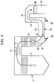
- a solid-gas two-phase stream discharged from a furnace 2 of a coal-fired boiler 1 passes through a flue 10, which is formed, for example, by an iron-sheet duct as shown in Fig. 9 , and is subjected to necessary treatment, such as denitrification, before being released into the atmosphere through a funnel etc. (not shown).
- a first horizontal flue section 11, a first vertical flue section 12, a second horizontal flue section 13, a second vertical flue section 14, a third horizontal flue section 15, and a third vertical flue section 16 are provided sequentially from the upstream side in the flow direction of combustion exhaust gas, i.e., from the side of the furnace 2.
- Reference sign G in the drawings represents the flow of combustion exhaust gas, and 50 represents large-diameter ash.
- a first hopper 20 and a second hopper 30 are installed at the lower ends of the first vertical flue section 12 and the second vertical flue section 14, respectively, to collect large-diameter ash scattered from the furnace 2.
- a denitrification apparatus 40 which denitrifies combustion exhaust gas passing therethrough, is installed in the third vertical flue section 16.
- the first hopper 20 installed at the lower end of the first vertical flue section 12 includes an inclined surface 21 of which the angle is set such that collected large-diameter ash falls.
- the conventional inclined surface 21 has a high coefficient of restitution, so that large-diameter ash rebounding far off the inclined surface 21 has a high probability of jumping over the first hopper 20 and scattering to the second horizontal flue section 13.
- the denitrification apparatus 40 has a configuration in which a denitrification agent (denitrification catalyst) of vanadium dioxide supported on a lattice-shaped titanium oxide carrier is placed in a pallet, and a large number of this pallet are disposed inside the apparatus.
- a denitrification agent denitrification catalyst
- combustion exhaust gas which is a solid-gas two-phase stream, is denitrified while passing through the denitrification apparatus 40, but at the same time the lattice-shaped denitrification catalyst is clogged with large-diameter ash passing therethrough along with the combustion exhaust gas.
- a common practice is to install a metal-mesh trapping screen S inside the flue on the downstream side from the first hopper 20, as shown in PTL 1 and PTL 2, for example.
- the present invention aims to provide a duct wall surface structure which, in a flue of an iron-sheet duct equipped with a hopper through which a solid-gas two-phase stream flows, can enhance the solid particle trapping efficiency of the hopper and thereby reduce the outflow of the solid particles to the downstream side of the duct.
- the present invention has adopted the following solutions.
- a duct wall surface structure of an iron-sheet duct through which a solid-gas two-phase stream containing solid particles flows the duct wall surface structure including a hopper provided at the lower end of the iron-sheet duct which is installed in such a direction that the stream has a vertical component of velocity or in a middle of the duct to collect the solid particles from the stream, wherein a low-rebound structure part having a lower coefficient of restitution than an iron sheet is provided in a region of an inner wall surface of the duct with which the solid particles collide, or provided inside a flow channel of the duct, on the upstream side or the downstream side in the flow direction from the hopper.
- the amount of rebound of solid particles colliding with the low-rebound structure part is reduced, since the low-rebound structure part having a lower coefficient of restitution than an iron sheet is provided in the region of the inner wall surface of the duct with which the solid particles collide, or provided inside the flow channel of the duct, on the upstream side or the downstream side in the flow direction from the hopper.
- the low-rebound structure part is located on the upstream side in the flow direction from the hopper, the amount of solid particles jumping over the hopper and scattering and flowing out to the downstream side is reduced, so that the solid particle trapping efficiency of the hopper is enhanced.
- the low-rebound structure part is located on the downstream side in the flow direction from the hopper, the amount of solid particles reaching the center of the flow channel cross-section or the vicinity thereof, where the flow velocity is higher, and flowing out to the downstream side along with the stream is reduced, so that the solid particle trapping efficiency of the hopper is enhanced as the solid particles having separated from the stream and fallen into the hopper are collected.
- the low-rebound part is a low-rebound part forming member which is installed on the inner wall surface of the iron-sheet duct with a space therebetween and includes openings serving as a passage for the solid particles.
- the solid particles having passed through the openings of the low-rebound part forming member have a high probability of rebounding upon collision with the inner wall surface and then re-colliding with the rear side of the low-rebound part forming member.
- the solid particles fall inside the space along the inner wall surface and are collected in the hopper.
- the trapping efficiency of the hopper is enhanced.
- a preferred low-rebound part forming member is desirably a lattice-shaped member, such as a metal mesh, a grating, or a perforated plate, which has a large number of openings of a size large enough for solid particles to pass through.
- a lattice-shaped member such as a metal mesh, a grating, or a perforated plate, which has a large number of openings of a size large enough for solid particles to pass through.
- an elastically-deformable material such as a metal mesh
- the low-rebound part is a low-rebound part forming member which is installed on the inner wall surface of the iron-sheet duct and elastically deforms upon collision of the solid particles therewith.
- the collision energy of the solid particles is efficiently absorbed through elastic deformation, the amount of rebound of the solid particles colliding with the low-rebound part forming member is reduced, and the trapping efficiency of the hopper is enhanced accordingly.
- a material such as a wire, a metal mesh, or a heat insulation material, which elastically deforms upon collision of solid particles therewith can be used as the low-rebound part forming member.
- the solid-gas two-phase stream is combustion exhaust gas which is discharged from a coal-fired boiler and contains coal ash.
- the trapping efficiency of the hopper is enhanced, as well as the amount of solid particles reaching a denitrification apparatus installed on the downstream side is reduced.
- the solid particle trapping efficiency of the hopper can be enhanced and thereby the outflow of the solid particles to the downstream side of the duct can be reduced.
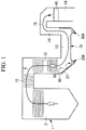
- Fig. 1 illustrates a duct wall surface structure of a flue 10 through which combustion exhaust gas, which is a solid-gas two-phase stream discharged from a furnace 2 of a coal-fired boiler 1, flows before being released into the atmosphere through a funnel etc. (not shown).
- This flue 10 is a combustion exhaust gas flow channel formed by an iron-sheet duct, and typically has a rectangular cross-section.
- the combustion exhaust gas discharged from the furnace 2 is a solid-gas two-phase stream containing fly ash and coal ash (solid particles) called large-diameter ash.
- the combustion exhaust gas is subjected to necessary treatment, such as denitrification, while passing through the flue 10, and then flows as indicated by the arrow G in Fig. 1 before being released into the atmosphere through a funnel etc. (not shown).
- a first horizontal flue section 11, a first vertical flue section 12, a second horizontal flue section 13, a second vertical flue section 14, a third horizontal flue section 15, and a third vertical flue section 16 are provided sequentially from the side of the furnace 2 which is the upstream side in the flow direction of combustion exhaust gas.
- a first hopper 20A is installed at the lower end of the first vertical flue section 12 through which combustion exhaust gas having a downward component of velocity flows
- a second hopper 30A is installed at the lower end of the second vertical flue section 14 through which combustion exhaust gas having an upward component of velocity flows.
- a denitrification apparatus 40 which denitrifies combustion exhaust gas passing therethrough is installed.
- the above-mentioned first hopper 20A and second hopper 30A are installed mainly for the purpose of collecting large-diameter ash contained in combustion exhaust gas. Fly ash of an extremely small particle size is rarely separated from the stream of combustion exhaust gas, and therefore, unlike large-diameter ash, flows through the flue 10 without being collected in the first hopper 20A and the second hopper 30A.
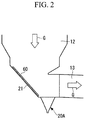
- the first hopper 20A includes an inclined surface 21 on the upstream side of which the angle is set to be an angle of repose or larger so that large-diameter ash falls.
- the inclined surface 21 on the upstream side from the first hopper 20A is designed as a low-rebound part (low-rebound structure part) 60 having a low-rebound structure with a lower coefficient of restitution than that of an iron sheet.
- the inclined surface 21 is at the same time the duct inner wall surface of the flue 10 located in the vicinity of the first hopper 20A on the upstream side (located near the hopper), and if this inclined surface 21 is designed as the low-rebound part 60 having a low-rebound structure, the amount of rebound upon collision with the low-rebound part 60 of the large-diameter ash 50 falling along with a downward stream is suppressed.
- the large-diameter ash 50 falling along with a downward stream (the flow of combustion exhaust gas having a downward component of velocity) rebounds in a smaller amount than when the large-diameter ash 50 collides directly with the conventional inclined surface 21 which is an iron plate.
- the large-diameter ash 50 has a lower probability of jumping over the first hopper 20A and scattering to the second horizontal flue section 13, and the large-diameter ash trapping efficiency of the first hopper 20A is enhanced accordingly.
- Such enhancement in large-diameter ash trapping efficiency leads to a reduction in amount of large-diameter ash 50 scattering and flowing out to the downstream side of the flue 10. Accordingly, the amount of large particle ash (LPA) reaching the denitrification apparatus 40 installed in the third vertical flue section 16 can be reduced.
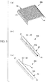
- a low-rebound part 60A of a first specific example shown in Fig. 3 is formed by installing a metal mesh (low-rebound part forming member) 62 on the inclined surface 21, which is the inner wall surface of the iron-sheet duct, with a space 61 provided therebetween.
- This metal mesh 62 is provided with a large number of openings 62a serving as a passage for the large-diameter ash 50.
- the solid particle having passed through the opening 62a of the metal mesh 62 rebounds upon collision with the inclined surface 21 which is the inner wall surface of the iron-sheet duct, but has a high probability of thereafter re-colliding with the rear side of the metal mesh 62.
- the large-diameter ash 50 having collided with the rear side of the metal mesh 62 falls inside the space 61 along the inclined surface 21 and is eventually collected in the first hopper 20A.
- the large-diameter ash 50 passes through the openings 62a of the metal mesh 62, but some collide with the metal mesh 62 which is composed of linear members combined into a lattice shape.
- the large-diameter ash 50 having collided with the linear member of the metal mesh 62 collides with the member which has a lower coefficient of restitution than a common iron sheet and is easily elastically-deformable. As a result, the amount of rebound is reduced and this large-diameter ash 50 has a higher probability of being collected in the first hopper 20A.
- the above-described low-rebound part 60A allows the first hopper 20A to efficiently collect the large-diameter ash 50 having passed through the openings of the metal mesh 62 and the large-diameter ash 50 having collided with the metal mesh 62, and is therefore effective in enhancing the efficiency of trapping the large-diameter ash 50 in the first hopper 20A.
- the metal mesh 62 is used as the low-rebound member in the above first specific example
- members such as a grating, a perforated plate, and a blind structure (shutter), which have a lattice shape having a large number of openings of a size large enough for the large-diameter ash 50 to pass through can be used as the low-rebound member suitable for this specific example.
- a lattice-shaped low-rebound member composed of a material which, like the linear members of the metal mesh 62, elastically deforms upon collision of the large-diameter ash 50 therewith is adopted, it is possible to efficiently absorb the collision energy of the large-diameter ash 50 through elastic deformation and thereby reduce the amount of rebound. The amount of rebound can also be reduced as the colliding large-diameter ash 50 rolls.
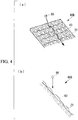
- a low-rebound part 60B of a second specific example shown in Fig. 4 is formed by installing a large number of wires (low-rebound part forming members) 63 with appropriate portions fixed on the wall surface of the inclined surface 21.
- the wire 63 is a material which has lower rigidity than an iron sheet and elastically deforms upon collision of the large-diameter ash 50 therewith. Therefore, the wires 63 are easy to attach/remove or fix when used as a bundle of several wires 63, and it is desirable that the wires 63 are arranged in a lattice shape appropriately combining longitudinal wires and lateral wires as necessary.
- Such wires 63 efficiently absorb the collision energy through elastic deformation upon collision of the large-diameter ash 50 therewith, so that the amount of rebound of the colliding large-diameter ash 50 is reduced and the trapping efficiency of the first hopper 20A is enhanced accordingly. Moreover, the large-diameter ash 50 is likely to roll upon collision with the wires 63, which also contributes to the reduction of velocity energy and the suppression of rebound of the large-diameter ash 50.
- wires 63 are used as the low-rebound member in the above second specific example
- members like a metal mesh which are composed of a material elastically deforming upon collision of the large-diameter ash 50 therewith can be used as the low-rebound member suitable for this specific example.
- a flat-sheet material such as a heat insulation material 64
- a heat insulation material 64 can also be adopted as the low-rebound member and attached to the inclined surface 21.
- a liner of an iron sheet etc. having a high coefficient of restitution is not provided on the surface of the heat insulation material 64 on the inner wall surface side of the flue 10, i.e., on the surface of the heat insulation material with which the large-diameter ash 50 collides.
- heat insulation material 64 for example, a rubber material or a plastic material having a lower coefficient of restitution than an iron sheet can be used as the flat-sheet low-rebound part 60C.
- low-rebound parts (low-rebound structure parts) 70, 80 having a low-rebound structure shown in Fig. 6 are provided in a region of the inner wall surface with which the large-diameter ash 50 collides, or provided inside the flow channel, on the downstream side from the second hopper 30A. That is, the second hopper 30A is installed at the lower end of the second vertical flue section 14 through which an upward stream flows (the flow of combustion exhaust gas having an upward component of velocity), and the low-rebound structure parts 70, 80 having a lower coefficient of restitution than an iron sheet are provided on the downstream side from the second hopper 30A.
- the low-rebound structure part 70 shown in Fig. 6 is provided inside the flow channel of the flue 10 on the downstream side from the second hopper 30A, specifically, inside the flue flow channel at the joint between the second horizontal flue section 13 and the second vertical flue section 14 where the flow direction of the stream is changed from the horizontal direction to the upward direction.
- the low-rebound structure part 70 is provided inside the flue flow channel, above the second hopper 30A.
- this low-rebound structure part 70 has a blind structure composed of a plurality of faces facing a horizontal stream. As the large-diameter ash 50 colliding with the faces of the blind structure slows down and falls into the second hopper 30A, the trapping efficiency of the second hopper 30A is enhanced.
- the low-rebound part 80 shown in Fig. 6 is provided in a region of the inner wall surface with which the large-diameter ash 50 collides on the downstream side from the second hopper 30A, specifically, provided on the wall surface of the second vertical flue section 14 with which a horizontal stream flowing through the second horizontal flue section 13 collides.
- a metal mesh, a bundle of wires, a grating, etc. can be used as this low-rebound part 80.
- the low-rebound part 80 is provided on the downstream side in the flow direction from the second hopper 30A, as the amount of rebound of the large-diameter ash 50 colliding with the low-rebound part 80 is reduced, the amount of large-diameter ash 50 reaching the center of the flow channel cross-section and the vicinity thereof, where the flow velocity is higher, and flowing out to the downstream side along with the stream is reduced.
- the amount of large-diameter ash 50 separating from the stream and falling increases, and therefore collecting this large-diameter ash 50 in the second hopper 30A can enhance the trapping efficiency of the large-diameter ash 50 in the second hopper 30A.
- the configurations of the first to third specific examples described above can be adopted for the low-rebound part 80.
- a configuration in which the low-rebound part 80 is appropriately combined with the low-rebound part 70 can also be adopted depending on the conditions.
- examples of materials having a lower coefficient of restitution than an iron sheet include, other than rubber materials and plastic materials, stainless steel, copper, aluminum, phosphor bronze, monel, highly corrosion-resistant alloys (HC-22, HC-276), nickel-based superalloys (Inconel 600(R), Inconel 601(R)), nickel, and nickel 201. These materials can be appropriately selected and used in the form of a sheet, a metal mesh, wires, etc. as described above.
- Fig. 7 shows results of a trial calculation in which the relation between the particle size (mm), which is the diameter of solid particles, and the scatter reduction rate (%) for the above-described low-rebound structure was numerically simulated. Specifically, Fig. 7 shows a trial calculation for verifying the effectiveness of the low-rebound structure, in which the above-described low-rebound structure is more effective for a particle size for which the scatter reduction rate is higher.
- the trial calculation of the relation shown in Fig. 7 involves two types of low-rebound structures (low-rebound member a, low-rebound member b).
- the scatter reduction rate starts to increase when the particle size (d) is about 0.3 mm, and the scatter reduction rate reaches 100% when the particle size (d) is as large as about 5 mm.
- the low-rebound structure of the above embodiment is effective when the particle size (d) of the solid particles is within the range of 0.3 mm or more to 5 mm or less.
- the flues (iron-sheet duct structures) shown in Fig. 8 are other configuration examples to which the duct wall surface structure of the above embodiment is applicable.
- the flue 10 shown in Fig. 8(a) is an example of the flue composed of a horizontal flue section and a vertical flue section through which a stream flows upward.
- the first hopper 20A and the second hopper 30A are installed at the lower ends of the first vertical flue section 12 and the second vertical flue section 14, respectively, which are connected at both ends of the second horizontal flue section 13.
- a flue 10A shown in Fig. 8(b) is an example of the flue composed of the first vertical flue 12 and a horizontal flue section 15A, with an inclined flue 17, in which a stream has an upward component of velocity, connecting therebetween.
- the first hopper 20A is installed at the lower end of the first vertical flue section 12, and a second hopper 30B is installed in the middle of the inclined flue 17.
- providing a low-rebound structure in the form of a blind, for example, inside the flow channel on the downstream side from the second hopper 30B can enhance the trapping efficiency.
- a flue 10B shown in Fig. 8(c) is an example of the flue composed of a horizontal flue section and a vertical flue section through which a stream flows downward.
- the flue 10B includes, instead of the second vertical flue section 14 shown in Fig. 8(a) , a second vertical flue section 14A which is provided downward from the end of the second horizontal flue section 13.
- a stream flows downward in the vertical direction on the downstream side from a second hopper 30C, providing a low-rebound structure in the form of a blind, for example, inside the flow channel on the upstream side or the downstream side from the second hopper 30C can enhance the trapping efficiency.
- the large-diameter particle trapping efficiency of the hopper provided in the middle of the duct can be enhanced, and therefore the outflow of the solid particles to the downstream side of the duct can be reduced.
- the solid-gas two-phase stream containing solid particles is assumed to be coal-ash discharged from the furnace 2 of the coal-fired boiler 1.
- the iron-sheet duct employing the duct wall surface structure of the embodiment is also applicable to apparatuses through which flow various streams containing, for example, soot, iron powder, diesel exhaust particles, and unburned particles, as solid particles.
Landscapes
- Engineering & Computer Science (AREA)
- Chemical & Material Sciences (AREA)
- Mechanical Engineering (AREA)
- General Engineering & Computer Science (AREA)
- Combustion & Propulsion (AREA)
- Chemical Kinetics & Catalysis (AREA)
- Incineration Of Waste (AREA)
Abstract
Description
- The present invention relates to a duct wall surface structure of an iron-sheet duct through which a solid-gas two-phase stream containing solid particles flows, such as combustion exhaust gas discharged from a coal-fired boiler.
- Conventionally, a coal-fired boiler discharges combustion exhaust gas, produced by coal combustion, from a furnace. This combustion exhaust gas contains fly ash and coal ash (solid particles) called high-porosity large-diameter ash (hereinafter referred to as "large-diameter ash"), with the details varying depending on the type of coal.
- Of these ashes, fly ash is extremely fine particles with a particle size in the order of several micrometers. By comparison, large-diameter ash is relatively large particles with a particle size of about 1 mm or more, but has a low apparent specific gravity due to its high porosity.
- A solid-gas two-phase stream discharged from a
furnace 2 of a coal-firedboiler 1 passes through aflue 10, which is formed, for example, by an iron-sheet duct as shown inFig. 9 , and is subjected to necessary treatment, such as denitrification, before being released into the atmosphere through a funnel etc. (not shown). - In the
flue 10 shown inFig. 9 , a firsthorizontal flue section 11, a firstvertical flue section 12, a secondhorizontal flue section 13, a secondvertical flue section 14, a thirdhorizontal flue section 15, and a thirdvertical flue section 16 are provided sequentially from the upstream side in the flow direction of combustion exhaust gas, i.e., from the side of thefurnace 2. Reference sign G in the drawings represents the flow of combustion exhaust gas, and 50 represents large-diameter ash. - In the configuration example shown in
Fig. 9 , afirst hopper 20 and asecond hopper 30 are installed at the lower ends of the firstvertical flue section 12 and the secondvertical flue section 14, respectively, to collect large-diameter ash scattered from thefurnace 2. In addition, adenitrification apparatus 40, which denitrifies combustion exhaust gas passing therethrough, is installed in the thirdvertical flue section 16. Thefirst hopper 20 installed at the lower end of the firstvertical flue section 12 includes aninclined surface 21 of which the angle is set such that collected large-diameter ash falls. However, being an iron-sheet wall surface as with the duct, the conventionalinclined surface 21 has a high coefficient of restitution, so that large-diameter ash rebounding far off theinclined surface 21 has a high probability of jumping over thefirst hopper 20 and scattering to the secondhorizontal flue section 13. - In particular, since the flow velocity of combustion exhaust gas is higher at the center of the cross-section of the
flue 10, large-diameter ash having jumped over thefirst hopper 20 and joined the fast stream of combustion exhaust gas is highly likely to reach thedenitrification apparatus 40 without being collected in thesecond hopper 30, either, due to its low apparent specific gravity. - For example, the
denitrification apparatus 40 has a configuration in which a denitrification agent (denitrification catalyst) of vanadium dioxide supported on a lattice-shaped titanium oxide carrier is placed in a pallet, and a large number of this pallet are disposed inside the apparatus. Thus, combustion exhaust gas, which is a solid-gas two-phase stream, is denitrified while passing through thedenitrification apparatus 40, but at the same time the lattice-shaped denitrification catalyst is clogged with large-diameter ash passing therethrough along with the combustion exhaust gas. - To prevent such clogging of a denitrification catalyst, a common practice is to install a metal-mesh trapping screen S inside the flue on the downstream side from the
first hopper 20, as shown inPTL 1 andPTL 2, for example. -
- {PTL 1}
U.S. Patent No. 6994036 - {PTL 2}
Japanese Unexamined Patent Application, Publication No.Hei 2-95415 - {PTL 3}
Japanese Unexamined Patent Application, Publication No.2008-241061 - As the trapping screen S installed inside the flue on the downstream side from the
first hopper 20 wears or clogs itself, replacement etc. of the screen is required, which pushes up the operation cost. Moreover, if the trapping screen S is clogged, the effective flow channel cross-sectional area of theflue 10 is reduced, which may lead to larger pressure loss. - In view of these circumstances, it is desirable, in the duct wall surface structure of a flue through which a solid-gas two-phase stream flows such as combustion exhaust gas discharged from a coal-fired boiler, to enhance the efficiency of trapping solid particles like large-diameter ash in the hopper and thereby reduce the outflow of the solid particles to the downstream side of the flue.
- Having been devised to solve the above problems, the present invention aims to provide a duct wall surface structure which, in a flue of an iron-sheet duct equipped with a hopper through which a solid-gas two-phase stream flows, can enhance the solid particle trapping efficiency of the hopper and thereby reduce the outflow of the solid particles to the downstream side of the duct.
- To solve the above problems, the present invention has adopted the following solutions.
- According to one aspect of the present invention, there is provided a duct wall surface structure of an iron-sheet duct through which a solid-gas two-phase stream containing solid particles flows, the duct wall surface structure including a hopper provided at the lower end of the iron-sheet duct which is installed in such a direction that the stream has a vertical component of velocity or in a middle of the duct to collect the solid particles from the stream, wherein a low-rebound structure part having a lower coefficient of restitution than an iron sheet is provided in a region of an inner wall surface of the duct with which the solid particles collide, or provided inside a flow channel of the duct, on the upstream side or the downstream side in the flow direction from the hopper.
- According to such a duct wall surface structure, the amount of rebound of solid particles colliding with the low-rebound structure part is reduced, since the low-rebound structure part having a lower coefficient of restitution than an iron sheet is provided in the region of the inner wall surface of the duct with which the solid particles collide, or provided inside the flow channel of the duct, on the upstream side or the downstream side in the flow direction from the hopper.
- As a result, if the low-rebound structure part is located on the upstream side in the flow direction from the hopper, the amount of solid particles jumping over the hopper and scattering and flowing out to the downstream side is reduced, so that the solid particle trapping efficiency of the hopper is enhanced. On the other hand, if the low-rebound structure part is located on the downstream side in the flow direction from the hopper, the amount of solid particles reaching the center of the flow channel cross-section or the vicinity thereof, where the flow velocity is higher, and flowing out to the downstream side along with the stream is reduced, so that the solid particle trapping efficiency of the hopper is enhanced as the solid particles having separated from the stream and fallen into the hopper are collected.
- In the above aspect, it is preferable that the low-rebound part is a low-rebound part forming member which is installed on the inner wall surface of the iron-sheet duct with a space therebetween and includes openings serving as a passage for the solid particles. In this case, the solid particles having passed through the openings of the low-rebound part forming member have a high probability of rebounding upon collision with the inner wall surface and then re-colliding with the rear side of the low-rebound part forming member. Thus, the solid particles fall inside the space along the inner wall surface and are collected in the hopper. Moreover, as the amount of rebound of the solid particles colliding with the low-rebound part forming member having a lower coefficient of restitution than an iron sheet is reduced, the trapping efficiency of the hopper is enhanced.
- A preferred low-rebound part forming member is desirably a lattice-shaped member, such as a metal mesh, a grating, or a perforated plate, which has a large number of openings of a size large enough for solid particles to pass through. In particular, if an elastically-deformable material, such as a metal mesh, is adopted, the collision energy of solid particles can be efficiently absorbed through elastic deformation.
- In the above aspect, it is preferable that the low-rebound part is a low-rebound part forming member which is installed on the inner wall surface of the iron-sheet duct and elastically deforms upon collision of the solid particles therewith. Thus, since the collision energy of the solid particles is efficiently absorbed through elastic deformation, the amount of rebound of the solid particles colliding with the low-rebound part forming member is reduced, and the trapping efficiency of the hopper is enhanced accordingly.
- A material, such as a wire, a metal mesh, or a heat insulation material, which elastically deforms upon collision of solid particles therewith can be used as the low-rebound part forming member.
- In the above aspect, the solid-gas two-phase stream is combustion exhaust gas which is discharged from a coal-fired boiler and contains coal ash. In this case, as the amount of rebound of large-diameter ash of the coal ash colliding with the low-rebound part is reduced, the trapping efficiency of the hopper is enhanced, as well as the amount of solid particles reaching a denitrification apparatus installed on the downstream side is reduced.
- According to the above-described present invention, in an iron-sheet duct (flue) equipped with a hopper through which a solid-gas two-phase stream flows, the solid particle trapping efficiency of the hopper can be enhanced and thereby the outflow of the solid particles to the downstream side of the duct can be reduced.
-
- {
Fig. 1 }
Fig. 1 is a longitudinal cross-sectional view showing a flue of a coal-fired boiler as one embodiment of a duct wall surface structure according to the present invention. - {
Fig. 2 }
Fig. 2 is an enlarged longitudinal cross-sectional view showing the structure around a first hopper in the duct wall surface structure shown inFig. 1 . - {
Fig. 3 }
Fig. 3 is a view showing a first specific example of a low-rebound structure part shown inFig. 2 , in whichFig. 3(a) is a perspective view showing the outline of a low-rebound structure part formed by installing a member having a large number of openings on a wall surface with a space provided therebetween;Fig. 3(b) is a cross-sectional view showing the movement of a solid particle having passed through the opening; andFig. 3(c) is a cross-sectional view showing the movement of a solid particle which has failed to pass through the opening. - {
Fig. 4 }
Fig. 4 is a view showing a second specific example of the low-rebound structure part shown inFig. 2 , in whichFig. 4(a) is a perspective view showing the outline of a low-rebound structure part formed by installing a low-rebound member, such as wires, on the wall surface, andFig. 4(b) is a cross-sectional view ofFig. 4(a) . - {
Fig. 5 }
Fig. 5 is a view showing a third specific example of the low-rebound structure part shown inFig. 2 , and is a cross-sectional view of a low-rebound structure part formed by installing a low-rebound member in a substantially planar shape on the wall surface. - {
Fig. 6 }
Fig. 6 is an enlarged longitudinal cross-sectional view showing the structure around a second hopper in the duct wall surface structure shown inFig. 1 . - {
Fig. 7 }
Fig. 7 is a view showing the relation between the particle size of solid particles and a scatter reduction rate for two types of low-rebound members. - {
Fig. 8 }
Fig. 8 is a view showing other examples of the flue to which the duct wall surface structure of the present invention is applicable, in whichFig. 8(a) is an example of the flue composed of a horizontal flue section and a vertical flue section through which a stream flows upward;Fig. 8(b) is an example of the flue composed of an inclined flue; andFig. 8(c) is an example of the flue composed of a horizontal flue section and a vertical flue section through which a stream flows downward. - {
Fig. 9 }
Fig. 9 is a longitudinal cross-sectional view showing a flue of a coal-fired boiler as an example of a conventional duct wall surface structure. - In the following, one embodiment of a duct wall surface structure according to the present invention will be described on the basis of the drawings.
-
Fig. 1 illustrates a duct wall surface structure of aflue 10 through which combustion exhaust gas, which is a solid-gas two-phase stream discharged from afurnace 2 of a coal-firedboiler 1, flows before being released into the atmosphere through a funnel etc. (not shown). Thisflue 10 is a combustion exhaust gas flow channel formed by an iron-sheet duct, and typically has a rectangular cross-section. The combustion exhaust gas discharged from thefurnace 2 is a solid-gas two-phase stream containing fly ash and coal ash (solid particles) called large-diameter ash. The combustion exhaust gas is subjected to necessary treatment, such as denitrification, while passing through theflue 10, and then flows as indicated by the arrow G inFig. 1 before being released into the atmosphere through a funnel etc. (not shown). - In the
flue 10 shown inFig. 1 , a firsthorizontal flue section 11, a firstvertical flue section 12, a secondhorizontal flue section 13, a secondvertical flue section 14, a thirdhorizontal flue section 15, and a thirdvertical flue section 16 are provided sequentially from the side of thefurnace 2 which is the upstream side in the flow direction of combustion exhaust gas. - In the
flue 10 shown inFig. 1 , afirst hopper 20A is installed at the lower end of the firstvertical flue section 12 through which combustion exhaust gas having a downward component of velocity flows, and asecond hopper 30A is installed at the lower end of the secondvertical flue section 14 through which combustion exhaust gas having an upward component of velocity flows. In the thirdvertical flue section 16 through which combustion exhaust gas flows downward, adenitrification apparatus 40 which denitrifies combustion exhaust gas passing therethrough is installed. - The above-mentioned
first hopper 20A andsecond hopper 30A are installed mainly for the purpose of collecting large-diameter ash contained in combustion exhaust gas. Fly ash of an extremely small particle size is rarely separated from the stream of combustion exhaust gas, and therefore, unlike large-diameter ash, flows through theflue 10 without being collected in thefirst hopper 20A and thesecond hopper 30A. - As shown in
Fig. 1 andFig. 2 , thefirst hopper 20A includes aninclined surface 21 on the upstream side of which the angle is set to be an angle of repose or larger so that large-diameter ash falls. In this embodiment, to effectively enhance the trapping efficiency of thefirst hopper 20A, theinclined surface 21 on the upstream side from thefirst hopper 20A is designed as a low-rebound part (low-rebound structure part) 60 having a low-rebound structure with a lower coefficient of restitution than that of an iron sheet. - That is, the
inclined surface 21 is at the same time the duct inner wall surface of theflue 10 located in the vicinity of thefirst hopper 20A on the upstream side (located near the hopper), and if thisinclined surface 21 is designed as the low-rebound part 60 having a low-rebound structure, the amount of rebound upon collision with the low-rebound part 60 of the large-diameter ash 50 falling along with a downward stream is suppressed. - As a result, the large-
diameter ash 50 falling along with a downward stream (the flow of combustion exhaust gas having a downward component of velocity) rebounds in a smaller amount than when the large-diameter ash 50 collides directly with the conventionalinclined surface 21 which is an iron plate. Thus, the large-diameter ash 50 has a lower probability of jumping over thefirst hopper 20A and scattering to the secondhorizontal flue section 13, and the large-diameter ash trapping efficiency of thefirst hopper 20A is enhanced accordingly. Such enhancement in large-diameter ash trapping efficiency leads to a reduction in amount of large-diameter ash 50 scattering and flowing out to the downstream side of theflue 10. Accordingly, the amount of large particle ash (LPA) reaching thedenitrification apparatus 40 installed in the thirdvertical flue section 16 can be reduced. - Here, specific configuration examples of the above-described low-
rebound part 60 will be described on the basis of the drawings. - A low-
rebound part 60A of a first specific example shown inFig. 3 is formed by installing a metal mesh (low-rebound part forming member) 62 on theinclined surface 21, which is the inner wall surface of the iron-sheet duct, with aspace 61 provided therebetween. Thismetal mesh 62 is provided with a large number ofopenings 62a serving as a passage for the large-diameter ash 50. - If such a low-
rebound part 60A is adopted, as shown inFig. 3(b) , the solid particle having passed through theopening 62a of themetal mesh 62 rebounds upon collision with theinclined surface 21 which is the inner wall surface of the iron-sheet duct, but has a high probability of thereafter re-colliding with the rear side of themetal mesh 62. Thus, the large-diameter ash 50 having collided with the rear side of themetal mesh 62 falls inside thespace 61 along theinclined surface 21 and is eventually collected in thefirst hopper 20A. - However, not all of the large-
diameter ash 50 passes through theopenings 62a of themetal mesh 62, but some collide with themetal mesh 62 which is composed of linear members combined into a lattice shape. As shown inFig. 3(c) , the large-diameter ash 50 having collided with the linear member of themetal mesh 62 collides with the member which has a lower coefficient of restitution than a common iron sheet and is easily elastically-deformable. As a result, the amount of rebound is reduced and this large-diameter ash 50 has a higher probability of being collected in thefirst hopper 20A. - Thus, the above-described low-
rebound part 60A allows thefirst hopper 20A to efficiently collect the large-diameter ash 50 having passed through the openings of themetal mesh 62 and the large-diameter ash 50 having collided with themetal mesh 62, and is therefore effective in enhancing the efficiency of trapping the large-diameter ash 50 in thefirst hopper 20A. - While the
metal mesh 62 is used as the low-rebound member in the above first specific example, other than themetal mesh 62, members, such as a grating, a perforated plate, and a blind structure (shutter), which have a lattice shape having a large number of openings of a size large enough for the large-diameter ash 50 to pass through can be used as the low-rebound member suitable for this specific example. - In particular, if a lattice-shaped low-rebound member composed of a material which, like the linear members of the
metal mesh 62, elastically deforms upon collision of the large-diameter ash 50 therewith is adopted, it is possible to efficiently absorb the collision energy of the large-diameter ash 50 through elastic deformation and thereby reduce the amount of rebound. The amount of rebound can also be reduced as the colliding large-diameter ash 50 rolls. - A low-
rebound part 60B of a second specific example shown inFig. 4 is formed by installing a large number of wires (low-rebound part forming members) 63 with appropriate portions fixed on the wall surface of theinclined surface 21. Thewire 63 is a material which has lower rigidity than an iron sheet and elastically deforms upon collision of the large-diameter ash 50 therewith. Therefore, thewires 63 are easy to attach/remove or fix when used as a bundle ofseveral wires 63, and it is desirable that thewires 63 are arranged in a lattice shape appropriately combining longitudinal wires and lateral wires as necessary. -
Such wires 63 efficiently absorb the collision energy through elastic deformation upon collision of the large-diameter ash 50 therewith, so that the amount of rebound of the colliding large-diameter ash 50 is reduced and the trapping efficiency of thefirst hopper 20A is enhanced accordingly. Moreover, the large-diameter ash 50 is likely to roll upon collision with thewires 63, which also contributes to the reduction of velocity energy and the suppression of rebound of the large-diameter ash 50. - While the
wires 63 are used as the low-rebound member in the above second specific example, other than thewires 63, members like a metal mesh which are composed of a material elastically deforming upon collision of the large-diameter ash 50 therewith can be used as the low-rebound member suitable for this specific example. - Like a low-
rebound part 60C shown inFig. 5 as a third specific example, a flat-sheet material, such as aheat insulation material 64, can also be adopted as the low-rebound member and attached to theinclined surface 21. When theheat insulation material 64 is adopted, a liner of an iron sheet etc. having a high coefficient of restitution is not provided on the surface of theheat insulation material 64 on the inner wall surface side of theflue 10, i.e., on the surface of the heat insulation material with which the large-diameter ash 50 collides. - Since such a
heat insulation material 64 elastically deforms upon collision of the large-diameter ash 50 therewith and efficiently absorbs the collision energy, the amount of rebound of the colliding large-diameter ash 50 is reduced and the trapping efficiency of thefirst hopper 20A is enhanced accordingly. - Other than the
heat insulation material 64, for example, a rubber material or a plastic material having a lower coefficient of restitution than an iron sheet can be used as the flat-sheet low-rebound part 60C. - Next, low-rebound parts (low-rebound structure parts) 70, 80 having a low-rebound structure shown in
Fig. 6 are provided in a region of the inner wall surface with which the large-diameter ash 50 collides, or provided inside the flow channel, on the downstream side from thesecond hopper 30A. That is, thesecond hopper 30A is installed at the lower end of the secondvertical flue section 14 through which an upward stream flows (the flow of combustion exhaust gas having an upward component of velocity), and the low-rebound structure parts second hopper 30A. - The low-
rebound structure part 70 shown inFig. 6 is provided inside the flow channel of theflue 10 on the downstream side from thesecond hopper 30A, specifically, inside the flue flow channel at the joint between the secondhorizontal flue section 13 and the secondvertical flue section 14 where the flow direction of the stream is changed from the horizontal direction to the upward direction. In other words, the low-rebound structure part 70 is provided inside the flue flow channel, above thesecond hopper 30A. For example, this low-rebound structure part 70 has a blind structure composed of a plurality of faces facing a horizontal stream. As the large-diameter ash 50 colliding with the faces of the blind structure slows down and falls into thesecond hopper 30A, the trapping efficiency of thesecond hopper 30A is enhanced. - The low-
rebound part 80 shown inFig. 6 is provided in a region of the inner wall surface with which the large-diameter ash 50 collides on the downstream side from thesecond hopper 30A, specifically, provided on the wall surface of the secondvertical flue section 14 with which a horizontal stream flowing through the secondhorizontal flue section 13 collides. For example, a metal mesh, a bundle of wires, a grating, etc. can be used as this low-rebound part 80. - If such a low-
rebound part 80 is provided, most of the large-diameter ash 50, which has joined a stream flowing in the horizontal direction through the secondhorizontal flue section 13, collides under inertial force with the low-rebound part 80 provided in the region of the inner wall surface at the far end of the secondhorizontal flue section 13. The large-diameter ash 50 rebounding upon this collision heads for the center in the flow channel cross-section of the secondvertical flow channel 14, but, due to the lower coefficient of restitution than that of a conventional iron sheet, the large-diameter ash 50 reaches the center of the flow channel cross-section and the vicinity thereof, where the flow velocity is higher, at a lower rate. - That is, if the low-
rebound part 80 is provided on the downstream side in the flow direction from thesecond hopper 30A, as the amount of rebound of the large-diameter ash 50 colliding with the low-rebound part 80 is reduced, the amount of large-diameter ash 50 reaching the center of the flow channel cross-section and the vicinity thereof, where the flow velocity is higher, and flowing out to the downstream side along with the stream is reduced. As a result, the amount of large-diameter ash 50 separating from the stream and falling increases, and therefore collecting this large-diameter ash 50 in thesecond hopper 30A can enhance the trapping efficiency of the large-diameter ash 50 in thesecond hopper 30A. - In this case, the configurations of the first to third specific examples described above can be adopted for the low-
rebound part 80. Alternatively, a configuration in which the low-rebound part 80 is appropriately combined with the low-rebound part 70 can also be adopted depending on the conditions. - Here, examples of materials having a lower coefficient of restitution than an iron sheet include, other than rubber materials and plastic materials, stainless steel, copper, aluminum, phosphor bronze, monel, highly corrosion-resistant alloys (HC-22, HC-276), nickel-based superalloys (Inconel 600(R), Inconel 601(R)), nickel, and nickel 201. These materials can be appropriately selected and used in the form of a sheet, a metal mesh, wires, etc. as described above.
-
Fig. 7 shows results of a trial calculation in which the relation between the particle size (mm), which is the diameter of solid particles, and the scatter reduction rate (%) for the above-described low-rebound structure was numerically simulated. Specifically,Fig. 7 shows a trial calculation for verifying the effectiveness of the low-rebound structure, in which the above-described low-rebound structure is more effective for a particle size for which the scatter reduction rate is higher. The trial calculation of the relation shown inFig. 7 involves two types of low-rebound structures (low-rebound member a, low-rebound member b). The scatter reduction rate starts to increase when the particle size (d) is about 0.3 mm, and the scatter reduction rate reaches 100% when the particle size (d) is as large as about 5 mm. Thus, the low-rebound structure of the above embodiment is effective when the particle size (d) of the solid particles is within the range of 0.3 mm or more to 5 mm or less. - The flues (iron-sheet duct structures) shown in
Fig. 8 are other configuration examples to which the duct wall surface structure of the above embodiment is applicable. - As with the embodiment shown in
Fig. 1 , theflue 10 shown inFig. 8(a) is an example of the flue composed of a horizontal flue section and a vertical flue section through which a stream flows upward. In this example of the flue, thefirst hopper 20A and thesecond hopper 30A are installed at the lower ends of the firstvertical flue section 12 and the secondvertical flue section 14, respectively, which are connected at both ends of the secondhorizontal flue section 13. - A
flue 10A shown inFig. 8(b) is an example of the flue composed of the firstvertical flue 12 and ahorizontal flue section 15A, with aninclined flue 17, in which a stream has an upward component of velocity, connecting therebetween. In this example of the flue, thefirst hopper 20A is installed at the lower end of the firstvertical flue section 12, and asecond hopper 30B is installed in the middle of theinclined flue 17. - In this example of the flue, providing a low-rebound structure in the form of a blind, for example, inside the flow channel on the downstream side from the
second hopper 30B can enhance the trapping efficiency. - A
flue 10B shown inFig. 8(c) is an example of the flue composed of a horizontal flue section and a vertical flue section through which a stream flows downward. Specifically, theflue 10B includes, instead of the secondvertical flue section 14 shown inFig. 8(a) , a secondvertical flue section 14A which is provided downward from the end of the secondhorizontal flue section 13. In this example of the flue, since a stream flows downward in the vertical direction on the downstream side from asecond hopper 30C, providing a low-rebound structure in the form of a blind, for example, inside the flow channel on the upstream side or the downstream side from thesecond hopper 30C can enhance the trapping efficiency. - Thus, according to the above embodiment, in an iron-sheet duct (flue) through which combustion exhaust gas flows (solid-gas two-phase stream) discharged from the coal-fired
boiler 1 and containing coal ash, the large-diameter particle trapping efficiency of the hopper provided in the middle of the duct can be enhanced, and therefore the outflow of the solid particles to the downstream side of the duct can be reduced. As a result, it is possible, for example, to reduce the large-diameter ash reaching thedenitrification apparatus 40, and to thereby suppress or prevent the clogging of the denitrification catalyst. - In the above embodiment, the solid-gas two-phase stream containing solid particles is assumed to be coal-ash discharged from the
furnace 2 of the coal-firedboiler 1. However, the iron-sheet duct employing the duct wall surface structure of the embodiment is also applicable to apparatuses through which flow various streams containing, for example, soot, iron powder, diesel exhaust particles, and unburned particles, as solid particles. - The present invention is not limited to the above-described embodiment but can be appropriately modified within the scope of the present invention.
-
- 1 Coal-fired boiler
- 2 Furnace
- 10, 10A, 10B Flue
- 20, 20A First hopper
- 21 Inclined surface
- 30, 30A to 30C Second hopper
- 40 Denitrification apparatus
- 50 High-porosity large-diameter ash (large-diameter ash)
- 60, 60A to 60C, 70, 80 Low-rebound part (low-rebound structure part)
Claims (4)
- A duct wall surface structure of an iron-sheet duct through which a solid-gas two-phase stream containing solid particles flows, the duct wall surface structure comprising
a hopper provided at a lower end of the iron-sheet duct which is installed in such a direction that the stream has a vertical component of velocity or in a middle of the duct to collect the solid particles from the stream,
wherein a low-rebound structure part having a lower coefficient of restitution than an iron sheet is provided in a region of an inner wall surface of the duct with which the solid particles collide, or provided inside a flow channel of the duct, on an upstream side or a downstream side in a flow direction from the hopper. - The duct wall surface structure according to claim 1, wherein the low-rebound part is a low-rebound part forming member which is installed on an inner wall surface of the iron-sheet duct with a space therebetween and includes openings serving as a passage for the solid particles.
- The duct wall surface structure according to claim 1, wherein the low-rebound part is a low-rebound part forming member which is installed on an inner wall surface of the iron-sheet duct and elastically deforms upon collision of the solid particles therewith.
- The duct wall surface structure according to any one of claims 1 to 3, wherein the solid-gas two-phase stream is combustion exhaust gas which is discharged from a coal-fired boiler and contains coal ash.
Priority Applications (1)
| Application Number | Priority Date | Filing Date | Title |
|---|---|---|---|
| PL14841726T PL3034943T3 (en) | 2013-09-04 | 2014-07-18 | Duct wall surface structure |
Applications Claiming Priority (2)
| Application Number | Priority Date | Filing Date | Title |
|---|---|---|---|
| JP2013183297A JP6005015B2 (en) | 2013-09-04 | 2013-09-04 | Duct wall structure |
| PCT/JP2014/069134 WO2015033679A1 (en) | 2013-09-04 | 2014-07-18 | Duct wall surface structure |
Publications (3)
| Publication Number | Publication Date |
|---|---|
| EP3034943A1 true EP3034943A1 (en) | 2016-06-22 |
| EP3034943A4 EP3034943A4 (en) | 2016-10-19 |
| EP3034943B1 EP3034943B1 (en) | 2018-05-02 |
Family
ID=52628165
Family Applications (1)
| Application Number | Title | Priority Date | Filing Date |
|---|---|---|---|
| EP14841726.4A Not-in-force EP3034943B1 (en) | 2013-09-04 | 2014-07-18 | Duct wall surface structure |
Country Status (8)
| Country | Link |
|---|---|
| US (1) | US10488040B2 (en) |
| EP (1) | EP3034943B1 (en) |
| JP (1) | JP6005015B2 (en) |
| CN (1) | CN105492826B (en) |
| ES (1) | ES2675295T3 (en) |
| PL (1) | PL3034943T3 (en) |
| TW (1) | TWI541474B (en) |
| WO (1) | WO2015033679A1 (en) |
Cited By (1)
| Publication number | Priority date | Publication date | Assignee | Title |
|---|---|---|---|---|
| EP3217096A4 (en) * | 2014-12-12 | 2017-11-15 | Mitsubishi Hitachi Power Systems, Ltd. | Exhaust duct and boiler |
Families Citing this family (8)
| Publication number | Priority date | Publication date | Assignee | Title |
|---|---|---|---|---|
| JP6785046B2 (en) * | 2016-02-26 | 2020-11-18 | 三菱パワー株式会社 | How to remove exhaust ducts, boilers and solid particles |
| JP6727960B2 (en) * | 2016-07-06 | 2020-07-22 | 三菱日立パワーシステムズ株式会社 | Duct structure, boiler and method for removing solid particles from gas-solid two-phase flow |
| CN107376566A (en) * | 2017-08-14 | 2017-11-24 | 张家港市益成机械有限公司 | A kind of tail gas gathering device of immersion paint drying machine |
| US10926968B2 (en) * | 2018-04-13 | 2021-02-23 | BGRS, Inc. | System for removing and collecting dust particles |
| CN109806671B (en) * | 2019-03-21 | 2021-04-06 | 中国航发湖南动力机械研究所 | Particle separator |
| US12427443B2 (en) * | 2021-01-21 | 2025-09-30 | Aisin Corporation | Gas-liquid separator |
| CN113108304B (en) * | 2021-05-28 | 2023-03-21 | 中国化学赛鼎宁波工程有限公司 | Flue gas outlet device of air preheater and flue gas discharge method |
| US11828230B2 (en) * | 2021-10-04 | 2023-11-28 | General Electric Company | System and method for mitigating particulate intrusion to an air intake system of a gas turbine system with intrusion protective coatings tailored to locale of operation |
Family Cites Families (23)
| Publication number | Priority date | Publication date | Assignee | Title |
|---|---|---|---|---|
| US2749905A (en) * | 1956-06-12 | Fireplace hot air furnace | ||
| US4504291A (en) | 1983-06-29 | 1985-03-12 | Mobil Oil Corporation | Dropout boot for power recovery train |
| CH665467A5 (en) | 1984-05-18 | 1988-05-13 | Von Roll Ag | DEVICE FOR DIVERSING FLUE GAS AND FLUE ASH SEPARATION IN A MULTI-TRAIN BOILER. |
| JP2583543B2 (en) | 1987-12-24 | 1997-02-19 | 日本板硝子株式会社 | Heat treatment method for ZnSe or ZnS compound crystal |
| JPH01169933U (en) * | 1988-05-02 | 1989-11-30 | ||
| JP2724176B2 (en) | 1988-09-30 | 1998-03-09 | バブコツク日立株式会社 | Exhaust gas denitration equipment |
| DE19521321A1 (en) * | 1995-06-12 | 1996-12-19 | Abb Management Ag | Method and device for reducing the dust content of the exhaust gases of a steam generator |
| JPH10165734A (en) * | 1996-12-16 | 1998-06-23 | Hitachi Ltd | Ash particle collection device |
| CN2322048Y (en) | 1997-03-14 | 1999-06-02 | 大连科达环保设备厂 | Dust-removing desulfurizer |
| EP0903536A1 (en) * | 1997-09-23 | 1999-03-24 | Asea Brown Boveri AG | Steam generator with integrated dust separator |
| DE10227639B4 (en) | 2002-06-20 | 2006-06-22 | Steag Encotec Gmbh | coal-fired power station |
| CN100473445C (en) * | 2004-01-08 | 2009-04-01 | 巴布考克及威尔考克斯公司 | Baffle for increased capture of popcorn ash in economizer hoppers |
| SE527104C2 (en) * | 2004-05-21 | 2005-12-20 | Alstom Technology Ltd | Method and apparatus for separating dust particles |
| DE102006021670A1 (en) * | 2006-05-10 | 2007-11-15 | Lentjes Gmbh | coarse ash separator |
| JP2008241061A (en) | 2007-03-26 | 2008-10-09 | Babcock Hitachi Kk | Flue gas treatment facility |
| US8292992B2 (en) * | 2008-01-29 | 2012-10-23 | Mitsubishi Heavy Industries, Ltd. | Flue gas desulfurization apparatus |
| JP5743054B2 (en) | 2010-11-29 | 2015-07-01 | 三菱日立パワーシステムズ株式会社 | Exhaust gas treatment equipment |
| US20120204857A1 (en) * | 2011-02-01 | 2012-08-16 | Goodson Thomas B | Fireplace unit |
| JP5762326B2 (en) * | 2012-01-30 | 2015-08-12 | 三菱日立パワーシステムズ株式会社 | Exhaust gas treatment equipment |
| US9744490B1 (en) * | 2012-04-06 | 2017-08-29 | Enertechnix, Inc. | Trapped vortex particle-to-vapor converter |
| US8936662B2 (en) * | 2012-10-02 | 2015-01-20 | Integrated Global Services, Inc. | Apparatus and methods for large particle ash separation from flue gas using screens having semi-elliptical cylinder surfaces |
| JP5972857B2 (en) * | 2013-12-25 | 2016-08-17 | 三菱重工業株式会社 | Exhaust duct and boiler |
| JP6385266B2 (en) * | 2014-12-12 | 2018-09-05 | 三菱日立パワーシステムズ株式会社 | Exhaust duct and boiler |
-
2013
- 2013-09-04 JP JP2013183297A patent/JP6005015B2/en active Active
-
2014
- 2014-07-16 TW TW103124386A patent/TWI541474B/en not_active IP Right Cessation
- 2014-07-18 WO PCT/JP2014/069134 patent/WO2015033679A1/en not_active Ceased
- 2014-07-18 EP EP14841726.4A patent/EP3034943B1/en not_active Not-in-force
- 2014-07-18 CN CN201480048218.2A patent/CN105492826B/en not_active Expired - Fee Related
- 2014-07-18 ES ES14841726.4T patent/ES2675295T3/en active Active
- 2014-07-18 PL PL14841726T patent/PL3034943T3/en unknown
- 2014-07-18 US US14/916,045 patent/US10488040B2/en active Active
Cited By (2)
| Publication number | Priority date | Publication date | Assignee | Title |
|---|---|---|---|---|
| EP3217096A4 (en) * | 2014-12-12 | 2017-11-15 | Mitsubishi Hitachi Power Systems, Ltd. | Exhaust duct and boiler |
| US10323844B2 (en) | 2014-12-12 | 2019-06-18 | Mitsubishi Hitachi Power Systems, Ltd. | Exhaust duct and boiler |
Also Published As
| Publication number | Publication date |
|---|---|
| TWI541474B (en) | 2016-07-11 |
| TW201512603A (en) | 2015-04-01 |
| US10488040B2 (en) | 2019-11-26 |
| PL3034943T3 (en) | 2018-10-31 |
| JP2015049028A (en) | 2015-03-16 |
| EP3034943A4 (en) | 2016-10-19 |
| US20160273766A1 (en) | 2016-09-22 |
| EP3034943B1 (en) | 2018-05-02 |
| CN105492826A (en) | 2016-04-13 |
| WO2015033679A1 (en) | 2015-03-12 |
| ES2675295T3 (en) | 2018-07-10 |
| JP6005015B2 (en) | 2016-10-12 |
| CN105492826B (en) | 2018-06-29 |
Similar Documents
| Publication | Publication Date | Title |
|---|---|---|
| US10488040B2 (en) | Duct wall surface structure | |
| EP1514057B1 (en) | Coal-fired power station | |
| EP1747400B1 (en) | Method and device for the separation of dust particles | |
| JP5886874B2 (en) | Electrical shielding device for structures near high voltage components of electrostatic precipitator | |
| US9283520B2 (en) | Exhaust gas treatment apparatus | |
| KR102126663B1 (en) | Exhaust gas treatment device | |
| CN101104125A (en) | Coarse ash separator | |
| WO2016056254A1 (en) | Electric precipitation device | |
| JP6727960B2 (en) | Duct structure, boiler and method for removing solid particles from gas-solid two-phase flow | |
| CN107930391A (en) | A kind of SCR equipment for denitrifying flue gas | |
| EP2433712A1 (en) | Duct transition arrangement | |
| CN207929001U (en) | A kind of SCR equipment for denitrifying flue gas | |
| KR102015928B1 (en) | Fly ash capture apparatus | |
| KR101656608B1 (en) | Large particle ash capture apparatus for thermal power plant | |
| JP2013220417A (en) | Dust collector | |
| KR20130035709A (en) | The large particle ash capture system for coal-fired power plant boiler | |
| JP6845711B2 (en) | Boiler duct structure, method for reducing solid particles contained in boiler and solid gas two-phase flow | |
| EP3559580B1 (en) | Systems and methods for catalyst screens in selective catalytic reduction reactors | |
| JP2003112080A (en) | Dust collector | |
| CN213555865U (en) | Regional large granule ash intercepting device of SCR denitration and system | |
| KR102434424B1 (en) | Electromagnetic and electrostatic spray mixed ultrafine dust collector) Fine dust removal device for smelting process | |
| CN202387373U (en) | Flue gas denitration device | |
| JPH0353695Y2 (en) | ||
| JP2006068630A (en) | Classifier and classification method for solid particulate | |
| CZ279104B6 (en) | Process for purifying waste gases, particularly smoke gases |
Legal Events
| Date | Code | Title | Description |
|---|---|---|---|
| PUAI | Public reference made under article 153(3) epc to a published international application that has entered the european phase |
Free format text: ORIGINAL CODE: 0009012 |
|
| 17P | Request for examination filed |
Effective date: 20160317 |
|
| AK | Designated contracting states |
Kind code of ref document: A1 Designated state(s): AL AT BE BG CH CY CZ DE DK EE ES FI FR GB GR HR HU IE IS IT LI LT LU LV MC MK MT NL NO PL PT RO RS SE SI SK SM TR |
|
| AX | Request for extension of the european patent |
Extension state: BA ME |
|
| A4 | Supplementary search report drawn up and despatched |
Effective date: 20160919 |
|
| RIC1 | Information provided on ipc code assigned before grant |
Ipc: F23J 3/04 20060101AFI20160913BHEP Ipc: B01D 45/06 20060101ALI20160913BHEP Ipc: B01D 45/08 20060101ALI20160913BHEP Ipc: F23M 5/00 20060101ALI20160913BHEP |
|
| DAX | Request for extension of the european patent (deleted) | ||
| 17Q | First examination report despatched |
Effective date: 20170523 |
|
| GRAP | Despatch of communication of intention to grant a patent |
Free format text: ORIGINAL CODE: EPIDOSNIGR1 |
|
| INTG | Intention to grant announced |
Effective date: 20171115 |
|
| GRAS | Grant fee paid |
Free format text: ORIGINAL CODE: EPIDOSNIGR3 |
|
| GRAA | (expected) grant |
Free format text: ORIGINAL CODE: 0009210 |
|
| AK | Designated contracting states |
Kind code of ref document: B1 Designated state(s): AL AT BE BG CH CY CZ DE DK EE ES FI FR GB GR HR HU IE IS IT LI LT LU LV MC MK MT NL NO PL PT RO RS SE SI SK SM TR |
|
| REG | Reference to a national code |
Ref country code: GB Ref legal event code: FG4D |
|
| REG | Reference to a national code |
Ref country code: CH Ref legal event code: EP Ref country code: AT Ref legal event code: REF Ref document number: 995664 Country of ref document: AT Kind code of ref document: T Effective date: 20180515 |
|
| REG | Reference to a national code |
Ref country code: DE Ref legal event code: R096 Ref document number: 602014025041 Country of ref document: DE Ref country code: IE Ref legal event code: FG4D |
|
| REG | Reference to a national code |
Ref country code: DE Ref legal event code: R096 Ref document number: 602014025041 Country of ref document: DE |
|
| REG | Reference to a national code |
Ref country code: ES Ref legal event code: FG2A Ref document number: 2675295 Country of ref document: ES Kind code of ref document: T3 Effective date: 20180710 |
|
| REG | Reference to a national code |
Ref country code: NL Ref legal event code: MP Effective date: 20180502 |
|
| REG | Reference to a national code |
Ref country code: LT Ref legal event code: MG4D |
|
| PG25 | Lapsed in a contracting state [announced via postgrant information from national office to epo] |
Ref country code: SE Free format text: LAPSE BECAUSE OF FAILURE TO SUBMIT A TRANSLATION OF THE DESCRIPTION OR TO PAY THE FEE WITHIN THE PRESCRIBED TIME-LIMIT Effective date: 20180502 Ref country code: BG Free format text: LAPSE BECAUSE OF FAILURE TO SUBMIT A TRANSLATION OF THE DESCRIPTION OR TO PAY THE FEE WITHIN THE PRESCRIBED TIME-LIMIT Effective date: 20180802 Ref country code: FI Free format text: LAPSE BECAUSE OF FAILURE TO SUBMIT A TRANSLATION OF THE DESCRIPTION OR TO PAY THE FEE WITHIN THE PRESCRIBED TIME-LIMIT Effective date: 20180502 Ref country code: NO Free format text: LAPSE BECAUSE OF FAILURE TO SUBMIT A TRANSLATION OF THE DESCRIPTION OR TO PAY THE FEE WITHIN THE PRESCRIBED TIME-LIMIT Effective date: 20180802 Ref country code: LT Free format text: LAPSE BECAUSE OF FAILURE TO SUBMIT A TRANSLATION OF THE DESCRIPTION OR TO PAY THE FEE WITHIN THE PRESCRIBED TIME-LIMIT Effective date: 20180502 |
|
| PG25 | Lapsed in a contracting state [announced via postgrant information from national office to epo] |
Ref country code: GR Free format text: LAPSE BECAUSE OF FAILURE TO SUBMIT A TRANSLATION OF THE DESCRIPTION OR TO PAY THE FEE WITHIN THE PRESCRIBED TIME-LIMIT Effective date: 20180803 Ref country code: HR Free format text: LAPSE BECAUSE OF FAILURE TO SUBMIT A TRANSLATION OF THE DESCRIPTION OR TO PAY THE FEE WITHIN THE PRESCRIBED TIME-LIMIT Effective date: 20180502 Ref country code: NL Free format text: LAPSE BECAUSE OF FAILURE TO SUBMIT A TRANSLATION OF THE DESCRIPTION OR TO PAY THE FEE WITHIN THE PRESCRIBED TIME-LIMIT Effective date: 20180502 Ref country code: LV Free format text: LAPSE BECAUSE OF FAILURE TO SUBMIT A TRANSLATION OF THE DESCRIPTION OR TO PAY THE FEE WITHIN THE PRESCRIBED TIME-LIMIT Effective date: 20180502 Ref country code: RS Free format text: LAPSE BECAUSE OF FAILURE TO SUBMIT A TRANSLATION OF THE DESCRIPTION OR TO PAY THE FEE WITHIN THE PRESCRIBED TIME-LIMIT Effective date: 20180502 |
|
| REG | Reference to a national code |
Ref country code: AT Ref legal event code: MK05 Ref document number: 995664 Country of ref document: AT Kind code of ref document: T Effective date: 20180502 |
|
| PG25 | Lapsed in a contracting state [announced via postgrant information from national office to epo] |
Ref country code: CZ Free format text: LAPSE BECAUSE OF FAILURE TO SUBMIT A TRANSLATION OF THE DESCRIPTION OR TO PAY THE FEE WITHIN THE PRESCRIBED TIME-LIMIT Effective date: 20180502 Ref country code: RO Free format text: LAPSE BECAUSE OF FAILURE TO SUBMIT A TRANSLATION OF THE DESCRIPTION OR TO PAY THE FEE WITHIN THE PRESCRIBED TIME-LIMIT Effective date: 20180502 Ref country code: DK Free format text: LAPSE BECAUSE OF FAILURE TO SUBMIT A TRANSLATION OF THE DESCRIPTION OR TO PAY THE FEE WITHIN THE PRESCRIBED TIME-LIMIT Effective date: 20180502 Ref country code: AT Free format text: LAPSE BECAUSE OF FAILURE TO SUBMIT A TRANSLATION OF THE DESCRIPTION OR TO PAY THE FEE WITHIN THE PRESCRIBED TIME-LIMIT Effective date: 20180502 Ref country code: EE Free format text: LAPSE BECAUSE OF FAILURE TO SUBMIT A TRANSLATION OF THE DESCRIPTION OR TO PAY THE FEE WITHIN THE PRESCRIBED TIME-LIMIT Effective date: 20180502 Ref country code: SK Free format text: LAPSE BECAUSE OF FAILURE TO SUBMIT A TRANSLATION OF THE DESCRIPTION OR TO PAY THE FEE WITHIN THE PRESCRIBED TIME-LIMIT Effective date: 20180502 |
|
| REG | Reference to a national code |
Ref country code: DE Ref legal event code: R097 Ref document number: 602014025041 Country of ref document: DE |
|
| PG25 | Lapsed in a contracting state [announced via postgrant information from national office to epo] |
Ref country code: SM Free format text: LAPSE BECAUSE OF FAILURE TO SUBMIT A TRANSLATION OF THE DESCRIPTION OR TO PAY THE FEE WITHIN THE PRESCRIBED TIME-LIMIT Effective date: 20180502 |
|
| REG | Reference to a national code |
Ref country code: CH Ref legal event code: PL |
|
| PLBE | No opposition filed within time limit |
Free format text: ORIGINAL CODE: 0009261 |
|
| STAA | Information on the status of an ep patent application or granted ep patent |
Free format text: STATUS: NO OPPOSITION FILED WITHIN TIME LIMIT |
|
| PG25 | Lapsed in a contracting state [announced via postgrant information from national office to epo] |
Ref country code: LU Free format text: LAPSE BECAUSE OF NON-PAYMENT OF DUE FEES Effective date: 20180718 Ref country code: MC Free format text: LAPSE BECAUSE OF FAILURE TO SUBMIT A TRANSLATION OF THE DESCRIPTION OR TO PAY THE FEE WITHIN THE PRESCRIBED TIME-LIMIT Effective date: 20180502 |
|
| REG | Reference to a national code |
Ref country code: BE Ref legal event code: MM Effective date: 20180731 |
|
| 26N | No opposition filed |
Effective date: 20190205 |
|
| REG | Reference to a national code |
Ref country code: IE Ref legal event code: MM4A |
|
| GBPC | Gb: european patent ceased through non-payment of renewal fee |
Effective date: 20180802 |
|
| PG25 | Lapsed in a contracting state [announced via postgrant information from national office to epo] |
Ref country code: LI Free format text: LAPSE BECAUSE OF NON-PAYMENT OF DUE FEES Effective date: 20180731 Ref country code: CH Free format text: LAPSE BECAUSE OF NON-PAYMENT OF DUE FEES Effective date: 20180731 Ref country code: IE Free format text: LAPSE BECAUSE OF NON-PAYMENT OF DUE FEES Effective date: 20180718 Ref country code: FR Free format text: LAPSE BECAUSE OF NON-PAYMENT OF DUE FEES Effective date: 20180731 |
|
| PG25 | Lapsed in a contracting state [announced via postgrant information from national office to epo] |
Ref country code: BE Free format text: LAPSE BECAUSE OF NON-PAYMENT OF DUE FEES Effective date: 20180731 Ref country code: SI Free format text: LAPSE BECAUSE OF FAILURE TO SUBMIT A TRANSLATION OF THE DESCRIPTION OR TO PAY THE FEE WITHIN THE PRESCRIBED TIME-LIMIT Effective date: 20180502 |
|
| PG25 | Lapsed in a contracting state [announced via postgrant information from national office to epo] |
Ref country code: GB Free format text: LAPSE BECAUSE OF NON-PAYMENT OF DUE FEES Effective date: 20180802 |
|
| PG25 | Lapsed in a contracting state [announced via postgrant information from national office to epo] |
Ref country code: AL Free format text: LAPSE BECAUSE OF FAILURE TO SUBMIT A TRANSLATION OF THE DESCRIPTION OR TO PAY THE FEE WITHIN THE PRESCRIBED TIME-LIMIT Effective date: 20180502 |
|
| PG25 | Lapsed in a contracting state [announced via postgrant information from national office to epo] |
Ref country code: MT Free format text: LAPSE BECAUSE OF NON-PAYMENT OF DUE FEES Effective date: 20180718 |
|
| PG25 | Lapsed in a contracting state [announced via postgrant information from national office to epo] |
Ref country code: TR Free format text: LAPSE BECAUSE OF FAILURE TO SUBMIT A TRANSLATION OF THE DESCRIPTION OR TO PAY THE FEE WITHIN THE PRESCRIBED TIME-LIMIT Effective date: 20180502 |
|
| PG25 | Lapsed in a contracting state [announced via postgrant information from national office to epo] |
Ref country code: PT Free format text: LAPSE BECAUSE OF FAILURE TO SUBMIT A TRANSLATION OF THE DESCRIPTION OR TO PAY THE FEE WITHIN THE PRESCRIBED TIME-LIMIT Effective date: 20180502 |
|
| PG25 | Lapsed in a contracting state [announced via postgrant information from national office to epo] |
Ref country code: CY Free format text: LAPSE BECAUSE OF FAILURE TO SUBMIT A TRANSLATION OF THE DESCRIPTION OR TO PAY THE FEE WITHIN THE PRESCRIBED TIME-LIMIT Effective date: 20180502 Ref country code: HU Free format text: LAPSE BECAUSE OF FAILURE TO SUBMIT A TRANSLATION OF THE DESCRIPTION OR TO PAY THE FEE WITHIN THE PRESCRIBED TIME-LIMIT; INVALID AB INITIO Effective date: 20140718 Ref country code: MK Free format text: LAPSE BECAUSE OF NON-PAYMENT OF DUE FEES Effective date: 20180502 |
|
| PG25 | Lapsed in a contracting state [announced via postgrant information from national office to epo] |
Ref country code: IS Free format text: LAPSE BECAUSE OF FAILURE TO SUBMIT A TRANSLATION OF THE DESCRIPTION OR TO PAY THE FEE WITHIN THE PRESCRIBED TIME-LIMIT Effective date: 20180902 |
|
| REG | Reference to a national code |
Ref country code: DE Ref legal event code: R082 Ref document number: 602014025041 Country of ref document: DE Representative=s name: HENKEL & PARTNER MBB PATENTANWALTSKANZLEI, REC, DE Ref country code: DE Ref legal event code: R081 Ref document number: 602014025041 Country of ref document: DE Owner name: MITSUBISHI POWER, LTD., JP Free format text: FORMER OWNER: MITSUBISHI HITACHI POWER SYSTEMS, LTD., YOKOHAMA-SHI, KANAGAWA, JP |
|
| REG | Reference to a national code |
Ref country code: ES Ref legal event code: PC2A Owner name: MITSUBISHI POWER, LTD. Effective date: 20210421 |
|
| PGFP | Annual fee paid to national office [announced via postgrant information from national office to epo] |
Ref country code: IT Payment date: 20230612 Year of fee payment: 10 |
|
| PGFP | Annual fee paid to national office [announced via postgrant information from national office to epo] |
Ref country code: PL Payment date: 20230616 Year of fee payment: 10 |
|
| PGFP | Annual fee paid to national office [announced via postgrant information from national office to epo] |
Ref country code: ES Payment date: 20230801 Year of fee payment: 10 |
|
| PGFP | Annual fee paid to national office [announced via postgrant information from national office to epo] |
Ref country code: DE Payment date: 20230531 Year of fee payment: 10 |
|
| REG | Reference to a national code |
Ref country code: DE Ref legal event code: R119 Ref document number: 602014025041 Country of ref document: DE |
|
| PG25 | Lapsed in a contracting state [announced via postgrant information from national office to epo] |
Ref country code: DE Free format text: LAPSE BECAUSE OF NON-PAYMENT OF DUE FEES Effective date: 20250201 |
|
| PG25 | Lapsed in a contracting state [announced via postgrant information from national office to epo] |
Ref country code: IT Free format text: LAPSE BECAUSE OF NON-PAYMENT OF DUE FEES Effective date: 20240718 |
|
| REG | Reference to a national code |
Ref country code: ES Ref legal event code: FD2A Effective date: 20250902 |
|
| PG25 | Lapsed in a contracting state [announced via postgrant information from national office to epo] |
Ref country code: ES Free format text: LAPSE BECAUSE OF NON-PAYMENT OF DUE FEES Effective date: 20240719 |
|
| PG25 | Lapsed in a contracting state [announced via postgrant information from national office to epo] |
Ref country code: PL Free format text: LAPSE BECAUSE OF NON-PAYMENT OF DUE FEES Effective date: 20240718 |