EP3034826A1 - Cooling source using acoustic energy - Google Patents
Cooling source using acoustic energy Download PDFInfo
- Publication number
- EP3034826A1 EP3034826A1 EP15199996.8A EP15199996A EP3034826A1 EP 3034826 A1 EP3034826 A1 EP 3034826A1 EP 15199996 A EP15199996 A EP 15199996A EP 3034826 A1 EP3034826 A1 EP 3034826A1
- Authority
- EP
- European Patent Office
- Prior art keywords
- generator
- acoustic
- thermoacoustic
- thermo
- heat
- Prior art date
- Legal status (The legal status is an assumption and is not a legal conclusion. Google has not performed a legal analysis and makes no representation as to the accuracy of the status listed.)
- Granted
Links
- 238000001816 cooling Methods 0.000 title claims abstract description 51
- 238000006243 chemical reaction Methods 0.000 claims description 32
- 238000012546 transfer Methods 0.000 claims description 15
- 229910052756 noble gas Inorganic materials 0.000 claims description 3
- 239000011148 porous material Substances 0.000 claims description 3
- 238000010438 heat treatment Methods 0.000 claims 1
- 238000004891 communication Methods 0.000 abstract description 20
- 239000007789 gas Substances 0.000 description 28
- 230000015654 memory Effects 0.000 description 13
- XLYOFNOQVPJJNP-UHFFFAOYSA-N water Chemical compound O XLYOFNOQVPJJNP-UHFFFAOYSA-N 0.000 description 11
- 239000012530 fluid Substances 0.000 description 10
- 239000003570 air Substances 0.000 description 8
- 230000002457 bidirectional effect Effects 0.000 description 8
- 230000005611 electricity Effects 0.000 description 8
- 238000000034 method Methods 0.000 description 8
- 239000000446 fuel Substances 0.000 description 7
- 238000005057 refrigeration Methods 0.000 description 6
- 238000002485 combustion reaction Methods 0.000 description 5
- 230000033001 locomotion Effects 0.000 description 5
- CURLTUGMZLYLDI-UHFFFAOYSA-N Carbon dioxide Chemical compound O=C=O CURLTUGMZLYLDI-UHFFFAOYSA-N 0.000 description 4
- 230000006870 function Effects 0.000 description 4
- 239000007788 liquid Substances 0.000 description 4
- 239000000463 material Substances 0.000 description 4
- 230000010355 oscillation Effects 0.000 description 4
- 238000001514 detection method Methods 0.000 description 3
- 235000021183 entrée Nutrition 0.000 description 3
- 230000004907 flux Effects 0.000 description 3
- 238000005259 measurement Methods 0.000 description 3
- 230000008569 process Effects 0.000 description 3
- 230000001603 reducing effect Effects 0.000 description 3
- 239000007787 solid Substances 0.000 description 3
- IJGRMHOSHXDMSA-UHFFFAOYSA-N Atomic nitrogen Chemical compound N#N IJGRMHOSHXDMSA-UHFFFAOYSA-N 0.000 description 2
- 230000008901 benefit Effects 0.000 description 2
- 239000001569 carbon dioxide Substances 0.000 description 2
- 229910002092 carbon dioxide Inorganic materials 0.000 description 2
- 239000003915 liquefied petroleum gas Substances 0.000 description 2
- 230000007246 mechanism Effects 0.000 description 2
- VNWKTOKETHGBQD-UHFFFAOYSA-N methane Chemical compound C VNWKTOKETHGBQD-UHFFFAOYSA-N 0.000 description 2
- 230000006855 networking Effects 0.000 description 2
- 239000011343 solid material Substances 0.000 description 2
- 238000004804 winding Methods 0.000 description 2
- UGFAIRIUMAVXCW-UHFFFAOYSA-N Carbon monoxide Chemical compound [O+]#[C-] UGFAIRIUMAVXCW-UHFFFAOYSA-N 0.000 description 1
- QVGXLLKOCUKJST-UHFFFAOYSA-N atomic oxygen Chemical compound [O] QVGXLLKOCUKJST-UHFFFAOYSA-N 0.000 description 1
- 230000002238 attenuated effect Effects 0.000 description 1
- 230000005540 biological transmission Effects 0.000 description 1
- 239000006227 byproduct Substances 0.000 description 1
- 229910002091 carbon monoxide Inorganic materials 0.000 description 1
- 230000010267 cellular communication Effects 0.000 description 1
- 230000001413 cellular effect Effects 0.000 description 1
- 239000000919 ceramic Substances 0.000 description 1
- 230000008859 change Effects 0.000 description 1
- 230000005465 channeling Effects 0.000 description 1
- 239000002826 coolant Substances 0.000 description 1
- 230000006735 deficit Effects 0.000 description 1
- 238000013461 design Methods 0.000 description 1
- 239000002283 diesel fuel Substances 0.000 description 1
- 230000000694 effects Effects 0.000 description 1
- 239000003546 flue gas Substances 0.000 description 1
- 239000003502 gasoline Substances 0.000 description 1
- 239000001307 helium Substances 0.000 description 1
- 229910052734 helium Inorganic materials 0.000 description 1
- SWQJXJOGLNCZEY-UHFFFAOYSA-N helium atom Chemical compound [He] SWQJXJOGLNCZEY-UHFFFAOYSA-N 0.000 description 1
- 239000001257 hydrogen Substances 0.000 description 1
- 229910052739 hydrogen Inorganic materials 0.000 description 1
- 125000004435 hydrogen atom Chemical class [H]* 0.000 description 1
- 238000009434 installation Methods 0.000 description 1
- 230000003993 interaction Effects 0.000 description 1
- 239000003350 kerosene Substances 0.000 description 1
- 239000000314 lubricant Substances 0.000 description 1
- 238000005461 lubrication Methods 0.000 description 1
- 239000003345 natural gas Substances 0.000 description 1
- 229910052757 nitrogen Inorganic materials 0.000 description 1
- 230000003287 optical effect Effects 0.000 description 1
- 239000001301 oxygen Substances 0.000 description 1
- 229910052760 oxygen Inorganic materials 0.000 description 1
- 239000012782 phase change material Substances 0.000 description 1
- -1 polyethylene terephthalate Polymers 0.000 description 1
- 229920000139 polyethylene terephthalate Polymers 0.000 description 1
- 239000005020 polyethylene terephthalate Substances 0.000 description 1
- 229920000642 polymer Polymers 0.000 description 1
- 230000001902 propagating effect Effects 0.000 description 1
- 239000003507 refrigerant Substances 0.000 description 1
- 229920005989 resin Polymers 0.000 description 1
- 239000011347 resin Substances 0.000 description 1
- 239000004065 semiconductor Substances 0.000 description 1
- 239000007858 starting material Substances 0.000 description 1
- 239000013589 supplement Substances 0.000 description 1
- 230000001360 synchronised effect Effects 0.000 description 1
- 238000012549 training Methods 0.000 description 1
- 230000001052 transient effect Effects 0.000 description 1
- 238000011144 upstream manufacturing Methods 0.000 description 1
Images


Classifications
-
- F—MECHANICAL ENGINEERING; LIGHTING; HEATING; WEAPONS; BLASTING
- F01—MACHINES OR ENGINES IN GENERAL; ENGINE PLANTS IN GENERAL; STEAM ENGINES
- F01N—GAS-FLOW SILENCERS OR EXHAUST APPARATUS FOR MACHINES OR ENGINES IN GENERAL; GAS-FLOW SILENCERS OR EXHAUST APPARATUS FOR INTERNAL COMBUSTION ENGINES
- F01N5/00—Exhaust or silencing apparatus combined or associated with devices profiting from exhaust energy
- F01N5/02—Exhaust or silencing apparatus combined or associated with devices profiting from exhaust energy the devices using heat
-
- F—MECHANICAL ENGINEERING; LIGHTING; HEATING; WEAPONS; BLASTING
- F02—COMBUSTION ENGINES; HOT-GAS OR COMBUSTION-PRODUCT ENGINE PLANTS
- F02G—HOT GAS OR COMBUSTION-PRODUCT POSITIVE-DISPLACEMENT ENGINE PLANTS; USE OF WASTE HEAT OF COMBUSTION ENGINES; NOT OTHERWISE PROVIDED FOR
- F02G2243/00—Stirling type engines having closed regenerative thermodynamic cycles with flow controlled by volume changes
- F02G2243/30—Stirling type engines having closed regenerative thermodynamic cycles with flow controlled by volume changes having their pistons and displacers each in separate cylinders
- F02G2243/50—Stirling type engines having closed regenerative thermodynamic cycles with flow controlled by volume changes having their pistons and displacers each in separate cylinders having resonance tubes
- F02G2243/54—Stirling type engines having closed regenerative thermodynamic cycles with flow controlled by volume changes having their pistons and displacers each in separate cylinders having resonance tubes thermo-acoustic
-
- F—MECHANICAL ENGINEERING; LIGHTING; HEATING; WEAPONS; BLASTING
- F25—REFRIGERATION OR COOLING; COMBINED HEATING AND REFRIGERATION SYSTEMS; HEAT PUMP SYSTEMS; MANUFACTURE OR STORAGE OF ICE; LIQUEFACTION SOLIDIFICATION OF GASES
- F25B—REFRIGERATION MACHINES, PLANTS OR SYSTEMS; COMBINED HEATING AND REFRIGERATION SYSTEMS; HEAT PUMP SYSTEMS
- F25B2309/00—Gas cycle refrigeration machines
- F25B2309/14—Compression machines, plants or systems characterised by the cycle used
- F25B2309/1403—Pulse-tube cycles with heat input into acoustic driver
-
- F—MECHANICAL ENGINEERING; LIGHTING; HEATING; WEAPONS; BLASTING
- F25—REFRIGERATION OR COOLING; COMBINED HEATING AND REFRIGERATION SYSTEMS; HEAT PUMP SYSTEMS; MANUFACTURE OR STORAGE OF ICE; LIQUEFACTION SOLIDIFICATION OF GASES
- F25B—REFRIGERATION MACHINES, PLANTS OR SYSTEMS; COMBINED HEATING AND REFRIGERATION SYSTEMS; HEAT PUMP SYSTEMS
- F25B9/00—Compression machines, plants or systems, in which the refrigerant is air or other gas of low boiling point
- F25B9/14—Compression machines, plants or systems, in which the refrigerant is air or other gas of low boiling point characterised by the cycle used, e.g. Stirling cycle
- F25B9/145—Compression machines, plants or systems, in which the refrigerant is air or other gas of low boiling point characterised by the cycle used, e.g. Stirling cycle pulse-tube cycle
-
- Y—GENERAL TAGGING OF NEW TECHNOLOGICAL DEVELOPMENTS; GENERAL TAGGING OF CROSS-SECTIONAL TECHNOLOGIES SPANNING OVER SEVERAL SECTIONS OF THE IPC; TECHNICAL SUBJECTS COVERED BY FORMER USPC CROSS-REFERENCE ART COLLECTIONS [XRACs] AND DIGESTS
- Y02—TECHNOLOGIES OR APPLICATIONS FOR MITIGATION OR ADAPTATION AGAINST CLIMATE CHANGE
- Y02T—CLIMATE CHANGE MITIGATION TECHNOLOGIES RELATED TO TRANSPORTATION
- Y02T10/00—Road transport of goods or passengers
- Y02T10/10—Internal combustion engine [ICE] based vehicles
- Y02T10/12—Improving ICE efficiencies
Definitions
- the present invention generally relates to an acoustic energy cooling source and, in some instances, acoustic energy cooling in a path between an exhaust system and an intake system of an engine or generator.
- a generator or generator may comprise a drive system, such as a motor or turbine, and an alternator or other device for generating power or electrical energy.
- One or more generators can provide power to a load through a generator bus and circuit breakers or other types of switches.
- a generator system comprising at least two generators can be connected to a generator bus and other generators through circuit breakers.
- Each generator may include a local generator controller that manages the circuit breakers and the paralleling operations with the other generators.
- the input for the generating set is fuel and air.
- the primary output is electricity and secondary outlets include exhaust and heat. Air and fuel burn to form exhaust gases including combustion byproducts such as water vapor, carbon dioxide and nitrogen.
- combustion byproducts such as water vapor, carbon dioxide and nitrogen.
- the motor is cooled from a variety of techniques. However, the cooling system requires energy from another source. However, when cold water is not abundant, challenges remain to provide efficient and effective mechanisms for cooling the engine and generator.
- the inlet for the cooling system cools the air admitted into one or more cylinders of the engine.
- the first thermoacoustic device comprises at least one heat / sound conversion amplifier in thermal connection with at least one heat exchanger of the exhaust system.
- At least one heat exchanger comprises a radiator.
- the heat / sound conversion amplifier comprises a stack of parallel plates of porous material.
- the second thermoacoustic device comprises a sound / cold conversion system.
- such a motor further comprises a transfer medium between the first thermo-acoustic device and the second thermo-acoustic device.
- the transfer medium comprises a noble gas.
- the first thermoacoustic device comprises a plurality of thermoacoustic stages.
- the inlet for the cooling system cools air admitted into one or more cylinders of the engine.
- the first thermoacoustic device comprises at least one heat / sound conversion amplifier in thermal connection with at least one heat exchanger of the exhaust system.
- the second thermoacoustic device comprises a sound / cold conversion system.
- such a generator further comprises a transfer medium between the first thermo-acoustic device and the second thermo-acoustic device.
- the first thermoacoustic device comprises a plurality of thermoacoustic stages.
- a cooling system for a generator or engine can cool the intake air flowing in the engine cylinders.
- the drive system can also be cooled to maintain critical temperatures for drive system components and oil or lubricants that cover moving components of the drive system (eg, pistons) and reduce friction .
- Examples of mechanisms for cooling the drive system include radiators, which can be air-cooled or liquid-cooled.
- Liquid, or engine coolant can be water, especially when cold water is plentiful (for example, marine applications near a body of water).
- a water cooling system may recirculate the water through the cooling system. The water can be cooled by the atmosphere or another source, heated by the drive system, and the process is repeated.
- thermoacoustic devices to transport energy for the cooling system using a longitudinal acoustic wave to facilitate interaction between temperature, density and pressure variations.
- Sound is a variation of pressure and an oscillating movement of a medium (for example, air, gas, liquid or solid). Sounds can be caused by temperature (for example, heat). The heat is transferred to sound and the sound can be transferred into motion or some other form of energy to generate cooling energy.
- the following embodiments provide systems and methods for harnessing the energy in the exhaust of a drive system such as heat to drive a thermo-acoustic system that converts energy to provide a thermal energy. inlet for the cooling system of the drive system or the air intake of the engine.
- the figure 1 represents an example of a power conversion system for a generator 100.
- the energy conversion system comprises the thermoacoustic system 20 comprising a heat exchanger 10, a regenerator 11 and a heat exchanger 30.
- the generator 100 comprises a drive system 40, an alternator 50 and a cooling system 60.
- the drive system 40 rotates a prime mover of the alternator 50, which converts mechanical energy into electrical energy to supply the load 51 with electricity.
- different components or fewer components may be included.
- the drive system 40 for mechanical-electrical conversion may be an internal combustion engine or a turbine.
- the turbine may comprise a rotor with symmetrical blades.
- a fluid in motion acts on the symmetrical blades to impart rotational energy to a rotor or shaft.
- combustion of fuel in the engine applies a force to one or more pistons that rotate a shaft.
- the rotational force rotates the alternator 50, which converts the mechanical energy into electrical energy to supply the load 51 with electricity.
- the drive system 40 produces an exhaust.
- the exhaust includes heat.
- the exhaust leaves the drive system 40 through an exhaust tube 41.
- temperatures for the exhaust may be 200 to 600 degrees Celsius.
- the temperature of the exhaust may depend on the fuel of the drive system 40. Examples of fuels include gasoline, kerosene, diesel fuel, liquefied petroleum gas (LPG) or gaseous fuels such as hydrogen , natural gas, biogas or other gas.
- LPG liquefied petroleum gas
- gaseous fuels such as hydrogen , natural gas, biogas or other gas.
- the regenerator 11 may be a thermal storage medium sandwiched between the heat exchanger 10 and the heat exchanger 30.
- the role of the heat exchangers is either to add heat to the working gas of the heat system. 20, which is the case of a hot heat exchanger such as the heat exchanger 10, or to remove heat from the working gas, which is the case of a cold heat exchanger such as the heat exchanger 30.
- thermo-acoustic system 20 thermo-acoustic cell
- the acoustic wave can be induced by the temperature gradient on the regenerator 11, which is due to a temperature difference between two heat exchangers 10 and 30.
- the acoustic wave can be amplified inside the regenerator 11.
- Heat exchangers 10 and 30 may be designed to add or remove heat to or from the working gas.
- the heat exchangers 10 and 30, through the cooling system 60, can remove heat from or cool the air that is admitted into the engine cylinders.
- the percentage at which heat is added or removed defines the efficiency of the heat exchanger.
- the figure 2 represents a high efficiency heat exchanger, the "multichannel type 2" heat exchanger.
- the heat exchanger comprises two plates 16 which are separated by a space between plates to form the housing of the heat exchanger.
- the plates 16 support multiple plates 17.
- the working fluid oscillates inside the passage 19 formed by the spacing of the fins and the space between plates, as shown in FIG. figure 2 .
- the fins have a thickness in the page, which is not illustrated.
- the plates 16 may be of sufficient thickness to maintain a fluid to add or remove heat to / from the solid surface of the heat exchanger.
- the heat exchanger 10 transfers the heat in the exhaust to the thermoacoustic system 20.
- the thermoacoustic system 20 amplifies an acoustic wave from the energy in the heat.
- the amplified acoustic wave controls a heat pump to remove heat and cause refrigeration.
- the refrigeration or heat deficit is transferred by the heat exchanger 30 to the cooling system 60.
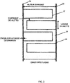
- the figure 3 represents the thermoacoustic system 20 comprising a heat-sound conversion system 21 (first thermo-acoustic device), a transfer medium 22 (for example, the regenerator 11), and a sound-cooling system 23 (second device thermo-acoustic).
- the heat / sound conversion system 21 may receive an input signal from an input acoustic source 24.
- the input signal may be a sound generated by an electroacoustic generator.
- the electroacoustic generator may be piezoelectric.
- An example of an input signal can have a low frequency signal (for example, less than 100 Hertz).
- the heat / sound conversion system 21 may comprise a thermoacoustic cell and the sound / cold conversion system 23 may comprise another thermoacoustic cell.
- thermoacoustic system 20 comprising a first thermoacoustic cell 26a and a second thermoacoustic cell 26b.
- Each thermo-acoustic cell may comprise a heat exchanger on each side of a stack.
- Stacking is a solid material with pores that allow a gaseous fluid to oscillate while in contact with the solid material.
- the stack may be formed of multiple layers or rows of material spaced closely together.
- the material of the stack can be selected to have a low thermal conductivity and a heat capacity greater than the thermal capacity of the oscillating gas so that the stack temperature is stable. Examples of materials for stacking include various polymers, resins, ceramics and polyethylene terephthalate.
- thermo-acoustic system 20 Depending on the thermal diffusivity of the gas, the heat is diffused through the gas. In other words, the stack facilitates the oscillation of the gas from the sound to be transferred into heat. In a similar way, the introduction of heat into the thermo-acoustic cell increases the oscillation of the gas and amplifies the sound. Both principles are presented in the thermo-acoustic system 20.
- the heat from the exhaust is introduced into the first thermoacoustic cell 26a.
- the energy from the heat amplifies the small acoustic wave signal from the input acoustic source 24 to a larger acoustic wave signal propagating through the transfer medium 22 to the second thermoacoustic cell. 26b.
- Some heat can be lost by an optional heat exchanger downstream of the stack of the first thermoacoustic cell 26a.
- the larger acoustic wave signal propagates through the transfer medium 22.
- the transfer medium 22 may comprise a solid, a liquid or a gas.
- the medium of the transfer medium 22 is a noble gas such as helium.
- the acoustic wave signal can have a power of the order of 1-100 kilowatts (kW), for example 10 kW.
- the larger acoustic wave signal can be minimally attenuated by the transfer medium 22.
- the larger acoustic wave signal arrives at the second thermo-acoustic cell 26b, some heat can be lost initially at the optional heat exchanger upstream of the stack of the second thermo-acoustic cell 26b. .
- the larger acoustic wave signal oscillates the gas in the stack of the second thermo-acoustic cell 26b causing an inward heat flow. The heat flows from the refrigeration unit 26 into the second thermo-acoustic cell 26b.
- the optional resonator 25 defines a stationary wave for the thermoacoustic system 20.
- the resonance frequency of the resonator 25 depends on the dimensional characteristics of the tube or chamber.
- the frequency of the input acoustic source 24 and the material and the dimensions of the transfer medium 22 can be selected on the basis of the resonance frequency of the resonator 25.
- the temperature of the refrigeration unit 26 is lowered by the heat exchanger downstream of the stack of the second thermo-acoustic cell 26b.
- the heat is pumped out of the refrigeration unit 28 into the heat exchanger.
- the refrigeration unit 28 can cool water or other refrigerant for the drive system 40.
- the figure 5 is another example of an engine and a thermo-acoustic system.
- the heat-sound conversion system 21 may comprise multiple thermoacoustic stages.
- Each thermo-acoustic stage may comprise a stack with adjacent heat exchangers, as described above.
- Each stage can have a reducing effect in terms of efficiency. For example, the efficiency of the first stage is greater than the yield of the second stage, and so on. However, the overall efficiency increases as the number of stages increases.
- each thermo-acoustic stage may be coupled to an exhaust heat exchanger or radiator which transfers heat from the gases or the exhaust pipe to the respective thermo-acoustic stage.
- the multiple thermo-acoustic stages can be housed in the same enclosure.
- An example of dimensions for the enclosure may be a cylinder having a height of 40 to 100 cm (for example, 60 cm) and a diameter of 40-100 cm (for example, 60 cm).
- An example of number of stages is three, as shown on the figure 5 .
- An example of pressure variation between the inlet on the first stage and the outlet of the final stage can be 40 bars.
- An example of power variation between the input on the first stage and the output of the final stage can be 20-40 kW.
- the inputs to the heat / sound conversion system 21 are the heat from the exhaust and an acoustic wave with a nominal power level.
- the output of the heat-sound conversion system 21 is the amplified acoustic wave transmitted to the sound-cooling conversion system 23.
- the sound-cooling conversion system although represented with a single stage, may also comprise multiple thermo-acoustic floors. Each thermo-acoustic stage may comprise a stack with adjacent heat exchangers, as described above.
- the enclosure of the sound / cold conversion system can be a cylinder of 20-40 cm high and having a diameter of 40-100 cm (for example, 60 cm).
- the output of the sound / cool conversion system 23 cools the inlet water for the internal combustion engine. In other words, the sound / cool conversion system 23 pumps the heat to itself, cooling the water or the inlet liquid through the heat exchanger or radiator.
- the Figure 6A represents an example of a three-stage thermo-acoustic system.
- Each of the first stage, the second stage and the third stage comprises a cold heat exchanger 10, a regenerator 11 and a hot heat exchanger 30.
- the thermoacoustic system can be enclosed in an insulated container.
- the stages are connected by a tube 31 which carries the working gas and the acoustic wave.
- the final heat exchanger 33 prevents heat leakage by heat exchange outside the insulated container.
- the three stages of the thermo-acoustic system can be selected to deliver the maximum net acoustic power.
- One, two, or four storeys or more can be used in the thermo-acoustic system.
- the performance of the three stages affects the performance of the drive system 40 and the generator 100.
- thermo-acoustic system increases the efficiency of the drive system 40 by 10%, which means that the thermo-acoustic system delivers a net electric power (P) (for example, 14 kW).
- P net electric power
- e efficiency
- Table 1 lists examples of dimensions and temperatures for the three stages of the thermo-acoustic system.
- the temperature of the phase change material can not exceed a critical temperature T (eg 380 ° C). Heat can be extracted in the first and second recuperators while maintaining a high temperature in the first and second heat exchangers.
- the available heat is the heat that can be extracted from the flue gases without reaching the dew point temperature D (180 ° C).
- the properties of the exhaust gases are detailed in Table 2. ⁇ u> TABLE 2 ⁇ / u> Exhaust gas Exhaust temperature 495.00 ° C Dew temperature 180.00 ° C Density 0.45 kg / m3 Mass flow 0.21 kg / s Isobaric thermal capacity 1180.00 J / kg.K Heat available 78.06 kW
- the characteristics and dimensions that do not change for the three floors are shown in Table 2 .
- the key parameter to obtain the target thermal power is the number of rows or layers in a stage that varies according to the heat exchange surface. Reducing the surface area of the heat exchange surface increases the number of rows or layers in a floor.
- the depth of the heat exchange zone compared to the length of the thermoacoustic system 20, the pressure loss and the flue velocity are used to select the floor design. There is a trade-off between the number of (floors / plates in a floor) and the different geometric and physical constraints. In one example, an area of 600 x 600 square millimeters (mm 2 ) with a single row for the first evaporator, six rows for the second and ten rows for the third. The total depth of three floors can be 600 mm.
- the Figure 6B represents a bidirectional impulse turbine geometry 88.
- the turbine which may be a receiver system in fluid communication with any of the feedback systems described below (e.g. Figure 7B , figure 9 ).
- the inertance represents a pressure difference in the fluid in order to vary a flow rate over time. Flexibility or compliance represents the resistance or ease with which the fluid is compressed. At the same time, the inertness and flexibility can produce acoustic oscillations similar to the electrical oscillations of an inductance and a capacitance in an AC electrical circuit.
- the Figure 7A represents a thermoacoustic system 20 which is cylindrical.
- the first, second and third floors are arranged vertically. This has the advantage to be adapted for the use of standard components and to make it possible to produce pressure vessels but also to reduce conductive heat loss by reducing the thickness between the different parts of the thermo-acoustic line.
- the Figure 7B represents a thermoacoustic system 20 comprising the bidirectional turbine geometry 88 shown in FIG. Figure 6B , a feedback system 91 and a turbine 95.
- the feedback system 91 may comprise a spiral tube for the recirculation of the working gas through the thermo-acoustic system 20.
- the turbine 95 may comprise a rotor with symmetrical blades which are surrounded by two sets of guide vanes. The shapes of the blades may be selected on the basis of the type of fluid or working gas or the density of the fluid or working gas.
- the feedback system 91 may be in communication with a receiver system such as the turbine 88 of the Figure 6B .
- the turbine can be bidirectional. Turbine performance (bidirectional) depends, among other parameters, on the density of the working fluid. Thermo-acoustic motors can operate at high average pressures up to 40 bar and this high gas density can increase turbine efficiency up to 85%. This makes bidirectional turbines an economical and flexible candidate for converting the generated acoustic power into electricity.
- the figure 8 represents another feedback system 91 or an acoustic feedback configuration.
- the feedback system may comprise an inlet tube 92, an outlet tube 93 and a feedback tube 94.
- the dimensions of the inlet tube 92 may be selected to correspond to the thermo-acoustic system 20.
- the dimensions of the tube Input 92 can be selected to correspond to the resonant frequency of the thermo-acoustic system 20.
- the outlet tube 93 is connected to the cooling system 60 of the generator 100 and to the feedback tube 94.
- the feedback tube 94 returns the gas to the inlet tube 92 for an additional traversing of the thermoacoustic system 20.
- An output 97 of the feedback system 91 may be in communication with a receiving system such as the turbine of the Figure 6B .
- the acoustic feedback configuration delivers 14 kW of electrical power, when the turbine has a yield of 80%.
- the system can extract 60 kW of thermal flux (77% of the available thermal flux) with an overall thermal efficiency of 24%.
- the exergy yield of the system can be equal to 41% (Carnot is calculated according to the highest temperature (495 ° C) and the lowest temperature (37 ° C) of the system).
- Table 3 shows the performance of the acoustic feedback configuration.
- the figure 9 is another example of an engine and a thermo-acoustic system.
- the heat-sound conversion system 21 functions similarly to the foregoing descriptions, but instead of the sound-cooling conversion system 23, the system includes a mechano-electric conversion system 55 (for example, a turbine ).
- the mechanical-electrical conversion system 55 may correspond to the turbine 55 of the Figure 7B and / or at the turbine of the Figure 6B .
- the electro-electrical conversion system 55 may be combined with any of the embodiments described herein.
- the mechanical-electrical conversion system 55 may be a turbine such as a bidirectional turbine that generates electricity from the amplified acoustic signal.
- the pressure from the sound waves can turn a turbine, or oscillate a crankshaft and a piston, which rotate a tree.
- the rotation can rotate a rotor and / or armature winding and generate electrical power.
- the electric power can be used as an additional component of the electrical power of the generator 100.
- the electrical power can be converted into direct current, which can supply an auxiliary system of the generator 100.
- An example of an auxiliary system is the control panel or a display for the generator 100.
- the electric power can control an exciter or a field winding for the generator 100.
- the figure 10 is another illustration of a drive system and a thermo-acoustic system.
- the system includes a secondary cooling source 61.
- the secondary cooling source 61 may be necessary because of the time that may be required. be necessary for the thermoacoustic system 20 to reach a stable state.
- the second cooling source 61 can supplement the primary cooling of the thermo-acoustic system when conditions are ineffective or additional cooling is required.
- the figure 11 is another illustration of an engine and a thermo-acoustic system.
- the system of figure 11 comprises a controller 70 and a switch 71.
- the controller 70 may include a thermometer or thermistor to monitor the temperature of the exhaust gas.
- the controller 70 may control the switch 71 to turn on or off the thermoacoustic system.
- the switch 71 may include a mechanical valve that variably controls the flow of exhaust from the engine 40 to the heat exchanger 10 or to the exhaust system 72.
- the switch 71 may include an electrical switch that turn on and off the sound source.
- the controller 71 can compare the temperature of the exhaust with one or more thresholds.
- the thermo-acoustic system can be used only in a predetermined temperature range.
- the amount of exhaust gas that can be diverted to the thermo-acoustic system may be a function of temperature.
- the drive system 40 may begin to run at a lower temperature, when the exhaust gas reach the temperature threshold, the controller 70 and the switch 71 switch the exhaust of the exhaust system 72 to the heat exchanger 10, and finally to the thermo-acoustic system 20.
- the controller 70 can identify when the exhaust temperature becomes too high and may damage the heat exchanger 10 or the thermo-acoustic system 20.
- the temperature is measured at another portion. of the generator 100 such as the alternator 50.
- the temperature of the alternator 50 can be calculated on the basis of a resistance measurement in the coils of the alternator 50 or calculated on the basis of an output or load on the generator. alternator 50.
- the controller 71 is physically coupled to the generator 100.
- the controller 71 may be included in a control panel mounted on or near the generator 100.
- the controller 71 is remote from the generator 100 and the controller 71 remotely monitors the generator 100, the drive system 40, the thermo-acoustic system 20, the cooling system 60 or the exhaust.
- the generator 100 may be located in an installation (eg factory, ship) and the controller 71 is located in a control room or control facility.
- the generator 100 may comprise a device or a communication interface. Communication between the controller 71 and the generator may be wired or wireless.
- the communication interface of the generator 100 can be associated with an Internet protocol address and the communication is carried out over the Internet.
- the communication interface of the generator 100 and the control device 71 may be configured for communication using the family of known protocols such as Bluetooth ®, the family of known protocols such as 802.11, cellular communication or other wireless communication.
- the control device 71 can also receive additional entries from one or more users.
- User input can provide commands to switch completely or partially exhaust exhaust 72 on the thermo-acoustic system 20.
- the user input may specify a mode for operating the thermoacoustic system 20 or the switch 71.
- the mode may be a yield mode which optimizes the degree of channeling of the exhaust to the thermo-acoustic system 20.
- the mode can be a mode of performance which selects the most effective times for switching the exhaust on the thermo-acoustic system 20.
- the controller 71 may locally monitor or remotely monitor external input parameters for partial or total switching of the evacuation 72 to the thermo-acoustic system 20.
- Input parameters external may include properties of a distribution service system connected to the generator 100.
- the distribution service system properties may include whether or not the distribution service provides electricity to a system including the generator 100, a degree of application of electricity, a cost of electricity at a present time, a power factor at the present time or other properties.
- Controls for the controller 71 may also be received directly from the distribution service system. The controller 71 may determine whether to connect the thermoacoustic system 20 based on the properties of the distribution service.
- the figure 12 represents multiple generating groups 100A-C.
- Generator groups 100A-C may be connected to a common bus to deliver power to a common load.
- Generator groups 100A-C can be synchronized or paralleled.
- the generator sets 100A-C can share a thermo-acoustic system.
- the exhaust lines of generator sets 100A-C may be physically connected to heat exchanger 10, thermoacoustic system 20 and a cooling system 160 described above.
- the cooling system 160 can cool one, some or all of the engines of the generator sets 100A-C.
- different combinations of generator sets 100A-C are connected by controller 70 and switch 71 as a function of temperature.
- the controller 70 may selectively control which generator sets 100A-C are cooled by the cooling system 160.
- Additional components of the drive system 40 may include a manifold, one or more cylinders, a fuel supply, a cruise control, a lubrication system and a starter.
- the switch 71 can turn on and off the input sound source 25 to coincide with the exhaust gases that are diverted to the thermo-acoustic system.
- the controller 70 can selectively connect and disconnect the thermoacoustic system 20 from generator sets 100A-C at different degrees depending on one or more inputs including, but not limited to remote commands, distribution service properties, user commands, and sensor measurements.
- the controller 70 and a switching network can independently connect and disconnect the generator sets 100A-C.
- one or more of the generator sets 100A-C may be connected to the thermoacoustic system 20 at the same time that one or more other generator sets 100A-C are not connected.
- the connection model can be based on individual measurements made by the generator sets 100A-C or specific commands received for individual generator sets.
- the thermoacoustic system 20 can be connected to one of the generator groups 100A-C which can benefit the most from the thermo-acoustic system 20.
- the switching network can connect only the generator group with the highest exhaust temperature.
- the controller 70 may comprise a processor 300, an input device 305, a communication interface 303, a memory 302, and a display.
- the display may be integrated with the computing device or provided by a workstation 309.
- the database 307 may include parameters for the thermoacoustic system 20. Additional, different or fewer components may be included.
- the detection circuit 311 may be a thermometer or a thermistor as explained above.
- the processor 300 can control the switch 71 or another aspect of the thermoacoustic system 20 depending on the output of the detection circuit 311.
- Other types of sensors for the detection circuit 311 are gas detectors, movement, temperature sensors, pressure sensors and internal sensors of the motor. Examples of detectors gas may comprise one or more of an oxygen sensor, a carbon dioxide detector, a carbon monoxide detector or an emission detector.
- the processor 300 may control the switch 71 or thermoacoustic system 20 based on the output of any of these sensors.
- the processor 300 may include a general processor, a digital signal processor, an application specific integrated circuit (ASIC), a user programmable gate array (FPGA), an analog circuit, a digital circuit, combinations of these or any other processor currently known or developed later.
- the memory 302 may be a volatile memory or a non-volatile memory.
- the memories may include one or more of a read only memory (ROM), random access memory (RAM), flash memory, electrically erasable programmable read only memory (EEPROM), or other type of memory.
- the memory 201 may be removable relative to the control device 302 and the memory 15 may be removable relative to the motor, such as a secure digital memory card (SD).
- SD secure digital memory card
- the communication interface 303 may comprise a physical interface, an electrical interface and / or a data interface.
- the communication interface 303 provides wireless and / or cable communications in any format currently known or further developed.
- the communication interface 303 may include any usable connection.
- An exploitable connection may be one in which signals, physical communications, and / or logical communications may be transmitted and / or received.
- An exploitable connection may include a physical interface, an electrical interface, and / or a data interface.
- the communication interface 303 may be connected to a network.
- the network may include wired networks (eg, Ethernet), wireless networks, or combinations thereof.
- the wireless network can be a cellular telephone network, an 802.11, 802.16, 802.20 or WiMax ® network .
- the network can be a public network, such as the Internet, a private network, such as an intranet, or a combination thereof, and can use a variety of networking protocols now. available or further developed including, but not limited to, TCP / IP based networking protocols.
- non-transitory computer readable medium which may be a single medium or multiple media, such as a centralized or distributed database and / or caches and servers. associates who store one or more sets of instructions.
- computer-readable non-transitory media shall also include any medium, except a signal in itself, that is capable of storing, encoding, or transporting a set of instructions for execution by a processor or that causes to any computer system any one or more of the methods or operations described herein.
- the computer readable medium may comprise a semiconductor memory such as a memory card or other container which houses one or more non-volatile read-only memories.
- the computer readable medium may be a RAM or other volatile rewritable memory.
- the computer-readable medium may comprise a magneto-optical medium or an optical medium, such as a disk or tapes or other storage device for capturing carrier wave signals such as a signal communicated on a medium of transmission.
- a digital file attached to an email or other archive or set of autonomous information archives may be considered a distribution medium that is a tangible storage medium. Therefore, the description is considered to include any one or more of a computer readable medium or a distribution medium and other equivalent media and successors upon which data or instructions may be stored.
- the computer readable medium may be non-transient, which includes all tangible computer readable media.
- dedicated hardware implementations such as application-specific integrated circuits, programmable logic networks, and other hardware devices, may be constructed to implement one or more of the methods described herein.
- Applications that may include the apparatus and systems of various embodiments may generally include a variety of electronic and computer systems.
- a or more embodiments described herein may implement functions using at least two specific interconnected hardware modules or devices with associated control and data signals that may be communicated between and across the modules, or as portions of a application-specific integrated circuit. As a result, this system covers software, firmware and hardware implementations.
Abstract
La présente invention concerne un appareil comprenant un système d'échappement, un système de refroidissement (60) et au moins deux dispositifs thermo-acoustiques (20). Un premier dispositif thermo-acoustique est configuré pour convertir une énergie thermique provenant du système d'échappement pour amplifier une onde acoustique. Un deuxième dispositif thermo-acoustique est configuré pour convertir une énergie dans l'onde acoustique amplifiée en une entrée pour le système de refroidissement (60). L'appareil peut être incorporé ou en communication avec un moteur ou un générateur (100).The present invention relates to an apparatus comprising an exhaust system, a cooling system (60) and at least two thermoacoustic devices (20). A first thermoacoustic device is configured to convert thermal energy from the exhaust system to amplify an acoustic wave. A second thermoacoustic device is configured to convert energy in the amplified acoustic wave to an input for the cooling system (60). The apparatus may be incorporated or in communication with a motor or generator (100).
Description
La présente invention concerne en général une source de refroidissement par énergie acoustique et, dans certains exemples, un refroidissement par énergie acoustique dans un parcours entre un système d'échappement et un système d'admission d'un moteur ou générateur.The present invention generally relates to an acoustic energy cooling source and, in some instances, acoustic energy cooling in a path between an exhaust system and an intake system of an engine or generator.
Un générateur ou un groupe électrogène peut comprendre un système d'entraînement, tel qu'un moteur ou une turbine, et un alternateur ou un autre dispositif pour générer une puissance ou de l'énergie électrique. Un ou plusieurs générateurs peuvent fournir une puissance à une charge à travers un bus de générateur et des disjoncteurs ou d'autres types de commutateurs. Un système de générateur comprenant au moins deux générateurs peut être connecté à un bus de générateur et à d'autres générateurs à travers des disjoncteurs. Chaque générateur peut comprendre un dispositif de commande de générateur local qui gère les disjoncteurs et les opérations de mise en parallèle avec les autres générateurs.A generator or generator may comprise a drive system, such as a motor or turbine, and an alternator or other device for generating power or electrical energy. One or more generators can provide power to a load through a generator bus and circuit breakers or other types of switches. A generator system comprising at least two generators can be connected to a generator bus and other generators through circuit breakers. Each generator may include a local generator controller that manages the circuit breakers and the paralleling operations with the other generators.
L'entrée pour le groupe générateur est le combustible et l'air. La sortie primaire est l'électricité et des sorties secondaires comprennent les gaz d'échappement et la chaleur. L'air et le combustible brûlent pour former des gaz d'échappement comprenant des sous-produits de combustion tels que la vapeur d'eau, le dioxyde de carbone et l'azote. Pour maximiser le rendement du groupe générateur, le moteur est refroidi à partir d'une variété de techniques. Toutefois, le système de refroidissement nécessite de l'énergie provenant d'une autre source. Cependant, quand l'eau froide n'est pas abondante, des défis demeurent pour fournir des mécanismes efficaces et effectifs pour refroidir le moteur et le générateur.The input for the generating set is fuel and air. The primary output is electricity and secondary outlets include exhaust and heat. Air and fuel burn to form exhaust gases including combustion byproducts such as water vapor, carbon dioxide and nitrogen. To maximize generator output, the motor is cooled from a variety of techniques. However, the cooling system requires energy from another source. However, when cold water is not abundant, challenges remain to provide efficient and effective mechanisms for cooling the engine and generator.
La présente invention répond à ce besoin en proposant un moteur comprenant :
- un système d'échappement ;
- un système de refroidissement ;
- un premier dispositif thermo-acoustique configuré pour convertir une énergie thermique provenant du système d'échappement pour amplifier une onde acoustique ; et
- un deuxième dispositif thermo-acoustique configuré pour convertir une énergie dans l'onde acoustique amplifiée en une entrée pour le système de refroidissement
- an exhaust system;
- a cooling system;
- a first thermoacoustic device configured to convert thermal energy from the exhaust system to amplify an acoustic wave; and
- a second thermoacoustic device configured to convert energy in the amplified acoustic wave into an input for the cooling system
Selon un mode de réalisation, l'entrée pour le système de refroidissement refroidit l'air admis dans un ou plusieurs cylindres du moteur.According to one embodiment, the inlet for the cooling system cools the air admitted into one or more cylinders of the engine.
Selon un mode de réalisation, le premier dispositif thermo-acoustique comprend au moins un amplificateur de conversion chaleur/son en connexion thermique avec au moins un échangeur de chaleur du système d'échappement.According to one embodiment, the first thermoacoustic device comprises at least one heat / sound conversion amplifier in thermal connection with at least one heat exchanger of the exhaust system.
Selon un mode de réalisation, au moins un échangeur de chaleur comprend un radiateur.According to one embodiment, at least one heat exchanger comprises a radiator.
Selon un mode de réalisation, l'amplificateur de conversion chaleur/son comprend un empilement de plaques parallèles de matériau poreux.According to one embodiment, the heat / sound conversion amplifier comprises a stack of parallel plates of porous material.
Selon un mode de réalisation, le deuxième dispositif thermo-acoustique comprend un système de conversion son/froid.According to one embodiment, the second thermoacoustic device comprises a sound / cold conversion system.
Selon un mode de réalisation, un tel moteur comprend en outre un milieu de transfert entre le premier dispositif thermo-acoustique et le deuxième dispositif thermo-acoustique.According to one embodiment, such a motor further comprises a transfer medium between the first thermo-acoustic device and the second thermo-acoustic device.
Selon un mode de réalisation, le milieu de transfert comprend un gaz noble.According to one embodiment, the transfer medium comprises a noble gas.
Selon un mode de réalisation, le premier dispositif thermo-acoustique comprend une pluralité d'étages thermo-acoustiques.According to one embodiment, the first thermoacoustic device comprises a plurality of thermoacoustic stages.
La présente invention concerne également un générateur comprenant :
- un système d'entraînement ;
- un alternateur entraîné par le système d'entraînement ;
- un système d'échappement ;
- un système de refroidissement ;
- un premier dispositif thermo-acoustique configuré pour convertir une énergie thermique provenant du système d'échappement pour amplifier une onde acoustique ; et
- un deuxième dispositif thermo-acoustique configuré pour convertir une énergie dans l'onde acoustique amplifiée en une entrée pour le système de refroidissement.
- a training system;
- an alternator driven by the drive system;
- an exhaust system;
- a cooling system;
- a first thermoacoustic device configured to convert thermal energy from the exhaust system to amplify an acoustic wave; and
- a second thermoacoustic device configured to convert energy in the amplified acoustic wave into an input for the cooling system.
Selon un mode de réalisation, l'entrée pour le système de refroidissement refroidit de l'air admis dans un ou plusieurs cylindres du moteur.According to one embodiment, the inlet for the cooling system cools air admitted into one or more cylinders of the engine.
Selon un mode de réalisation, le premier dispositif thermo-acoustique comprend au moins un amplificateur de conversion chaleur/son en connexion thermique avec au moins un échangeur de chaleur du système d'échappement.According to one embodiment, the first thermoacoustic device comprises at least one heat / sound conversion amplifier in thermal connection with at least one heat exchanger of the exhaust system.
Selon un mode de réalisation, le deuxième dispositif thermo-acoustique comprend un système de conversion son/froid.According to one embodiment, the second thermoacoustic device comprises a sound / cold conversion system.
Selon un mode de réalisation, un tel générateur comprend en outre un milieu de transfert entre le premier dispositif thermo-acoustique et le deuxième dispositif thermo-acoustique.According to one embodiment, such a generator further comprises a transfer medium between the first thermo-acoustic device and the second thermo-acoustic device.
Selon un mode de réalisation, le premier dispositif thermo-acoustique comprend une pluralité d'étages thermo-acoustiques.According to one embodiment, the first thermoacoustic device comprises a plurality of thermoacoustic stages.
La présente invention concerne enfin un ensemble de générateurs comprenant :
- un système d'échappement pour l'ensemble de générateurs ;
- un système de refroidissement pour l'ensemble de générateurs ;
- un premier dispositif thermo-acoustique configuré pour convertir une énergie thermique provenant du système d'échappement pour amplifier une onde acoustique ; et
- un deuxième dispositif thermo-acoustique configuré pour convertir une énergie dans l'onde acoustique amplifiée en une entrée pour le système de refroidissement.
- an exhaust system for the generator set;
- a cooling system for the set of generators;
- a first thermoacoustic device configured to convert thermal energy from the exhaust system to amplify an acoustic wave; and
- a second thermoacoustic device configured to convert energy in the amplified acoustic wave into an input for the cooling system.
A titre d'exemple, des mises en oeuvre sont décrites ci-après en référence aux dessins annexés.
- La
figure 1 représente un exemple de système de conversion d'énergie pour un générateur. - La
figure 2 représente un exemple d'échangeur de chaleur à haut rendement. - La
figure 3 représente un exemple de système thermo-acoustique. - La
figure 4 représente un autre exemple de système thermo-acoustique. - La
figure 5 représente un autre exemple d'un moteur et d'un système thermo-acoustique. - La
figure 6A représente un exemple de système thermo-acoustique à trois états. - La
figure 6B représente une turbine bidirectionnelle à mouvement de flux acoustique. - La
figure 7A représente un système thermo-acoustique cylindrique. - La
figure 7B représente un exemple de système thermo-acoustique 20 comprenant une turbine bidirectionnelle. - La
figure 8 représente un exemple de configuration de rétroaction acoustique. - La
figure 9 représente un autre exemple d'un moteur et d'un système thermo-acoustique. - La
figure 10 représente un exemple de moteur et de système thermo-acoustique. - La
figure 11 représente un exemple de système d'entraînement et de système thermo-acoustique. - La
figure 12 représente un exemple d'un ensemble de groupes générateurs. - La
figure 13 représente un exemple de dispositif de commande pour n'importe lequel des systèmes ci-dessus.
- The
figure 1 represents an example of an energy conversion system for a generator. - The
figure 2 represents an example of a high efficiency heat exchanger. - The
figure 3 represents an example of a thermo-acoustic system. - The
figure 4 represents another example of a thermo-acoustic system. - The
figure 5 represents another example of an engine and a thermo-acoustic system. - The
Figure 6A represents an example of a three-state thermo-acoustic system. - The
Figure 6B represents a bidirectional turbine with acoustic flow movement. - The
Figure 7A represents a cylindrical thermo-acoustic system. - The
Figure 7B represents an example of athermoacoustic system 20 comprising a bidirectional turbine. - The
figure 8 represents an example of an acoustic feedback configuration. - The
figure 9 represents another example of an engine and a thermo-acoustic system. - The
figure 10 represents an example of engine and thermo-acoustic system. - The
figure 11 represents an example of a drive system and thermo-acoustic system. - The
figure 12 represents an example of a set of generating groups. - The
figure 13 represents an exemplary control device for any of the above systems.
Un système de refroidissement pour un générateur ou un moteur peut refroidir l'air d'admission circulant dans les cylindres du moteur. Le système d'entraînement peut également être refroidi pour maintenir des températures critiques pour les composants du système d'entraînement et l'huile ou les lubrifiants qui recouvrent les composants mobiles du système d'entraînement (par exemple, les pistons) et réduire la friction. Des exemples de mécanismes pour refroidir le système d'entraînement comprennent des radiateurs, qui peuvent être refroidis par air ou refroidis par liquide. Le liquide, ou réfrigérant de moteur, peut être l'eau, surtout quand l'eau froide est abondante (par exemple, des applications marines près d'une étendue d'eau). En variante, un système de refroidissement par eau peut effectuer une recirculation de l'eau à travers le système de refroidissement. L'eau peut être refroidie par l'atmosphère ou une autre source, chauffée par le système d'entraînement, et le processus est répété.A cooling system for a generator or engine can cool the intake air flowing in the engine cylinders. The drive system can also be cooled to maintain critical temperatures for drive system components and oil or lubricants that cover moving components of the drive system (eg, pistons) and reduce friction . Examples of mechanisms for cooling the drive system include radiators, which can be air-cooled or liquid-cooled. Liquid, or engine coolant, can be water, especially when cold water is plentiful (for example, marine applications near a body of water). Alternatively, a water cooling system may recirculate the water through the cooling system. The water can be cooled by the atmosphere or another source, heated by the drive system, and the process is repeated.
Les modes de réalisation suivants utilisent des dispositifs thermo-acoustiques pour transporter de l'énergie pour le système de refroidissement en utilisant une onde acoustique longitudinale pour faciliter une interaction entre des variations de température, de densité et de pression. Le son est une variation de pression et un mouvement d'oscillation d'un milieu (par exemple, air, gaz, liquide ou solide). Les sons peuvent être provoqués par la température (par exemple, la chaleur). La chaleur est transférée en son et le son peut être transféré en mouvement ou une autre forme d'énergie pour générer une énergie de refroidissement.The following embodiments use thermoacoustic devices to transport energy for the cooling system using a longitudinal acoustic wave to facilitate interaction between temperature, density and pressure variations. Sound is a variation of pressure and an oscillating movement of a medium (for example, air, gas, liquid or solid). Sounds can be caused by temperature (for example, heat). The heat is transferred to sound and the sound can be transferred into motion or some other form of energy to generate cooling energy.
Les modes de réalisation suivants fournissent des systèmes et des procédés pour exploiter l'énergie dans l'échappement d'un système d'entraînement comme la chaleur pour entraîner un système thermo-acoustique qui convertit l'énergie pour fournir une entrée pour le système de refroidissement du système d'entraînement ou l'admission d'air du moteur.The following embodiments provide systems and methods for harnessing the energy in the exhaust of a drive system such as heat to drive a thermo-acoustic system that converts energy to provide a thermal energy. inlet for the cooling system of the drive system or the air intake of the engine.
La
Le système d'entraînement 40 pour la conversion mécanique-électrique peut être un moteur à combustion interne ou une turbine. La turbine peut comprendre un rotor avec des pales symétriques. Un fluide en mouvement agit sur les pales symétriques pour communiquer une énergie de rotation à un rotor ou arbre. Dans le moteur à combustion interne, une combustion de combustible dans le moteur applique une force à un ou plusieurs pistons qui font tourner un arbre. Dans l'un ou l'autre exemple, la force de rotation fait tourner l'alternateur 50, qui convertit l'énergie mécanique en énergie électrique pour alimenter la charge 51 en électricité.The
En plus de la production d'énergie mécanique pour l'alternateur 50, le système d'entraînement 40 produit un échappement. L'échappement comprend de la chaleur. L'échappement quitte le système d'entraînement 40 à travers un tube d'échappement 41. Des exemples de températures pour l'échappement peuvent être de 200 à 600 degrés Celsius. La température de l'échappement peut dépendre du combustible du système d'entraînement 40. Des exemples de combustibles comprennent l'essence, le kérosène, le carburant diesel, le gaz de pétrole liquéfié (GPL) ou des combustibles gazeux tels que l'hydrogène, le gaz naturel, le biogaz ou un autre gaz.In addition to the generation of mechanical energy for the
Le régénérateur 11 peut être un milieu de stockage thermique pris en sandwich entre l'échangeur de chaleur 10 et l'échangeur de chaleur 30. Le rôle des échangeurs de chaleur est soit d'ajouter de la chaleur au gaz de travail du système thermo-acoustique 20, ce qui est le cas d'un échangeur de chaleur chaud tel que l'échangeur de chaleur 10, soit d'enlever de la chaleur du gaz de travail, ce qui est le cas d'un échangeur de chaleur froid tel que l'échangeur de chaleur 30.The
Dans le système thermo-acoustique 20 (cellule thermo-acoustique), l'onde acoustique peut être induite par le gradient de température sur le régénérateur 11, qui est dû à une différence de température entre deux échangeurs de chaleur 10 et 30. Quand il existe déjà une onde acoustique induite ou imposée au régénérateur 11, l'onde acoustique peut être amplifiée à l'intérieur du régénérateur 11.In the thermo-acoustic system 20 (thermo-acoustic cell), the acoustic wave can be induced by the temperature gradient on the
Les échangeurs de chaleur 10 et 30 peuvent être conçus pour ajouter ou enlever de la chaleur au ou du gaz de travail. Les échangeurs de chaleur 10 et 30, à travers le système de refroidissement 60, peuvent enlever de la chaleur de ou refroidir l'air qui est admis dans les cylindres de moteur. Le pourcentage auquel la chaleur est ajoutée ou retirée définit le rendement de l'échangeur de chaleur.
La
L'échangeur de chaleur 10 transfère la chaleur dans l'échappement vers le système thermo-acoustique 20. Dans un premier processus thermo-acoustique, le système thermo-acoustique 20 amplifie une onde acoustique à partir de l'énergie dans la chaleur. Dans un deuxième processus thermo-acoustique, l'onde acoustique amplifiée commande une pompe à chaleur pour enlever la chaleur et provoquer une réfrigération. La réfrigération ou le déficit de chaleur est transféré par l'échangeur de chaleur 30 au système de refroidissement 60.The
La
La
En fonction de la diffusivité thermique du gaz, la chaleur est diffusée à travers le gaz. Autrement dit, l'empilement facilite l'oscillation du gaz provenant du son à transférer en chaleur. De manière analogue, l'introduction de chaleur dans la cellule thermo-acoustique augmente l'oscillation du gaz et amplifie le son. Les deux principes sont présentés dans le système thermo-acoustique 20.Depending on the thermal diffusivity of the gas, the heat is diffused through the gas. In other words, the stack facilitates the oscillation of the gas from the sound to be transferred into heat. In a similar way, the introduction of heat into the thermo-acoustic cell increases the oscillation of the gas and amplifies the sound. Both principles are presented in the thermo-
La chaleur provenant de l'échappement est introduite dans la première cellule thermo-acoustique 26a. L'énergie provenant de la chaleur amplifie le petit signal d'onde acoustique provenant de la source acoustique d'entrée 24 à un signal d'onde acoustique plus grand qui se propage à travers le milieu de transfert 22 à la deuxième cellule thermo-acoustique 26b. Une certaine chaleur peut être perdue par un échangeur de chaleur en option en aval de l'empilement de la première cellule thermo-acoustique 26a.The heat from the exhaust is introduced into the first
Le signal d'onde acoustique plus grand se propage à travers le milieu de transfert 22. Le milieu de transfert 22 peut comprendre un solide, un liquide ou un gaz. Dans un exemple, le milieu du milieu de transfert 22 est un gaz noble tel que l'hélium. Le signal d'onde acoustique peut avoir une puissance de l'ordre de 1-100 kilowatts (kW), par exemple 10 kW. Le signal d'onde acoustique plus grand peut être atténué de manière minimale par le milieu de transfert 22.The larger acoustic wave signal propagates through the
Quand le signal d'onde acoustique plus grand arrive à la deuxième cellule thermo-acoustique 26b, une certaine chaleur peut être perdue initialement au niveau de l'échangeur de chaleur en option en amont de l'empilement de la deuxième cellule thermo-acoustique 26b. Le signal d'onde acoustique plus grand fait osciller le gaz dans l'empilement de la deuxième cellule thermo-acoustique 26b en provoquant un flux de chaleur vers l'intérieur. La chaleur s'écoule à partir de l'unité de réfrigération 26 dans la deuxième cellule thermo-acoustique 26b.When the larger acoustic wave signal arrives at the second thermo-
Le résonateur en option 25 permet de définir une onde stationnaire pour le système thermo-acoustique 20. La fréquence de résonance du résonateur 25 dépend des caractéristiques dimensionnelles du tube ou de la chambre. La fréquence de la source acoustique d'entrée 24 et le matériau et les dimensions du milieu de transfert 22 peuvent être sélectionnés sur la base de la fréquence de résonance du résonateur 25.The
La température de l'unité de réfrigération 26 est abaissée par l'échangeur de chaleur en aval de l'empilement de la deuxième cellule thermo-acoustique 26b. La chaleur est pompée hors de l'unité de réfrigération 28 dans l'échangeur de chaleur. L'unité de réfrigération 28 peut refroidir de l'eau ou un autre réfrigérant pour le système d'entraînement 40.The temperature of the refrigeration unit 26 is lowered by the heat exchanger downstream of the stack of the second thermo-
La
Les entrées dans le système de conversion chaleur/son 21 sont la chaleur provenant de l'échappement et une onde acoustique avec un niveau de puissance nominal. La sortie du système de conversion chaleur/son 21 est l'onde acoustique amplifiée transmise au système de conversion son/froid 23. Le système de conversion son/froid, bien qu'il soit représenté avec un seul étage, peut également comprendre de multiples étages thermo-acoustiques. Chaque étage thermo-acoustique peut comprendre un empilement avec des échangeurs de chaleur adjacents, comme décrit ci-dessus. L'enceinte du système de conversion son/froid peut être un cylindre de 20-40 cm de haut et ayant un diamètre de 40-100 cm (par exemple, 60 cm). La sortie du système de conversion son/froid 23 refroidit l'eau d'entrée pour le moteur à combustion interne. En d'autres termes, le système de conversion son/froid 23 pompe la chaleur jusqu'à lui-même, en refroidissant l'eau ou le liquide d'entrée par l'intermédiaire de l'échangeur de chaleur ou du radiateur.The inputs to the heat /
La
Dans un exemple, le système thermo-acoustique augmente le rendement du système d'entraînement 40 de 10 %, ce qui signifie que le système thermo-acoustique délivre une puissance électrique nette (P) (par exemple, 14 kW). Toutefois, en raison du rendement (e) (par exemple, 0,8) de la turbine, le système thermo-acoustique devrait travailler pour délivrer environ une puissance P/e (par exemple, 14kW/0,8 = 17,5 kW). Le tableau 1 liste des exemples de dimensions et de températures pour les trois étages du système thermo-acoustique.

La température du matériau de changement de phase ne peut pas dépasser une température critique T (par exemple, 380 °C). Une chaleur peut être extraite dans les premier et deuxième récupérateurs tout en maintenant une haute température dans les premier et deuxième échangeurs de chaleur. La chaleur disponible est la chaleur qui peut être extraite des gaz de fumées sans atteindre la température de rosée D (180 °C). Les propriétés des gaz d'échappement sont détaillées dans le Tableau 2.
Les caractéristiques et dimensions qui ne changent pas pour les trois étages sont illustrées dans le Tableau 2. Le paramètre clé pour obtenir la puissance thermique cible est le nombre de rangées ou de couches dans un étage qui varie en fonction de la surface d'échange de chaleur. Une réduction de la superficie de la surface d'échange de chaleur augmente le nombre de rangées ou de couches dans un étage. La profondeur de la zone d'échange de chaleur, comparée à la longueur du système thermo-acoustique 20, la perte de pression et la vitesse des fumées sont utilisées pour sélectionner la conception des étages. Il existe un compromis entre le nombre de (étages/plaques dans un étage) et les différentes contraintes géométriques et physiques. Dans un exemple, une superficie de 600 x 600 millimètres carrés (mm2) avec une seule rangée pour le premier évaporateur, six rangées pour le deuxième et dix rangées pour le troisième. La profondeur totale de trois étages peut être de 600 mm.The characteristics and dimensions that do not change for the three floors are shown in Table 2 . The key parameter to obtain the target thermal power is the number of rows or layers in a stage that varies according to the heat exchange surface. Reducing the surface area of the heat exchange surface increases the number of rows or layers in a floor. The depth of the heat exchange zone, compared to the length of the
La
La
La
La turbine peut être bidirectionnelle. La performance des turbines (bidirectionnelles) dépend, parmi d'autres paramètres, de la densité du fluide de travail. Des moteurs thermo-acoustiques peuvent fonctionner à des pressions moyennes élevées jusqu'à 40 bars et cette densité de gaz élevée peut augmenter le rendement de la turbine jusqu'à 85 %. Ceci fait des turbines bidirectionnelles un candidat économique et flexible pour convertir la puissance acoustique générée en électricité.The turbine can be bidirectional. Turbine performance (bidirectional) depends, among other parameters, on the density of the working fluid. Thermo-acoustic motors can operate at high average pressures up to 40 bar and this high gas density can increase turbine efficiency up to 85%. This makes bidirectional turbines an economical and flexible candidate for converting the generated acoustic power into electricity.
La
Dans un exemple, la configuration de rétroaction acoustique délivre 14 kW de puissance électrique, quand la turbine a un rendement de 80 %. Le système peut extraire 60 kW de flux thermique (77 % du flux thermique disponible) avec un rendement thermique global de 24 %. Le rendement exergétique du système peut être égal à 41 % (Carnot est calculé en fonction de la plus haute température (495 °C) et de la plus basse température (37 °C) du système). Le Tableau 3 indique la performance de la configuration de rétroaction acoustique.
La
Le système de conversion mécano-électrique 55 peut être combiné avec n'importe lequel des modes de réalisation décrits ici. Le système de conversion mécano-électrique 55 peut être une turbine telle qu'une turbine bidirectionnelle qui génère de l'électricité à partir du signal acoustique amplifié. La pression provenant des ondes sonores peut faire tourner une turbine, ou faire osciller un vilebrequin et un piston, qui fait tourner un arbre. La rotation peut faire tourner un rotor et/ou un enroulement d'induit et générer une puissance électrique. La puissance électrique peut être utilisée comme une composante additionnelle de la puissance électrique du générateur 100. La puissance électrique peut être convertie en courant continu, lequel peut alimenter un système auxiliaire du générateur 100. Un exemple de système auxiliaire est le tableau de commande ou un affichage pour le générateur 100. La puissance électrique peut commander un excitateur ou un enroulement de champ pour le générateur 100.The electro-
La
La
Dans un exemple, le dispositif de commande 71 peut comparer la température des gaz d'échappement avec un ou plusieurs seuils. Le système thermo-acoustique peut être utilisé seulement dans une plage de températures prédéterminée. Dans un autre exemple, la quantité de gaz d'échappement qui peut être déviée jusqu'au système thermo-acoustique peut être une fonction de la température. Par exemple, le système d'entraînement 40 peut commencer à tourner à une température inférieure, quand les gaz d'échappement atteignent le seuil de température, le dispositif de commande 70 et le commutateur 71 commutent l'échappement du système d'évacuation 72 à l'échangeur de chaleur 10, et finalement au système thermo-acoustique 20. Dans un autre exemple, le dispositif de commande 70 peut identifier quand la température d'échappement devient trop élevée et peut endommager l'échangeur de chaleur 10 ou le système thermo-acoustique 20. Dans un autre exemple, la température est mesurée au niveau d'une autre portion du générateur 100 telle que l'alternateur 50. La température de l'alternateur 50 peut être calculée sur la base d'une mesure de résistance dans les bobines de l'alternateur 50 ou calculée sur la base d'une sortie ou charge sur l'alternateur 50.In one example, the
Dans un exemple, le dispositif de commande 71 est couplé physiquement au générateur 100. Le dispositif de commande 71 peut être inclus dans un panneau de commande monté sur ou près du générateur 100. Dans un autre exemple, le dispositif de commande 71 est éloigné du générateur 100 et le dispositif de commande 71 surveille à distance le générateur 100, le système d'entraînement 40, le système thermo-acoustique 20, le système de refroidissement 60 ou l'échappement. Par exemple, le générateur 100 peut être situé dans une installation (par exemple, usine, navire) et le dispositif de commande 71 est situé dans une salle de commande ou une installation de commande. Pour faciliter la communication, le générateur 100 peut comprendre un dispositif ou une interface de communication. La communication entre le dispositif de commande 71 et le générateur peut être par câble ou sans fil. L'interface de communication du générateur 100 peut être associée à une adresse de protocole Internet et la communication est effectuée à travers Internet. L'interface de communication du générateur 100 et le dispositif de commande 71 peuvent être configurés pour une communication utilisant la famille de protocoles connue comme Bluetooth®, la famille de protocoles connue comme 802.11, une communication cellulaire ou une autre communication sans fil.In one example, the
En plus ou en variante à l'entrée de données à partir du générateur 100, du système d'entraînement 40, du système thermo-acoustique 20, du système de refroidissement 60 et/ou de l'échappement, le dispositif de commande 71 peut également recevoir des entrées additionnelles provenant d'un ou plusieurs utilisateurs. L'entrée d'utilisateur peut fournir des commandes pour commuter totalement ou partiellement l'échappement de l'évacuation 72 sur le système thermo-acoustique 20. L'entrée d'utilisateur peut spécifier un mode pour faire fonctionner le système thermo-acoustique 20 ou le commutateur 71. Le mode peut être un mode de rendement qui optimise le degré de canalisation de l'échappement vers le système thermo-acoustique 20. Le mode peut être un mode de rendement qui sélectionne les temps les plus efficaces pour commuter l'échappement sur le système thermo-acoustique 20.In addition or alternatively to the data input from the
En plus ou en variante, le dispositif de commande 71 peut surveiller localement ou surveiller à distance des paramètres d'entrée externes à des fins de commutation partielle ou totale de l'évacuation 72 sur le système thermo-acoustique 20. Les paramètres d'entrée externes peuvent comprendre des propriétés d'un système de service de distribution connecté au générateur 100. Les propriétés du système de service de distribution peuvent comprendre le fait que le service de distribution fournit ou non de l'électricité à un système comprenant le générateur 100, un degré d'application de l'électricité, un coût de l'électricité à un instant présent, un facteur de puissance à l'instant présent ou d'autres propriétés. Des commandes pour le dispositif de commande 71 peuvent également être reçues directement du système de service de distribution. Le dispositif de commande 71 peut déterminer le fait de connecter ou non le système thermo-acoustique 20 sur la base des propriétés du service de distribution.In addition or alternatively, the
La
De plus, le dispositif de commande 70 et un réseau de commutation peuvent connecter et déconnecter de manière indépendante les groupes générateurs 100A-C. Précisément, un ou plusieurs des groupes générateurs 100A-C peuvent être connectés au système thermo-acoustique 20 au même moment où un ou plusieurs autres groupes générateurs 100A-C ne sont pas connectés. Le modèle de connexions peut être basé sur des mesures individuelles effectuées par les groupes générateurs 100A-C ou des commandes spécifiques reçus pour des groupes générateurs individuels. Dans un exemple, le système thermo-acoustique 20 peut être connecté à un des groupes générateurs 100A-C qui peut bénéficier le plus du système thermo-acoustique 20. Par exemple, le réseau de commutation peut connecter seulement le groupe générateur avec la plus haute température d'échappement.In addition, the
Comme représenté par la
Le circuit de détection 311 peut être un thermomètre ou une thermistance comme expliqué ci-dessus. Le processeur 300 peut commander le commutateur 71 ou un autre aspect du système thermo-acoustique 20 en fonction de la sortie du circuit de détection 311. D'autres types de capteurs pour le circuit de détection 311 sont des détecteurs de gaz, des détecteurs de mouvement, des capteurs de température, des capteurs de pression et des capteurs internes du moteur. Des exemples de détecteurs de gaz peuvent comprendre un ou plusieurs parmi un détecteur d'oxygène, un détecteur de dioxyde de carbone, un détecteur de monoxyde de carbone ou un détecteur d'émission. Le processeur 300 peut commander le commutateur 71 ou le système thermo-acoustique 20 sur la base de la sortie de n'importe lequel de ces capteurs.The detection circuit 311 may be a thermometer or a thermistor as explained above. The
Le processeur 300 peut comprendre un processeur général, un processeur de signal numérique, un circuit intégré spécifique à une application (ASIC), un réseau de portes programmable par l'utilisateur (FPGA), un circuit analogique, un circuit numérique, des combinaisons de ceux-ci ou n'importe quel autre processeur actuellement connu ou développé ultérieurement. La mémoire 302 peut être une mémoire volatile ou une mémoire non volatile. Les mémoires peuvent comprendre une ou plusieurs parmi une mémoire morte (ROM), une mémoire vive (RAM), une mémoire flash, une mémoire morte programmable et effaçable électriquement (EEPROM) ou un autre type de mémoire. La mémoire 201 peut être amovible par rapport au dispositif de commande 302 et la mémoire 15 peut être amovible par rapport au moteur, telle qu'une carte mémoire numérique sécurisée (SD).The
L'interface de communication 303 peut comprendre une interface physique, une interface électrique et/ou une interface de données. L'interface de communication 303 fournit des communications sans fil et/ou par câble dans n'importe quel format actuellement connu ou développé ultérieurement. En plus des ports d'entrée et des ports de sortie, l'interface de communication 303 peut comprendre n'importe quelle connexion exploitable. Une connexion exploitable peut être une dans laquelle des signaux, des communications physiques et/ou des communications logiques peuvent être transmis et/ou reçus. Une connexion exploitable peut comprendre une interface physique, une interface électrique et/ou une interface de données.The
L'interface de communication 303 peut être connectée à un réseau. Le réseau peut comprendre des réseaux câblés (par exemple, Ethernet), des réseaux sans fil ou des combinaisons de ceux-ci. Le réseau sans fil peut être un réseau téléphonique cellulaire, un réseau 802.11, 802.16, 802.20 ou WiMax®. En outre, le réseau peut être un réseau public, comme Internet, un réseau privé, tel qu'un intranet, ou une combinaison de ceux-ci, et peut utiliser une variété de protocoles de mise en réseau maintenant disponibles ou développés ultérieurement comprenant, mais sans limitation, des protocoles de mise en réseau basés sur TCP/IP.The
N'importe laquelle des techniques décrites ci-dessus peut être mise en oeuvre sur un support non transitoire lisible par ordinateur, qui peut être un support unique ou de multiples supports, comme une base de données centralisée ou distribuée et/ou des caches et serveurs associés qui stockent un ou plusieurs jeux d'instructions. Le terme « support non transitoire lisible par ordinateur » devra également comprendre n'importe quel support, sauf un signal en soi, qui est capable de stocker, coder ou transporter un jeu d'instructions pour l'exécution par un processeur ou qui fait effectuer à un système informatique n'importe lequel, ou plusieurs, des procédés ou opérations décrits ici.Any of the techniques described above may be implemented on a non-transitory computer readable medium, which may be a single medium or multiple media, such as a centralized or distributed database and / or caches and servers. associates who store one or more sets of instructions. The term "computer-readable non-transitory media" shall also include any medium, except a signal in itself, that is capable of storing, encoding, or transporting a set of instructions for execution by a processor or that causes to any computer system any one or more of the methods or operations described herein.
Dans un mode de réalisation exemplaire, non limitatif, particulier, le support lisible par ordinateur peut comprendre une mémoire à semi-conducteurs telle qu'une carte mémoire ou autre contenant qui loge une ou plusieurs mémoires mortes non volatiles. En outre, le support lisible par ordinateur peut être une mémoire vive ou autre mémoire réinscriptible volatile. De plus, le support lisible par ordinateur peut comprendre un support magnéto-optique ou un support optique, tel qu'un disque ou des bandes ou autre dispositif de stockage pour capturer des signaux d'onde porteuse tels qu'un signal communiqué sur un support de transmission. Un fichier numérique joint à un courriel ou autre archive ou ensemble d'archives d'informations autonomes peut être considéré comme un support de distribution qui est un support de stockage tangible. Par conséquent, la description est considérée comme incluant l'un quelconque ou plusieurs parmi un support lisible par ordinateur ou un support de distribution et d'autres supports équivalents et successeurs, sur lesquels des données ou instructions peuvent être stockées. Le support lisible par ordinateur peut être non transitoire, qui comprend tous les supports lisibles par ordinateurs tangibles.In an exemplary, nonlimiting, particular embodiment, the computer readable medium may comprise a semiconductor memory such as a memory card or other container which houses one or more non-volatile read-only memories. In addition, the computer readable medium may be a RAM or other volatile rewritable memory. In addition, the computer-readable medium may comprise a magneto-optical medium or an optical medium, such as a disk or tapes or other storage device for capturing carrier wave signals such as a signal communicated on a medium of transmission. A digital file attached to an email or other archive or set of autonomous information archives may be considered a distribution medium that is a tangible storage medium. Therefore, the description is considered to include any one or more of a computer readable medium or a distribution medium and other equivalent media and successors upon which data or instructions may be stored. The computer readable medium may be non-transient, which includes all tangible computer readable media.
Dans une variante de mode de réalisation, des mises en oeuvre matérielles dédiées, telles que des circuits intégrés spécifiques à l'application, des réseaux logiques programmables et autres dispositifs matériels, peuvent être construits pour mettre en oeuvre un ou plusieurs des procédés décrits ici. Des applications qui peuvent comprendre l'appareil et les systèmes de divers modes de réalisation peuvent généralement comprendre une variété de systèmes électroniques et informatiques. Un ou plusieurs modes de réalisation décrits ici peuvent mettre en oeuvre des fonctions utilisant au moins deux modules ou dispositifs matériels interconnectés spécifiques avec des signaux de commande et de données associés qui peuvent être communiqués entre et à travers les modules, ou comme des portions d'un circuit intégré spécifique à l'application. En conséquence, le présent système couvre des mises en oeuvre par logiciel, microprogramme et matériel.In an alternative embodiment, dedicated hardware implementations, such as application-specific integrated circuits, programmable logic networks, and other hardware devices, may be constructed to implement one or more of the methods described herein. Applications that may include the apparatus and systems of various embodiments may generally include a variety of electronic and computer systems. A or more embodiments described herein may implement functions using at least two specific interconnected hardware modules or devices with associated control and data signals that may be communicated between and across the modules, or as portions of a application-specific integrated circuit. As a result, this system covers software, firmware and hardware implementations.
Claims (16)
Priority Applications (1)
| Application Number | Priority Date | Filing Date | Title |
|---|---|---|---|
| PL15199996T PL3034826T3 (en) | 2014-12-17 | 2015-12-15 | Cooling source using acoustic energy |
Applications Claiming Priority (2)
| Application Number | Priority Date | Filing Date | Title |
|---|---|---|---|
| FR1462661A FR3030701A1 (en) | 2014-12-17 | 2014-12-17 | |
| FR1557309A FR3030644B1 (en) | 2014-12-17 | 2015-07-30 | ACOUSTIC ENERGY COOLING SOURCE |
Publications (2)
| Publication Number | Publication Date |
|---|---|
| EP3034826A1 true EP3034826A1 (en) | 2016-06-22 |
| EP3034826B1 EP3034826B1 (en) | 2019-07-24 |
Family
ID=54834763
Family Applications (1)
| Application Number | Title | Priority Date | Filing Date |
|---|---|---|---|
| EP15199996.8A Active EP3034826B1 (en) | 2014-12-17 | 2015-12-15 | Cooling source using acoustic energy |
Country Status (2)
| Country | Link |
|---|---|
| EP (1) | EP3034826B1 (en) |
| PL (1) | PL3034826T3 (en) |
Citations (4)
| Publication number | Priority date | Publication date | Assignee | Title |
|---|---|---|---|---|
| JP2005233485A (en) * | 2004-02-18 | 2005-09-02 | Toyota Motor Corp | Cooling device for internal combustion engine |
| US20080060364A1 (en) * | 2005-01-07 | 2008-03-13 | The Doshisha | Thermoacoustic Device |
| CN101608847A (en) * | 2008-06-18 | 2009-12-23 | 深圳市中科力函热声技术工程研究中心有限公司 | The thermoacoustic refrigeration system that using waste heat from tail gas of internal combustion engine drives |
| US20110259003A1 (en) * | 2010-04-23 | 2011-10-27 | Honda Motor Co., Ltd. | Thermoacoustic engine |
-
2015
- 2015-12-15 PL PL15199996T patent/PL3034826T3/en unknown
- 2015-12-15 EP EP15199996.8A patent/EP3034826B1/en active Active
Patent Citations (4)
| Publication number | Priority date | Publication date | Assignee | Title |
|---|---|---|---|---|
| JP2005233485A (en) * | 2004-02-18 | 2005-09-02 | Toyota Motor Corp | Cooling device for internal combustion engine |
| US20080060364A1 (en) * | 2005-01-07 | 2008-03-13 | The Doshisha | Thermoacoustic Device |
| CN101608847A (en) * | 2008-06-18 | 2009-12-23 | 深圳市中科力函热声技术工程研究中心有限公司 | The thermoacoustic refrigeration system that using waste heat from tail gas of internal combustion engine drives |
| US20110259003A1 (en) * | 2010-04-23 | 2011-10-27 | Honda Motor Co., Ltd. | Thermoacoustic engine |
Also Published As
| Publication number | Publication date |
|---|---|
| PL3034826T3 (en) | 2020-02-28 |
| EP3034826B1 (en) | 2019-07-24 |
Similar Documents
| Publication | Publication Date | Title |
|---|---|---|
| FR3030644A1 (en) | SOURCE OF COOLING BY ACOUSTIC ENERGY | |
| EP2534357B1 (en) | Thermoacoustic machine having an electric feedback loop | |
| US10801404B2 (en) | Variable pressure turbine | |
| EP2394309B1 (en) | Thermoelectric generation for a gas turbine | |
| EP2326801B1 (en) | Cogeneration device | |
| CA2639217A1 (en) | Electricity generation in a turbine engine | |
| FR3016025A1 (en) | COMBINATION OF A COMPRESSED AIR ENERGY STORAGE UNIT AND A THERMAL POWER PLANT | |
| FR2998265A1 (en) | AIR CONDITIONING METHOD AND SYSTEM FOR AIRCRAFT | |
| EP3034826B1 (en) | Cooling source using acoustic energy | |
| CA3122306A1 (en) | Gas expansion and fluid compression station | |
| FR2971552A1 (en) | Thermo-acoustic machine e.g. wave generator, has power feedback circuit transferring electrical energy generated at outlet of energy conversion system to inlet of another energy conversion system | |
| Di Bella | Gas turbine engine exhaust waste heat recovery using supercritical CO2 Brayton cycle with thermoelectric generator technology | |
| FR3083595A1 (en) | THERMOACOUSTIC MACHINE IN PARTICULAR FOR ENERGY COGENERATION SYSTEMS IN HYBRID VEHICLES | |
| WO2016131917A1 (en) | Thermoacoustic engine | |
| EP3099919A1 (en) | External combustion engine | |
| FR3053401A1 (en) | SYSTEM COMPRISING MEANS FOR COOLING THERMAL MACHINE | |
| WO2014080130A1 (en) | Unit for converting thermal energy into hydraulic energy | |
| FR3049696A1 (en) | DIRECT COMBUSTION THERMOACOUSTIC SYSTEM | |
| WO2022194837A1 (en) | System for the thermal compression of a gas | |
| FR3132736A1 (en) | Heating turbine engine for a fuel conditioning system configured to supply an aircraft turbine engine using fuel from a cryogenic tank | |
| WO2023222971A1 (en) | System for generating cold and for supplying electrical power from seawater and the sun | |
| FR3074234A1 (en) | COOLING SYSTEM | |
| WO2023099185A1 (en) | Thermoacoustic machine with phase-shift modulation | |
| FR3130947A1 (en) | Acoustic power modulation in a thermoacoustic machine | |
| CA3142977A1 (en) | Hybrid solar high-efficiency thermodynamic device and hydrogen-oxygen pair producing a plurality of energies |
Legal Events
| Date | Code | Title | Description |
|---|---|---|---|
| PUAI | Public reference made under article 153(3) epc to a published international application that has entered the european phase |
Free format text: ORIGINAL CODE: 0009012 |
|
| AK | Designated contracting states |
Kind code of ref document: A1 Designated state(s): AL AT BE BG CH CY CZ DE DK EE ES FI FR GB GR HR HU IE IS IT LI LT LU LV MC MK MT NL NO PL PT RO RS SE SI SK SM TR |
|
| AX | Request for extension of the european patent |
Extension state: BA ME |
|
| STAA | Information on the status of an ep patent application or granted ep patent |
Free format text: STATUS: REQUEST FOR EXAMINATION WAS MADE |
|
| 17P | Request for examination filed |
Effective date: 20161219 |
|
| RBV | Designated contracting states (corrected) |
Designated state(s): AL AT BE BG CH CY CZ DE DK EE ES FI FR GB GR HR HU IE IS IT LI LT LU LV MC MK MT NL NO PL PT RO RS SE SI SK SM TR |
|
| STAA | Information on the status of an ep patent application or granted ep patent |
Free format text: STATUS: EXAMINATION IS IN PROGRESS |
|
| 17Q | First examination report despatched |
Effective date: 20170712 |
|
| GRAP | Despatch of communication of intention to grant a patent |
Free format text: ORIGINAL CODE: EPIDOSNIGR1 |
|
| STAA | Information on the status of an ep patent application or granted ep patent |
Free format text: STATUS: GRANT OF PATENT IS INTENDED |
|
| INTG | Intention to grant announced |
Effective date: 20190218 |
|
| GRAS | Grant fee paid |
Free format text: ORIGINAL CODE: EPIDOSNIGR3 |
|
| GRAA | (expected) grant |
Free format text: ORIGINAL CODE: 0009210 |
|
| STAA | Information on the status of an ep patent application or granted ep patent |
Free format text: STATUS: THE PATENT HAS BEEN GRANTED |
|
| AK | Designated contracting states |
Kind code of ref document: B1 Designated state(s): AL AT BE BG CH CY CZ DE DK EE ES FI FR GB GR HR HU IE IS IT LI LT LU LV MC MK MT NL NO PL PT RO RS SE SI SK SM TR |
|
| REG | Reference to a national code |
Ref country code: GB Ref legal event code: FG4D Free format text: NOT ENGLISH |
|
| REG | Reference to a national code |
Ref country code: CH Ref legal event code: EP |
|
| REG | Reference to a national code |
Ref country code: DE Ref legal event code: R096 Ref document number: 602015034208 Country of ref document: DE |
|
| REG | Reference to a national code |
Ref country code: AT Ref legal event code: REF Ref document number: 1158461 Country of ref document: AT Kind code of ref document: T Effective date: 20190815 |
|
| REG | Reference to a national code |
Ref country code: IE Ref legal event code: FG4D Free format text: LANGUAGE OF EP DOCUMENT: FRENCH |
|
| REG | Reference to a national code |
Ref country code: NL Ref legal event code: FP |
|
| REG | Reference to a national code |
Ref country code: LT Ref legal event code: MG4D |
|
| REG | Reference to a national code |
Ref country code: AT Ref legal event code: MK05 Ref document number: 1158461 Country of ref document: AT Kind code of ref document: T Effective date: 20190724 |
|
| PG25 | Lapsed in a contracting state [announced via postgrant information from national office to epo] |
Ref country code: FI Free format text: LAPSE BECAUSE OF FAILURE TO SUBMIT A TRANSLATION OF THE DESCRIPTION OR TO PAY THE FEE WITHIN THE PRESCRIBED TIME-LIMIT Effective date: 20190724 Ref country code: AT Free format text: LAPSE BECAUSE OF FAILURE TO SUBMIT A TRANSLATION OF THE DESCRIPTION OR TO PAY THE FEE WITHIN THE PRESCRIBED TIME-LIMIT Effective date: 20190724 Ref country code: LT Free format text: LAPSE BECAUSE OF FAILURE TO SUBMIT A TRANSLATION OF THE DESCRIPTION OR TO PAY THE FEE WITHIN THE PRESCRIBED TIME-LIMIT Effective date: 20190724 Ref country code: PT Free format text: LAPSE BECAUSE OF FAILURE TO SUBMIT A TRANSLATION OF THE DESCRIPTION OR TO PAY THE FEE WITHIN THE PRESCRIBED TIME-LIMIT Effective date: 20191125 Ref country code: BG Free format text: LAPSE BECAUSE OF FAILURE TO SUBMIT A TRANSLATION OF THE DESCRIPTION OR TO PAY THE FEE WITHIN THE PRESCRIBED TIME-LIMIT Effective date: 20191024 Ref country code: NO Free format text: LAPSE BECAUSE OF FAILURE TO SUBMIT A TRANSLATION OF THE DESCRIPTION OR TO PAY THE FEE WITHIN THE PRESCRIBED TIME-LIMIT Effective date: 20191024 Ref country code: HR Free format text: LAPSE BECAUSE OF FAILURE TO SUBMIT A TRANSLATION OF THE DESCRIPTION OR TO PAY THE FEE WITHIN THE PRESCRIBED TIME-LIMIT Effective date: 20190724 Ref country code: SE Free format text: LAPSE BECAUSE OF FAILURE TO SUBMIT A TRANSLATION OF THE DESCRIPTION OR TO PAY THE FEE WITHIN THE PRESCRIBED TIME-LIMIT Effective date: 20190724 |
|
| PG25 | Lapsed in a contracting state [announced via postgrant information from national office to epo] |
Ref country code: RS Free format text: LAPSE BECAUSE OF FAILURE TO SUBMIT A TRANSLATION OF THE DESCRIPTION OR TO PAY THE FEE WITHIN THE PRESCRIBED TIME-LIMIT Effective date: 20190724 Ref country code: IS Free format text: LAPSE BECAUSE OF FAILURE TO SUBMIT A TRANSLATION OF THE DESCRIPTION OR TO PAY THE FEE WITHIN THE PRESCRIBED TIME-LIMIT Effective date: 20191124 Ref country code: AL Free format text: LAPSE BECAUSE OF FAILURE TO SUBMIT A TRANSLATION OF THE DESCRIPTION OR TO PAY THE FEE WITHIN THE PRESCRIBED TIME-LIMIT Effective date: 20190724 Ref country code: LV Free format text: LAPSE BECAUSE OF FAILURE TO SUBMIT A TRANSLATION OF THE DESCRIPTION OR TO PAY THE FEE WITHIN THE PRESCRIBED TIME-LIMIT Effective date: 20190724 |
|
| REG | Reference to a national code |
Ref country code: GR Ref legal event code: EP Ref document number: 20190403252 Country of ref document: GR Effective date: 20200213 |
|
| REG | Reference to a national code |
Ref country code: ES Ref legal event code: FG2A Ref document number: 2751749 Country of ref document: ES Kind code of ref document: T3 Effective date: 20200401 |
|
| PG25 | Lapsed in a contracting state [announced via postgrant information from national office to epo] |
Ref country code: EE Free format text: LAPSE BECAUSE OF FAILURE TO SUBMIT A TRANSLATION OF THE DESCRIPTION OR TO PAY THE FEE WITHIN THE PRESCRIBED TIME-LIMIT Effective date: 20190724 Ref country code: DK Free format text: LAPSE BECAUSE OF FAILURE TO SUBMIT A TRANSLATION OF THE DESCRIPTION OR TO PAY THE FEE WITHIN THE PRESCRIBED TIME-LIMIT Effective date: 20190724 Ref country code: RO Free format text: LAPSE BECAUSE OF FAILURE TO SUBMIT A TRANSLATION OF THE DESCRIPTION OR TO PAY THE FEE WITHIN THE PRESCRIBED TIME-LIMIT Effective date: 20190724 |
|
| RAP2 | Party data changed (patent owner data changed or rights of a patent transferred) |
Owner name: HEKYOM |
|
| RAP2 | Party data changed (patent owner data changed or rights of a patent transferred) |
Owner name: EQUIUM GROUPE |
|
| PG25 | Lapsed in a contracting state [announced via postgrant information from national office to epo] |
Ref country code: SK Free format text: LAPSE BECAUSE OF FAILURE TO SUBMIT A TRANSLATION OF THE DESCRIPTION OR TO PAY THE FEE WITHIN THE PRESCRIBED TIME-LIMIT Effective date: 20190724 Ref country code: IS Free format text: LAPSE BECAUSE OF FAILURE TO SUBMIT A TRANSLATION OF THE DESCRIPTION OR TO PAY THE FEE WITHIN THE PRESCRIBED TIME-LIMIT Effective date: 20200224 Ref country code: CZ Free format text: LAPSE BECAUSE OF FAILURE TO SUBMIT A TRANSLATION OF THE DESCRIPTION OR TO PAY THE FEE WITHIN THE PRESCRIBED TIME-LIMIT Effective date: 20190724 Ref country code: SM Free format text: LAPSE BECAUSE OF FAILURE TO SUBMIT A TRANSLATION OF THE DESCRIPTION OR TO PAY THE FEE WITHIN THE PRESCRIBED TIME-LIMIT Effective date: 20190724 |
|
| REG | Reference to a national code |
Ref country code: DE Ref legal event code: R097 Ref document number: 602015034208 Country of ref document: DE |
|
| REG | Reference to a national code |
Ref country code: DE Ref legal event code: R082 Ref document number: 602015034208 Country of ref document: DE Representative=s name: DENNEMEYER & ASSOCIATES S.A., LU Ref country code: DE Ref legal event code: R081 Ref document number: 602015034208 Country of ref document: DE Owner name: EQUIUM GROUPE, FR Free format text: FORMER OWNER: HEKYOM, ORSAY, FR Ref country code: DE Ref legal event code: R081 Ref document number: 602015034208 Country of ref document: DE Owner name: EQUIUM GROUPE, FR Free format text: FORMER OWNER: SDMO INDUSTRIES, BREST, FR |
|
| REG | Reference to a national code |
Ref country code: NL Ref legal event code: PD Owner name: EQUIUM GROUPE; FR Free format text: DETAILS ASSIGNMENT: CHANGE OF OWNER(S), ASSIGNMENT; FORMER OWNER NAME: SDMO INDUSTRIES Effective date: 20200611 |
|
| PLBE | No opposition filed within time limit |
Free format text: ORIGINAL CODE: 0009261 |
|
| STAA | Information on the status of an ep patent application or granted ep patent |
Free format text: STATUS: NO OPPOSITION FILED WITHIN TIME LIMIT |
|
| REG | Reference to a national code |
Ref country code: GB Ref legal event code: 732E Free format text: REGISTERED BETWEEN 20200702 AND 20200708 |
|
| PG2D | Information on lapse in contracting state deleted |
Ref country code: IS |
|
| REG | Reference to a national code |
Ref country code: CH Ref legal event code: PL |
|
| 26N | No opposition filed |
Effective date: 20200603 |
|
| REG | Reference to a national code |
Ref country code: BE Ref legal event code: MM Effective date: 20191231 |
|
| PG25 | Lapsed in a contracting state [announced via postgrant information from national office to epo] |
Ref country code: SI Free format text: LAPSE BECAUSE OF FAILURE TO SUBMIT A TRANSLATION OF THE DESCRIPTION OR TO PAY THE FEE WITHIN THE PRESCRIBED TIME-LIMIT Effective date: 20190724 Ref country code: MC Free format text: LAPSE BECAUSE OF FAILURE TO SUBMIT A TRANSLATION OF THE DESCRIPTION OR TO PAY THE FEE WITHIN THE PRESCRIBED TIME-LIMIT Effective date: 20190724 |
|
| PG25 | Lapsed in a contracting state [announced via postgrant information from national office to epo] |
Ref country code: LU Free format text: LAPSE BECAUSE OF NON-PAYMENT OF DUE FEES Effective date: 20191215 Ref country code: IE Free format text: LAPSE BECAUSE OF NON-PAYMENT OF DUE FEES Effective date: 20191215 |
|
| PG25 | Lapsed in a contracting state [announced via postgrant information from national office to epo] |
Ref country code: BE Free format text: LAPSE BECAUSE OF NON-PAYMENT OF DUE FEES Effective date: 20191231 Ref country code: LI Free format text: LAPSE BECAUSE OF NON-PAYMENT OF DUE FEES Effective date: 20191231 Ref country code: CH Free format text: LAPSE BECAUSE OF NON-PAYMENT OF DUE FEES Effective date: 20191231 |
|
| PG25 | Lapsed in a contracting state [announced via postgrant information from national office to epo] |
Ref country code: CY Free format text: LAPSE BECAUSE OF FAILURE TO SUBMIT A TRANSLATION OF THE DESCRIPTION OR TO PAY THE FEE WITHIN THE PRESCRIBED TIME-LIMIT Effective date: 20190724 |
|
| PG25 | Lapsed in a contracting state [announced via postgrant information from national office to epo] |
Ref country code: MT Free format text: LAPSE BECAUSE OF FAILURE TO SUBMIT A TRANSLATION OF THE DESCRIPTION OR TO PAY THE FEE WITHIN THE PRESCRIBED TIME-LIMIT Effective date: 20190724 Ref country code: HU Free format text: LAPSE BECAUSE OF FAILURE TO SUBMIT A TRANSLATION OF THE DESCRIPTION OR TO PAY THE FEE WITHIN THE PRESCRIBED TIME-LIMIT; INVALID AB INITIO Effective date: 20151215 |
|
| PG25 | Lapsed in a contracting state [announced via postgrant information from national office to epo] |
Ref country code: MK Free format text: LAPSE BECAUSE OF FAILURE TO SUBMIT A TRANSLATION OF THE DESCRIPTION OR TO PAY THE FEE WITHIN THE PRESCRIBED TIME-LIMIT Effective date: 20190724 |
|
| PGFP | Annual fee paid to national office [announced via postgrant information from national office to epo] |
Ref country code: GB Payment date: 20221223 Year of fee payment: 8 Ref country code: DE Payment date: 20221213 Year of fee payment: 8 |
|
| PGFP | Annual fee paid to national office [announced via postgrant information from national office to epo] |
Ref country code: PL Payment date: 20221206 Year of fee payment: 8 |
|
| PGFP | Annual fee paid to national office [announced via postgrant information from national office to epo] |
Ref country code: TR Payment date: 20221213 Year of fee payment: 8 Ref country code: ES Payment date: 20230227 Year of fee payment: 8 |
|
| PGFP | Annual fee paid to national office [announced via postgrant information from national office to epo] |
Ref country code: IT Payment date: 20221228 Year of fee payment: 8 |
|
| PGFP | Annual fee paid to national office [announced via postgrant information from national office to epo] |
Ref country code: GR Payment date: 20231227 Year of fee payment: 9 |
|
| PGFP | Annual fee paid to national office [announced via postgrant information from national office to epo] |
Ref country code: NL Payment date: 20231227 Year of fee payment: 9 Ref country code: FR Payment date: 20231222 Year of fee payment: 9 |
|
| PGFP | Annual fee paid to national office [announced via postgrant information from national office to epo] |
Ref country code: ES Payment date: 20240228 Year of fee payment: 9 |