EP3034369A1 - Mobile arbeitsmaschine mit einer bremseinrichtung - Google Patents
Mobile arbeitsmaschine mit einer bremseinrichtung Download PDFInfo
- Publication number
- EP3034369A1 EP3034369A1 EP15197940.8A EP15197940A EP3034369A1 EP 3034369 A1 EP3034369 A1 EP 3034369A1 EP 15197940 A EP15197940 A EP 15197940A EP 3034369 A1 EP3034369 A1 EP 3034369A1
- Authority
- EP
- European Patent Office
- Prior art keywords
- brake
- pressure
- valve
- control valve
- pressure chamber
- Prior art date
- Legal status (The legal status is an assumption and is not a legal conclusion. Google has not performed a legal analysis and makes no representation as to the accuracy of the status listed.)
- Granted
Links
Images



Classifications
-
- F—MECHANICAL ENGINEERING; LIGHTING; HEATING; WEAPONS; BLASTING
- F16—ENGINEERING ELEMENTS AND UNITS; GENERAL MEASURES FOR PRODUCING AND MAINTAINING EFFECTIVE FUNCTIONING OF MACHINES OR INSTALLATIONS; THERMAL INSULATION IN GENERAL
- F16D—COUPLINGS FOR TRANSMITTING ROTATION; CLUTCHES; BRAKES
- F16D55/00—Brakes with substantially-radial braking surfaces pressed together in axial direction, e.g. disc brakes
- F16D55/24—Brakes with substantially-radial braking surfaces pressed together in axial direction, e.g. disc brakes with a plurality of axially-movable discs, lamellae, or pads, pressed from one side towards an axially-located member
- F16D55/26—Brakes with substantially-radial braking surfaces pressed together in axial direction, e.g. disc brakes with a plurality of axially-movable discs, lamellae, or pads, pressed from one side towards an axially-located member without self-tightening action
- F16D55/28—Brakes with only one rotating disc
- F16D55/30—Brakes with only one rotating disc mechanically actuated
-
- B—PERFORMING OPERATIONS; TRANSPORTING
- B60—VEHICLES IN GENERAL
- B60T—VEHICLE BRAKE CONTROL SYSTEMS OR PARTS THEREOF; BRAKE CONTROL SYSTEMS OR PARTS THEREOF, IN GENERAL; ARRANGEMENT OF BRAKING ELEMENTS ON VEHICLES IN GENERAL; PORTABLE DEVICES FOR PREVENTING UNWANTED MOVEMENT OF VEHICLES; VEHICLE MODIFICATIONS TO FACILITATE COOLING OF BRAKES
- B60T13/00—Transmitting braking action from initiating means to ultimate brake actuator with power assistance or drive; Brake systems incorporating such transmitting means, e.g. air-pressure brake systems
- B60T13/10—Transmitting braking action from initiating means to ultimate brake actuator with power assistance or drive; Brake systems incorporating such transmitting means, e.g. air-pressure brake systems with fluid assistance, drive, or release
- B60T13/12—Transmitting braking action from initiating means to ultimate brake actuator with power assistance or drive; Brake systems incorporating such transmitting means, e.g. air-pressure brake systems with fluid assistance, drive, or release the fluid being liquid
- B60T13/22—Brakes applied by springs or weights and released hydraulically
-
- F—MECHANICAL ENGINEERING; LIGHTING; HEATING; WEAPONS; BLASTING
- F16—ENGINEERING ELEMENTS AND UNITS; GENERAL MEASURES FOR PRODUCING AND MAINTAINING EFFECTIVE FUNCTIONING OF MACHINES OR INSTALLATIONS; THERMAL INSULATION IN GENERAL
- F16D—COUPLINGS FOR TRANSMITTING ROTATION; CLUTCHES; BRAKES
- F16D55/00—Brakes with substantially-radial braking surfaces pressed together in axial direction, e.g. disc brakes
- F16D55/24—Brakes with substantially-radial braking surfaces pressed together in axial direction, e.g. disc brakes with a plurality of axially-movable discs, lamellae, or pads, pressed from one side towards an axially-located member
- F16D55/26—Brakes with substantially-radial braking surfaces pressed together in axial direction, e.g. disc brakes with a plurality of axially-movable discs, lamellae, or pads, pressed from one side towards an axially-located member without self-tightening action
- F16D55/28—Brakes with only one rotating disc
- F16D55/32—Brakes with only one rotating disc actuated by a fluid-pressure device arranged in or on the brake
-
- F—MECHANICAL ENGINEERING; LIGHTING; HEATING; WEAPONS; BLASTING
- F16—ENGINEERING ELEMENTS AND UNITS; GENERAL MEASURES FOR PRODUCING AND MAINTAINING EFFECTIVE FUNCTIONING OF MACHINES OR INSTALLATIONS; THERMAL INSULATION IN GENERAL
- F16D—COUPLINGS FOR TRANSMITTING ROTATION; CLUTCHES; BRAKES
- F16D59/00—Self-acting brakes, e.g. coming into operation at a predetermined speed
- F16D59/02—Self-acting brakes, e.g. coming into operation at a predetermined speed spring-loaded and adapted to be released by mechanical, fluid, or electromagnetic means
-
- F—MECHANICAL ENGINEERING; LIGHTING; HEATING; WEAPONS; BLASTING
- F16—ENGINEERING ELEMENTS AND UNITS; GENERAL MEASURES FOR PRODUCING AND MAINTAINING EFFECTIVE FUNCTIONING OF MACHINES OR INSTALLATIONS; THERMAL INSULATION IN GENERAL
- F16D—COUPLINGS FOR TRANSMITTING ROTATION; CLUTCHES; BRAKES
- F16D65/00—Parts or details
- F16D65/14—Actuating mechanisms for brakes; Means for initiating operation at a predetermined position
- F16D65/16—Actuating mechanisms for brakes; Means for initiating operation at a predetermined position arranged in or on the brake
- F16D65/18—Actuating mechanisms for brakes; Means for initiating operation at a predetermined position arranged in or on the brake adapted for drawing members together, e.g. for disc brakes
- F16D65/186—Actuating mechanisms for brakes; Means for initiating operation at a predetermined position arranged in or on the brake adapted for drawing members together, e.g. for disc brakes with full-face force-applying member, e.g. annular
-
- F—MECHANICAL ENGINEERING; LIGHTING; HEATING; WEAPONS; BLASTING
- F16—ENGINEERING ELEMENTS AND UNITS; GENERAL MEASURES FOR PRODUCING AND MAINTAINING EFFECTIVE FUNCTIONING OF MACHINES OR INSTALLATIONS; THERMAL INSULATION IN GENERAL
- F16D—COUPLINGS FOR TRANSMITTING ROTATION; CLUTCHES; BRAKES
- F16D55/00—Brakes with substantially-radial braking surfaces pressed together in axial direction, e.g. disc brakes
- F16D2055/0004—Parts or details of disc brakes
- F16D2055/0058—Fully lined, i.e. braking surface extending over the entire disc circumference
-
- F—MECHANICAL ENGINEERING; LIGHTING; HEATING; WEAPONS; BLASTING
- F16—ENGINEERING ELEMENTS AND UNITS; GENERAL MEASURES FOR PRODUCING AND MAINTAINING EFFECTIVE FUNCTIONING OF MACHINES OR INSTALLATIONS; THERMAL INSULATION IN GENERAL
- F16D—COUPLINGS FOR TRANSMITTING ROTATION; CLUTCHES; BRAKES
- F16D2121/00—Type of actuator operation force
- F16D2121/02—Fluid pressure
- F16D2121/04—Fluid pressure acting on a piston-type actuator, e.g. for liquid pressure
-
- F—MECHANICAL ENGINEERING; LIGHTING; HEATING; WEAPONS; BLASTING
- F16—ENGINEERING ELEMENTS AND UNITS; GENERAL MEASURES FOR PRODUCING AND MAINTAINING EFFECTIVE FUNCTIONING OF MACHINES OR INSTALLATIONS; THERMAL INSULATION IN GENERAL
- F16D—COUPLINGS FOR TRANSMITTING ROTATION; CLUTCHES; BRAKES
- F16D2121/00—Type of actuator operation force
- F16D2121/02—Fluid pressure
- F16D2121/04—Fluid pressure acting on a piston-type actuator, e.g. for liquid pressure
- F16D2121/06—Fluid pressure acting on a piston-type actuator, e.g. for liquid pressure for releasing a normally applied brake
-
- F—MECHANICAL ENGINEERING; LIGHTING; HEATING; WEAPONS; BLASTING
- F16—ENGINEERING ELEMENTS AND UNITS; GENERAL MEASURES FOR PRODUCING AND MAINTAINING EFFECTIVE FUNCTIONING OF MACHINES OR INSTALLATIONS; THERMAL INSULATION IN GENERAL
- F16D—COUPLINGS FOR TRANSMITTING ROTATION; CLUTCHES; BRAKES
- F16D2121/00—Type of actuator operation force
- F16D2121/14—Mechanical
Definitions
- the invention relates to a mobile work machine, in particular industrial truck, with a braking device which is designed as hydraulically releasable spring brake and as a two-circuit service brake, wherein the spring brake is acted upon by means of a pending in a brake release pressure hydraulic brake release pressure in the direction of a release position and pending by means of a brake pressure chamber hydraulic brake pressure can be acted upon in the direction of a braking position.
- hydraulically releasable spring brakes are used as braking devices.
- Such trained as spring brakes braking devices which are acted upon by a brake release pressure in a brake release pressure chamber against the spring force of a spring means in the release position and thus be ventilated, are also referred to as hydraulically acted negative spring brakes.
- the application of the spring brake in the direction of the braking position is carried out by a reduction in the brake release pressure chamber and controlled by a brake valve brake release pressure, the maximum braking force and thus the maximum braking torque is determined by the spring force of the spring means of the spring brake.
- Such spring brakes which can be actuated only by changing the pending in the Bremslettesteilraum brake release pressure by corresponding actuation of a brake release pressure controllable brake valve between the release position and the braking position are also referred to as a single-circuit spring brakes.
- An alternative known embodiment of braking devices is operated mechanically and manually, for example via a cable.
- the braking device In this case, there is no spring preload and the braking device must be actively pressed into the braking position. In the unactuated state is thus one operated via a cable Braking device in the release position, so that the working machine can roll.
- a known disadvantage of over a cable actuated brakes is their tendency to length. By this stretching of the cable strong tolerances occur, which may occur that the driver first builds too low a braking torque when operating a brake cable operatively connected to the cable and overbraking the machine with the following reaction of the machine by further actuation of the brake pedal , In addition, this results in a high maintenance effort to readjust the cable at a length accordingly.
- a spring brake is a multi-disc brake, in which a package of a plurality of disc-like fins alternately has a fixed blade and a rotating blade. During braking, this package is compressed by means of fixed lamellae at the ends and braked over the entire rubbing surface associated with the rotating lamellae shaft.
- An embodiment of such disk brakes is wet running and thus maintenance-free.
- Other embodiments of the braking device that have been used in older mobile machines are, for example, outer jaw, drum or dry-running full-disc brakes.
- Such designed as a single-circuit spring brakes braking devices are used as a service brake and / or parking brake.
- the service brake with which a deceleration of the moving work machine, it is necessary that the spring brake can be used dosed depending on the operation by the driver.
- the brake valve is mechanically connected to a by the operator to be operated control element, such as a brake pedal, in connection with the actuation of the brake valve is mechanically actuated and can be actuated in doses, which dosed in the brake release pressure chamber of the spring brake brake release pressure and reduced controllable and thus the Spring brake as a service brake dosed in the braking position can be operated.
- a disadvantage of such hydraulically releasable spring brakes used as service brakes is that - especially with spring-biased multi-disc brakes - the driver receives no feedback on the brake pedal, from which point on the brake, such as the slats in a multi-disc brake, abut, and thus receives no feedback on the brake pedal on the start of braking, since the braking device is a power brake and by the driver via the operation of the brake valve only the pressure reduction of the brake release pressure is controlled.
- the actual brake pressure is generated by the spring force of the spring device of the spring brake and does not result in the driver to a force feedback on actuation of the brake pedal.
- the lack of feedback on the brake pedal can lead to overbraking of the machine. In an industrial truck overbraking can lead to a load shedding, for example, if a forklift as an industrial truck with a recorded load is slowed down so much that the load from the load receiving means, such as forks, slides.
- a parking brake can be achieved by reducing the brake release pressure in the brake release pressure chamber to a container, so that the spring brake is actuated by the spring means in the braking position.
- a dual-circuit braking system of the service brake is required in accordance with the licensing requirements, so that in case of failure of the first brake circuit, the second brake circuit of this still works independently, or alternatively a single-circuit braking system required, the two independently operable and metered actuators having.
- the brake pressure chamber associated brake valve generated with increasing actuation of the brake pedal in the brake pressure chamber increasing brake pressure, the Counteracts brake release pressure and thus actuates the spring brake in the braking position.
- the fact that the two brake valves act on different pressure chambers of the spring brake, the dual-circuit and the auxiliary brake function for the service brake is thus achieved so that in the failure or defect of a brake valve in each case via the other brake valve, the machine can be dosed braked.
- the further brake valve also forms an external power brake, is controlled by the driver on the operation of the further brake valve, only the pressure build-up of the brake pressure, so that such dual-circuit service brakes have no force feedback to the brake pedal.
- such work as a dual-circuit service brake spring brakes due to the two brake valves high construction costs and high production costs.
- a spring brake which operates as a dual-circuit service brake and two controllable by means of a brake pedal brake valves for controlling the brake release pressure in the brake release pressure chamber and the brake pressure in a counteracting brake pressure chamber, is from the DE 10 2009 031 743 A1 known.
- the present invention has for its object to provide a braking device of the type mentioned available that enables a dual-circuit service brake with low construction costs and the driver provides a force feedback during operation as a service brake.
- a first brake circuit of the service brake is formed by a muscle brake, which has a manually operable brake cylinder by means of which in a manual operation of the pending in the brake pressure chamber Bremsduck can be generated, and a second brake circuit of the service brake of a power brake is formed, which has a pressure control valve, by means of which the pending in the brake release pressure chamber brake release pressure can be reduced.
- the braking device according to the invention designed as a spring-loaded brake, thus makes possible a dual-circuit service brake, the first brake circuit of the service brake, designed as a muscle-power brake, enabling a force feedback to the driver.
- the The braking device By executing the first brake circuit as a muscle-strength brake, the The braking device according to the invention further low construction costs, since a muscle-strength brake requires a simple and inexpensive construction without complex brake valve. If normally braked with the first brake circuit and the second brake circuit is the auxiliary brake of the service brake, a dual-circuit service brake is thus provided at low construction costs in a hydraulically releasable spring brake available to the driver via the execution of the first brake circuit as a muscle-strength brake force feedback Operation as a service brake offers.
- the brake cylinder of the first brake circuit is actuated by a brake pedal and communicates by means of a brake pressure line with the brake pressure chamber of the spring brake, wherein the first brake circuit has a surge tank.
- a brake pedal actuated brake cylinder which is connected by means of a brake pressure line to the brake pressure chamber of the spring brake, a muscle-strength brake can be provided with low construction costs.
- the surge tank makes it possible in a simple way that flow during braking by means of the second brake circuit pressure medium from the surge tank in the brake pressure chamber or to release the spring brake pressure fluid from the brake pressure chamber can flow into the surge tank.
- the pressure regulating valve is designed as a proportional pressure regulating valve, in particular as a proportional pressure regulating valve with a falling valve characteristic.
- a proportional pressure control valve allows with a small additional effort, the auxiliary brake function of the service brake.
- a proportional pressure control valve with a falling valve characteristic can be used, which generates the brake release pressure in the non-actuated state and reduces the brake release pressure with increasing actuation.
- brake release pressure With increasing actuation of the pressure control valve thus controlled by the pressure control valve brake release pressure can be dosed and controlled reduced to actuate the spring brake dosed into the braking position and to achieve the auxiliary brake function of the service brake.
- the pressure regulating valve is connected to a pressure supply line of a pressure supply device, to one to the Brake release pressure chamber of the spring brake guided brake release pressure line and connected to a container.
- a pressure control valve can be easily actuated by connecting the pressure supply line to the brake release pressure line, the spring brake in the release position and by connecting the brake release pressure line with the container, the spring brake in the braking position.
- the pressure regulating valve is manually operable.
- the pressure regulating valve can be in operative connection with a pedal or a handbrake lever for actuation.
- the spring brake is designed as a parking brake, wherein the manually operable pressure control valve is provided with a locking means by means of which the pressure control valve in an actuated state in which the brake release pressure is reduced, can be locked.
- the existing for the auxiliary brake of the service brake pressure control valve can also be used for the further function of a parking brake of the spring brake, with which the machine can be set at a standstill.
- the parking brake function is achieved in a simple manner when the pressure control valve can be locked by means of a locking device in the actuated end position, in which the brake release pressure line is connected to the container and thus the brake release pressure is reduced to the container.
- the pressure regulating valve is electrically actuated.
- an electrically actuated pressure control valve which is operatively connected to the operation example with an electronic control device, the second brake circuit and thus the auxiliary brake of the service brake in response to the operation of an operating element, such as an accelerator pedal device or a brake pedal, carried out by the electronic control device is detectable.
- an electrically actuated pressure control valve, the second brake circuit and thus the auxiliary brake of the service brake automatically from the electronic Control device to control, so that an assistance function is achieved with which the auxiliary brake is automatically operated, if a defect in the first brake circuit occurs.
- the brake release pressure chamber is connected to a pressure relief valve.
- a pressure relief valve Such, to the brake release pressure chamber and thus the brake release pressure line connected pressure relief valve makes it possible in a simple way that in case of failure of the pressure control valve and thus a failure of the second brake circuit with the first brake circuit, the working machine can be decelerated, wherein the ejected from the brake release pressure chamber pressure on the Pressure relief valve can be easily removed to a container.
- the opening pressure of the pressure relief valve is set such that the opening pressure is higher than the maximum by means of the pressure control valve adjustable brake release pressure.
- the spring brake is designed as a parking brake, wherein in the guided to the pressure control valve pressure supply line, an electrically actuated Abkoppelventil is arranged and an electrically actuated switching valve is provided which is associated with the brake release pressure chamber, wherein the switching valve is effective in the de-energized blocking position and an electrically switchable, the brake release pressure chamber having a container connected pressure relief position, wherein the switching valve is energized in the pressure release position to achieve the parking brake and the pressure control valve is decoupled by means of the decoupling valve.
- the spring brake can be operated as a parking brake in a simple manner in connection with such a decoupling valve and such a switching valve.
- a parking brake function is in this case achieved in a simple manner when the switching valve is acted upon by an electrical control of the switching valve in the pressure release position.
- a manually operable parking brake and / or an automatic parking brake can be achieved in a simple manner.
- a manually operable parking brake in the context of the invention is intended to be carried out by the operator actuation of the spring brake in the braking position, which can be triggered by the operator at vehicle standstill or while driving. If the uncoupling valve and the switching valve can be actuated by an electronic control device which is connected on the input side to a corresponding operator-actuated control element for the parking brake, such a manually actuable parking brake can be realized in a simple manner.
- An automatic parking brake within the meaning of the invention forms a vehicle standstill automatic actuation of the spring brake in the braking position.
- an automatic parking brake which is automatically initiated in the vehicle standstill by an electronic control device that controls the uncoupling valve and the switching valve
- driver assistance can be achieved in a simple manner, for example, by a stand-alone working machine or leaving the driver's workstation, the spring brake automatically is acted upon in the braking position.
- the spring brake is designed as a parking brake, wherein in the guided to the pressure control valve pressure supply line, an electrically actuated Abkoppelventil is arranged, to achieve the parking brake, the pressure control valve is decoupled by means of Abkoppelventils and by pressing the pressure control valve, the brake release pressure chamber relieved of the container.
- the pressure control valve as electrically or manually operable pressure control valve can be operated in conjunction with such a decoupling valve and the discharge of the brake release pressure chamber to the container by appropriate actuation of the pressure control valve in a simple way, the spring brake as a parking brake.
- Such a parking brake function can be achieved in a simple manner if, by means of the decoupling valve by an electrical control of the decoupling valve, the pressure regulating valve of the pressure supply is decoupled and the brake release pressure chamber is relieved by driving the pressure control valve to the container, so that a collapse of the spring brake is achieved in the braking position.
- a manually operable parking brake and / or an automatic parking brake can be achieved in a simple manner.
- the Abkoppelventil is designed as a switching valve having an effective in the de-energized state blocking position and an electrically switchable flow position.
- a decoupling of the pressure control valve for the use of the spring brake is achieved as a parking brake in a simple manner in the flow position and in the flow position, the control of the spring brake used as a service brake between the braking position and the release position allows.
- a further electrically actuated switching valve is provided which is associated with the brake release pressure chamber, wherein the further switching valve has an effective flowless state flow position, in the the brake release pressure chamber communicates with a container via a pressure reduction device, and has an electrically switchable blocking position, and the further switching valve is de-energized in order to achieve emergency braking.
- an emergency brake function is desired, with the driving machine in case of failure, such as a power failure, an energy-free state, or is slowed down when an emergency stop switch with a reduced braking torque to a truck during emergency braking by a excessive delay to avoid dropping a recorded load.
- the further switching valve is provided with a manual actuating device, by means of which the further switching valve is actuated in the blocking position, or the pressure reduction device is manually adjustable in the set pressure, and a hand pump is provided by means of the brake release pressure in the brake release pressure generated is.
- a modular design can be achieved, which makes it possible with different control valves to produce different levels of the braking device via the control of the brake release pressure.
- a first embodiment of the control valve device only the pressure control valve, such as a manually operable pressure control valve, and the pressure relief valve, a basic version can be made with a manually actuated auxiliary brake and a manually actuated parking brake.
- a further embodiment of the control valve device comprises the further switching valve and the pressure reduction device, the Braking be extended by the function of the emergency braking of the working machine with a reduced braking torque.
- the brake piston device may have a brake piston on which both the brake pressure chamber and the brake release pressure chamber is formed.
- the brake piston device may have a first brake piston, on which the brake pressure chamber is formed, and second brake piston, on which brake release pressure space is formed,
- a pressure sensor which detects the pending in the brake release pressure chamber brake release pressure.
- a pressure sensor can be achieved in conjunction with an electrically actuated pressure control valve by appropriate control of the pressure control valve a control of the pending in the brake release pressure chamber brake release pressure.
- the parking brake function can be monitored in a simple manner with such a pressure sensor.
- the working machine has a battery-electric drive system, an internal combustion engine-electric drive system or an internal combustion engine-hydrodynamic drive system.
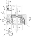
- FIGS. 1 to 4 braking devices 6 according to the invention of a mobile working machine 1 are shown, for example an industrial truck.
- the same components are provided here with the same reference numerals.
- traction motors 4a, 4b are arranged for driving drive wheels not shown in detail.
- the traction motors 4a, 4b are formed in the illustrated embodiment as electric motors.
- a traction battery can be provided, so that the working machine has a battery-electric drive system.
- an electric generator driven by an internal combustion engine may be provided for the power supply of the traction motors 4a, 4b, so that the working machine has an internal combustion engine-electric drive system.
- Output shafts 5a, 5b which are in operative connection with the traction motors 4a, 4b are in operative connection with a brake device 6 by means of which the output shafts 5a, 5b can be braked and locked.
- the braking device 6 is designed as a hydraulically releasable spring brake 7.
- the spring brake is designed as a multi-disc brake, preferably wet-running multi-disc brake, with alternately arranged on the output shafts 5a, 5b and on the axle housing 3 brake plates. 8
- the spring brake 7 is acted upon by a spring device 10 in a closed position forming the braking position.
- the spring brake 7 has for actuation between the braking position and a release position on a brake piston device 11, on which the spring device 10 is supported with a first end.
- the brake piston device 11 may be formed by a single piston or a plurality of pistons.
- the spring device 10 is supported at a second end on a stop 14 which is fixed to the axle housing 3.
- a brake release pressure chamber 12 is formed, wherein at a pending in the brake release pressure chamber 12 hydraulic brake release pressure, the spring brake 7 against the force of the spring device 10 can be acted upon in the direction of a release position.
- a brake pressure chamber 13 acting in the same direction as the spring device 10 is formed, wherein the spring brake 7 can be acted upon in the direction of the braking position when the hydraulic brake pressure is applied in the brake pressure chamber 13,
- the spring brake 7 according to the invention is designed as a dual-circuit service brake with a first brake circuit 15 and a second brake circuit 16.
- the first brake circuit 15 of the service brake is designed as a muscle-strength brake 20.
- the muscle-power brake system 20 has a manually operable brake cylinder 21, by means of which, in a manual actuation, a brake pressure which is present in the brake pressure chamber 13 can be generated.
- the brake cylinder 21 can be actuated by a driver by means of a brake pedal 17.
- the brake cylinder 21 is connected by means of a brake pressure leading brake pressure line 22 to the brake pressure chamber 13 of the spring brake 7 in conjunction.
- the first brake circuit 15 further comprises a surge tank 23 which is connected to the brake pressure line 22 or to a pressure chamber of the brake cylinder 21.
- the second brake circuit 16 of the service brake is designed as a power brake.
- the power brake has to control the spring brake 7 between the braking position and the release position, a pressure control valve 25.
- the pressure control valve 25 is connected to a pressure supply line 26 of a pressure supply device 27, to a guided to the brake release pressure chamber 12 of the spring brake 7 brake release pressure line 28 and to a container 29.
- the pressure supply device 27 is formed in the illustrated embodiments of a pressure fluid reservoir. Alternatively or additionally, the pressure supply device 27 may comprise a hydraulic pump. In the Pressure supply line 26 is arranged in the illustrated embodiments, in the direction of the pressure control valve 25 opening check valve 24.
- the pressure control valve 25 is in the present embodiments of the FIGS. 1 to 4 formed as a pressure control valve, for example, proportional pressure control valve with a falling characteristic.
- the pressure control valve 25 is in the non-actuated state in a release position in which the brake release pressure line 28 is in communication with the pressure supply line 26 and the connection of the brake release pressure line 28 is shut off to the container 29, so that in the brake release pressure chamber 12 of the spring device 10 counteracting brake release pressure is generated and the spring brake 7 is acted upon in the release position.
- the pressure control valve 25 When actuated by an actuator 31, the pressure control valve 25 is increasingly acted upon in a Bremslierebuch 28 connecting the container 29 braking position, so that dosed by a metered reduction in the brake release pressure line 28 brake release pressure the spring brake 7 to achieve a service brake function applied to the braking position becomes.
- the pressure control valve 25 is acted upon by means of a control line 30, which communicates with the brake release pressure line 28, of the pending in the brake release pressure line 28 brake release pressure against the actuator 31 and thus in the direction of the release position.
- first brake circuit 15 of the service brake can be generated and constructed by operating the brake pedal 17 in the brake pressure chamber 13, a brake pressure, which actuates the spring brake 7 in the braking position.
- second brake circuit 16 of the service brake can be controlled by dosed action of the pressure control valve 25 in the direction of the braking position in the brake release pressure chamber 12 pending brake release pressure and thus the spring brake 7 are actuated in the braking position.
- a pressure relief valve 35 is connected, which is the output side with the container 29 in connection.
- the actuating device 31 is for this purpose designed as an electrical actuating device, for example as a proportional magnet.
- the actuating device 31 can be connected to an electronic control device 40.
- the control device 40 is operatively connected to a control element 41 that can be operated by the driver, for example an accelerator pedal or an actuating lever, in response to the actuation of which the pressure regulating valve 25 is actuated into the braking position.
- the actuator 31 is designed as a plunger, which is operated for actuation with a not shown, operable by the driver control element, such as a hand brake lever or a pedal, in operative connection, in response to the actuation of the pressure control valve 25 in the braking position.
- the braking device 1 of FIGS. 1 to 4 is also used as a parking brake, by means of which the stationary machine can be locked at a standstill.
- an electrically actuated uncoupling valve 45 FIGS. 1 . 3 and 4
- an electrically actuatable switching valve 46 FIGG. FIGS. 1 and 4
- a manually operable parking brake function and / or an automatic parking brake function can be achieved.
- the uncoupling valve 45 is designed as a switching valve, which has an effective in the de-energized state blocking position 45a and an electrically switchable flow position 45b.
- the Abkoppelventil 45 is acted upon by a spring 47 in the blocking position 45a and actuated by an electrical actuator 48, such as a solenoid in the flow position 45b.
- the Abkoppelventil 45 is for electronic control in a manner not shown with the electronic control device 40 in connection.
- the blocking position 45a can preferably be formed as a seat valve.
- the switching valve 46 has a blocking position 46a and a depressurized position 46b and is arranged in a brake line connecting the brake release pressure line 28 to the container 29.
- the switching valve 46 is acted upon by a spring 51 in the blocking position 45a and acted upon by an electrical actuator 52, such as a solenoid, in the pressure release position 46b.
- the switching valve 46 is thus in the de-energized state in the blocking position 46a.
- the blocking position 46a can preferably be formed as a seat valve.
- the switching valve 46 When activated, the switching valve 46 is actuated in the pressure relief position 46b formed as a flow position, in which the brake release pressure chamber 12 is connected via the control line 50 directly and without the interposition of further valve devices with the container 29 to the parking brake function by reducing the brake release pressure in the brake release pressure chamber 12 to achieve.
- the switching valve 46 and the Abkoppelventil 45 are actuated by means of the electronic control device 40.
- a control element for the manual parking brake function can be operated by the operator control element 42 may be provided, for example, a switch or a handbrake lever, based on which the control device 40, the switching valve 46 and the uncoupling valve 45 energized.
- the automatic parking brake function is initiated by the control device 40, for example when the vehicle is at a standstill or after an operator leaves a driver's seat, for which purpose suitable sensors not shown in detail may be provided for detecting these operating states.
- a pressure sensor 66 is provided, which is in operative connection with the electronic control device 40 and detects the pressure in the brake release pressure chamber 12.
- the pressure sensor 66 it is possible with the pressure sensor 66 to control the pressure in the brake release pressure chamber 12 by corresponding control of the pressure control valve 25 and to regulate.
- the pressure sensor 66 is used in the FIGS. 1 to 4 detect the engagement of the parking brake and monitor the parking brake function.
- the manually operable pressure control valve 25 is locked after a corresponding actuation in the braking position by means of a locking device 65 in the braking position in which the brake release pressure in the brake release pressure chamber 12 is relieved to the container 29 and the spring brake 7 of the spring device 10 in the brake position is actuated.
- the braking device 1 of FIGS. 1 . 3 and 4 a further electrically actuated switching valve 55 with a blocking position 55a and a flow position 55b, which is associated with the brake release pressure chamber 12 and in a brake release pressure line 28 to the container 29 connecting control line 56 is arranged.
- the switching valve 55 is acted upon by a spring 57 in the flow position 55b and acted upon by an electrical actuator 58, such as a solenoid, in the blocking position 55a.
- the blocking position 55a may preferably be formed as a seat valve.
- the switching valve 55 is thus in the de-energized state in the flow position 55b and is acted upon by a control in the blocking position 55a.
- a pressure reduction device 59 is arranged in the control line 56 downstream of the switching valve 55.
- the pressure reduction device 59 is in the illustrated embodiment as a pressure relief valve, for example, pressure relief valve formed. However, the pressure reduction device 59 may also be formed by a diaphragm, a throttle, a pressure reducing valve, a throttle valve or a pressure accumulator.
- the switching valve 55 is actuated by means of the electronic control device 40.
- a manually operable hand pump 61 In order to tow a stationary machine in the de-energized state, is in the embodiments of the FIGS. 1 . 3 and 4 arranged in a container 29 to the brake release pressure line 28 connecting line 60, a manually operable hand pump 61.
- the switching valve 55 To release the spring brake 7 by means of the hand pump 61, the switching valve 55 is provided with a mechanical actuator 62 to manually actuate the switching valve 55 in de-energized machine in the locked position 55a and by pressing the hand pump 61 a To generate brake release pressure for releasing the spring brake 7 in the brake release pressure chamber 12.
- the braking device 1 of the invention FIGS. 1 to 4 works as follows.
- the spring brake 7 is to be operated in the release position. That in the FIGS. 1 . 3 and 4 existing Abkoppelventil 45 is actuated for this purpose in the flow position 45a.
- pressure control valve 25 of FIGS. 1 to 4 is thus generated by the pressure supply device 27, a brake release pressure in the brake release pressure line 28 and thus in the brake release pressure chamber 12 which actuates the brake piston device 11 against the force of the spring device 10 in a release position in which the spring brake 7 is released.
- the displaced by the movement of the brake piston device 11 from the brake pressure chamber 13 pressure fluid, such as hydraulic oil or brake fluid is conveyed into the surge tank 23 of the first brake circuit 15.
- the switching valve 55 of FIGS. 1 . 3 and 4 controlled and actuated by the actuator 58 in the blocking position 55a to prevent degradation of the brake release pressure in the brake release pressure chamber 12 to the container 29.
- the switching valve 46 is still not activated and is in the blocking position 46 a, to prevent degradation of the brake release pressure in the brake release pressure chamber 12 to the container 29.
- the braking device 1 further enables a manual and / or an automatic parking brake function.
- the manual parking brake function may be performed by the driver during a ride or when the vehicle is stationary.
- the automatic parking brake function is initiated automatically by the electronic control device 40, for example when the vehicle is at a standstill or after leaving the driver's seat by the operator.
- the electronic control device 40 actuates the switching valve 46 into the depressurized position 46b, in which the brake release pressure chamber 12 is connected to the reservoir 29 and thus the brake release pressure in the brake release pressure chamber 12 is relieved into the reservoir 29.
- the uncoupling valve 45 is further actuated in the blocking position 45a in order to prevent that via the pressure control valve 25 in the brake release pressure line 28, a brake release pressure from the pressure supply device 27 can be established.
- the brake piston device 11 By relieving the brake release pressure chamber 12 to the container in the FIGS. 1 to 4 the brake piston device 11 is actuated by the spring device 10 in the braking position of the spring brake 7. In which by the movement of the brake piston 11 enlarging brake pressure chamber 13 pressure fluid from the surge tank 23 of the first brake circuit 15 is sucked.
- the working machine can be actively braked by means of the service brake FIGS. 1 to 4 the two brake circuits 15 and 16 are available.
- a brake pressure is built up via the brake cylinder 21 and the brake pressure line 22 in the brake pressure chamber 13 and pushed into the brake pressure chamber 13 pressure fluid, so that the brake piston device 11 is actuated with the support of the spring device 10 in the braking position.
- the brake release pressure chamber 12 is reduced, the pressure medium pushed out of the brake release pressure chamber 12 being conveyed via the pressure regulating valve 25 of the second brake circuit 16 and its connection to the container 29 into the container 29.
- the brake torque generated by the spring brake 7 is dependent on the strength of the operation of the brake pedal 17. The more pressure is removed via the brake pedal 17, the more braking torque is generated at the spring brake 7. Due to the increase in pressure of the brake pressure in the brake pressure chamber 13, the driver receives a force feedback to the brake pedal 17 when the brake pedal 17 is actuated, so that the driver can easily meter the deceleration of the work machine.
- the pressure control valve 25 of the second brake circuit 16 Upon actuation of the pressure control valve 25 of the second brake circuit 16 in the direction of the braking position can be dosed by appropriate actuation by means of the actuator 31 in the brake release pressure chamber 12 pending brake release pressure and controlled to be reduced to the pressure level of the container 29, so that an auxiliary brake function used as a service brake Spring brake 7 is achieved.
- the pressure control valve 25 is electrically controlled accordingly by the electronic control device 40.
- the signal for the activation of the service brake by means of the second brake circuit 16 is generated by operation of the operating element 41, for example an accelerator pedal or an actuating lever, by the driver.
- the electronic control device 40 can control the pressure control valve 25 automatically for a service braking, for example in the context of an assistance system.
- the control of the pressure control valve 25 is carried out manually by the driver by an actuation of the operatively connected to the actuator 31 control element, such as a handbrake lever or a pedal.
- the brake piston device 11 is actuated by the spring device 10 in the braking position, wherein a braking torque of the spring brake 7 is built up in response to the regulated by means of the pressure control valve 25 in the brake release pressure chamber 12 brake release pressure.
- the brake pedal 17 can be actuated so that in the brake release pressure chamber 13, a brake pressure is generated and the machine is slowed down more.
- the brake release pressure in the brake release pressure chamber 12 can be controlled and metered reduced to allow a service brake of the machine by means of the spring brake 7, which is actuated by the spring device 10 in the braking position.
- the pressure control valve 25 thus the braking torque of the spring brake 7 can be dosed.
- the FIG. 1 can be dosed by appropriate electrical control of the electrically actuated pressure control valve 25, the braking torque of the service brake.
- the second brake circuit 16 fails, for example, as a result of a defect or failure of the pressure control valve 25, by pressing the brake pedal 17 of the first brake circuit 15 in the brake pressure chamber 13, a brake pressure and thus a braking torque of the spring brake 7 can be generated.
- the pressure medium from the decreasing brake release pressure chamber 12 is in this case discharged via the opening pressure relief valve 35 of the second brake circuit in the container 29.
- the pressure relief valve 35 is in this case designed and adjusted to such an opening pressure that the pressure relief valve 35 only above the maximum brake release pressure, which is generated and regulated by means of the pressure control valve 25, opens and at maximum allowable actuation force to the brake pedal 17th a minimum delay of the work machine is achieved in accordance with the requirements of the traffic regulations for the work machine.
- an emergency braking of the moving machine with a reduced braking torque can be achieved, for example, in the event of a power failure, an energy-free work machine or the operation of an emergency stop switch.
- the reduced braking torque is selected such that, during braking, load shedding of a load received by a load receiving means is avoided.
- the de-energized or energized state are in the FIGS. 1 and 4 in each case the uncoupling valve 45 and the switching valve 46 in the corresponding blocking positions 45a, 46a.
- the switching valve 55 is acted upon in the de-energized state in the flow position 55b in which the pending in the brake release pressure line 28 brake release pressure on the pressure reduction device 59 is reduced to the container 29 and as a result, the machine is braked with a reduced braking torque to a standstill.
- the brake release pressure is switched to the pressure reduction device 59 designed, for example, as a pressure-limiting valve.
- the pressure relief valve can flow as much pressure medium into the container 29 until the brake release pressure has fallen in the brake release pressure chamber 12 to the opening pressure of the pressure relief valve and corresponds to the opening pressure of the pressure relief valve.
- the brake piston device 11 is thus actuated by the spring device 10 as a function of the brake release pressure still present in the brake release pressure chamber 12 in the braking position.
- the from the movement of the brake piston device 11 magnifying brake pressure chamber 13 sucks pressure fluid from the surge tank 23 at.
- a pressure relief valve pressure reduction device 59 thus a defined brake release pressure can be adjusted, which generates a defined braking torque.
- FIGS. 1 to 4 is by the operation of the brake pedal 17 of the first brake circuit 15 in the emergency braking a deceleration possible to increase the Anlagenabbremsung and increase the delay of the working machine.
- the switching valve 55 can be manually operated by means of the actuator 62 in the blocking position 55a, so that by pressing the hand pump 61, a brake release pressure in the brake release pressure line 28 can be generated, with which the spring brake 7 is actuated in the release position.
- the work machine can be braked by means of the first brake circuit 15 by an operation of the brake pedal 17.
- the inventive, working as a service brake braking device 1 of FIGS. 1 to 4 has the advantage that the driver receives a force feedback to the brake pedal 17 of the first brake circuit 15 at the beginning of braking, so that overbraking of the working machine 1 can be effectively avoided and a good metering of the service brake by means of the first brake circuit 15 is made possible.
- the braking device 1 according to the invention has a low construction cost for the dual-circuit design of the service brake with the two brake circuits 15, 16.
- the brake device 1 according to the invention with the two brake circuits 15, 16 of the service brake allows a modular design.
- the embodiment of the FIG. 2 be created, which has a dual-circuit service brake and with the manually operated pressure control valve 25 is a manually operable auxiliary brake (second brake circuit 16 of the service brake) and a manually operable parking brake, for example by means of an actuation of the pressure control valve 25 by a cable.
- a variant is achievable, which in addition to a manually actuated auxiliary brake (second brake circuit 16 of the service brake) and a manually operable parking brake emergency braking with a reduced braking torque in case of failure allows.
- the switching valve 46 and the uncoupling 45 - as in the FIG.
- FIG. 4 is shown - can starting from the Figures 2 or 3 a variant with the function of an automatic parking brake can be achieved.
- FIG. 4 is thus a manually actuated auxiliary brake (second brake circuit 16 of the service brake) with a manual and / or automatically actuated parking brake (switching valve 46) combined.
- the pressure control valve 25 according to the FIG. 1 be electrically controlled, whereby the auxiliary service brake of the second brake circuit 16 of the service brake forms an electrically controllable power brake, which can be activated by the driver or automatically controlled by the electronic control device as part of an assistance function.
- the invention is not on the in the FIGS. 1 to 4 limited embodiments shown.
- the disconnection valve 45, the switching valve 46 and the further switching valve 55 may be combined in a control valve or in two control valves instead of the embodiment shown in the figures, in which these valves are each formed as a two-position two-port valve.
- the switching valve 46 and / or the switching valve 55 with the pressure reduction device 59 and the Abkoppelventil 45 may be omitted, provided that the function of an automatic parking brake and the function of emergency braking with a reduced braking torque are not required.
- two brake pistons may be used, of which a brake piston forms the brake pressure chamber 13 and the other brake piston forms the brake release pressure chamber 12.
- the invention is not limited to the illustrated embodiment, in which the braking device 6 brakes two output shafts 5a, 5b. It is understood that the braking device 6 can brake only one output shaft 5a or 5b, so that two brake devices 6 are present in a drive axle.
Landscapes
- Engineering & Computer Science (AREA)
- General Engineering & Computer Science (AREA)
- Mechanical Engineering (AREA)
- Physics & Mathematics (AREA)
- Electromagnetism (AREA)
- Transportation (AREA)
- Braking Systems And Boosters (AREA)
- Regulating Braking Force (AREA)
Abstract
Description
- Die Erfindung betrifft eine mobile Arbeitsmaschine, insbesondere Flurförderzeug, mit einer Bremseinrichtung, die als hydraulisch lösbare Federspeicherbremse und als zweikreisige Betriebsbremse ausgebildet ist, wobei die Federspeicherbremse mittels eines in einem Bremslösedruckraum anstehenden hydraulischen Bremslösedrucks in Richtung einer Lösestellung beaufschlagbar ist und mittels eines in einem Bremsdruckraum anstehenden hydraulischen Bremsdruckes in Richtung einer Bremsstellung beaufschlagbar ist.
- Bei mobilen Arbeitsmaschinen, beispielsweise als Gabelstaplern ausgebildeten Flurförderzeugen, werden hydraulisch lösbare Federspeicherbremsen als Bremseinrichtungen eingesetzt.
- Derartige als Federspeicherbremsen ausgebildete Bremseinrichtungen, die durch einen Bremslösedruck in einem Bremslösedruckraum entgegen der Federkraft einer Federeinrichtung in die Lösestellung beaufschlagbar und somit lüftbar sind, werden auch als hydraulisch beaufschlagte negative Federspeicherbremsen bezeichnet. Die Beaufschlagung der Federspeicherbremse in Richtung der Bremsstellung erfolgt durch einen Abbau des in dem Bremslösedruckraum anstehenden und von einem Bremsventil gesteuerten Bremslösedruckes, wobei die maximale Bremskraft und somit das maximale Bremsmoment durch die Federkraft der Federeinrichtung der Federspeicherbremse vorgegeben wird. Derartige Federspeicherbremsen, die lediglich durch Veränderung des in dem Bremslösedruckraum anstehenden Bremslösedrucks durch entsprechende Betätigung eines den Bremslösedruck steuerbaren Bremsventils zwischen der Lösestellung und der Bremsstellung betätigbar sind, werden auch als einkreisige Federspeicherbremsen bezeichnet.
- Eine alternative bekannte Ausführungsform von Bremseinrichtungen wird mechanisch und manuell, z.B. über einen Seilzug betätigt. In diesem Fall besteht keine Federvorspannung und die Bremseinrichtung muss aktiv in die Bremsstellung betätigt werden. Im unbetätigten Zustand befindet sich somit eine über einen Seilzug betätigte Bremseinrichtung in der Lösestellung, so dass die Arbeitsmaschine rollen kann. Ein bekannter Nachteil von über einen Seilzug betätigten Bremsen ist deren Neigung zum Längen. Durch diese Dehnung des Seilzugs treten starke Toleranzen auf, wodurch es auftreten kann, dass der Fahrer bei der Betätigung eines mit dem Seilzug in Wirkverbindung stehenden Bremspedals zuerst ein zu geringes Bremsmoment aufbaut und mit der folgenden Reaktion der Arbeitsmaschine durch weitere Betätigung des Bremspedals die Arbeitsmaschine überbremst. Zudem ergibt sich hierdurch ein hoher Wartungsaufwand, um den Seilzug bei einem Längen entsprechend nachzustellen.
- Eine Ausführungsform einer Federspeicherbremse ist eine Lamellenbremse, bei der ein Paket aus mehreren scheibenartigen Lamellen jeweils abwechselnd eine feststehende Lamelle und eine sich drehende Lamelle aufweist. Beim Bremsen wird dieses Paket über feststehende Lamellen an den Enden zusammengepresst und über die gesamte reibende Fläche eine mit den sich drehenden Lamellen verbundene Welle abgebremst. Eine Ausführungsform solcher Lamellenbremsen ist nasslaufend und dadurch wartungsfrei. Weitere Ausführungsformen der Bremseinrichtung, die bei älteren mobilen Arbeitsmaschinen eingesetzt wurden, sind beispielsweise Außenbacken-, Trommel- oder trocken laufende Vollscheibenbremsen.
- Derartige als einkreisige Federspeicherbremsen ausgebildete Bremseinrichtungen werden als Betriebsbremse und/oder Feststellbremse verwendet. Für die Betriebsbremse, mit der ein Abbremsen der fahrenden Arbeitsmaschine erfolgt, ist es erforderlich, dass die Federspeicherbremse abhängig von der Betätigung durch den Fahrer dosiert einsetzbar ist. Hierzu steht das Bremsventil mechanisch mit einem von der Bedienperson zu betätigenden Bedienelement, beispielsweise einem Bremspedal, in Verbindung, bei dessen Betätigung das Bremsventil mechanisch betätigt wird und dosiert betätigt werden kann, wodurch der im Bremslösedruckraum der Federspeicherbremse anstehenden Bremslösedruck dosiert und steuerbar abgebaut und somit die Federspeicherbremse als Betriebsbremse dosiert in die Bremsstellung betätigt werden kann.
- Nachteilig an derartigen als Betriebsbremsen eingesetzten hydraulisch lösbaren Federspeicherbremsen ist, dass - insbesondere bei federvorgespannten Lamellenbremsen - der Fahrer keine Rückmeldung an dem Bremspedal erhält, ab welchem Zeitpunkt die Bremse, etwa die Lamellen bei einer Lamellenbremse, anliegen, und somit keine Rückmeldung an dem Bremspedal über den Bremsbeginn erhält, da die Bremseinrichtung eine Fremdkraftbremse darstellt und durch den Fahrer über die Betätigung des Bremsventils nur der Druckabbau des Bremslösedruckes gesteuert wird. Der eigentliche Bremsdruck wird durch die Federkraft der Federeinrichtung der Federspeicherbremse erzeugt und führt nicht bei dem Fahrer zu einer Kraftrückmeldung bei Betätigung des Bremspedals. Durch die fehlende Rückmeldung an dem Bremspedal kann es zu einem Überbremsen der Arbeitsmaschine kommen. Bei einem Flurförderzeug kann ein Überbremsen zu einem Lastabwurf führen, wenn beispielsweise ein Gabelstapler als Flurförderzeug mit einer aufgenommenen Last so stark abgebremst wird, dass die Last von dem Lastaufnahmemittel, beispielsweise Lastgabeln, abgleitet.
- Eine Feststellbremse ist durch den Abbau des Bremslösedruckes in dem Bremslösedruckraum zu einem Behälter erzielbar, so dass die Federspeicherbremse durch die Federeinrichtung in die Bremsstellung betätigt wird.
- Für einen möglichen Betrieb der Arbeitsmaschine im öffentlichen Straßenverkehr ist entsprechend den Zulassungsvorschriften ein zweikreisiges Bremssystem der Betriebsbremse erforderlich, so dass bei Ausfall des ersten Bremskreises der zweite Bremskreis hiervon unabhängig noch funktioniert, oder alternativ ein einkreisiges Bremssystem erforderlich, das zwei voneinander unabhängig betätigbare und dosierbare Betätigungselemente aufweist.
- Hierzu ist es bekannt, die Federspeicherbremse zweikreisig auszuführen, wobei zusätzlich zu der Betriebsbremse durch die Betätigung des den Bremslösedruck steuernden Bremsventils eine Hilfsbremsfunktion vorgesehen ist, um bei einem Ausfall oder Defekt des Bremsventils über die Hilfsbremsfunktion die Arbeitsmaschine kontrolliert abbremsen zu können. Bei derartigen zweikreisigen Federspeicherbremsen ist es bekannt, an der Federspeicherbremse zusätzlich zu dem der Federeinrichtung entgegenwirkenden Bremslösedruckraum einen gleichsinnig mit der Federeinrichtung wirkenden Bremsdruckraum vorzusehen, wobei ein in dem Bremsdruckraum anstehender Bremsdruck von einem weiteren Bremsventil erzeugt wird, das von einem Bedienelement, beispielsweise dem Bremspedal, mechanisch betätigt wird. Das dem Bremsdruckraum zugeordnete Bremsventil erzeugt mit zunehmender Betätigung des Bremspedals einen in dem Bremsdruckraum ansteigenden Bremsdruck, der dem Bremslösedruck entgegenwirkt und somit die Federspeicherbremse in die Bremsstellung betätigt. Dadurch dass die beiden Bremsventile auf unterschiedliche Druckkammern der Federspeicherbremse wirken, wird somit die Zweikreisigkeit und die Hilfsbremsfunktion für die Betriebsbremse erzielt, so dass bei dem Ausfall oder Defekt eines Bremsventils jeweils über das andere Bremsventils die Arbeitsmaschine dosiert abgebremst werden kann. Das weitere Bremsventil bildet jedoch ebenfalls eine Fremdkraftbremse, bei der von dem Fahrer über die Betätigung des weiteren Bremsventils nur der Druckaufbau des Bremsdruckes gesteuert wird, so dass derartige zweikreisige Betriebsbremsen keine Kraftrückmeldung an dem Bremspedal aufweisen. Zudem weisen derartige als zweikreisige Betriebsbremse arbeitende Federspeicherbremsen aufgrund der beiden Bremsventile einen hohen Bauaufwand und hohe Herstellkosten auf.
- Eine Federspeicherbremse, die als zweikreisige Betriebsbremse arbeitet und zwei mittels eines Bremspedals steuerbare Bremsventile zur Steuerung des Bremslösedruckes in dem Bremslösedruckraums sowie des Bremsdruckes in einem entgegenwirkenden Bremsdruckraum aufweist, ist aus der
DE 10 2009 031 743 A1 bekannt. - Der vorliegenden Erfindung liegt die Aufgabe zugrunde, eine Bremseinrichtung der eingangs genannten Gattung zur Verfügung zu stellen, die bei geringem Bauaufwand eine zweikreisige Betriebsbremse ermöglicht und dem Fahrer eine Kraftrückmeldung im Betrieb als Betriebsbremse bietet.
- Diese Aufgabe wird erfindungsgemäß dadurch gelöst, dass ein erster Bremskreis der Betriebsbremse von einer Muskelkraftbremse gebildet ist, die einen manuell betätigbaren Bremszylinder aufweist, mittels dem bei einer manuellen Betätigung der in dem Bremsdruckraum anstehende Bremsduck erzeugbar ist, und ein zweiter Bremskreis der Betriebsbremse von einer Fremdkraftbremse gebildet ist, die ein Druckregelventil aufweist, mittels dem der in dem Bremslösedruckraum anstehende Bremslösedruck dosiert verringerbar ist. Die erfindungsgemäße, als Federspeicherbremse ausgebildete Bremseinrichtung ermöglicht somit eine zweikreisige Betriebsbremse, wobei der erste, als Muskelkraftbremse ausgebildete Bremskreis der Betriebsbremse eine Kraftrückmeldung an den Fahrer ermöglicht. Durch die Ausführung des ersten Bremskreises als Muskelkraftbremse weist die erfindungsgemäße Bremseinrichtung weiterhin einen geringen Bauaufwand auf, da eine Muskelkraftbremse einen einfachen und kostengünstigen Aufbau ohne aufwändiges Bremsventil erfordert. Sofern im Normalfall mit dem ersten Bremskreis abgebremst wird und der zweite Bremskreis die Hilfsbremse der Betriebsbremse darstellt, wird somit bei geringem Bauaufwand bei einer hydraulisch lösbaren Federspeicherbremse eine zweikreisige Betriebsbremse zur Verfügung gestellt, die über die Ausführung des ersten Bremskreises als Muskelkraftbremse dem Fahrer eine Kraftrückmeldung im Betrieb als Betriebsbremse bietet.
- Gemäß einer Ausführungsform der Erfindung ist der Bremszylinder des ersten Bremskreises von einem Bremspedal betätigt und steht mittels einer Bremsdruckleitung mit dem Bremsdruckraum der Federspeicherbremse in Verbindung, wobei der erste Bremskreis einen Ausgleichsbehälter aufweist. Mit einem von einem Bremspedal betätigten Bremszylinder, der mittels einer Bremsdruckleitung mit dem Bremsdruckraum der Federspeicherbremse in Verbindung steht, kann mit geringem Bauaufwand eine Muskelkraftbremse zur Verfügung gestellt werden. Der Ausgleichsbehälter ermöglicht es auf einfache Weise, dass beim Abbremsen mittels des zweiten Bremskreises Druckmittel aus dem Ausgleichsbehälter in den Bremsdruckraum strömen bzw. zum Lösen der Federspeicherbremse Druckmittel aus dem Bremsdruckraum in den Ausgleichsbehälter strömen kann.
- Besondere Vorteile ergeben sich, wenn gemäß einer Ausführungsform der Erfindung das Druckregelventil als Proportional-Druckregelventil ausgebildet ist, insbesondere als Proportional-Druckregelventil mit einer fallenden Ventilkennlinie. Ein derartiges Proportional-Druckregelventil ermöglicht mit einem geringen Zusatzaufwand die Hilfsbremsfunktion der Betriebsbremse. Hierbei kann ein Proportional-Druckregelventil mit einer fallenden Ventilkennlinie eingesetzt werden, das im nicht betätigten Zustand den Bremslösedruck erzeugt und mit zunehmender Betätigung den Bremslösedruck verringert. Mit zunehmender Betätigung des Druckregelventils kann somit der von dem Druckregelventil gesteuerte Bremslösedruck dosiert und gesteuert verringert werden, um die Federspeicherbremse dosierbar in die Bremsstellung zu betätigen und die Hilfsbremsfunktion der Betriebsbremse zu erzielen.
- Gemäß einer vorteilhaften Ausführungsform der Erfindung ist das Druckregelventil an eine Druckversorgungsleitung einer Druckversorgungseinrichtung, an eine zu dem Bremslösedruckraum der Federspeicherbremse geführte Bremslösedruckleitung und an einen Behälter angeschlossen. Mit einem derartigen Druckregelventil kann auf einfache Weise durch Verbindung der Druckversorgungsleitung mit der Bremslösedruckleitung die Federspeicherbremse in die Lösestellung und durch Verbinden der Bremslösedruckleitung mit dem Behälter die Federspeicherbremse in die Bremsstellung betätigt werden.
- Gemäß einer vorteilhaften Ausführungsform der Erfindung ist das Druckregelventil manuell betätigbar. Hierdurch ist eine kostengünstige Ausführung der Bremseinrichtung und des zweiten Bremskreises und somit der Hilfsbremse der Betriebsbremse erzielbar. Das Druckregelventil kann hierzu mit einem Pedal oder einem Handbremshebel zur Betätigung in Wirkverbindung stehen.
- Gemäß einer vorteilhaften Weiterbildung der Erfindung ist die Federspeicherbremse als Feststellbremse ausgebildet, wobei das manuell betätigbare Druckregelventil mit einer Arretiereinrichtung versehen ist, mittels der das Druckregelventil in einem betätigten Zustand, in dem der Bremslösedruck abgebaut ist, arretierbar ist. Das für die Hilfsbremse der Betriebsbremse vorhandene Druckregelventil kann auch für die weitere Funktion einer Feststellbremse der Federspeicherbremse verwendet werden, mit der die Arbeitsmaschine im Stillstand festgesetzt werden kann. Bei der Ausführung des Druckregelventils als manuell betätigbares Druckregelventil ist die Feststellbremsfunktion auf einfache Weise erzielbar, wenn sich das Druckregelventil mittels einer Arretiereinrichtung in der betätigten Endstellung arretieren lässt, in der die Bremslösedruckleitung mit dem Behälter verbunden ist und somit der Bremslösedruck zum Behälter abgebaut ist.
- Gemäß einer alternativen und vorteilhaften Ausführungsform der Erfindung ist das Druckregelventil elektrisch betätigbar. Mit einem elektrisch betätigbaren Druckregelventil, das zur Betätigung beispielsweise mit einer elektronischen Steuereinrichtung in Wirkverbindung steht, kann der zweite Bremskreises und somit die Hilfsbremse der Betriebsbremse in Abhängigkeit von der Betätigung eines Bedienelements, beispielsweise einer Fahrpedaleinrichtung oder eines Bremspedals, erfolgen, die von der elektronischen Steuereinrichtung erfassbar ist. Zudem ermöglicht es ein elektrisch betätigbares Druckregelventil, den zweiten Bremskreis und somit die Hilfsbremse der Betriebsbremse automatisiert von der elektronischen Steuereinrichtung anzusteuern, so dass eine Assistenzfunktion erzielt wird, mit der die Hilfsbremse automatisiert betätigt wird, sofern ein Defekt im ersten Bremskreis auftritt.
- Gemäß einer vorteilhaften Weiterbildung der Erfindung ist der Bremslösedruckraum an ein Druckbegrenzungsventil angeschlossen. Ein derartiges, an den Bremslösedruckraum und somit die Bremslösedruckleitung angeschlossenes Druckbegrenzungsventil ermöglicht es auf einfache Weise, dass bei einem Ausfall des Druckregelventils und somit einem Ausfall des zweiten Bremskreises mit dem ersten Bremskreis die Arbeitsmaschine abgebremst werden kann, wobei das aus dem Bremslösedruckraum ausgeschobene Druckmittel über das Druckbegrenzungsventil auf einfache Weise zu einem Behälter abgeführt werden kann.
- Zweckmäßigerweise ist hierbei der Öffnungsdruck des Druckbegrenzungsventils derart eingestellt, dass der Öffnungsdruck höher als der maximal mittels des Druckregelventils einstellbare Bremslösedruck ist. Hierdurch wird auf einfache Weise ermöglicht, dass bei einer maximal zulässigen Betätigungskraft an dem Bremspedal des ersten Bremskreises, die von dem Fahrer aufgebracht wird, mindestens eine Fahrzeugverzögerung erzielbar ist, die einer für die Straßenverkehrszulassung der Arbeitsmaschine vorgeschriebenen Fahrzeugverzögerung entspricht.
- Gemäß einer vorteilhaften Weiterbildung der Erfindung ist die Federspeicherbremse als Feststellbremse ausgebildet, wobei in der zu dem Druckregelventil geführten Druckversorgungsleitung ein elektrisch betätigbares Abkoppelventil angeordnet ist und ein elektrisch betätigbares Schaltventil vorgesehen ist, das dem Bremslösedruckraum zugeordnet ist, wobei das Schaltventil eine im stromlosen Zustand wirksame Sperrstellung und eine elektrisch schaltbare, den Bremslösedruckraum mit einem Behälter verbindende Drucklosstellung aufweist, wobei zur Erzielung der Feststellbremse das Schaltventil in die Drucklosstellung bestromt ist und das Druckregelventil mittels des Abkoppelventils abgekoppelt ist. Bei der Ausführung des Druckregelventils als elektrisch oder manuell betätigbares Druckregelventil kann in Verbindung mit einem derartigen Abkoppelventil und einem derartigen Schaltventil auf einfache Weise die Federspeicherbremse als Feststellbremse betrieben werden. Eine derartige Feststellbremsfunktion ist hierbei auf einfache Weise erzielbar, wenn das Schaltventil durch eine elektrische Ansteuerung des Schaltventils in die Drucklosstellung beaufschlagt ist. Durch Ansteuern und Bestromen des Schaltventils und Abkoppeln des Druckregelventils kann ein sofortiger Druckabbau des in dem Bremslösedruckraum anstehenden Bremslösedruckes erzielt werden, so dass ein sofortiges Einfallen der Federspeicherbremse in die Bremsstellung erzielt werden kann. Durch die elektrische Betätigung des Abkoppelventils und des Schaltventils ist hierbei eine manuell betätigbare Feststellbremse und/oder eine automatische Feststellbremse auf einfache Weise erzielbar. Als manuell betätigbare Feststellbremse im Sinne der Erfindung soll eine von der Bedienperson durchführbare Betätigung der Federspeicherbremse in die Bremsstellung angesehen werden, die bei Fahrzeugstillstand oder während der Fahrt von der Bedienperson ausgelöst werden kann. Sofern das Abkoppelventil und das Schaltventil von einer elektronischen Steuereinrichtung betätigbar ist, die eingangsseitig mit einem entsprechenden, von dem Fahrer betätigbaren Bedienelement für die Feststellbremse in Verbindung steht, kann eine derartige manuell betätigbare Feststellbremse auf einfache Weise verwirklicht werden. Eine automatische Feststellbremse im Sinne der Erfindung bildet eine im Fahrzeugstillstand automatische Betätigung der Federspeicherbremse in die Bremsstellung. Mit der Funktion einer automatischen Feststellbremse, die im Fahrzeugstillstand von einer elektronischen Steuereinrichtung, die das Abkoppelventil und das Schaltventil ansteuert, automatisch eingeleitet wird, kann eine Fahrerunterstützung auf einfache Weise erzielt werden, indem beispielsweise bei einer stehenden Arbeitsmaschine oder einem Verlassen des Fahrerarbeitsplatzes die Federspeicherbremse automatisch in die Bremsstellung beaufschlagt wird.
- Gemäß einer alternativen und vorteilhaften Weiterbildung der Erfindung ist die Federspeicherbremse als Feststellbremse ausgebildet, wobei in der zu dem Druckregelventil geführten Druckversorgungsleitung ein elektrisch betätigbares Abkoppelventil angeordnet ist, wobei zur Erzielung der Feststellbremse das Druckregelventil mittels des Abkoppelventils abgekoppelt ist und durch Betätigung des Druckregelventils der Bremslösedruckraum zu dem Behälter entlastet ist.
Bei der Ausführung des Druckregelventils als elektrisch oder manuell betätigbares Druckregelventil kann in Verbindung mit einem derartigen Abkoppelventil und der Entlastung des Bremslösedruckraums zu dem Behälter durch entsprechende Betätigung des Druckregelventils auf einfache Weise die Federspeicherbremse als Feststellbremse betrieben werden. Eine derartige Feststellbremsfunktion ist hierbei auf einfache Weise erzielbar, wenn mittels des Abkoppelventils durch eine elektrische Ansteuerung des Abkoppelventils das Druckregelventil von der Druckversorgung abgekoppelt wird und der Bremslösedruckraum durch Ansteuerung des Druckregelventils zu dem Behälter entlastet wird, so dass ein Einfallen der Federspeicherbremse in die Bremsstellung erzielt wird. Hierdurch ist eine manuell betätigbare Feststellbremse und/oder eine automatische Feststellbremse auf einfache Weise erzielbar. - Bevorzugt ist das Abkoppelventil als Schaltventil ausgebildet, das eine im stromlosen Zustand wirksame Sperrstellung und eine elektrisch schaltbare Durchflussstellung aufweist. Mit einem derartigen Abkoppelventil wird auf einfache Weise in der Sperrstellung eine Abkopplung des Druckregelventils für die Verwendung der Federspeicherbremse als Feststellbremse erzielt und in der Durchflussstellung die Steuerung der als Betriebsbremse verwendeten Federspeicherbremse zwischen der Bremsstellung und der Lösestellung ermöglicht.
- Gemäß einer vorteilhaften Weiterbildung der Erfindung ermöglicht die Federspeicherbremse im stromlosen Zustand eine Notbremsung der Arbeitsmaschine mit einem reduzierten Bremsmoment, wobei ein weiteres elektrisch betätigbares Schaltventil vorgesehen ist, das dem Bremslösedruckraum zugeordnet ist, wobei das weitere Schaltventil eine im stromlosen Zustand wirksame Durchflussstellung aufweist, in der der Bremslösedruckraum über eine Druckabbaueinrichtung mit einem Behälter in Verbindung steht, und eine elektrisch schaltbare Sperrstellung aufweist, und das weitere Schaltventil zur Erzielung der Notbremsung unbestromt ist. Bei mobilen Arbeitsmaschinen ist eine Notbremsfunktion gewünscht, mit der die fahrende Arbeitsmaschine im Fehlerfall, beispielsweise einem Stromausfall, einem energielosen Zustand, oder bei einer Betätigung eines Not-Aus-Schalters mit einem reduzierten Bremsmoment abgebremst wird, um bei einem Flurförderzeug während der Notbremsung durch eine zu starke Verzögerung einen Abwurf einer aufgenommenen Last zu vermeiden. Mit einem weiteren Schaltventil, das im stromlosen Zustand den Bremslösedruckraum über eine Druckabbaueinrichtung mit dem Behälter verbindet, kann eine derartige Notbremsfunktion mit einem reduzierten Bremsmoment durch den an der Druckabbaueinrichtung erzielten Druckabbau des Bremslösedruckes auf einen definierten Wert oder einen zeitverzögerten Druckabbau des Bremslösedruckes auf einfache Weise erzielt werden.
- Gemäß einer vorteilhaften Weiterbildung der Erfindung ist das weitere Schaltventil mit einer manuellen Betätigungseinrichtung versehen, mittels der das weitere Schaltventil in die Sperrstellung betätigbar ist, oder ist die Druckabbaueinrichtung manuell im Einstelldruck verstellbar, und ist eine Handpumpe vorgesehen, mittels der in dem Bremslösedruckraum ein Bremslösedruck erzeugbar ist. Durch Betätigen des weiteren Schaltventils in die Sperrstellung bzw. Verstellen des Einstelldrucks der Druckabbaueinrichtung auf einen Druckwert oberhalb des Bremslösedruckes kann mit der Handpumpe auf einfache Weise ein Bremslösedruck zum Lösen der Federspeicherbremse erzeugt werden, um eine stehende Arbeitsmaschine im stromlosen Zustand abschleppen zu können.
- Gemäß einer vorteilhaften Ausführungsform der Erfindung weist die Bremseinrichtung einen modularen Aufbau auf, wobei zumindest zwei verschiedene Steuerventileinrichtungen vorgesehen sind, wobei eine erste Ausführungsform der Steuerventileinrichtung das Druckregelventil und das Druckbegrenzungsventil umfasst, und eine zweite Ausführungsform der Steuerventileinrichtung das Druckregelventil, das Druckbegrenzungsventil und mindestens eine der folgenden Komponenten umfasst:
- das Schaltventil und das Abkoppelventil,
- das weitere Schaltventil und die Druckabbaueinrichtung,
- die Handpumpe.
- Bei der erfindungsgemäßen Bremseinrichtung mit dem als Muskelkraftbremse ausgebildeten ersten Bremskreis der von der Federspeicherbremse gebildeten Betriebsbremse wird mit besonderem Vorteil ein modularer Aufbau erzielbar, der es mit unterschiedlichen Steuerventilen ermöglicht, über die Steuerung des Bremslösedrucks verschiedene Ausbaustufen der Bremseinrichtung herzustellen. Sofern eine erste Ausführungsform der Steuerventileinrichtung nur das Druckregelventil, beispielsweise ein manuell betätigbares Druckregelventil, und das Druckbegrenzungsventil aufweist, kann eine Basisausführung mit einer manuell betätigbaren Hilfsbremse und einer manuell betätigbaren Feststellbremse hergestellt werden. Durch weitere Ausführungsformen der Steuerventileinrichtung mit dem Schaltventil und dem Abkoppelventil kann eine Ausführungsform mit einer automatischen Feststellbremse erzeugt werden. Sofern eine weitere Ausführungsformen der Steuerventileinrichtung das weitere Schaltventil und die Druckabbaueinrichtung umfasst, kann die Bremseinrichtung um die Funktion der Notbremsung der Arbeitsmaschine mit einem reduzierten Bremsmoment erweitert werden.
- Bei der erfindungsgemäßen mobilen Arbeitsmaschine kann die Bremskolbeneinrichtung einen Bremskolben aufweisen, an dem sowohl der Bremsdruckraum als auch der Bremslösedruckraum ausgebildet ist. Alternativ kann die Bremskolbeneinrichtung einen ersten Bremskolben aufweisen, an dem der Bremsdruckraum ausgebildet ist, und zweiten Bremskolben aufweist, an dem Bremslösedruckraum ausgebildet ist,
- Besondere Vorteile ergeben sich, wenn gemäß einer Weiterbildung der Erfindung ein Drucksensor vorgesehen ist, der den in dem Bremslösedruckraum anstehenden Bremslösedruck erfasst. Mit einem derartigen Drucksensor kann in Verbindung mit einem elektrisch betätigbaren Druckregelventil durch entsprechende Ansteuerung des Druckregelventils eine Regelung des in dem Bremslösedruckraum anstehenden Bremslösedruckes erzielt werden. Weiterhin kann mit einem derartigen Drucksensor auf einfache Weise die Feststellbremsfunktion überwacht werden.
- Die Arbeitsmaschine weist gemäß einer vorteilhaften Ausführungsform der Erfindung ein batterie-elektrisches Antriebssystem, ein verbrennungsmotorisch-elektrisches Antriebssystem oder ein verbrennungsmotorisch-hydrodynamisches Antriebssystem auf.
- Weitere Vorteile und Einzelheiten der Erfindung werden anhand der in den schematischen Figuren dargestellten Ausführungsbeispiele näher erläutert. Hierbei zeigt
- Figur 1
- eine erste Ausführungsform einer mobilen Arbeitsmaschine mit einer erfindungsgemäßen Bremseinrichtung,
- Figur 2
- eine zweite Ausführungsform einer mobilen Arbeitsmaschine mit einer erfindungsgemäßen Bremseinrichtung,
- Figur 3
- eine dritte Ausführungsform einer mobilen Arbeitsmaschine mit einer erfindungsgemäßen Bremseinrichtung und
- Figur 4
- eine vierte Ausführungsform einer mobilen Arbeitsmaschine mit einer erfindungsgemäßen Bremseinrichtung.
- In den
Figuren 1 bis 4 sind erfindungsgemäße Bremseinrichtungen 6 einer mobilen Arbeitsmaschine 1 dargestellt, beispielsweise eines Flurförderzeugs. Gleiche Bauteile sind hierbei mit gleichen Bezugsziffern versehen. - Dargestellt ist ein Ausschnitt einer Antriebsachse 2 der Arbeitsmaschine mit einem Achsgehäuse 3, in dem Fahrmotoren 4a, 4b zum Antrieb nicht näher dargestellter Antriebsräder angeordnet sind. Die Fahrmotoren 4a, 4b sind im dargestellten Ausführungsbeispiel als Elektromotoren ausgebildet. Zur Stromversorgung der Fahrmotoren 4a, 4b kann eine Traktionsbatterie vorgesehen werden, so dass die Arbeitsmaschine ein batterie-elektrisches Antriebssystem aufweist. Alternativ kann zur Stromversorgung der Fahrmotoren 4a, 4b ein von einem Verbrennungsmotor angetriebener elektrischer Generator vorgesehen werden, so dass die Arbeitsmaschine ein verbrennungsmotorisch-elektrisches Antriebssystem aufweist.
- Mit den Fahrmotoren 4a, 4b in trieblicher Verbindung stehende Abtriebswellen 5a, 5b stehen mit einer Bremseinrichtung 6 in Wirkverbindung, mittels der die Abtriebswellen 5a, 5b abbremsbar und arretierbar sind. Die Bremseinrichtung 6 ist als hydraulisch lösbare Federspeicherbremse 7 ausgebildet. Im dargestellten Ausführungsbeispiel ist die Federspeicherbremse als Lamellenbremse, bevorzugt nasslaufende Lamellenbremse ausgebildet, mit abwechselnd an den Abtriebswellen 5a, 5b und an dem Achsgehäuse 3 angeordneten Bremslamellen 8.
- Die Federspeicherbremse 7 ist von einer Federeinrichtung 10 in eine die Bremsstellung bildende Schließstellung beaufschlagt. Die Federspeicherbremse 7 weist zur Betätigung zwischen der Bremsstellung und einer Lösestellung eine Bremskolbeneinrichtung 11 auf, an der die Federeinrichtung 10 mit einem ersten Ende abgestützt ist. Die Bremskolbeneinrichtung 11 kann von einem einzelnen Kolben oder mehreren Kolben gebildet sein. Die Federeinrichtung 10 ist an einem zweiten Ende an einem Anschlag 14 abgestützt, der an dem Achsgehäuse 3 befestigt ist. Zwischen dem Achsgehäuse 3 und der Bremskolbeneinrichtung 11 ist ein Bremslösedruckraum 12 ausgebildet, wobei bei einem in dem Bremslösedruckraum 12 anstehenden hydraulischen Bremslösedruck die Federspeicherbremse 7 entgegen der Kraft der Federeinrichtung 10 in Richtung einer Lösestellung beaufschlagbar ist. Zwischen dem Achsgehäuse 3 und der Bremskolbeneinrichtung 11 ist ein gleichsinnig zur Federeinrichtung 10 wirkender Bremsdruckraum 13 ausgebildet, wobei bei einem in dem Bremsdruckraum 13 anstehenden hydraulischen Bremsdruck die Federspeicherbremse 7 in Richtung der Bremsstellung beaufschlagbar ist,
- Die erfindungsgemäße Federspeicherbremse 7 ist als zweikreisige Betriebsbremse ausgebildet mit einem ersten Bremskreis 15 und einem zweiten Bremskreis 16.
- Der erste Bremskreis 15 der Betriebsbremse ist als Muskelkraftbremse 20 ausgebildet. Die Muskelkraftbremsanlage 20 weist einen manuell betätigbaren Bremszylinder 21 auf, mittels dem bei einer manuellen Betätigung ein in dem Bremsdruckraum 13 anstehender Bremsduck erzeugbar ist.
- Der Bremszylinder 21 ist von einem Fahrer mittels eines Bremspedals 17 betätigbar. Der Bremszylinder 21 steht mittels einer den erzeugten Bremsdruck führenden Bremsdruckleitung 22 mit dem Bremsdruckraum 13 der Federspeicherbremse 7 in Verbindung. Der erste Bremskreis 15 weist weiterhin einen Ausgleichsbehälter 23 auf, der an die Bremsdruckleitung 22 oder an einen Druckraum des Bremszylinders 21 angeschlossen ist. Von dem Fahrer wird somit durch Betätigen des Bremspedals 17 mittels des Bremszylinders 21 und eines gegebenenfalls vorhandenen Bremskraftverstärkers ein Bremsdruck in dem Bremsdruckraum 13 erzeugt, der die Federspeicherbremse 7 in die Bremsstellung betätigt.
- Der zweite Bremskreis 16 der Betriebsbremse ist als Fremdkraftbremse ausgebildet. Die Fremdkraftbremse weist zur Steuerung der Federspeicherbremse 7 zwischen der Bremsstellung und der Lösestellung ein Druckregelventil 25 auf. Das Druckregelventil 25 ist an eine Druckversorgungsleitung 26 einer Druckversorgungseinrichtung 27, an eine zu dem Bremslösedruckraum 12 der Federspeicherbremse 7 geführte Bremslösedruckleitung 28 und an einen Behälter 29 angeschlossen. Die Druckversorgungseinrichtung 27 ist in den dargestellten Ausführungsbeispielen von einem Druckmittelspeicher gebildet. Alternativ oder zusätzlich kann die Druckversorgungseinrichtung 27 eine Hydraulikpumpe umfassen. In der Druckversorgungsleitung 26 ist in den dargestellten Ausführungsbeispielen ein in Richtung zu dem Druckregelventil 25 öffnendes Rückschlagventil 24 angeordnet.
- Das Druckregelventil 25 ist in den vorliegenden Ausführungsbeispielen der
Figuren 1 bis 4 als Druckregelventil, beispielsweise Proportional-Druckregelventil mit einer fallenden Kennlinie ausgebildet. - Das Druckregelventil 25 befindet sich im nicht betätigten Zustand in einer Lösestellung, in der die Bremslösedruckleitung 28 mit der Druckversorgungsleitung 26 in Verbindung steht und die Verbindung der Bremslösedruckleitung 28 zum Behälter 29 abgesperrt ist, so dass im Bremslösedruckraum 12 ein der Federeinrichtung 10 entgegenwirkender Bremslösedruck erzeugt wird und die Federspeicherbremse 7 in die Lösestellung beaufschlagt wird.
- Bei einer Betätigung durch eine Betätigungseinrichtung 31 wird das Druckregelventil 25 zunehmend in eine die Bremslösedruckleitung 28 mit dem Behälter 29 verbindende Bremsstellung beaufschlagt, so dass durch einen dosierten Abbau des in der Bremslösedruckleitung 28 anstehenden Bremslösedruckes die Federspeicherbremse 7 zur Erzielung einer Betriebsbremsfunktion dosiert in die Bremsstellung beaufschlagt wird.
- Das Druckregelventil 25 ist mittels einer Steuerleitung 30, die mit der Bremslösedruckleitung 28 in Verbindung steht, von dem in der Bremslösedruckleitung 28 anstehenden Bremslösedruck entgegen der Betätigungseinrichtung 31 und somit in Richtung der Lösestellung beaufschlagt.
- Mit dem ersten Bremskreis 15 der Betriebsbremse kann durch Betätigen des Bremspedals 17 in dem Bremsdruckraum 13 ein Bremsdruck erzeugt und aufgebaut werden, der die Federspeicherbremse 7 in die Bremsstellung betätigt. Mit dem zweiten Bremskreis 16 der Betriebsbremse kann durch entsprechende Betätigung des Druckregelventils 25 in Richtung der Bremsstellung der in dem Bremslösedruckraum 12 anstehende Bremslösedruck gesteuert und dosiert abgebaut werden und somit die die Federspeicherbremse 7 in die Bremsstellung betätigt werden.
- An die Bremslösedruckleitung 28 ist ein Druckbegrenzungsventil 35 angeschlossen, das ausgangsseitig mit dem Behälter 29 in Verbindung steht.
- In dem Ausführungsbeispiel der
Figur 1 ist das Druckregelventil 25 elektrisch betätigbar. Die Betätigungseinrichtung 31 ist hierzu als elektrische Betätigungseinrichtung, beispielsweise als Proportionalmagnet, ausgebildet. Zur Ansteuerung kann die Betätigungseinrichtung 31 mit einer elektronischen Steuereinrichtung 40 in Verbindung stehen. Eingangsseitig steht die Steuereinrichtung 40 mit einem von dem Fahrer bedienbaren Bedienelement 41, beispielsweise einem Fahrpedal oder einem Betätigungshebel, in Wirkverbindung, in Abhängigkeit von dessen Betätigung das Druckregelventil 25 in die Bremsstellung betätigt wird. - In den
Figuren 2 bis 4 ist das Druckregelventil 25 manuell betätigbar. Die Betätigungseinrichtung 31 ist als Stößel ausgebildet, der zur Betätigung mit einem nicht näher dargestellten, von dem Fahrer bedienbaren Bedienelement, beispielsweise einem Handbremshebel oder einem Pedal, in Wirkverbindung, in Abhängigkeit von dessen Betätigung das Druckregelventil 25 in die Bremsstellung betätigt wird. - Die Bremseinrichtung 1 der
Figuren 1 bis 4 ist weiterhin als Feststellbremse einsetzbar, mittels der die stehende Arbeitsmaschine im Stillstand arretierbar ist. - Hierzu ist bei den Ausführungsbeispielen der
Figuren 1 ,3 und4 in der zu dem Druckregelventil 25 geführten Druckversorgungsleitung 26 ein elektrisch betätigbares Abkoppelventil 45 (Figuren 1 ,3 und4 ) angeordnet und ein elektrisch betätigbares Schaltventil 46 (Figuren 1 und4 ) vorgesehen, das dem Bremslösedruckraum 12 zugeordnet ist. Mit dem Abkoppelventil 45 und dem Schaltventil 46 kann eine manuell betätigbare Feststellbremsfunktion und/oder eine automatische Feststellbremsfunktion erzielt werden. - Das Abkoppelventil 45 ist als Schaltventil ausgebildet, das eine im stromlosen Zustand wirksame Sperrstellung 45a und eine elektrisch schaltbare Durchflussstellung 45b aufweist. Das Abkoppelventil 45 ist hierzu von einer Feder 47 in die Sperrstellung 45a beaufschlagt und durch eine elektrische Betätigungseinrichtung 48, beispielsweise einen Schaltmagneten, in die Durchflussstellung 45b betätigbar. Das Abkoppelventil 45 steht zur elektronischen Ansteuerung auf nicht näher dargestellte Weise mit der elektronischen Steuereinrichtung 40 in Verbindung. Die Sperrstellung 45a kann bevorzugt als Sitzventil ausgebildet werden.
- Das Schaltventil 46 weist eine Sperrstellung 46a und eine Drucklosstellung 46b auf und ist in einer die Bremslösedruckleitung 28 mit dem Behälter 29 verbindenden Steuerleitung 50 angeordnet. Das Schaltventil 46 ist von einer Feder 51 in die Sperrstellung 45a beaufschlagt und durch eine elektrische Betätigungseinrichtung 52, beispielsweise einen Schaltmagneten, in die Drucklosstellung 46b beaufschlagbar. Das Schaltventil 46 befindet sich somit im stromlosen Zustand in der Sperrstellung 46a. Die Sperrstellung 46a kann bevorzugt als Sitzventil ausgebildet werden. Bei einer Ansteuerung wird das Schaltventil 46 in die als Durchflussstellung ausgebildete Drucklosstellung 46b betätigt, in der der Bremslösedruckraum 12 über die Steuerleitung 50 direkt und ohne Zwischenschaltung weiterer Ventileinrichtungen mit dem Behälter 29 verbunden ist, um durch den Abbau des Bremslösedruckes in dem Bremslösedruckraum 12 die Feststellbremsfunktion zu erzielen.
- Das Schaltventil 46 und das Abkoppelventil 45 sind mittels der elektronischen Steuereinrichtung 40 betätigbar. Als Bedienelement für die manuelle Feststellbremsfunktion kann ein von dem Fahrer bedienbares Bedienelement 42 vorgesehen sein, beispielsweise ein Schalter oder ein Handbremshebel, anhand dessen die Steuereinrichtung 40 das Schaltventil 46 und das Abkoppelventil 45 bestromt.
- Die automatische Feststellbremsfunktion wird von der Steuereinrichtung 40 initiiert, beispielsweise im Fahrzeugstillstand oder nachdem eine Bedienperson einen Fahrersitz verlässt, wozu zum Erfassen dieser Betriebszustände geeignete nicht näher dargestellte Sensoren vorgesehen sein können.
- In den
Figuren 1 bis 4 ist weiterhin ein Drucksensor 66 vorgesehen, der mit der elektronischen Steuereinrichtung 40 in Wirkverbindung steht und den Druck in dem Bremslösedruckraum 12 erfasst. In derFigur 1 wird es mit dem Drucksensor 66 ermöglicht, den im Bremslösedruckraum 12 anstehenden Druck durch entsprechende Ansteuerung des Druckregelventils 25 zu steuern bzw. zu regeln. Weiterhin dient der Drucksensor 66 dazu, in denFiguren 1 bis 4 das Einfallen der Feststellbremse zu erfassen und die Feststellbremsfunktion zu überwachen. - Um in den Ausführungsbeispielen der
Figuren 2 und3 eine manuelle Feststellbremsfunktion zu erzielen, ist das manuell betätigbare Druckregelventil 25 nach einer entsprechenden Betätigung in die Bremsstellung mittels einer Arretiereinrichtung 65 in der Bremsstellung arretierbar, in der der Bremslösedruck in dem Bremslösedruckraum 12 zum Behälter 29 entlastet ist und die Federspeicherbremse 7 von der Federeinrichtung 10 in die Bremsstellung betätigt ist. - Um im Fehlerfall, beispielsweise einem stromlosen bzw. energielosen Zustand infolge eines Stromausfalls, oder nach der Betätigung eines Not-Aus-Schalters, eine Notbremsung der Arbeitsmaschine mit einem reduzierten Bremsmoment zu erzielen, weist die Bremseinrichtung 1 der
Figuren 1 ,3 und4 ein weiteres elektrisch betätigbares Schaltventil 55 mit einer Sperrstellung 55a und einer Durchflussstellung 55b auf, das dem Bremslösedruckraum 12 zugeordnet ist und in einer die Bremslösedruckleitung 28 mit dem Behälter 29 verbindenden Steuerleitung 56 angeordnet ist. Das Schaltventil 55 ist von einer Feder 57 in die Durchflussstellung 55b beaufschlagt und durch eine elektrische Betätigungseinrichtung 58, beispielsweise einen Schaltmagneten, in die Sperrstellung 55a beaufschlagbar. Die Sperrstellung 55a kann bevorzugt als Sitzventil ausgebildet werden. Das Schaltventil 55 befindet sich somit im stromlosen Zustand in der Durchflussstellung 55b und wird bei einer Ansteuerung in die Sperrstellung 55a beaufschlagt. In der Steuerleitung 56 ist stromab des Schaltventils 55 eine Druckabbaueinrichtung 59 angeordnet. Die Druckabbaueinrichtung 59 ist im dargestellten Ausführungsbeispiel als Druckventil, beispielsweise Druckbegrenzungsventil, ausgebildet. Die Druckabbaueinrichtung 59 kann jedoch ebenfalls von einer Blende, einer Drossel, einem Druckminderventil, einem Drosselventil oder einem Druckspeicher gebildet werden. Das Schaltventil 55 ist mittels der elektronischen Steuereinrichtung 40 betätigbar. - Um eine stehende Arbeitsmaschine im stromlosen Zustand abschleppen zu können, ist in den Ausführungsbeispielen der
Figuren 1 ,3 und4 in einer den Behälter 29 mit der Bremslösedruckleitung 28 verbindenden Leitung 60 eine manuell betätigbare Handpumpe 61 angeordnet. Zum Lösen der Federspeicherbremse 7 mittels der Handpumpe 61 ist das Schaltventil 55 mit einer mechanischen Betätigungsvorrichtung 62 versehen, um das Schaltventil 55 bei stromloser Arbeitsmaschine manuell in die Sperrstellung 55a betätigen zu können und durch Betätigen der Handpumpe 61 einen Bremslösedruck zum Lösen der Federspeicherbremse 7 in dem Bremslösedruckraum 12 erzeugen zu können. - Die erfindungsgemäße Bremseinrichtung 1 der
Figuren 1 bis 4 arbeitet wie folgt. - Für den Fahrbetrieb der Arbeitsmaschine ist die Federspeicherbremse 7 in die Lösestellung zu betätigen. Das in den
Figuren 1 ,3 und4 vorhandene Abkoppelventil 45 ist hierzu in die Durchflussstellung 45a betätigt. Über das in die Lösestellung betätigte Druckregelventil 25 derFiguren 1 bis 4 wird somit von der Druckversorgungseinrichtung 27 ein Bremslösedruck in der Bremslösedruckleitung 28 und somit in dem Bremslösedruckraum 12 erzeugt, der die Bremskolbeneinrichtung 11 entgegen der Kraft der Federeinrichtung 10 in eine Lösestellung betätigt, in der die Federspeicherbremse 7 gelöst ist. Das durch die Bewegung der Bremskolbeneinrichtung 11 aus dem Bremsdruckraum 13 verdrängte Druckmittel, beispielsweise Hydrauliköl oder Bremsflüssigkeit, wird in den Ausgleichsbehälter 23 des ersten Bremskreises 15 gefördert. - Für den Fahrbetrieb der Arbeitsmaschine bei gelöster Federspeicherbremse 7 ist weiterhin das Schaltventil 55 der
Figuren 1 ,3 und4 angesteuert und mittels der Betätigungseinrichtung 58 in der Sperrstellung 55a betätigt, um einen Abbau des Bremslösedruckes im Bremslösedruckraum 12 zum Behälter 29 zu verhindern. In denFiguren 1 und4 ist für den Fahrbetrieb der Arbeitsmaschine bei gelöster Federspeicherbremse 7 weiterhin das Schaltventil 46 nicht angesteuert und befindet sich in der Sperrstellung 46a, um einen Abbau des Bremslösedruckes im Bremslösedruckraum 12 zum Behälter 29 zu verhindern. - Die erfindungsgemäße Bremseinrichtung 1 ermöglicht weiterhin eine manuelle und/oder eine automatische Feststellbremsfunktion.
- Die manuelle Feststellbremsfunktion kann während einer Fahrt oder im Fahrzeugstillstand von dem Fahrer durchgeführt werden. Die automatische Feststellbremsfunktion wird von der elektronischen Steuereinrichtung 40 automatisch eingeleitet, beispielsweise im Fahrzeugstillstand der Arbeitsmaschine oder nach dem Verlassen eines Fahrersitzes durch die Bedienperson.
- Bei den
Figuren 1 und4 wird in der Feststellbremsfunktion (manuell und automatisch) von der elektronischen Steuereinrichtung 40 das Schaltventil 46 in die Drucklosstellung 46b betätigt, in der der Bremslösedruckraum 12 mit dem Behälter 29 verbunden ist und somit der Bremslösedruck in dem Bremslösedruckraum 12 in den Behälter 29 entlastet ist. Von der elektronischen Steuereinrichtung 40 wird weiterhin das Abkoppelventil 45 in die Sperrstellung 45a betätigt, um zu verhindern, dass über das Druckregelventil 25 in der Bremslösedruckleitung 28 ein Bremslösedruck aus der Druckversorgungseinrichtung 27 aufgebaut werden kann. - Bei den
Figuren 2 und3 , die mit einer manuellen Feststellbremsfunktion versehen sind, wird in der Feststellbremsfunktion das manuell betätigbare Druckregelventil 25 in die Bremsstellung beaufschlagt, in der der Bremslösedruckraum 12 mit dem Behälter 29 verbunden ist, und das Druckregelventil 25 mittels der Arretiereinrichtung 65 in der Bremsstellung festgesetzt, um die Feststellbremsfunktion mit in die Bremsstellung betätigter Federspeicherbremse 7 über eine gewünschte Zeitspanne halten zu können. - Durch die Entlastung des Bremslösedruckraums 12 zum Behälter in den
Figuren 1 bis 4 wird die Bremskolbeneinrichtung 11 von der Federeinrichtung 10 in die Bremsstellung der Federspeicherbremse 7 betätigt. In den sich durch die Bewegung der Bremskolbeneinrichtung 11 vergrößernden Bremsdruckraum 13 wird Druckmittel aus dem Ausgleichsbehälter 23 des ersten Bremskreises 15 nachgesaugt. - Um während des Fahrbetriebs der Arbeitsmaschine bei in der Lösestellung befindlicher Federspeicherbremse die Arbeitsmaschine aktiv mittels der Betriebsbremse abbremsen zu können, stehen bei den Ausführungsformen der
Figuren 1 bis 4 die beiden Bremskreise 15 und 16 zur Verfügung. - Bei einer Betätigung des Bremspedals 17 des ersten Bremskreises 15 wird über den Bremszylinder 21 und die Bremsdruckleitung 22 in dem Bremsdruckraum 13 ein Bremsdruck aufgebaut und in den Bremsdruckraum 13 Druckmittel geschoben, so dass die Bremskolbeneinrichtung 11 mit Unterstützung der Federeinrichtung 10 in die Bremsstellung betätigt wird. Durch die Bewegung der Bremskolbeneinrichtung 10 verringert sich der Bremslösedruckraum 12, wobei das aus dem Bremslösedruckraum 12 ausgeschobene Druckmittel über das Druckregelventil 25 des zweiten Bremskreises 16 und dessen Verbindung zu dem Behälter 29 in den Behälter 29 gefördert wird. Das von der Federspeicherbremse 7 erzeugte Bremsmoment ist hierbei abhängig von der Stärke der Betätigung des Bremspedals 17. Je mehr Druck über das Bremspedal 17 ausgebaut wird, desto mehr Bremsmoment wird an der Federspeicherbremse 7 erzeugt. Durch die Druckerhöhung des Bremsdruckes in dem Bremsdruckraum 13 erhält der Fahrer bei der Betätigung des Bremspedals 17 eine Kraftrückmeldung an dem Bremspedal 17, so dass der Fahrer die Abbremsung der Arbeitsmaschine einfach dosieren kann.
- Bei einer Betätigung des Druckregelventils 25 des zweiten Bremskreises 16 in Richtung der Bremsstellung kann durch entsprechende Betätigung mittels der Betätigungseinrichtung 31 der in dem Bremslösedruckraum 12 anstehende Bremslösedruck dosiert und gesteuert bis auf das Druckniveau des Behälters 29 verringert werden, so dass eine Hilfsbremsfunktion der als Betriebsbremse eingesetzten Federspeicherbremse 7 erzielt wird. Bei der
Figur 1 wird hierzu von der elektronischen Steuereinrichtung 40 das Druckregelventil 25 entsprechend elektrisch angesteuert. Das Signal für die Aktivierung der Betriebsbremse mittels des zweiten Bremskreises 16 wird durch Betätigung des Bedienelements 41, beispielsweise einem Fahrpedal oder einem Betätigungshebel, durch den Fahrer erzeugt. Alternativ oder zusätzlich kann die elektronische Steuereinrichtung 40 das Druckregelventil 25 für eine Betriebsbremsung automatisiert ansteuern, beispielsweise im Rahmen eines Assistenzsystems. Bei denFiguren 2 bis 4 erfolgt die Ansteuerung des Druckregelventils 25 manuell durch den Fahrer durch eine Betätigung des mit der Betätigungseinrichtung 31 in Wirkverbindung stehenden Bedienelements, beispielsweise eines Handbremshebels oder eines Pedals. - Bei entsprechender Betätigung des Druckregelventils 25 in Richtung der Bremsstellung wird in den Ausfühungsbeispielen der
Figuren 1 bis 4 infolge des gesteuerten Abbaus des Bremslösedrucks in dem Bremslösedruckraum 12 die Bremskolbeneinrichtung 11 von der Federeinrichtung 10 in die Bremsstellung betätigt, wobei ein Bremsmoment der Federspeicherbremse 7 in Abhängigkeit von dem mittels des Druckregelventils 25 in dem Bremslösedruckraum 12 geregelten Bremslösedruck aufgebaut wird. In den sich vergrößernden Bremsdruckraum 13 strömt Druckmittel aus dem Ausgleichsbehälter 23 des ersten Bremskreises 15. Um das Bremsmoment weiter erhöhen zu können, kann zusätzlich das Bremspedal 17 betätigt werden, so dass in dem Bremslösedruckraum 13 ein Bremsdruck erzeugt wird und die Arbeitsmaschine stärker abgebremst wird. Durch die beiden Bremskreise 15, 16 der Betriebsbremse in denFiguren 1 bis 4 wird erzielt, dass bei Ausfall eines der beiden Bremskreise 15 bzw. 16, beispielsweise durch Leckage, mit dem jeweils anderen Bremskreis 16 bzw. 15 die Arbeitsmaschine dosiert abgebremst werden kann. - Sofern der erste Bremskreis 15 ausfällt, beispielweise infolge einer Leckage der Bremsleitung 22, kann über das Bremspedal 17 kein Bremsdruck mehr in dem Bremsdruckraum 13 aufgebaut werden. Durch entsprechende Betätigung des Druckregelventils 25 des zweiten Bremskreises 16 der
Figuren 1 bis 4 in Richtung der Bremsstellung kann der Bremslösedruck in dem Bremslösedruckraum 12 gesteuert und dosiert verringert werden, um eine Betriebsbremsung der Arbeitsmaschine mittels der Federspeicherbremse 7 zu ermöglichen, die von der Federeinrichtung 10 in die Bremsstellung betätigt wird. Durch entsprechende Betätigung des Druckregelventils 25 kann somit das Bremsmoment der Federspeicherbremse 7 dosiert werden. In derFigur 1 kann durch entsprechende elektrische Ansteuerung des elektrisch betätigbaren Druckregelventils 25 das Bremsmoment der Betriebsbremse dosiert werden. In denFiguren 2 bis 4 , in denen das Druckregelventil 25 manuell betätigbar und die Betätigungseinrichtung 31 zur Betätigung mit einem nicht näher dargestellten, von dem Fahrer bedienbaren Bedienelement, beispielsweise einem Handbremshebel oder einem Pedal, in Wirkverbindung steht, kann der Fahrer durch entsprechende Betätigung des Bedienelements dosiert ein Bremsmoment mittels des manuell betätigten Druckregelventils 25 erzeugen. - Sofern der zweite Bremskreis 16 ausfällt, beispielsweise infolge eines Defekts oder eines Ausfalls des Druckregelventils 25, kann durch Betätigen des Bremspedals 17 des ersten Bremskreises 15 in dem Bremsdruckraum 13 ein Bremsdruck und somit ein Bremsmoment der Federspeicherbremse 7 erzeugt werden. Das Druckmittel aus dem sich verkleinernden Bremslösedruckraum 12 wird hierbei über das sich öffnende Druckbegrenzungsventil 35 des zweiten Bremskreises in den Behälter 29 abgeführt. Das Druckbegrenzungsventil 35 ist hierbei derart ausgelegt und auf einen derartigen Öffnungsdruck eingestellt, dass das Druckbegrenzungsventil 35 erst oberhalb des maximalen Bremslösedruckes, der mittels des Druckregelventils 25 erzeugbar und regelbar ist, öffnet und bei maximal zulässiger Betätigungskraft an dem Bremspedal 17 eine Mindestverzögerung der Arbeitsmaschine entsprechend den Anforderungen der Straßenverkehrszulassungsordnung für die Arbeitsmaschine erzielt wird.
- In den Ausführungsbeispielen der
Figuren 1 ,3 und4 ist zusätzlich eine Notbremsung der fahrenden Arbeitsmaschine mit einem reduzierten Bremsmoment erzielbar, beispielsweise bei Stromausfall, einer energielosen Arbeitsmaschine oder bei der Betätigung eines Not-Aus-Schalters. Bei einer als Flurförderzeug ausgebildeten Arbeitsmaschine ist das reduzierte Bremsmoment derart gewählt, dass beim Abbremsen ein Lastabwurf einer mit einem Lastaufnahmemittel aufgenommenen Last vermieden wird. Im stromlosen bzw. energielosen Zustand befinden sich in denFiguren 1 und4 jeweils das Abkoppelventil 45 und das Schaltventil 46 in den entsprechenden Sperrstellungen 45a, 46a. Das Schaltventil 55 wird im stromlosen Zustand in die Durchflussstellung 55b beaufschlagt, in der der in der Bremslösedruckleitung 28 anstehende Bremslösedruck über die Druckabbaueinrichtung 59 zum Behälter 29 abgebaut wird und infolge dessen die Arbeitsmaschine mit einem reduzierten Bremsmoment in den Stillstand abgebremst wird. In der Durchflussstellung 55b des Schaltventils 55 wird der Bremslösedruck auf die beispielsweise als Druckbegrenzungsventil ausgebildete Druckabbaueinrichtung 59 geschaltet. Das Druckbegrenzungsventil lässt soviel Druckmittel in den Behälter 29 abströmen, bis der Bremslösedruck in dem Bremslösedruckraum 12 auf den Öffnungsdruck des Druckbegrenzungsventils gefallen ist und dem Öffnungsdruck des Druckbegrenzungsventils entspricht. Die Bremskolbeneinrichtung 11 wird somit von der Federeinrichtung 10 in Abhängigkeit von dem noch in dem Bremslösedruckraum 12 vorhandenen Bremslösedruck in die Bremsstellung betätigt. Der sich aus der Bewegung der Bremskolbeneinrichtung 11 vergrößernde Bremsdruckraum 13 saugt Druckmittel aus dem Ausgleichsbehälter 23 an. Mit der als Druckbegrenzungsventil ausgebildeten Druckabbaueinrichtung 59 kann somit ein definierter Bremslösedruck eingestellt werden, der ein definiertes Bremsmoment erzeugt. - In den
Figuren 1 bis 4 ist durch die Betätigung des Bremspedals 17 des ersten Bremskreises 15 bei der Notbremsung ein Zubremsen möglich, um die Fahrzeugabbremsung zu verstärken und die Verzögerung der Arbeitsmaschine zu erhöhen. - In den Ausführungsbeispielen der
Figuren 1 ,3 und4 wird zudem ermöglicht, zum Abschleppen der Arbeitsmaschine die Federspeicherbremse 7 in die Lösestellung zu betätigen. Hierzu kann das Schaltventil 55 mittels der Betätigungsvorrichtung 62 manuell in die Sperrstellung 55a betätigt werden, so dass durch Betätigen der Handpumpe 61 ein Bremslösedruck in der Bremslösedruckleitung 28 erzeugt werden kann, mit dem die Federspeicherbremse 7 in die Lösestellung betätigt wird. Beim Abschleppen der Arbeitsmaschine und in die Lösestellung betätigter Federspeicherbremse 7 kann mittels des ersten Bremskreises 15 durch eine Betätigung des Bremspedals 17 die Arbeitsmaschine abgebremst werden. - Die erfindungsgemäße, als Betriebsbremse arbeitende Bremseinrichtung 1 der
Figuren 1 bis 4 weist als Vorteil auf, dass der Fahrer beim Bremsbeginn eine Kraftrückmeldung an dem Bremspedal 17 des ersten Bremskreises 15 erhält, so dass ein Überbremsen der Arbeitsmaschine 1 wirksam vermieden werden kann und eine gute Dosierbarkeit der Betriebsbremse mittels des ersten Bremskreises 15 ermöglicht wird. Zudem weist die erfindungsgemäße Bremseinrichtung 1 eine geringen Bauaufwand für die zweikreisige Ausführung der Betriebsbremse mit den beiden Bremskreisen 15, 16 auf. - Zudem ermöglicht die erfindungsgemäße Bremseinrichtung 1 mit den beiden Bremskreisen 15, 16 der Betriebsbremse einen modularen Aufbau.
- Als einfachste und kostengünstigste Variante kann die Ausführungsform der
Figur 2 geschaffen werden, die eine zweikreisige Betriebsbremse aufweist und mit dem manuell betätigten Druckregelventil 25 eine manuell betätigbare Hilfsbremse (zweiter Bremskreis 16 der Betriebsbremse) und eine manuell betätigbare Feststellbremse aufweist, beispielsweise mittels einer Betätigung des Druckregelventils 25 durch einen Seilzug. Durch Erweiterung um das Schaltventil 55 und die Druckabbaueinrichtung 59 - wie in derFigur 3 dargestellt - ist eine Ausbauvariante erzielbar, die zusätzlich zu einer manuell betätigbaren Hilfsbremse (zweiter Bremskreis 16 der Betriebsbremse) und einer manuell betätigbaren Feststellbremse eine Notabbremsung mit einem reduzierten Bremsmoment im Fehlerfall ermöglicht. Durch Erweiterung um das Schaltventil 46 und das Abkoppelventil 45 - wie in derFigur 4 dargestellt ist - kann ausgehend von denFiguren 2 oder3 eine Ausbauvariante mit der Funktion einer automatischen Feststellbremse erzielt werden. In derFigur 4 ist somit eine manuell betätigbare Hilfsbremse (zweiter Bremskreis 16 der Betriebsbremse) mit einer manuell und/oder automatisch betätigbaren Feststellbremse (Schaltventil 46) kombiniert. Alternativ zu dem manuell betätigten Druckregelventil 25 derFiguren 2 bis 4 kann das Druckregelventil 25 gemäß derFigur 1 elektrisch angesteuert werden, wodurch die Hilfsbetriebsbremse des zweiten Bremskreises 16 der Betriebsbremse eine elektrisch ansteuerbare Fremdkraftbremse bildet, die von dem Fahrer aktiviert werden kann oder mittels der elektronischen Steuereinrichtung automatisiert im Rahmen einer Assistenzfunktion angesteuert werden kann. - Die Erfindung ist nicht auf die in den
Figuren 1 bis 4 dargestellten Ausführungsbeispiele beschränkt. - Das Abkoppelventil 45, das Schaltventil 46 und das weitere Schaltventil 55 können anstelle der in den Figuren dargestellten Ausführung, in denen diese Ventile jeweils als Zweistellung-Zweianschluss-Ventil ausgebildet sind, in ein Steuerventil oder in zwei Steuerventile zusammengefasst werden.
- Es versteht sich, dass in der
Figur 1 das Schaltventil 46 und/oder das Schaltventil 55 mit der Druckabbaueinrichtung 59 sowie das Abkoppelventil 45 entfallen kann, sofern die Funktion einer automatischen Feststellbremse und die Funktion der Notbremsung mit einem reduzierten Bremsmoment nicht erforderlich sind. - Anstelle der Bremskolbeneinrichtung 11 in den
Figuren 1 bis 4 , an der der Bremsdruckraum 13 und der Bremslösedruckraum 12 ausgebildet ist, können zwei Bremskolben verwendet, von den ein Bremskolben den Bremsdruckraum 13 bildet und der anderer Bremskolben den Bremslösedruckraum 12 bildet. - Zudem ist die Erfindung nicht auf die dargestellte Ausführungsform beschränkt, bei der die Bremseinrichtung 6 zwei Abtriebswellen 5a, 5b abbremst. Es versteht sich, dass die Bremseinrichtung 6 nur eine Abtriebswelle 5a bzw. 5b abbremsen kann, so dass bei einer Antriebsachse zwei Bremseinrichtungen 6 vorhanden sind.
Claims (20)
- Mobile Arbeitsmaschine (1), insbesondere Flurförderzeug, mit einer Bremseinrichtung (6), die als hydraulisch lösbare Federspeicherbremse (7) und als zweikreisige Betriebsbremse ausgebildet ist, wobei die Federspeicherbremse (7) mittels eines in einem Bremslösedruckraum (12) anstehenden hydraulischen Bremslösedrucks in Richtung einer Lösestellung beaufschlagbar ist und mittels eines in einem Bremsdruckraum (13) anstehenden hydraulischen Bremsdruckes in Richtung einer Bremsstellung beaufschlagbar ist, dadurch gekennzeichnet, dass ein erster Bremskreis (15) der Betriebsbremse von einer Muskelkraftbremse (20) gebildet ist, die einen manuell betätigbaren Bremszylinder (21) aufweist, mittels dem bei einer manuellen Betätigung der in dem Bremsdruckraum (13) anstehende Bremsduck erzeugbar ist, und ein zweiter Bremskreis (16) der Betriebsbremse von einer Fremdkraftbremse gebildet ist, die ein Druckregelventil (25) aufweist, mittels dem der in dem Bremslösedruckraum (12) anstehende Bremslösedruck dosiert verringerbar ist.
- Mobile Arbeitsmaschine nach Anspruch 1, dadurch gekennzeichnet, dass der Bremszylinder (21) des ersten Bremskreises (15) von einem Bremspedal (17) betätigt ist und mittels einer Bremsdruckleitung (22) mit dem Bremsdruckraum (13) der Federspeicherbremse (7) in Verbindung steht, wobei der erste Bremskreis (15) einen Ausgleichsbehälter (23) aufweist.
- Mobile Arbeitsmaschine nach Anspruch 1 oder 2, dadurch gekennzeichnet, dass das Druckregelventil (25) als Proportional-Druckregelventil ausgebildet ist, insbesondere als Proportional-Druckregelventil mit einer fallenden Ventilkennlinie.
- Mobile Arbeitsmaschine nach einem der Ansprüche 1 bis 3, dadurch gekennzeichnet, dass das Druckregelventil (25) an eine Druckversorgungsleitung (26) einer Druckversorgungseinrichtung (27), an eine zu dem Bremslösedruckraum (12) der Federspeicherbremse (7) geführte Bremslösedruckleitung (28) und an einen Behälter (29) angeschlossen ist.
- Mobile Arbeitsmaschine nach einem der Ansprüche 1 bis 4, dadurch gekennzeichnet, dass das Druckregelventil (25) manuell betätigbar ist.
- Mobile Arbeitsmaschine nach Anspruch 5, dadurch gekennzeichnet, dass die Federspeicherbremse (7) als Feststellbremse ausgebildet ist, wobei das manuell betätigbare Druckregelventil (25) mit einer Arretiereinrichtung (65) versehen ist, mittels der das Druckregelventil (25) in einem betätigten Zustand, in dem der Bremslösedruck abgebaut ist, arretierbar ist.
- Mobile Arbeitsmaschine nach einem der Ansprüche 1 bis 4, dadurch gekennzeichnet, dass das Druckregelventil (25) elektrisch betätigbar ist.
- Mobile Arbeitsmaschine nach einem der Ansprüche 1 bis 7, dadurch gekennzeichnet, dass das Druckregelventil (25) in Abhängigkeit von einem Bedienelement (41) betätigbar ist.
- Mobile Arbeitsmaschine nach Anspruch 7 oder 8, dadurch gekennzeichnet, dass das Druckregelventil (25) von einer elektronischen Steuereinrichtung (40) automatisiert betätigbar ist.
- Mobile Arbeitsmaschine nach einem der Ansprüche 1 bis 9, dadurch gekennzeichnet, dass der Bremslösedruckraum (12) an ein Druckbegrenzungsventil (35) angeschlossen ist.
- Mobile Arbeitsmaschine nach Anspruch 10, dadurch gekennzeichnet, dass der Öffnungsdruck des Druckbegrenzungsventils (35) derart eingestellt ist, dass der Öffnungsdruck höher als der maximal mittels des Druckregelventils (25) einstellbare Bremslösedruck ist.
- Mobile Arbeitsmaschine nach einem der Ansprüche 1 bis 5 oder 7 bis 11, dadurch gekennzeichnet, dass die Federspeicherbremse (7) als Feststellbremse ausgebildet ist, wobei in der zu dem Druckregelventil (25) geführten Druckversorgungsleitung (26) ein elektrisch betätigbares Abkoppelventil (45) angeordnet ist und ein elektrisch betätigbares Schaltventil (46) vorgesehen ist, das dem Bremslösedruckraum (12) zugeordnet ist, wobei das Schaltventil (46) eine im stromlosen Zustand wirksame Sperrstellung (46a) und eine elektrisch schaltbare, den Bremslösedruckraum (12) mit einem Behälter (29) verbindende Drucklosstellung (46b) aufweist, wobei zur Erzielung der Feststellbremse das Schaltventil (46) in die Drucklosstellung (46b) bestromt ist und das Druckregelventil (25) mittels des Abkoppelventils (45) abgekoppelt ist.
- Mobile Arbeitsmaschine nach einem der Ansprüche 1 bis 11, dadurch gekennzeichnet, dass die Federspeicherbremse (7) als Feststellbremse ausgebildet ist, wobei in der zu dem Druckregelventil (25) geführten Druckversorgungsleitung (26) ein elektrisch betätigbares Abkoppelventil (45) angeordnet ist, wobei zur Erzielung der Feststellbremse das Druckregelventil (25) mittels des Abkoppelventils (45) abgekoppelt ist und durch Betätigung des Druckregelventils (25) der Bremslösedruckraum (12) zu dem Behälter (29) entlastet ist.
- Mobile Arbeitsmaschine nach Anspruch 12 oder 13, dadurch gekennzeichnet, dass das Abkoppelventil (45) als Schaltventil ausgebildet ist, das eine im stromlosen Zustand wirksame Sperrstellung (45a) und eine elektrisch schaltbare Durchflussstellung (45b) aufweist.
- Mobile Arbeitsmaschine nach einem der Ansprüche 1 bis 14, dadurch gekennzeichnet, dass die Federspeicherbremse (7) im stromlosen Zustand eine Notbremsung der Arbeitsmaschine mit einem reduzierten Bremsmoment ermöglicht, wobei ein weiteres elektrisch betätigbares Schaltventil (55) vorgesehen ist, das dem Bremslösedruckraum (12) zugeordnet ist, wobei das weitere Schaltventil (55) eine im stromlosen Zustand wirksame Durchflussstellung (55b) aufweist, in der der Bremslösedruckraum (12) über eine Druckabbaueinrichtung (59) mit einem Behälter (29) in Verbindung steht, und eine elektrisch schaltbare Sperrstellung (55a) aufweist, und das weitere Schaltventil (55) zur Erzielung der Notbremsung unbestromt ist.
- Mobile Arbeitsmaschine nach Anspruch 15, dadurch gekennzeichnet, dass das weitere Schaltventil (55) mit einer manuellen Betätigungseinrichtung (62) versehen ist, mittels der das weitere Schaltventil (55) in die Sperrstellung (55a) betätigbar ist, oder die Druckabbaueinrichtung (59) manuell im Einstelldruck verstellbar ist, und eine Handpumpe (61) vorgesehen ist, mittels der in dem Bremslösedruckraum (12) ein Bremslösedruck erzeugbar ist.
- Mobile Arbeitsmaschine nach einem der Ansprüche 1 bis 16, dadurch gekennzeichnet, dass die Bremseinrichtung (6) einen modularen Aufbau aufweist, wobei zumindest zwei verschiedene Steuerventileinrichtungen vorgesehen sind, wobei eine erste Ausführungsform der Steuerventileinrichtung das Druckregelventil (25) und das Druckbegrenzungsventil (35) umfasst, und eine zweite Ausführungsform der Steuerventileinrichtung das Druckregelventil (25), das Druckbegrenzungsventil (35) und mindestens eine der folgenden Komponenten umfasst:• das Schaltventil (46) und das Abkoppelventil (45),• das weitere Schaltventil (55) und die Druckabbaueinrichtung (59),• die Handpumpe (61).
- Mobile Arbeitsmaschine nach einem der Ansprüche 1 bis 17, dadurch gekennzeichnet, dass die Bremskolbeneinrichtung (11) einen Bremskolben aufweist, an dem der Bremsdruckraum (13) und der Bremslösedruckraum (12) ausgebildet ist, oder dass die Bremskolbeneinrichtung (11) einen ersten Bremskolben aufweist, an dem der Bremsdruckraum (13) ausgebildet ist, und zweiten Bremskolben aufweist, an dem Bremslösedruckraum (12) ausgebildet ist,
- Mobile Arbeitsmaschine nach einem der Ansprüche 1 bis 18, dadurch gekennzeichnet, dass ein Drucksensor (66) vorgesehen ist, der den in dem Bremslösedruckraum (12) anstehenden Bremslösedruck erfasst.
- Mobile Arbeitsmaschine nach einem der Ansprüche 1 bis 19, dadurch gekennzeichnet, dass die Arbeitsmaschine (1) ein batterie-elektrisches Antriebssystem, ein verbrennungsmotorisch-elektrisches Antriebssystem oder ein verbrennungsmotorisch-hydrodynamisches Antriebssystem aufweist.
Applications Claiming Priority (1)
| Application Number | Priority Date | Filing Date | Title |
|---|---|---|---|
| DE102014118644.3A DE102014118644A1 (de) | 2014-12-15 | 2014-12-15 | Mobile Arbeitsmaschine mit einer Bremseinrichtung |
Publications (2)
| Publication Number | Publication Date |
|---|---|
| EP3034369A1 true EP3034369A1 (de) | 2016-06-22 |
| EP3034369B1 EP3034369B1 (de) | 2022-06-22 |
Family
ID=54783446
Family Applications (1)
| Application Number | Title | Priority Date | Filing Date |
|---|---|---|---|
| EP15197940.8A Active EP3034369B1 (de) | 2014-12-15 | 2015-12-04 | Mobile arbeitsmaschine mit einer bremseinrichtung |
Country Status (2)
| Country | Link |
|---|---|
| EP (1) | EP3034369B1 (de) |
| DE (1) | DE102014118644A1 (de) |
Cited By (7)
| Publication number | Priority date | Publication date | Assignee | Title |
|---|---|---|---|---|
| CN107458203A (zh) * | 2017-08-22 | 2017-12-12 | 张洪延 | 基于液压弹簧储能装置的电动机混合驱动系统及驱动方法 |
| EP3300976A1 (de) * | 2016-09-28 | 2018-04-04 | CLAAS Tractor S.A.S. | Steuereinrichtung und steuersystem einer hydraulisch betätigten feststell- und/oder notbremseinrichtung eines land- oder bauwirtschaftlich nutzbaren fahrzeugs |
| FR3081010A1 (fr) * | 2018-05-14 | 2019-11-15 | Still Gmbh | Installation de freins d’une machine mobile de travail combinant des freins à commande directe et à commande indirecte |
| WO2020002780A1 (fr) * | 2018-06-29 | 2020-01-02 | Warner Electric Europe Sas | Dispositif de freinage d'un arbre rotatif |
| EP4180285A1 (de) * | 2021-11-15 | 2023-05-17 | STILL GmbH | Bremseinrichtung |
| EP4257438A1 (de) * | 2022-04-05 | 2023-10-11 | Volvo Construction Equipment AB | Bremsvorrichtung und bremssystem zum bremsen eines fahrzeugs, fahrzeug, verfahren zum bremsen eines fahrzeugs, computerprogramm, computerlesbares medium und steuereinheit |
| WO2025147754A1 (en) * | 2024-01-12 | 2025-07-17 | Mobile Parts (2021) Inc. | Enclosed wet spring activated hydraulically released (sahr) adjustable emergency brake system combined with a service brake |
Families Citing this family (2)
| Publication number | Priority date | Publication date | Assignee | Title |
|---|---|---|---|---|
| DE102018129760A1 (de) | 2018-11-26 | 2020-05-28 | Linde Material Handling Gmbh | Hydrostatisches Antriebssystem eines Flurförderzeugs |
| CN116215479A (zh) * | 2023-02-24 | 2023-06-06 | 南京恒天领锐汽车有限公司 | 一种纯电动汽车auto hold技术实现方式 |
Citations (5)
| Publication number | Priority date | Publication date | Assignee | Title |
|---|---|---|---|---|
| DE19903564A1 (de) * | 1999-01-29 | 2000-08-03 | Linde Ag | Bremse |
| DE102007037967A1 (de) * | 2007-08-11 | 2009-02-12 | Linde Material Handling Gmbh | Arbeitsfahrzeug mit Feststellbremse und Impulsventil als Bremsventil |
| DE102008012708A1 (de) * | 2008-03-05 | 2009-09-10 | Linde Material Handling Gmbh | Arbeitsfahrzeug mit Feststellbremse |
| DE102009031743A1 (de) | 2008-07-29 | 2010-02-04 | Linde Material Handling Gmbh | Fahrbare Arbeitsmaschine mit einer Bremse mit zwei Druckräumen |
| DE102009005009A1 (de) * | 2008-10-23 | 2010-05-06 | Linde Material Handling Gmbh | Fahrbare Arbeitsmaschine mit hydraulisch lösbarer Federspeicherbremse |
-
2014
- 2014-12-15 DE DE102014118644.3A patent/DE102014118644A1/de not_active Withdrawn
-
2015
- 2015-12-04 EP EP15197940.8A patent/EP3034369B1/de active Active
Patent Citations (5)
| Publication number | Priority date | Publication date | Assignee | Title |
|---|---|---|---|---|
| DE19903564A1 (de) * | 1999-01-29 | 2000-08-03 | Linde Ag | Bremse |
| DE102007037967A1 (de) * | 2007-08-11 | 2009-02-12 | Linde Material Handling Gmbh | Arbeitsfahrzeug mit Feststellbremse und Impulsventil als Bremsventil |
| DE102008012708A1 (de) * | 2008-03-05 | 2009-09-10 | Linde Material Handling Gmbh | Arbeitsfahrzeug mit Feststellbremse |
| DE102009031743A1 (de) | 2008-07-29 | 2010-02-04 | Linde Material Handling Gmbh | Fahrbare Arbeitsmaschine mit einer Bremse mit zwei Druckräumen |
| DE102009005009A1 (de) * | 2008-10-23 | 2010-05-06 | Linde Material Handling Gmbh | Fahrbare Arbeitsmaschine mit hydraulisch lösbarer Federspeicherbremse |
Cited By (9)
| Publication number | Priority date | Publication date | Assignee | Title |
|---|---|---|---|---|
| EP3300976A1 (de) * | 2016-09-28 | 2018-04-04 | CLAAS Tractor S.A.S. | Steuereinrichtung und steuersystem einer hydraulisch betätigten feststell- und/oder notbremseinrichtung eines land- oder bauwirtschaftlich nutzbaren fahrzeugs |
| CN107458203A (zh) * | 2017-08-22 | 2017-12-12 | 张洪延 | 基于液压弹簧储能装置的电动机混合驱动系统及驱动方法 |
| CN107458203B (zh) * | 2017-08-22 | 2023-10-31 | 张洪涛 | 基于液压弹簧储能装置的电动机混合驱动系统及驱动方法 |
| FR3081010A1 (fr) * | 2018-05-14 | 2019-11-15 | Still Gmbh | Installation de freins d’une machine mobile de travail combinant des freins à commande directe et à commande indirecte |
| WO2020002780A1 (fr) * | 2018-06-29 | 2020-01-02 | Warner Electric Europe Sas | Dispositif de freinage d'un arbre rotatif |
| EP4180285A1 (de) * | 2021-11-15 | 2023-05-17 | STILL GmbH | Bremseinrichtung |
| EP4257438A1 (de) * | 2022-04-05 | 2023-10-11 | Volvo Construction Equipment AB | Bremsvorrichtung und bremssystem zum bremsen eines fahrzeugs, fahrzeug, verfahren zum bremsen eines fahrzeugs, computerprogramm, computerlesbares medium und steuereinheit |
| WO2023194372A1 (en) | 2022-04-05 | 2023-10-12 | Volvo Construction Equipment Ab | Braking device and braking system for braking a vehicle, vehicle, method for braking a vehicle, computer program, computer readable medium and control unit |
| WO2025147754A1 (en) * | 2024-01-12 | 2025-07-17 | Mobile Parts (2021) Inc. | Enclosed wet spring activated hydraulically released (sahr) adjustable emergency brake system combined with a service brake |
Also Published As
| Publication number | Publication date |
|---|---|
| EP3034369B1 (de) | 2022-06-22 |
| DE102014118644A1 (de) | 2016-06-16 |
Similar Documents
| Publication | Publication Date | Title |
|---|---|---|
| EP3034369B1 (de) | Mobile arbeitsmaschine mit einer bremseinrichtung | |
| DE19530612C2 (de) | Steuerung einer automatischen Kupplung | |
| DE102009031743B4 (de) | Fahrbare Arbeitsmaschine mit einer Bremse mit zwei Druckräumen | |
| DE102012101871B4 (de) | Parkbremsventileinrichtung und pneumatische Anhänger-Druckluftbremsanlage | |
| EP3954591B1 (de) | Sekundärbremsanlage eines fahrzeugs und verfahren zu deren steuerung | |
| DE102015201530A1 (de) | Bremssteuersystem | |
| DE102012202175A1 (de) | Verfahren zum automatischen Führen, insbesondere Einparken, eines Kraftfahrzeugs sowie Fahrerassistenzeinrichtung | |
| EP1519852A1 (de) | Verfahren und vorrichtung zur steuerung von funktionen eines arbeitsfahrzeuges | |
| EP2368778B1 (de) | Bremssteuerungssystem einer mobilen Arbeitsmaschine, insbesondere Flurförderzeug | |
| DE102009031741B4 (de) | Fahrbare Arbeitsmaschine mit Federspeicherbremse | |
| DE102012106213A1 (de) | Arbeitsmaschine mit einem elektrischen Antriebssystem | |
| DE102011008707B4 (de) | Mobile Arbeitsmaschine, insbesondere Flurförderzeug | |
| EP1683697B1 (de) | Verfahren zur Anfahrsteuerung eines Kraftfahrzeuges | |
| EP3049292B1 (de) | Bremsvorrichtung sowie verwendung eines wegeventils in einer bremsvorrichtung | |
| DE102018111451A1 (de) | Bremseinrichtung einer mobilen Arbeitsmaschine mit einer Kombination aus direkt und indirekt betätigter Bremse | |
| DE102009031742A1 (de) | Fahrbare Arbeitsmaschine mit einer als Betriebsbremse und als automatische Feststellbremse betreibbaren Bremse | |
| DE102012106212A1 (de) | Bremssteuerungssystem einer mobilen Arbeitsmaschine | |
| DE102011053568B4 (de) | Bremssteuerungssystem einer mobilen Arbeitsmaschine | |
| DE102004061558A1 (de) | Verfahren zum Abbremsen eines mittels eines hydrostatischen Getriebes angetriebenen Fahrzeugs sowie ein hydrostatischer Antrieb | |
| DE10346885B4 (de) | Verfahren zum Betrieb eines Nutzfahrzeuges | |
| DE102013107805B4 (de) | Bremssteuerungssystem einer mobilen Arbeitsmaschine, insbesondere Flurförderzeug | |
| DE102009005009A1 (de) | Fahrbare Arbeitsmaschine mit hydraulisch lösbarer Federspeicherbremse | |
| EP2371639B1 (de) | Bremssteuerungssystem einer mobilen Arbeitsmaschine, insbesondere Flurföderzeug | |
| DE102013105681A1 (de) | Bremssteuerungssystem einer mobilen Arbeitsmaschine, insbesondere eines Flurförderzeugs | |
| DE102012101212A1 (de) | Bremssteuerungssystem einer mobilen Arbeitsmaschine |
Legal Events
| Date | Code | Title | Description |
|---|---|---|---|
| PUAI | Public reference made under article 153(3) epc to a published international application that has entered the european phase |
Free format text: ORIGINAL CODE: 0009012 |
|
| AK | Designated contracting states |
Kind code of ref document: A1 Designated state(s): AL AT BE BG CH CY CZ DE DK EE ES FI FR GB GR HR HU IE IS IT LI LT LU LV MC MK MT NL NO PL PT RO RS SE SI SK SM TR |
|
| AX | Request for extension of the european patent |
Extension state: BA ME |
|
| STAA | Information on the status of an ep patent application or granted ep patent |
Free format text: STATUS: REQUEST FOR EXAMINATION WAS MADE |
|
| 17P | Request for examination filed |
Effective date: 20161208 |
|
| RBV | Designated contracting states (corrected) |
Designated state(s): AL AT BE BG CH CY CZ DE DK EE ES FI FR GB GR HR HU IE IS IT LI LT LU LV MC MK MT NL NO PL PT RO RS SE SI SK SM TR |
|
| STAA | Information on the status of an ep patent application or granted ep patent |
Free format text: STATUS: EXAMINATION IS IN PROGRESS |
|
| 17Q | First examination report despatched |
Effective date: 20210406 |
|
| GRAP | Despatch of communication of intention to grant a patent |
Free format text: ORIGINAL CODE: EPIDOSNIGR1 |
|
| STAA | Information on the status of an ep patent application or granted ep patent |
Free format text: STATUS: GRANT OF PATENT IS INTENDED |
|
| INTG | Intention to grant announced |
Effective date: 20220301 |
|
| GRAS | Grant fee paid |
Free format text: ORIGINAL CODE: EPIDOSNIGR3 |
|
| GRAA | (expected) grant |
Free format text: ORIGINAL CODE: 0009210 |
|
| STAA | Information on the status of an ep patent application or granted ep patent |
Free format text: STATUS: THE PATENT HAS BEEN GRANTED |
|
| AK | Designated contracting states |
Kind code of ref document: B1 Designated state(s): AL AT BE BG CH CY CZ DE DK EE ES FI FR GB GR HR HU IE IS IT LI LT LU LV MC MK MT NL NO PL PT RO RS SE SI SK SM TR |
|
| REG | Reference to a national code |
Ref country code: GB Ref legal event code: FG4D Free format text: NOT ENGLISH |
|
| REG | Reference to a national code |
Ref country code: CH Ref legal event code: EP |
|
| REG | Reference to a national code |
Ref country code: DE Ref legal event code: R096 Ref document number: 502015015911 Country of ref document: DE |
|
| REG | Reference to a national code |
Ref country code: AT Ref legal event code: REF Ref document number: 1499595 Country of ref document: AT Kind code of ref document: T Effective date: 20220715 |
|
| REG | Reference to a national code |
Ref country code: IE Ref legal event code: FG4D Free format text: LANGUAGE OF EP DOCUMENT: GERMAN |
|
| REG | Reference to a national code |
Ref country code: LT Ref legal event code: MG9D |
|
| REG | Reference to a national code |
Ref country code: NL Ref legal event code: MP Effective date: 20220622 |
|
| PG25 | Lapsed in a contracting state [announced via postgrant information from national office to epo] |
Ref country code: SE Free format text: LAPSE BECAUSE OF FAILURE TO SUBMIT A TRANSLATION OF THE DESCRIPTION OR TO PAY THE FEE WITHIN THE PRESCRIBED TIME-LIMIT Effective date: 20220622 Ref country code: NO Free format text: LAPSE BECAUSE OF FAILURE TO SUBMIT A TRANSLATION OF THE DESCRIPTION OR TO PAY THE FEE WITHIN THE PRESCRIBED TIME-LIMIT Effective date: 20220922 Ref country code: LT Free format text: LAPSE BECAUSE OF FAILURE TO SUBMIT A TRANSLATION OF THE DESCRIPTION OR TO PAY THE FEE WITHIN THE PRESCRIBED TIME-LIMIT Effective date: 20220622 Ref country code: HR Free format text: LAPSE BECAUSE OF FAILURE TO SUBMIT A TRANSLATION OF THE DESCRIPTION OR TO PAY THE FEE WITHIN THE PRESCRIBED TIME-LIMIT Effective date: 20220622 Ref country code: GR Free format text: LAPSE BECAUSE OF FAILURE TO SUBMIT A TRANSLATION OF THE DESCRIPTION OR TO PAY THE FEE WITHIN THE PRESCRIBED TIME-LIMIT Effective date: 20220923 Ref country code: FI Free format text: LAPSE BECAUSE OF FAILURE TO SUBMIT A TRANSLATION OF THE DESCRIPTION OR TO PAY THE FEE WITHIN THE PRESCRIBED TIME-LIMIT Effective date: 20220622 Ref country code: BG Free format text: LAPSE BECAUSE OF FAILURE TO SUBMIT A TRANSLATION OF THE DESCRIPTION OR TO PAY THE FEE WITHIN THE PRESCRIBED TIME-LIMIT Effective date: 20220922 |
|
| PG25 | Lapsed in a contracting state [announced via postgrant information from national office to epo] |
Ref country code: RS Free format text: LAPSE BECAUSE OF FAILURE TO SUBMIT A TRANSLATION OF THE DESCRIPTION OR TO PAY THE FEE WITHIN THE PRESCRIBED TIME-LIMIT Effective date: 20220622 Ref country code: LV Free format text: LAPSE BECAUSE OF FAILURE TO SUBMIT A TRANSLATION OF THE DESCRIPTION OR TO PAY THE FEE WITHIN THE PRESCRIBED TIME-LIMIT Effective date: 20220622 |
|
| PG25 | Lapsed in a contracting state [announced via postgrant information from national office to epo] |
Ref country code: NL Free format text: LAPSE BECAUSE OF FAILURE TO SUBMIT A TRANSLATION OF THE DESCRIPTION OR TO PAY THE FEE WITHIN THE PRESCRIBED TIME-LIMIT Effective date: 20220622 |
|
| PG25 | Lapsed in a contracting state [announced via postgrant information from national office to epo] |
Ref country code: SM Free format text: LAPSE BECAUSE OF FAILURE TO SUBMIT A TRANSLATION OF THE DESCRIPTION OR TO PAY THE FEE WITHIN THE PRESCRIBED TIME-LIMIT Effective date: 20220622 Ref country code: SK Free format text: LAPSE BECAUSE OF FAILURE TO SUBMIT A TRANSLATION OF THE DESCRIPTION OR TO PAY THE FEE WITHIN THE PRESCRIBED TIME-LIMIT Effective date: 20220622 Ref country code: RO Free format text: LAPSE BECAUSE OF FAILURE TO SUBMIT A TRANSLATION OF THE DESCRIPTION OR TO PAY THE FEE WITHIN THE PRESCRIBED TIME-LIMIT Effective date: 20220622 Ref country code: PT Free format text: LAPSE BECAUSE OF FAILURE TO SUBMIT A TRANSLATION OF THE DESCRIPTION OR TO PAY THE FEE WITHIN THE PRESCRIBED TIME-LIMIT Effective date: 20221024 Ref country code: ES Free format text: LAPSE BECAUSE OF FAILURE TO SUBMIT A TRANSLATION OF THE DESCRIPTION OR TO PAY THE FEE WITHIN THE PRESCRIBED TIME-LIMIT Effective date: 20220622 Ref country code: EE Free format text: LAPSE BECAUSE OF FAILURE TO SUBMIT A TRANSLATION OF THE DESCRIPTION OR TO PAY THE FEE WITHIN THE PRESCRIBED TIME-LIMIT Effective date: 20220622 Ref country code: CZ Free format text: LAPSE BECAUSE OF FAILURE TO SUBMIT A TRANSLATION OF THE DESCRIPTION OR TO PAY THE FEE WITHIN THE PRESCRIBED TIME-LIMIT Effective date: 20220622 |
|
| PG25 | Lapsed in a contracting state [announced via postgrant information from national office to epo] |
Ref country code: PL Free format text: LAPSE BECAUSE OF FAILURE TO SUBMIT A TRANSLATION OF THE DESCRIPTION OR TO PAY THE FEE WITHIN THE PRESCRIBED TIME-LIMIT Effective date: 20220622 Ref country code: IS Free format text: LAPSE BECAUSE OF FAILURE TO SUBMIT A TRANSLATION OF THE DESCRIPTION OR TO PAY THE FEE WITHIN THE PRESCRIBED TIME-LIMIT Effective date: 20221022 |
|
| REG | Reference to a national code |
Ref country code: DE Ref legal event code: R097 Ref document number: 502015015911 Country of ref document: DE |
|
| PG25 | Lapsed in a contracting state [announced via postgrant information from national office to epo] |
Ref country code: AL Free format text: LAPSE BECAUSE OF FAILURE TO SUBMIT A TRANSLATION OF THE DESCRIPTION OR TO PAY THE FEE WITHIN THE PRESCRIBED TIME-LIMIT Effective date: 20220622 |
|
| PG25 | Lapsed in a contracting state [announced via postgrant information from national office to epo] |
Ref country code: DK Free format text: LAPSE BECAUSE OF FAILURE TO SUBMIT A TRANSLATION OF THE DESCRIPTION OR TO PAY THE FEE WITHIN THE PRESCRIBED TIME-LIMIT Effective date: 20220622 |
|
| PLBE | No opposition filed within time limit |
Free format text: ORIGINAL CODE: 0009261 |
|
| STAA | Information on the status of an ep patent application or granted ep patent |
Free format text: STATUS: NO OPPOSITION FILED WITHIN TIME LIMIT |
|
| 26N | No opposition filed |
Effective date: 20230323 |
|
| P01 | Opt-out of the competence of the unified patent court (upc) registered |
Effective date: 20230507 |
|
| REG | Reference to a national code |
Ref country code: CH Ref legal event code: PL |
|
| REG | Reference to a national code |
Ref country code: BE Ref legal event code: MM Effective date: 20221231 |
|
| PG25 | Lapsed in a contracting state [announced via postgrant information from national office to epo] |
Ref country code: SI Free format text: LAPSE BECAUSE OF FAILURE TO SUBMIT A TRANSLATION OF THE DESCRIPTION OR TO PAY THE FEE WITHIN THE PRESCRIBED TIME-LIMIT Effective date: 20220622 Ref country code: LU Free format text: LAPSE BECAUSE OF NON-PAYMENT OF DUE FEES Effective date: 20221204 |
|
| PG25 | Lapsed in a contracting state [announced via postgrant information from national office to epo] |
Ref country code: LI Free format text: LAPSE BECAUSE OF NON-PAYMENT OF DUE FEES Effective date: 20221231 Ref country code: IE Free format text: LAPSE BECAUSE OF NON-PAYMENT OF DUE FEES Effective date: 20221204 Ref country code: CH Free format text: LAPSE BECAUSE OF NON-PAYMENT OF DUE FEES Effective date: 20221231 |
|
| PG25 | Lapsed in a contracting state [announced via postgrant information from national office to epo] |
Ref country code: BE Free format text: LAPSE BECAUSE OF NON-PAYMENT OF DUE FEES Effective date: 20221231 |
|
| PG25 | Lapsed in a contracting state [announced via postgrant information from national office to epo] |
Ref country code: IT Free format text: LAPSE BECAUSE OF FAILURE TO SUBMIT A TRANSLATION OF THE DESCRIPTION OR TO PAY THE FEE WITHIN THE PRESCRIBED TIME-LIMIT Effective date: 20220622 |
|
| REG | Reference to a national code |
Ref country code: AT Ref legal event code: MM01 Ref document number: 1499595 Country of ref document: AT Kind code of ref document: T Effective date: 20221204 |
|
| PG25 | Lapsed in a contracting state [announced via postgrant information from national office to epo] |
Ref country code: HU Free format text: LAPSE BECAUSE OF FAILURE TO SUBMIT A TRANSLATION OF THE DESCRIPTION OR TO PAY THE FEE WITHIN THE PRESCRIBED TIME-LIMIT; INVALID AB INITIO Effective date: 20151204 |
|
| PG25 | Lapsed in a contracting state [announced via postgrant information from national office to epo] |
Ref country code: AT Free format text: LAPSE BECAUSE OF NON-PAYMENT OF DUE FEES Effective date: 20221204 |
|
| PG25 | Lapsed in a contracting state [announced via postgrant information from national office to epo] |
Ref country code: CY Free format text: LAPSE BECAUSE OF FAILURE TO SUBMIT A TRANSLATION OF THE DESCRIPTION OR TO PAY THE FEE WITHIN THE PRESCRIBED TIME-LIMIT Effective date: 20220622 Ref country code: AT Free format text: LAPSE BECAUSE OF NON-PAYMENT OF DUE FEES Effective date: 20221204 |
|
| PG25 | Lapsed in a contracting state [announced via postgrant information from national office to epo] |
Ref country code: MK Free format text: LAPSE BECAUSE OF FAILURE TO SUBMIT A TRANSLATION OF THE DESCRIPTION OR TO PAY THE FEE WITHIN THE PRESCRIBED TIME-LIMIT Effective date: 20220622 |
|
| PG25 | Lapsed in a contracting state [announced via postgrant information from national office to epo] |
Ref country code: MC Free format text: LAPSE BECAUSE OF FAILURE TO SUBMIT A TRANSLATION OF THE DESCRIPTION OR TO PAY THE FEE WITHIN THE PRESCRIBED TIME-LIMIT Effective date: 20220622 |
|
| PG25 | Lapsed in a contracting state [announced via postgrant information from national office to epo] |
Ref country code: MC Free format text: LAPSE BECAUSE OF FAILURE TO SUBMIT A TRANSLATION OF THE DESCRIPTION OR TO PAY THE FEE WITHIN THE PRESCRIBED TIME-LIMIT Effective date: 20220622 |
|
| PG25 | Lapsed in a contracting state [announced via postgrant information from national office to epo] |
Ref country code: MT Free format text: LAPSE BECAUSE OF FAILURE TO SUBMIT A TRANSLATION OF THE DESCRIPTION OR TO PAY THE FEE WITHIN THE PRESCRIBED TIME-LIMIT Effective date: 20220622 |
|
| PG25 | Lapsed in a contracting state [announced via postgrant information from national office to epo] |
Ref country code: BG Free format text: LAPSE BECAUSE OF FAILURE TO SUBMIT A TRANSLATION OF THE DESCRIPTION OR TO PAY THE FEE WITHIN THE PRESCRIBED TIME-LIMIT Effective date: 20220622 |
|
| PG25 | Lapsed in a contracting state [announced via postgrant information from national office to epo] |
Ref country code: BG Free format text: LAPSE BECAUSE OF FAILURE TO SUBMIT A TRANSLATION OF THE DESCRIPTION OR TO PAY THE FEE WITHIN THE PRESCRIBED TIME-LIMIT Effective date: 20220622 |
|
| PG25 | Lapsed in a contracting state [announced via postgrant information from national office to epo] |
Ref country code: TR Free format text: LAPSE BECAUSE OF FAILURE TO SUBMIT A TRANSLATION OF THE DESCRIPTION OR TO PAY THE FEE WITHIN THE PRESCRIBED TIME-LIMIT Effective date: 20220622 |
|
| PGFP | Annual fee paid to national office [announced via postgrant information from national office to epo] |
Ref country code: GB Payment date: 20251218 Year of fee payment: 11 |
|
| PGFP | Annual fee paid to national office [announced via postgrant information from national office to epo] |
Ref country code: FR Payment date: 20251218 Year of fee payment: 11 |
|
| PGFP | Annual fee paid to national office [announced via postgrant information from national office to epo] |
Ref country code: DE Payment date: 20251222 Year of fee payment: 11 |