EP3033781B1 - Halterung mindestens einer batteriezelle - Google Patents
Halterung mindestens einer batteriezelle Download PDFInfo
- Publication number
- EP3033781B1 EP3033781B1 EP14749841.4A EP14749841A EP3033781B1 EP 3033781 B1 EP3033781 B1 EP 3033781B1 EP 14749841 A EP14749841 A EP 14749841A EP 3033781 B1 EP3033781 B1 EP 3033781B1
- Authority
- EP
- European Patent Office
- Prior art keywords
- fastening means
- retaining
- battery
- connection
- battery cell
- Prior art date
- Legal status (The legal status is an assumption and is not a legal conclusion. Google has not performed a legal analysis and makes no representation as to the accuracy of the status listed.)
- Active
Links
Images

Classifications
-
- H—ELECTRICITY
- H01—ELECTRIC ELEMENTS
- H01M—PROCESSES OR MEANS, e.g. BATTERIES, FOR THE DIRECT CONVERSION OF CHEMICAL ENERGY INTO ELECTRICAL ENERGY
- H01M50/00—Constructional details or processes of manufacture of the non-active parts of electrochemical cells other than fuel cells, e.g. hybrid cells
- H01M50/20—Mountings; Secondary casings or frames; Racks, modules or packs; Suspension devices; Shock absorbers; Transport or carrying devices; Holders
- H01M50/262—Mountings; Secondary casings or frames; Racks, modules or packs; Suspension devices; Shock absorbers; Transport or carrying devices; Holders with fastening means, e.g. locks
- H01M50/264—Mountings; Secondary casings or frames; Racks, modules or packs; Suspension devices; Shock absorbers; Transport or carrying devices; Holders with fastening means, e.g. locks for cells or batteries, e.g. straps, tie rods or peripheral frames
-
- H—ELECTRICITY
- H01—ELECTRIC ELEMENTS
- H01M—PROCESSES OR MEANS, e.g. BATTERIES, FOR THE DIRECT CONVERSION OF CHEMICAL ENERGY INTO ELECTRICAL ENERGY
- H01M50/00—Constructional details or processes of manufacture of the non-active parts of electrochemical cells other than fuel cells, e.g. hybrid cells
- H01M50/20—Mountings; Secondary casings or frames; Racks, modules or packs; Suspension devices; Shock absorbers; Transport or carrying devices; Holders
- H01M50/204—Racks, modules or packs for multiple batteries or multiple cells
- H01M50/207—Racks, modules or packs for multiple batteries or multiple cells characterised by their shape
- H01M50/209—Racks, modules or packs for multiple batteries or multiple cells characterised by their shape adapted for prismatic or rectangular cells
-
- H—ELECTRICITY
- H01—ELECTRIC ELEMENTS
- H01M—PROCESSES OR MEANS, e.g. BATTERIES, FOR THE DIRECT CONVERSION OF CHEMICAL ENERGY INTO ELECTRICAL ENERGY
- H01M2220/00—Batteries for particular applications
- H01M2220/20—Batteries in motive systems, e.g. vehicle, ship, plane
-
- Y—GENERAL TAGGING OF NEW TECHNOLOGICAL DEVELOPMENTS; GENERAL TAGGING OF CROSS-SECTIONAL TECHNOLOGIES SPANNING OVER SEVERAL SECTIONS OF THE IPC; TECHNICAL SUBJECTS COVERED BY FORMER USPC CROSS-REFERENCE ART COLLECTIONS [XRACs] AND DIGESTS
- Y02—TECHNOLOGIES OR APPLICATIONS FOR MITIGATION OR ADAPTATION AGAINST CLIMATE CHANGE
- Y02E—REDUCTION OF GREENHOUSE GAS [GHG] EMISSIONS, RELATED TO ENERGY GENERATION, TRANSMISSION OR DISTRIBUTION
- Y02E60/00—Enabling technologies; Technologies with a potential or indirect contribution to GHG emissions mitigation
- Y02E60/10—Energy storage using batteries
Definitions
- the invention is based on a holder of at least one battery cell comprising at least two holding elements.
- Welded holders are known from the prior art, which hold battery cells together under a high contact pressure in a battery module.
- the publication EP 1 505 670 A2 discloses a battery assembly having a plurality of cells positioned parallel to each other. Two busbars are positioned above all first terminals and all second terminals. Each of the bus bars includes slots through which the terminals extend and can be bent over the bus bar. This battery arrangement allows the connection of more than three cells with each other and improves the air flow through the battery assembly.
- the publication FR 2 691 292 A3 discloses a security housing having a rectangular base (1) having a circumferential groove (17) into which the lower edges of the side walls (2, 3, 4, 5) fit, openings (13-16) being provided to secure the Attach the safety enclosure.
- Openings (11, 12) on the top of a long side allow the passage of the battery terminals.
- a disadvantage of the known prior art is that for producing a battery module, the battery cells must be compressed by means of a high contact pressure, whereby no exact positioning of the battery cells is possible, for example, to allow uniform heat dissipation of the battery cells, and which due to manufacturing tolerances no positive Connection between the bracket and the battery cells is possible.
- the procedure according to the invention with the characterizing features of the independent claims has the advantage that a holder of at least one battery cell is produced by means of at least two support elements, whereby an exact positioning at least one battery cell and a positive connection between the holder and the battery cell is possible.
- the holder of the at least one battery cell comprises at least two holding elements, wherein each holding element comprises at least one fastening means and advantageously the at least two holding elements are mechanically releasably connected by means of the fastening means, wherein first fastening means comprise an S-shaped guide rail, the an inverted shape, in particular one in Substantially S-shaped groove, second fastener correspond, the connection between the
- Supporting elements and the battery cell is positively, wherein the holder substantially completely encloses end faces and side surfaces of the at least one battery cell.
- a fastening means of a first support member has a shape corresponding to an inverted shape of a fastener of a second support member.
- the static friction between the molds is advantageously determined, for example, a particularly vibration-resistant connection is made with a small distance between the molds.
- the one form comprises a guide rail and the inverted form comprises a groove, a groove and / or notch.
- the fastening means advantageously comprise a geometry shape, for example an S-shaped bend, through which a particularly tensile and / or pressure-resistant and / or vibration-proof connection is formed.
- connection between the support elements and the battery cell is advantageously positive fit, whereby a particularly uniform heat dissipation of the battery cells takes place.
- the first support member and the second support member are connected at a right angle, whereby a particularly tensile and / or pressure-resistant connection is formed.
- the holder comprises pressure plates, which allow an alignment of the battery cells, and end plates, which bound the battery module and are connected to the pressure plates.
- the pressure plate is connected to the battery cells along a horizontal extension of side surfaces of the battery cells.
- the pressure plates may be completely connected to the battery cells along a vertical extent of the side surfaces of the battery cells.
- the end plates are connected to the, facing away from the other battery cells, end faces of a respective first battery cell and a last battery cell of a battery module.
- a material of the end plate includes, for example, plastic with pressed metal tubes to achieve greater stability of the end plate.
- an additional connection between the pressure plates and the battery cells is preferably produced by means of further attachment means of the pressure plates, whereby a particularly torsion-resistant battery module is formed by the resulting holder and the pressure plates are fixed in the manner of the battery cells, that slipping of the holder is prevented.
- the holder of the at least one battery cell comprises at least two mounting elements with fastening means, wherein the mounting elements are connected to each other by means of a first connection technique via the fastening means, wherein advantageously the fastening means are pushed into each other and / or inserted into each other and / or clipped into each other.
- a simple production technique over a conventional welding method is made possible and compared to the prior art lighter materials, such as a plastic, are used, whereby a weight reduction of the battery module is achieved.
- the at least two support elements are connected to each other by means of a second connection technique, for example by screws, by a snap connection and / or by a press connection, wherein the additional connection advantageously a higher tensile load, compressive load and / or torsional stiffness of the holder and thereby of the battery module is reached.
- a motor vehicle comprises at least one battery module, which includes a holder of the at least one battery cell, wherein for example by the vibration-proof connection of the battery cells by the inventive holder a lower probability of failure of battery modules is achieved, for example by reducing loose connections and damage to the holder, which may be caused by movements during acceleration processes or shaking movements of the motor vehicle.
- materials are used for the at least two support elements, for example a light metal such as aluminum and / or a plastic such as polycarbonate, whereby a weight reduction of the battery module is achieved and thus, for example, a range of an electric vehicle is extended.
- FIG. 1 shows a battery module 11 according to the prior art with, for example, six battery cells 10, wherein for the production of the battery module 11, the battery cells 10 are pressed against each other under pressure 13 (1), 13 (2) and a holder 12 during the press against each other around the battery cells 10 attached becomes.
- the holder may for example consist of a plurality of support members 12, 14, which are welded together.
- the support members 12 and 14 have a different height, for example, to stabilize the battery cells or for attachment of a controller to the battery module 11th
- FIG. 2 shows a battery module 26 with twelve battery cells 25, which are electrically connected in series with each other by means of cell connectors.
- a holder according to the invention comprises four holding elements 20 (1), 20 (2), 20 (3), 20 (4), the four holding elements 20 (1), 20 (2), 20 (3), 20 (4) comprise two pressure plates 20 (1), 20 (2) and two end plates 20 (3), 20 (4).
- the pressure plates 20 (1), 20 (2) and the two end plates 20 (3), 20 (4) comprise fastening means 20 (la), 20 (lb), 20 (2b) and 20 (3a), 20 (FIG. 3b), 20 (4a).
- the fastening means 20 (3a), 20 (3b), 20 (4a) each comprise a groove which has an inverted shape in each case to a guide rail of the fastening means 20 (la), 20 (lb), 20 (2b) ,
- a connection between the pressure plate 20 (1), 20 (2) and at least one of the end plates 20 (3), 20 (4)
- the pressure plates 20 (1), 20 (2) comprise a further fastening means 20 (lc), 20 (2c) with an inverted to a fastening means 25 (c) of the battery cells 25 form, so that additional a connection between the pressure plate 20 (1 ), 20 (2) and the battery cells 25, for example for stabilizing the pressure plates 20 (1), 20 (2).
- the fastening means 25 (c) are a groove on an upper side the battery cells 25 which runs substantially parallel to the pressure plates 20 (1), 20 (2).
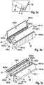
- FIG. 3a shows a cutout 30 of a closure plate 20 (3), 20 (4), a cutout 32 of a pressure plate 20 (1), 20 (2), a cutout 31 of a fastening means 20 (1a), 20 (lb), 20 (2b) , And a section 33 of a further fastening means.
- the attachment means 20 (1a), 20 (Ib), 20 (2b) comprises an S-shaped guide rail, the S-shaped guide rail having an S-shaped groove of the attachment means 20 (3a), 20 (3b). , 20 (4a), wherein the s-shaped groove has a shape inverted to the s-shaped guide rail.
- the fastening means 20 (3a), 20 (3b), 20 (4a) comprise a further fastening means with a recess 33 for a second connection technique, for example by screws, by a snap connection and / or by a press connection.
- FIGS. 3b and 3c show a battery module 26 with twelve battery cells 25 before ( FIG. 3b ) or after ( Figure 3c ) a telescoping of the fastening means 20 (la), 20 (3b) and 20 (3a), 20 (2b) and 20 (4a), 20 (lb) and 20 (2a), 20 (4b), whereby a Holder is formed, wherein by a connection between the pressure plates 20 (1), 20 (2) and the end plates 20 (3), 20 (4) the battery cells are held together to form a battery module 26.
- the pressure plates 20 (1), 20 (2) can be screwed to the end plates 20 (3), 20 (4), for example, whereby a more stable connection is achieved and / or whereby a pushing apart of the pressure plates 20 (1), 20 (2) and the end plates 20 (3), 20 (4), for example, by shaking the vehicle is prevented.
Landscapes
- Chemical & Material Sciences (AREA)
- Chemical Kinetics & Catalysis (AREA)
- Electrochemistry (AREA)
- General Chemical & Material Sciences (AREA)
- Battery Mounting, Suspending (AREA)
Description
- Die Erfindung geht aus von einer Halterung mindestens einer Batteriezelle umfassend mindestens zwei Halterungselemente.
- Aus dem Stand der Technik sind verschweißte Halterungen bekannt, die Batteriezellen unter einem hohen Anpressdruck in einem Batteriemodul zusammenhalten.
- Die Druckschrift
EP 1 505 670 A2 offenbart eine Batterieanordnung mit einer Vielzahl von Zellen, die parallel zueinander positioniert sind. Zwei Sammelschienen sind über alle ersten Terminals und alle zweiten Terminals positioniert. Jede der Sammelschienen enthält Schlitze, durch die sich die Terminals erstrecken und über die Stromschiene gebogen werden können. Diese Batterieanordnung ermöglicht die Verbindung von mehr als drei Zellen miteinander und verbessert den Luftstrom durch die Batterieanordnung. - Die Druckschrift
FR 2 691 292 A3 - Öffnungen (11, 12) an der Oberseite einer langen Seite ermöglichen den Durchlass der Batterie-Terminals.
- Nachteilig an dem bekannten Stand der Technik ist, dass zur Herstellung eines Batteriemoduls die Batteriezellen mittels eines hohen Anpressdrucks zusammengedrückt werden müssen, wodurch keine exakte Positionierung der Batteriezellen möglich ist, beispielsweise um eine gleichmäßige Wärmeabfuhr der Batteriezellen zu ermöglichen, und wodurch aufgrund von Fertigungstoleranzen keine formschlüssige Verbindung zwischen der Halterung und den Batteriezellen möglich ist.
- Die erfindungsgemäße Vorgehensweise mit den kennzeichnenden Merkmalen der unabhängigen Ansprüche weist demgegenüber den Vorteil auf, dass eine Halterung mindestens einer Batteriezelle mittels mindestens zwei Halterungselementen hergestellt wird, wodurch eine exakte Positionierung mindestens einer Batteriezelle und eine formschlüssige Verbindung zwischen der Halterung und der Batteriezelle möglich ist.
- Die Halterung der mindestens einen Batteriezelle umfasst mindestens zwei Halterungselemente, wobei jedes Halterungselement mindestens ein Befestigungsmittel umfasst und vorteilhafterweise die mindestens zwei Halterungselemente mittels der Befestigungsmittel mechanisch lösbar verbunden sind, wobei erste Befestigungsmittel eine s-förmige Führungsschiene aufweisen, die einer invertierten Form, insbesondere einer im Wesentlichen s-förmigen Nut, zweiter Befestigungsmittel entsprechen, wobei die Verbindung zwischen den
- Halterungselementen und der Batteriezelle formschlüssig ist, wobei die Halterung Stirnflächen und Seitenflächen der mindestens einen Batteriezelle im Wesentlichen vollständig umschließt.
- Vorteilhafterweise weist ein Befestigungsmittel eines ersten Halterungselements eine Form auf, die einer invertierten Form eines Befestigungsmittels eines zweiten Halterungselements entspricht. Durch Variieren einer Größe der Form bzw. der invertierten Form wird vorteilhafterweise die Haftreibung zwischen den Formen festgelegt, beispielsweise wird mit einem geringen Abstand zwischen den Formen eine besonders rüttelfeste Verbindung hergestellt. Vorteilhafterweise umfasst die eine Form eine Führungsschiene und die invertierte Form eine Rille, eine Nut und/oder Kerbe. Die Befestigungsmittel umfassen vorteilhafterweise eine Geometrieform, beispielsweise eine s-förmige Biegung, durch die eine besonders zugfeste und/oder druckbelastbare und/oder rüttelfeste Verbindung entsteht.
- Die Verbindung zwischen den Halterungselementen und der Batteriezelle ist vorteilhafterweise formschlüssig, wodurch eine besonders gleichmäßige Wärmeabfuhr der Batteriezellen erfolgt.
- Weitere vorteilhafte Ausführungsformen der vorliegenden Erfindung sind Gegenstand der Unteransprüche.
- Vorteilhafterweise sind das erste Halterungselement und das zweite Halterungselement in einem rechten Winkel verbunden, wodurch eine besonders zugfeste und/oder druckbelastbare Verbindung entsteht.
- Vorteilhafterweise umfasst die Halterung Anpressplatten, die eine Ausrichtung der Batteriezellen ermöglichen, und Abschlussplatten, die das Batteriemodul begrenzen und mit den Anpressplatten verbunden sind. Werden die Batteriezellen wie in herkömmlichen Batteriemodulen in Reihe angeordnet, wobei eine Berührung zwischen zwei Batteriezellen durch jeweils eine Stirnfläche der Batteriezellen erfolgt, dann ist die Anpressplatte entlang einer horizontalen Ausdehnung von Seitenflächen der Batteriezellen mit den Batteriezellen verbunden. Die Anpressplatten können entlang einer vertikalen Ausdehnung der Seitenflächen der Batteriezellen vollständig mit den Batteriezellen verbunden sein. Die Abschlussplatten sind mit den, von den anderen Batteriezellen abgewandten, Stirnflächen einer jeweils ersten Batteriezelle und einer letzten Batteriezelle eines Batteriemoduls verbunden. Ein Material der Abschlussplatte umfasst beispielsweise Kunststoff mit eingepressten Metallröhren, um eine größere Stabilität der Abschlussplatte zu erreichen.
- Dabei wird mittels weiterer Befestigungsmittel der Anpressplatten vorzugsweise eine zusätzliche Verbindung zwischen den Anpressplatten und den Batteriezellen hergestellt, wobei durch die so entstehende Halterung ein besonders verwindungssteifes Batteriemodul entsteht und die Anpressplatten in der Art an den Batteriezellen fixiert sind, dass ein Abgleiten der Halterung verhindert wird.
- Die Halterung der mindestens einen Batteriezelle umfasst mindestens zwei Halterungselemente mit Befestigungsmitteln, wobei die Halterungselemente mittels einer ersten Verbindungstechnik über die Befestigungsmittel miteinander verbunden werden, wobei vorteilhafterweise die Befestigungsmittel ineinander geschoben und/oder ineinander gesteckt und/oder ineinander geklipst sind. Auf diese Weise wird eine einfache Fertigungstechnik gegenüber einem herkömmlichen Schweißverfahren ermöglicht und gegenüber dem Stand der Technik leichtere Materialien, beispielsweise ein Kunststoff, verwendet werden, wodurch eine Gewichtsreduzierung des Batteriemoduls erreicht wird.
- Vorteilhafterweise werden zur Herstellung der Halterung die mindestens zwei Halterungselemente mittels einer zweiten Verbindungstechnik miteinander verbunden, beispielsweise durch Schrauben, durch eine Schnappverbindung und/oder durch eine Pressverbindung, wobei durch die zusätzliche Verbindung vorteilhafterweise eine höhere Zugbelastung, Druckbelastung und/oder Verwindungssteife der Halterung und dadurch des Batteriemoduls erreicht wird.
- Vorteilhafterweise umfasst ein Kraftfahrzeug mindestens ein Batteriemodul, das eine Halterung der mindestens einen Batteriezelle beinhaltet, wobei beispielsweise durch die rüttelfeste Verbindung der Batteriezellen durch die erfindungsgemäße Halterung eine geringere Ausfallwahrscheinlichkeit von Batteriemodulen erreicht wird, beispielsweise durch eine Reduzierung von losen Verbindungen und Beschädigungen an der Halterung, die durch Bewegungen bei Beschleunigungsvorgängen oder Rüttelbewegungen des Kraftfahrzeugs verursacht werden können.
- Vorteilhafterweise werden für die mindestens zwei Halterungselemente Materialien verwendet, beispielsweise ein Leichtmetall wie Aluminium und/oder ein Kunststoff wie beispielsweise Polykarbonat, wodurch eine Gewichtsreduzierung des Batteriemoduls erreicht wird und somit beispielsweise eine Reichweite eines Elektrofahrzeugs verlängert wird.
- Ausführungsbeispiele der Erfindung sind in der Zeichnung dargestellt und in der nachfolgenden Beschreibung näher erläutert.
- Es zeigt:
- Figur 1
- eine Halterung mindestens einer Batteriezelle gemäß dem Stand der Technik;
- Figur 2
- eine Ausführungsform der erfindungsgemäßen Halterung;
- Figur 3a
- eine Ausführungsform einer ersten Verbindungstechnik; und
- Figur 3b, 3c
- eine Ausführungsform eines Verfahren zur Herstellung einer Halterung.
- Gleiche Bezugszeichen bezeichnen in allen Figuren gleiche Vorrichtungskomponenten.
-
Figur 1 zeigt ein Batteriemodul 11 gemäß dem Stand der Technik mit beispielsweise sechs Batteriezellen 10, wobei zur Herstellung des Batteriemoduls 11 die Batteriezellen 10 unter Druck gegeneinander gepresst werden 13(1), 13(2) und eine Halterung 12 während des Gegeneinanderpressens um die Batteriezellen 10 befestigt wird. Die Halterung kann beispielsweise aus mehreren Halterungsteilen 12, 14 bestehen, die miteinander verschweißt sind. InFigur 1 weisen die Halterungsteile 12 und 14 eine unterschiedliche Höhe auf, beispielsweise zur Stabilisierung der Batteriezellen oder für eine Befestigung eines Steuergeräts an dem Batteriemodul 11. -
Figur 2 zeigt ein Batteriemodul 26 mit zwölf Batteriezellen 25, die in Reihe mittels Zellverbindern miteinander elektrisch leitend verbunden sind. In der gezeigten Ausführungsform umfasst eine erfindungsgemäße Halterung vier Halterungselemente 20(1), 20(2), 20(3), 20(4), wobei die vier Halterungselemente 20(1), 20(2), 20(3), 20(4) zwei Anpressplatten 20(1), 20(2) und zwei Abschlussplatten 20(3), 20(4) umfassen. Die Anpressplatten 20(1), 20(2) bzw. die zwei Abschlussplatten 20(3), 20(4) umfassen Befestigungsmittel 20(la), 20(lb), 20(2b) bzw. 20(3a), 20(3b), 20(4a). In der gezeigten Ausführungsform umfassen die Befestigungsmittel 20(3a), 20(3b), 20(4a) jeweils eine Nut, die eine zu jeweils einer Führungsschiene der Befestigungsmittel 20(la), 20(lb), 20(2b) invertierte Form aufweist. So wird beispielsweise durch ein Ineinanderschieben einer Nut und einer Führungsschiene eine Verbindung zwischen der Anpressplatte 20(1), 20(2) und mindestens einer der Abschlussplatten 20(3), 20(4) erreicht. Die Anpressplatten 20(1), 20(2) umfassen ein weiteres Befestigungsmittel 20(lc), 20(2c) mit einer zu einem Befestigungsmittel 25(c) der Batteriezellen 25 invertierten Form, so dass zusätzliche eine Verbindung zwischen der Anpressplatte 20(1), 20(2) und den Batteriezellen 25 hergestellt wird, beispielsweise zur Stabilisierung der Anpressplatten 20(1), 20(2). Vorteilhafterweise sind die Befestigungsmittel 25(c) eine Rille an einer Oberseite der Batteriezellen 25 welche im Wesentlichen parallel zu den Anpressplatten 20(1), 20(2) verläuft. -
Figur 3a zeigt einen Ausschnitt 30 einer Abschlussplatte 20(3), 20(4), einen Ausschnitt 32 einer Anpressplatte 20(1), 20(2), einen Ausschnitt 31 eines Befestigungsmittels 20(1a), 20(lb), 20(2b), sowie einen Ausschnitt 33 eines weiteren Befestigungsmittels. In der gezeigten Ausführungsform umfasst das Befestigungsmittel 20(la), 20(lb), 20(2b) eine s-förmige Führungsschiene, wobei die s-förmige Führungsschiene mit einer s-förmige Nut der Befestigungsmittel 20(3a), 20(3b), 20(4a), miteinander verbunden sind, wobei die s-förmige Nut eine zu der s-förmigen Führungsschiene invertierte Form aufweist. Die Befestigungsmittel 20(3a), 20(3b), 20(4a) umfassen ein weiteres Befestigungsmittel mit einer Aussparung 33 für eine zweite Verbindungstechnik, beispielsweise durch Schrauben, durch eine Schnappverbindung und/oder durch eine Pressverbindung. - Die
Figuren 3b und 3c zeigen ein Batteriemodul 26 mit zwölf Batteriezellen 25 vor (Figur 3b ) bzw. nach (Figur 3c ) einem Ineinanderschieben der Befestigungsmittel 20(la), 20(3b) bzw. 20(3a), 20(2b) bzw. 20(4a), 20(lb) bzw. 20(2a), 20(4b), wodurch eine Halterung entsteht, wobei durch eine Verbindung zwischen den Anpressplatten 20(1), 20(2) und den Abschlussplatten 20(3), 20(4) die Batteriezellen zu einem Batteriemodul 26 zusammengehalten werden. Die Halterung umschließt im Wesentlichen vollständig Stirnflächen und Seitenflächen der Batteriezellen (25) Mittels der mindestens einen Aussparung 33 können die Anpressplatten 20(1), 20(2) mit den Abschlussplatten 20(3), 20(4) beispielsweise verschraubt werden, wodurch eine stabilere Verbindung erreicht wird und/oder wodurch ein Auseinanderschieben der Anpressplatten 20(1), 20(2) und der Abschlussplatten 20(3), 20(4), beispielsweise durch Rüttelbewegungen des Fahrzeugs, verhindert wird.
Claims (6)
- Halterung mindestens einer Batteriezelle (25), wobei die Halterung mindestens zwei Halterungselemente (20(1), 20(2), 20(3), 20(4)) umfasst, wobei jedes Halterungselement (20(1), 20(2), 20(3), 20(4)) mindestens ein Befestigungsmittel (20(la), 20(2a), 20(3a), 20(4a), 20(lb), 20(2b), 20(3b), 20(4b)) umfasst, dadurch gekennzeichnet, dass die mindestens zwei Halterungselemente ((20(1), 20(2), 20(3), 20(4))) mittels der Befestigungsmittel (20(la), 20(2a), 20(3a), 20(4a), 20(lb), 20(2b), 20(3b), 20(4b)) mechanisch lösbar verbunden sind, wobei erste Befestigungsmittel (20(la), 20(lb), 20(2a), 20(2b)) eine s-förmige Führungsschiene aufweisen, die einer invertierten Form, insbesondere einer im Wesentlichen s-förmigen Nut, zweiter Befestigungsmittel (20(3a), 20(3b), 20(4a), 20(4b) entsprechen, wobei die Verbindung zwischen den Halterungselementen (20(1), 20(2), 20(3), 20(4)) und der Batteriezelle (25) formschlüssig ist, wobei die Halterung Stirnflächen und Seitenflächen der mindestens einen Batteriezelle (25) im Wesentlichen vollständig umschließt.
- Halterung nach einem der vorherigen Ansprüche, dadurch gekennzeichnet, dass ein erstes Halterungselement (20(1), 20(2), 20(3), 20(4)) und ein zweites Halterungselement (20(1), 20(2), 20(3), 20(4)) in einem rechten Winkel zueinander verbunden sind.
- Batteriemodul (26) umfassend mindestens eine Batteriezelle (25) mit einer Halterung nach einem der Ansprüche 1 bis 3.
- Kraftfahrzeug mit mindestens einem Batteriemodul (26) nach Anspruch 3.
- Verfahren zur Herstellung einer Halterung mindestens einer Batteriezelle (25), wobei die Halterung mindestens zwei Halterungselemente (20(1), 20(2), 20(3), 20(4)) umfasst, wobei jedes Halterungselement (20(1), 20(2), 20(3), 20(4)) mindestens ein Befestigungsmittel (20(la), 20(2a), 20(3a), 20(4a), 20(lb), 20(2b), 20(3b), 20(4b)) umfasst, dadurch gekennzeichnet, dass die mindestens zwei Halterungselemente (20(1), 20(2), 20(3), 20(4)) mittels der Befestigungsmittel (20(la), 20(2a), 20(3a), 20(4a), 20(lb), 20(2b), 20(3b), 20(4b)) mittels einer Schiebetechnik verbunden werden, bei der die s-förmige Führungsschiene der Befestigungsmittel (20(la), 20(1b), 20(2a), 20(2b)) in die s-förmige Nut der Befestigungsmittel (20(3a), 20(3b), 20(4a), 20(4b)) für eine formschlüssige Verbindung ineinander geschoben werden, wobei die Halterung Stirnflächen und Seitenflächen der mindestens einen Batteriezelle (25) in Wesentlichen vollständig umschließt.
- Verfahren nach einem der Ansprüche 5, dadurch gekennzeichnet, dass die Befestigungsmittel (20(1a), 20(2a), 20(3a), 20(4a), 20(1b), 20(2b), 20(3b), 20(4b)) der Halterungselemente (20(1), 20(2), 20(3), 20(4)) mittels einer zweiten Verbindungstechnik miteinander verbunden werden, wobei die zweite Verbindungstechnik Mittel für eine Verriegelung der Befestigungsmittel (20(la), 20(2a), 20(3a), 20(4a), 20(lb), 20(2b), 20(3b), 20(4b)) und/oder eine Verschraubung der Befestigungsmittel (20(la), 20(2a), 20(3a), 20(4a), 20(1b), 20(2b), 20(3b), 20(4b)) der Halterungselemente (20(1), 20(2), 20(3), 20(4)) umfasst.
Applications Claiming Priority (2)
| Application Number | Priority Date | Filing Date | Title |
|---|---|---|---|
| DE102013216070.4A DE102013216070A1 (de) | 2013-08-14 | 2013-08-14 | Halterung mindestens einer Batteriezelle |
| PCT/EP2014/067133 WO2015022279A1 (de) | 2013-08-14 | 2014-08-08 | Halterung mindestens einer batteriezelle |
Publications (2)
| Publication Number | Publication Date |
|---|---|
| EP3033781A1 EP3033781A1 (de) | 2016-06-22 |
| EP3033781B1 true EP3033781B1 (de) | 2018-10-10 |
Family
ID=51300763
Family Applications (1)
| Application Number | Title | Priority Date | Filing Date |
|---|---|---|---|
| EP14749841.4A Active EP3033781B1 (de) | 2013-08-14 | 2014-08-08 | Halterung mindestens einer batteriezelle |
Country Status (5)
| Country | Link |
|---|---|
| US (1) | US10290844B2 (de) |
| EP (1) | EP3033781B1 (de) |
| CN (1) | CN105431963A (de) |
| DE (1) | DE102013216070A1 (de) |
| WO (1) | WO2015022279A1 (de) |
Families Citing this family (4)
| Publication number | Priority date | Publication date | Assignee | Title |
|---|---|---|---|---|
| WO2019056269A1 (zh) * | 2017-09-21 | 2019-03-28 | 宁德时代新能源科技股份有限公司 | 固定架、电池单元及电池模组 |
| CN110085780A (zh) * | 2019-05-31 | 2019-08-02 | 杭州捷能科技有限公司 | 一种轻质高强度的电池模组 |
| EP3758130B1 (de) * | 2019-06-25 | 2023-10-04 | INVENOX GmbH | Aufnahmevorrichtung zur aufnahme und kühlung von einschubmodulen |
| DE102022126444B3 (de) | 2022-10-12 | 2023-12-14 | Audi Aktiengesellschaft | Sicherungselement für eine Abschlussplatte einer Batterieanordnung |
Family Cites Families (15)
| Publication number | Priority date | Publication date | Assignee | Title |
|---|---|---|---|---|
| ATA543875A (de) * | 1975-07-14 | 1977-01-15 | Semperit Ag | Akkumulatorgehause aus thermoplastischem strukturschaumstoff |
| JPH04337263A (ja) | 1991-05-14 | 1992-11-25 | Fujikura Ltd | コネクタハウジング |
| FR2691292B3 (fr) * | 1992-05-18 | 1994-05-20 | Bracker Patrick | Dispositif de protection pour batterie de vehicule. |
| JPH1197095A (ja) | 1997-09-17 | 1999-04-09 | Sumitomo Wiring Syst Ltd | リテーナ付きコネクタ |
| EP0952620B1 (de) * | 1998-03-25 | 2002-11-20 | Matsushita Electric Industrial Co., Ltd. | Verschlossener Akkumulator und entsprechendes moduläres System |
| FR2827309B1 (fr) * | 2001-07-13 | 2004-05-14 | Centre Nat Rech Scient | Procede de fabrication de materiaux composites diamantes |
| US6871829B2 (en) * | 2003-01-23 | 2005-03-29 | Quick Cable Corporation | Telescopically adjustable battery holddown |
| US7118827B2 (en) | 2003-08-06 | 2006-10-10 | Delphi Technologies, Inc. | Battery assembly and method of making same |
| JP2011018522A (ja) | 2009-07-08 | 2011-01-27 | Sumitomo Wiring Syst Ltd | コネクタ |
| KR101146677B1 (ko) | 2009-10-30 | 2012-05-22 | 에스비리모티브 주식회사 | 버스바홀더 |
| US8808907B2 (en) * | 2010-06-09 | 2014-08-19 | Nissan Motor Co., Ltd. | Battery module |
| TWM401877U (en) * | 2010-11-08 | 2011-04-11 | han-xi Huang | Water-proof battery box |
| CN201998780U (zh) * | 2011-01-29 | 2011-10-05 | 东莞市绿通高尔夫观光车有限公司 | 抽拉式电动车电池架 |
| DE102012224041B4 (de) * | 2011-12-22 | 2022-02-03 | GM Global Technology Operations, LLC (n.d. Ges. d. Staates Delaware) | Modular erweiterbare Baugruppe für einen modularen Kraftfahrzeug-Batteriepack sowie solch ein Batteriepack |
| CN202617530U (zh) * | 2012-04-10 | 2012-12-19 | 杭州恒胜电子科技有限公司 | 一种控制器外壳 |
-
2013
- 2013-08-14 DE DE102013216070.4A patent/DE102013216070A1/de not_active Withdrawn
-
2014
- 2014-08-08 EP EP14749841.4A patent/EP3033781B1/de active Active
- 2014-08-08 CN CN201480045347.6A patent/CN105431963A/zh active Pending
- 2014-08-08 US US14/911,891 patent/US10290844B2/en active Active
- 2014-08-08 WO PCT/EP2014/067133 patent/WO2015022279A1/de not_active Ceased
Non-Patent Citations (1)
| Title |
|---|
| None * |
Also Published As
| Publication number | Publication date |
|---|---|
| US20160204402A1 (en) | 2016-07-14 |
| CN105431963A (zh) | 2016-03-23 |
| DE102013216070A1 (de) | 2015-03-12 |
| US10290844B2 (en) | 2019-05-14 |
| EP3033781A1 (de) | 2016-06-22 |
| WO2015022279A1 (de) | 2015-02-19 |
Similar Documents
| Publication | Publication Date | Title |
|---|---|---|
| EP2719564B1 (de) | Batteriesystem für ein Kraftfahrzeug | |
| EP2936005B1 (de) | Photovoltaiksystem | |
| EP2718994B1 (de) | Batterie, kraftfahrzeug mit dieser batterie und verfahren zur montage dieser batterie | |
| EP2619823A1 (de) | Rahmensystem für batteriezellen sowie batteriemodul | |
| DE102011000696B4 (de) | Elektrischer Energiespeicher eines Kraftfahrzeugs | |
| DE102016110787A1 (de) | Batteriegehäuse einer Traktionsbatterie eines Kraftfahrzeugs | |
| WO2018197202A1 (de) | Akkumulatoranordnung | |
| DE102012218473A1 (de) | Energiespeicheranordnung und Montagevorrichtung | |
| DE102012014775A1 (de) | Vorrichtung zur Anordnung von Batteriemodulen in einer Fahrzeugbatterie | |
| DE102016205920A1 (de) | Batteriepack | |
| DE102013200930A1 (de) | Mechanische Kopplung von wenigstens zwei benachbart zueinander angeordneten Akkumulatormodulen | |
| WO2015022279A1 (de) | Halterung mindestens einer batteriezelle | |
| DE102019220260A1 (de) | Hochvoltbatterie für ein Fahrzeug | |
| DE102012205175A1 (de) | Kühlmodulfixierung | |
| DE202010015763U1 (de) | Vorrichtung zur Positionierung wenigstens eines Rundsteckers | |
| DE102006010064A1 (de) | Aufnahme für Befestigungselement | |
| DE102017107724B4 (de) | Haltevorrichtung für ein Mobilgerät und Verfahren zur Herstellung einer Haltevorrichtung | |
| DE112012006580T5 (de) | Flüssigkristallanzeigevorrichtung sowie Hintergrundbeleuchtungsmodul und Rückplattenbaugruppe | |
| EP3656191B1 (de) | E-schrank für ein fahrzeug sowie montageverfahren für einen e-schrank | |
| DE19809935C2 (de) | Verfahren zum Verbinden eines Stoßfängers | |
| DE202022107183U1 (de) | Tragkonstruktion für eine Photovoltaik-Anlage | |
| DE102010051001A1 (de) | Vorrichtung zur Aufnahme und Halterung einer Hochvoltbatterie | |
| DE102016222643A1 (de) | Baukastensystem umfassend ein einteilig ausgebildetes Gehäuse sowie einen einsetzbaren Rahmen | |
| DE102017112366A1 (de) | Batteriemodul mit Kühlsystem | |
| DE102021120656A1 (de) | Batteriemodul, Batteriewanne und Verfahren zur Herstellung einer Batteriewanne |
Legal Events
| Date | Code | Title | Description |
|---|---|---|---|
| PUAI | Public reference made under article 153(3) epc to a published international application that has entered the european phase |
Free format text: ORIGINAL CODE: 0009012 |
|
| 17P | Request for examination filed |
Effective date: 20160314 |
|
| AK | Designated contracting states |
Kind code of ref document: A1 Designated state(s): AL AT BE BG CH CY CZ DE DK EE ES FI FR GB GR HR HU IE IS IT LI LT LU LV MC MK MT NL NO PL PT RO RS SE SI SK SM TR |
|
| AX | Request for extension of the european patent |
Extension state: BA ME |
|
| DAX | Request for extension of the european patent (deleted) | ||
| STAA | Information on the status of an ep patent application or granted ep patent |
Free format text: STATUS: EXAMINATION IS IN PROGRESS |
|
| 17Q | First examination report despatched |
Effective date: 20170322 |
|
| GRAP | Despatch of communication of intention to grant a patent |
Free format text: ORIGINAL CODE: EPIDOSNIGR1 |
|
| STAA | Information on the status of an ep patent application or granted ep patent |
Free format text: STATUS: GRANT OF PATENT IS INTENDED |
|
| INTG | Intention to grant announced |
Effective date: 20180529 |
|
| GRAS | Grant fee paid |
Free format text: ORIGINAL CODE: EPIDOSNIGR3 |
|
| GRAA | (expected) grant |
Free format text: ORIGINAL CODE: 0009210 |
|
| STAA | Information on the status of an ep patent application or granted ep patent |
Free format text: STATUS: THE PATENT HAS BEEN GRANTED |
|
| AK | Designated contracting states |
Kind code of ref document: B1 Designated state(s): AL AT BE BG CH CY CZ DE DK EE ES FI FR GB GR HR HU IE IS IT LI LT LU LV MC MK MT NL NO PL PT RO RS SE SI SK SM TR |
|
| REG | Reference to a national code |
Ref country code: GB Ref legal event code: FG4D Free format text: NOT ENGLISH |
|
| REG | Reference to a national code |
Ref country code: CH Ref legal event code: EP Ref country code: AT Ref legal event code: REF Ref document number: 1052275 Country of ref document: AT Kind code of ref document: T Effective date: 20181015 |
|
| REG | Reference to a national code |
Ref country code: IE Ref legal event code: FG4D Free format text: LANGUAGE OF EP DOCUMENT: GERMAN |
|
| REG | Reference to a national code |
Ref country code: DE Ref legal event code: R096 Ref document number: 502014009724 Country of ref document: DE |
|
| REG | Reference to a national code |
Ref country code: NL Ref legal event code: MP Effective date: 20181010 |
|
| REG | Reference to a national code |
Ref country code: LT Ref legal event code: MG4D |
|
| PG25 | Lapsed in a contracting state [announced via postgrant information from national office to epo] |
Ref country code: NL Free format text: LAPSE BECAUSE OF FAILURE TO SUBMIT A TRANSLATION OF THE DESCRIPTION OR TO PAY THE FEE WITHIN THE PRESCRIBED TIME-LIMIT Effective date: 20181010 |
|
| PG25 | Lapsed in a contracting state [announced via postgrant information from national office to epo] |
Ref country code: FI Free format text: LAPSE BECAUSE OF FAILURE TO SUBMIT A TRANSLATION OF THE DESCRIPTION OR TO PAY THE FEE WITHIN THE PRESCRIBED TIME-LIMIT Effective date: 20181010 Ref country code: IS Free format text: LAPSE BECAUSE OF FAILURE TO SUBMIT A TRANSLATION OF THE DESCRIPTION OR TO PAY THE FEE WITHIN THE PRESCRIBED TIME-LIMIT Effective date: 20190210 Ref country code: NO Free format text: LAPSE BECAUSE OF FAILURE TO SUBMIT A TRANSLATION OF THE DESCRIPTION OR TO PAY THE FEE WITHIN THE PRESCRIBED TIME-LIMIT Effective date: 20190110 Ref country code: LT Free format text: LAPSE BECAUSE OF FAILURE TO SUBMIT A TRANSLATION OF THE DESCRIPTION OR TO PAY THE FEE WITHIN THE PRESCRIBED TIME-LIMIT Effective date: 20181010 Ref country code: HR Free format text: LAPSE BECAUSE OF FAILURE TO SUBMIT A TRANSLATION OF THE DESCRIPTION OR TO PAY THE FEE WITHIN THE PRESCRIBED TIME-LIMIT Effective date: 20181010 Ref country code: PL Free format text: LAPSE BECAUSE OF FAILURE TO SUBMIT A TRANSLATION OF THE DESCRIPTION OR TO PAY THE FEE WITHIN THE PRESCRIBED TIME-LIMIT Effective date: 20181010 Ref country code: BG Free format text: LAPSE BECAUSE OF FAILURE TO SUBMIT A TRANSLATION OF THE DESCRIPTION OR TO PAY THE FEE WITHIN THE PRESCRIBED TIME-LIMIT Effective date: 20190110 Ref country code: ES Free format text: LAPSE BECAUSE OF FAILURE TO SUBMIT A TRANSLATION OF THE DESCRIPTION OR TO PAY THE FEE WITHIN THE PRESCRIBED TIME-LIMIT Effective date: 20181010 Ref country code: LV Free format text: LAPSE BECAUSE OF FAILURE TO SUBMIT A TRANSLATION OF THE DESCRIPTION OR TO PAY THE FEE WITHIN THE PRESCRIBED TIME-LIMIT Effective date: 20181010 |
|
| PG25 | Lapsed in a contracting state [announced via postgrant information from national office to epo] |
Ref country code: PT Free format text: LAPSE BECAUSE OF FAILURE TO SUBMIT A TRANSLATION OF THE DESCRIPTION OR TO PAY THE FEE WITHIN THE PRESCRIBED TIME-LIMIT Effective date: 20190210 Ref country code: AL Free format text: LAPSE BECAUSE OF FAILURE TO SUBMIT A TRANSLATION OF THE DESCRIPTION OR TO PAY THE FEE WITHIN THE PRESCRIBED TIME-LIMIT Effective date: 20181010 Ref country code: RS Free format text: LAPSE BECAUSE OF FAILURE TO SUBMIT A TRANSLATION OF THE DESCRIPTION OR TO PAY THE FEE WITHIN THE PRESCRIBED TIME-LIMIT Effective date: 20181010 Ref country code: SE Free format text: LAPSE BECAUSE OF FAILURE TO SUBMIT A TRANSLATION OF THE DESCRIPTION OR TO PAY THE FEE WITHIN THE PRESCRIBED TIME-LIMIT Effective date: 20181010 Ref country code: GR Free format text: LAPSE BECAUSE OF FAILURE TO SUBMIT A TRANSLATION OF THE DESCRIPTION OR TO PAY THE FEE WITHIN THE PRESCRIBED TIME-LIMIT Effective date: 20190111 |
|
| REG | Reference to a national code |
Ref country code: DE Ref legal event code: R097 Ref document number: 502014009724 Country of ref document: DE |
|
| PG25 | Lapsed in a contracting state [announced via postgrant information from national office to epo] |
Ref country code: IT Free format text: LAPSE BECAUSE OF FAILURE TO SUBMIT A TRANSLATION OF THE DESCRIPTION OR TO PAY THE FEE WITHIN THE PRESCRIBED TIME-LIMIT Effective date: 20181010 Ref country code: CZ Free format text: LAPSE BECAUSE OF FAILURE TO SUBMIT A TRANSLATION OF THE DESCRIPTION OR TO PAY THE FEE WITHIN THE PRESCRIBED TIME-LIMIT Effective date: 20181010 Ref country code: DK Free format text: LAPSE BECAUSE OF FAILURE TO SUBMIT A TRANSLATION OF THE DESCRIPTION OR TO PAY THE FEE WITHIN THE PRESCRIBED TIME-LIMIT Effective date: 20181010 |
|
| PLBE | No opposition filed within time limit |
Free format text: ORIGINAL CODE: 0009261 |
|
| STAA | Information on the status of an ep patent application or granted ep patent |
Free format text: STATUS: NO OPPOSITION FILED WITHIN TIME LIMIT |
|
| PG25 | Lapsed in a contracting state [announced via postgrant information from national office to epo] |
Ref country code: RO Free format text: LAPSE BECAUSE OF FAILURE TO SUBMIT A TRANSLATION OF THE DESCRIPTION OR TO PAY THE FEE WITHIN THE PRESCRIBED TIME-LIMIT Effective date: 20181010 Ref country code: SK Free format text: LAPSE BECAUSE OF FAILURE TO SUBMIT A TRANSLATION OF THE DESCRIPTION OR TO PAY THE FEE WITHIN THE PRESCRIBED TIME-LIMIT Effective date: 20181010 Ref country code: SM Free format text: LAPSE BECAUSE OF FAILURE TO SUBMIT A TRANSLATION OF THE DESCRIPTION OR TO PAY THE FEE WITHIN THE PRESCRIBED TIME-LIMIT Effective date: 20181010 Ref country code: EE Free format text: LAPSE BECAUSE OF FAILURE TO SUBMIT A TRANSLATION OF THE DESCRIPTION OR TO PAY THE FEE WITHIN THE PRESCRIBED TIME-LIMIT Effective date: 20181010 |
|
| 26N | No opposition filed |
Effective date: 20190711 |
|
| PG25 | Lapsed in a contracting state [announced via postgrant information from national office to epo] |
Ref country code: SI Free format text: LAPSE BECAUSE OF FAILURE TO SUBMIT A TRANSLATION OF THE DESCRIPTION OR TO PAY THE FEE WITHIN THE PRESCRIBED TIME-LIMIT Effective date: 20181010 |
|
| PG25 | Lapsed in a contracting state [announced via postgrant information from national office to epo] |
Ref country code: TR Free format text: LAPSE BECAUSE OF FAILURE TO SUBMIT A TRANSLATION OF THE DESCRIPTION OR TO PAY THE FEE WITHIN THE PRESCRIBED TIME-LIMIT Effective date: 20181010 |
|
| PG25 | Lapsed in a contracting state [announced via postgrant information from national office to epo] |
Ref country code: LU Free format text: LAPSE BECAUSE OF NON-PAYMENT OF DUE FEES Effective date: 20190808 Ref country code: LI Free format text: LAPSE BECAUSE OF NON-PAYMENT OF DUE FEES Effective date: 20190831 Ref country code: CH Free format text: LAPSE BECAUSE OF NON-PAYMENT OF DUE FEES Effective date: 20190831 Ref country code: MC Free format text: LAPSE BECAUSE OF FAILURE TO SUBMIT A TRANSLATION OF THE DESCRIPTION OR TO PAY THE FEE WITHIN THE PRESCRIBED TIME-LIMIT Effective date: 20181010 |
|
| REG | Reference to a national code |
Ref country code: BE Ref legal event code: MM Effective date: 20190831 |
|
| PG25 | Lapsed in a contracting state [announced via postgrant information from national office to epo] |
Ref country code: IE Free format text: LAPSE BECAUSE OF NON-PAYMENT OF DUE FEES Effective date: 20190808 |
|
| PG25 | Lapsed in a contracting state [announced via postgrant information from national office to epo] |
Ref country code: BE Free format text: LAPSE BECAUSE OF NON-PAYMENT OF DUE FEES Effective date: 20190831 |
|
| REG | Reference to a national code |
Ref country code: AT Ref legal event code: MM01 Ref document number: 1052275 Country of ref document: AT Kind code of ref document: T Effective date: 20190808 |
|
| REG | Reference to a national code |
Ref country code: DE Ref legal event code: R079 Ref document number: 502014009724 Country of ref document: DE Free format text: PREVIOUS MAIN CLASS: H01M0002100000 Ipc: H01M0050200000 |
|
| PG25 | Lapsed in a contracting state [announced via postgrant information from national office to epo] |
Ref country code: AT Free format text: LAPSE BECAUSE OF NON-PAYMENT OF DUE FEES Effective date: 20190808 |
|
| PG25 | Lapsed in a contracting state [announced via postgrant information from national office to epo] |
Ref country code: CY Free format text: LAPSE BECAUSE OF FAILURE TO SUBMIT A TRANSLATION OF THE DESCRIPTION OR TO PAY THE FEE WITHIN THE PRESCRIBED TIME-LIMIT Effective date: 20181010 |
|
| PG25 | Lapsed in a contracting state [announced via postgrant information from national office to epo] |
Ref country code: MT Free format text: LAPSE BECAUSE OF FAILURE TO SUBMIT A TRANSLATION OF THE DESCRIPTION OR TO PAY THE FEE WITHIN THE PRESCRIBED TIME-LIMIT Effective date: 20181010 Ref country code: HU Free format text: LAPSE BECAUSE OF FAILURE TO SUBMIT A TRANSLATION OF THE DESCRIPTION OR TO PAY THE FEE WITHIN THE PRESCRIBED TIME-LIMIT; INVALID AB INITIO Effective date: 20140808 |
|
| PG25 | Lapsed in a contracting state [announced via postgrant information from national office to epo] |
Ref country code: MK Free format text: LAPSE BECAUSE OF FAILURE TO SUBMIT A TRANSLATION OF THE DESCRIPTION OR TO PAY THE FEE WITHIN THE PRESCRIBED TIME-LIMIT Effective date: 20181010 |
|
| PGFP | Annual fee paid to national office [announced via postgrant information from national office to epo] |
Ref country code: GB Payment date: 20220824 Year of fee payment: 9 |
|
| PGFP | Annual fee paid to national office [announced via postgrant information from national office to epo] |
Ref country code: FR Payment date: 20220822 Year of fee payment: 9 |
|
| GBPC | Gb: european patent ceased through non-payment of renewal fee |
Effective date: 20230808 |
|
| PG25 | Lapsed in a contracting state [announced via postgrant information from national office to epo] |
Ref country code: GB Free format text: LAPSE BECAUSE OF NON-PAYMENT OF DUE FEES Effective date: 20230808 |
|
| PG25 | Lapsed in a contracting state [announced via postgrant information from national office to epo] |
Ref country code: GB Free format text: LAPSE BECAUSE OF NON-PAYMENT OF DUE FEES Effective date: 20230808 Ref country code: FR Free format text: LAPSE BECAUSE OF NON-PAYMENT OF DUE FEES Effective date: 20230831 |
|
| PGFP | Annual fee paid to national office [announced via postgrant information from national office to epo] |
Ref country code: DE Payment date: 20251021 Year of fee payment: 12 |