EP3033742B1 - Système et procédé pour le déploiement d'audio/vidéo et d'événements au moyen d'un système de positionnement - Google Patents
Système et procédé pour le déploiement d'audio/vidéo et d'événements au moyen d'un système de positionnement Download PDFInfo
- Publication number
- EP3033742B1 EP3033742B1 EP14752470.6A EP14752470A EP3033742B1 EP 3033742 B1 EP3033742 B1 EP 3033742B1 EP 14752470 A EP14752470 A EP 14752470A EP 3033742 B1 EP3033742 B1 EP 3033742B1
- Authority
- EP
- European Patent Office
- Prior art keywords
- security
- image data
- mobile user
- alarm conditions
- position information
- Prior art date
- Legal status (The legal status is an assumption and is not a legal conclusion. Google has not performed a legal analysis and makes no representation as to the accuracy of the status listed.)
- Not-in-force
Links
- 238000000034 method Methods 0.000 title claims description 11
- 230000004044 response Effects 0.000 claims description 12
- 239000000284 extract Substances 0.000 claims description 4
- 238000012544 monitoring process Methods 0.000 claims description 3
- 238000010586 diagram Methods 0.000 description 10
- 230000001413 cellular effect Effects 0.000 description 7
- 239000000779 smoke Substances 0.000 description 7
- 230000001960 triggered effect Effects 0.000 description 5
- 238000013459 approach Methods 0.000 description 1
- 239000000872 buffer Substances 0.000 description 1
- 238000004891 communication Methods 0.000 description 1
- 238000010276 construction Methods 0.000 description 1
- 238000009434 installation Methods 0.000 description 1
- 239000011159 matrix material Substances 0.000 description 1
- 230000008569 process Effects 0.000 description 1
- 238000012545 processing Methods 0.000 description 1
- 230000003068 static effect Effects 0.000 description 1
- 230000007704 transition Effects 0.000 description 1
Images


Classifications
-
- G—PHYSICS
- G08—SIGNALLING
- G08B—SIGNALLING OR CALLING SYSTEMS; ORDER TELEGRAPHS; ALARM SYSTEMS
- G08B13/00—Burglar, theft or intruder alarms
- G08B13/18—Actuation by interference with heat, light, or radiation of shorter wavelength; Actuation by intruding sources of heat, light, or radiation of shorter wavelength
- G08B13/189—Actuation by interference with heat, light, or radiation of shorter wavelength; Actuation by intruding sources of heat, light, or radiation of shorter wavelength using passive radiation detection systems
- G08B13/194—Actuation by interference with heat, light, or radiation of shorter wavelength; Actuation by intruding sources of heat, light, or radiation of shorter wavelength using passive radiation detection systems using image scanning and comparing systems
- G08B13/196—Actuation by interference with heat, light, or radiation of shorter wavelength; Actuation by intruding sources of heat, light, or radiation of shorter wavelength using passive radiation detection systems using image scanning and comparing systems using television cameras
- G08B13/19602—Image analysis to detect motion of the intruder, e.g. by frame subtraction
- G08B13/19608—Tracking movement of a target, e.g. by detecting an object predefined as a target, using target direction and or velocity to predict its new position
-
- G—PHYSICS
- G08—SIGNALLING
- G08B—SIGNALLING OR CALLING SYSTEMS; ORDER TELEGRAPHS; ALARM SYSTEMS
- G08B13/00—Burglar, theft or intruder alarms
- G08B13/18—Actuation by interference with heat, light, or radiation of shorter wavelength; Actuation by intruding sources of heat, light, or radiation of shorter wavelength
- G08B13/189—Actuation by interference with heat, light, or radiation of shorter wavelength; Actuation by intruding sources of heat, light, or radiation of shorter wavelength using passive radiation detection systems
- G08B13/194—Actuation by interference with heat, light, or radiation of shorter wavelength; Actuation by intruding sources of heat, light, or radiation of shorter wavelength using passive radiation detection systems using image scanning and comparing systems
- G08B13/196—Actuation by interference with heat, light, or radiation of shorter wavelength; Actuation by intruding sources of heat, light, or radiation of shorter wavelength using passive radiation detection systems using image scanning and comparing systems using television cameras
-
- G—PHYSICS
- G08—SIGNALLING
- G08B—SIGNALLING OR CALLING SYSTEMS; ORDER TELEGRAPHS; ALARM SYSTEMS
- G08B25/00—Alarm systems in which the location of the alarm condition is signalled to a central station, e.g. fire or police telegraphic systems
-
- G—PHYSICS
- G08—SIGNALLING
- G08B—SIGNALLING OR CALLING SYSTEMS; ORDER TELEGRAPHS; ALARM SYSTEMS
- G08B25/00—Alarm systems in which the location of the alarm condition is signalled to a central station, e.g. fire or police telegraphic systems
- G08B25/002—Generating a prealarm to the central station
-
- G—PHYSICS
- G08—SIGNALLING
- G08B—SIGNALLING OR CALLING SYSTEMS; ORDER TELEGRAPHS; ALARM SYSTEMS
- G08B27/00—Alarm systems in which the alarm condition is signalled from a central station to a plurality of substations
- G08B27/001—Signalling to an emergency team, e.g. firemen
-
- H—ELECTRICITY
- H04—ELECTRIC COMMUNICATION TECHNIQUE
- H04N—PICTORIAL COMMUNICATION, e.g. TELEVISION
- H04N7/00—Television systems
- H04N7/18—Closed-circuit television [CCTV] systems, i.e. systems in which the video signal is not broadcast
- H04N7/188—Capturing isolated or intermittent images triggered by the occurrence of a predetermined event, e.g. an object reaching a predetermined position
Definitions
- Security systems are often comprised of one or more data networks, security devices, safety devices, network video recorders, video analytics systems, and control systems, to list a few examples.
- the security and safety devices are generally used for monitoring.
- security devices include, but are not limited to, security cameras, motion detectors, access control systems (e.g., keypads, fingerprint scanners, radiofrequency identification (RFID) readers), and security door locks.
- RFID radiofrequency identification
- safety devices include, but are not limited to, smoke detectors and fire alarms.
- the network video recorders (NVRs) receive image data transmitted from the security cameras over the data network and video analytics systems - which may be integrated with the NVRs - interpret the image data to track individuals, monitor usage, or otherwise determine if a security event is occurring.
- a fixed or mobile security device e.g., a mobile panic button among others
- the video analytics systems can interpret image data to determine that a security event is occurring and then signal the alarm condition.
- Motion detectors can sense movement and as a result trigger the alarm condition.
- Access control systems can generate the alarm condition after a number of failed attempts to use an unauthorized keycard, for example.
- Automated door locks can generate the alarm condition when the door is forced or tampering is detected.
- Safety devices can generate an alarm condition when sensing heat or smoke as evidence of a fire.
- Alarm conditions can also be generated by security guards. This function is typically performed by the security guard staffing the control system or a terminal of the control system. In a prototypical example, the security guard watches image data from several security cameras presented on the control system terminal in a matrix format. When a security event is observed, the security guard can "manually" indicate the alarm condition.
- a notification of the alarm condition and possibly the underlying security event is sent to security guards and first responders (such as firemen, emergency medical technicians, or police officers), as appropriate, typically by the security guard that is manning the control system terminal.
- the notification can be transmitted to other security guards via their mobile user devices (e.g., handheld radio transceivers, cellular phones, mobile computing devices (e.g., smartphones, tablets, portable computers), or pagers). If first responders are required, the security guards can contact the appropriate entity or dial "911," which is the national emergency number for the United States.
- US8494481 discloses a mobile alarm device for responding to an alarm condition that has been triggered at a site.
- security guards were dispatched to a security event in response to an alarm condition by the security guard that was manning the control system terminal. This dispatching security guard would note the location of the alarm condition and then consider the known or expected locations of patrolling security guards. The dispatching security guard would then contact the security guards that were closest to the alarm condition and communicate the type of security event and its location.
- GPS Global Positioning System
- GNSS global navigation satellite system
- regional or site-wide positioning systems have become ubiquitous to mobile user devices such as cellular phones, smartphones, tablets, and portable computers, and the cost of these devices has become low enough that they can often be provided to each security guard or first responder or team as basic equipment.
- the present invention can concern a security system that tracks or accesses the position of patrolling security guards or first responders by using position information from positioning systems of mobile user devices carried by those security guards or first responders.
- the security system also determines the location of an alarm condition and then dispatches the security guards or first responders that are best able to respond to the security event of the alarm condition based on the position of those security guards or first responders.
- security systems include more and more security cameras
- the image data generated by those security cameras are useful not only to a dispatching security guard or the security guard that mans the control system terminal but also the security guards or first responders that might be dispatched to security events.
- a fire it would be helpful for firemen to know where in the room a fire is located before entering the room.
- a hostage situation it would be helpful for the police to have real time images before engaging the suspect.
- security guards could view live video of the individual that they are seeking.
- these image data are typically only available to the security guard at the control system terminal, however.
- the image data are pushed from security cameras to the mobile user devices of the security guards or first responders that are dispatched to a security event.
- the security system pushes those video images to the security guards or first responders that are in closest proximity to the location of the alarm condition giving rise to the security event.
- the present invention can be used to only transmit the notification to those security guards or first responders who are in proximity to the security event. By transmitting the image data to a subset of the security guards and first responders, it can reduce the total bandwidth utilized in the data network.
- the present invention can be used to transmit the notification to those security guards or first responders who are in proximity to a predicted path of the subject.
- the present invention can be used to push notifications including the URL(s) of the security cameras that are most useful to the security guard or first responder so that by opening the URL(s), the security guard or first responder can view the security camera's image data without wasting time recalling or searching for the URL(s).
- the invention features a security system comprising: one or more security cameras that capture image data, a network video recorder for storing and distributing the image data from the security cameras, and a security control system that receives position information from mobile user devices and provides access to the image data at the mobile user devices based on the position information relative to locations of alarm conditions.
- the security control system also determines a predicted path of a subject that generated the alarm condition and provides access to the image data at the mobile user devices based on the position information relative to the predicted path of the subject
- the network video recorder includes a video analytics system that analyzes the image data from the security cameras for security events and generates the alarm conditions in response to detecting the security events in the image data.
- the security control system determines the locations of the alarm conditions by accessing position information for the security cameras that generated the image data that gave rise to the alarm conditions.
- the security control system monitors security and/or safety devices for alarm conditions. The security control system then extracts position information from the security and/or safety devices that generated the alarm conditions to determine the locations of the alarm conditions.
- the security control system includes a dispatch service that distributes a reference, e.g., URL, to the image data to one or more mobile user devices in response to the alarm conditions.
- This reference can be distributed by transmitting a message to the one or more mobile user devices.
- the security system can further include one or more fixed or mobile panic button devices that enable users to selectively generate an alarm condition.
- the location of the alarm condition is based on position information for the mobile panic button devices.
- the mobile user devices determine their respective locations and periodically transmit the position information to the security control system.
- the security control system can then store the position information in a database.
- the invention features a method for distributing security image data, comprising capturing image data, receiving position information from mobile user devices, providing access to the image data at the mobile user devices based on the position information relative to locations of alarm conditions, and determining a predicted path of a subject that generated the alarm condition and providing access to the image data at the mobile user devices based on the position information relative to the predicted path of the subject.
- Fig. 1 is a schematic diagram of a network security system 100 according to the principles of the present invention.
- the security system 100 performs monitoring and tracking in a given area using the security and/or safety devices such as security cameras 107, mobile security devices 108, motion sensors 110, access control systems 111, security door locks 112, smoke detectors 116, and fixed security devices 117. These devices connect directly to the data network 115 or indirectly via one or more wireless access points 102.
- security and/or safety devices such as security cameras 107, mobile security devices 108, motion sensors 110, access control systems 111, security door locks 112, smoke detectors 116, and fixed security devices 117.
- Mobile security devices 108 connect to the data network 115 via a wireless access point 102 or via a wide area cellular data network 101.
- mobile security devices 108 include mobile panic buttons, which are carried by a user 109.
- the user 109 can raise alarm conditions by pressing the button on the mobile security device 108 in response to a security event. For instance, a nurse who is walking to her car late at night can raise an alarm condition if she is attacked. An elderly person could push the mobile security device 108 if he falls and cannot reach a phone to call for help.
- Mobile security devices 108 and mobile user devices 113 which are typically operated by security personnel or first responders, include positioning systems, which are used to derive the devices' position information.
- the position information can be computed from GNSSs (e.g., GPS), radio triangulation (e.g., cellular or other wireless network signals), or other similar site-wise or regional systems.
- GNSSs e.g., GPS
- radio triangulation e.g., cellular or other wireless network signals
- the position information of the devices is used as the position information of the security event.
- Fixed security devices 117 operate in the same way as mobile security devices, but are stationary. Typically, fixed security devices 117 are emergency buttons that raise alarm conditions when pressed.
- Motion sensors 110 in the illustrated example monitor an area for movement. They are calibrated to tolerate a specific threshold of motion in order to eliminate false positives. In the event that a subject is detected when the sensors are set, the motion sensor 110 raises an alarm condition.
- access control systems 111 are keypad and keycard entry systems. Typically, access control systems 111 control a door lock and open it only for those people who are authorized.
- Security door locks 112 are distinguished from access control systems 111 by the fact that the keypad or keycard entry component of the system is integrated on the door handle.
- Smoke detectors 116 in the illustrated example monitor an area for smoke, fire, and elevated temperatures. In the event that smoke detectors 116 sense these hazards, they raise alarm conditions.
- the security cameras 107 capture and transmit the image data over the data network 115 to the NVR 103, in the illustrated embodiment.
- the image data from the security cameras is wirelessly distributed or sent directly to security guards 114 for viewing.
- the NVR 103 in the illustrated example receives and buffers the image data received from the security cameras 107 over the data network 115. It further also preferably stores the image data for later access.
- the NVR 103 also functions as a secure web server by responding to references or requests for URLs associated with specific security cameras 107 and distributing the image data to mobile user devices 113 making the requests.
- the video analytics system 104 is coupled to the NVR 103 in the illustrated example.
- the video analytics system 104 analyzes the image data for the purpose of extracting events and data. When a security event is detected through the analysis of the image data, the video analytics system 104 then raises an alarm condition to the security control system 105.
- the video analytics system 104 analyzes image data that has been archived by the NVR 103 in order to gather further evidence surrounding the security event.
- the security control system 105 is responsible for managing all of the security and safety devices as well as mobile user devices 113 connected to the data network 115. It does so by maintaining a database 200, which includes a network security devices table 201 and a network mobile user devices table 206.
- a dispatch service 106 is coupled to the security control system 105 and is responsible for transmitting notification of alarm conditions and security events to the mobile user devices 113 of the security guards 114.
- the security control system 105 executes the dispatch service 106.
- the dispatch service 106 determines which security guards 114 are within close proximity to the security event and transmits notification to only the mobile user devices 113 of those security guards 114.
- the dispatch service 106 determines a predicted path of a subject and transmits notification to the mobile user devices 113 of those security guards 114 who are within close proximity to the predicted path.
- the mobile user devices 113 connect to the data network 115 via the wireless access point 102 or wide area data network such as a cellular data network 101.
- the mobile user devices 113 receive notification of security events from the dispatch service 106, retrieve image data associated with the security cameras 107, and display the image data to the security guards 114. Additionally, mobile user devices 113 enable security guards 114 to communicate with each other.
- the network security system 100 transmits data across the Internet and over wide area cellular data networks 101 in order to communicate with mobile user devices 113 in the field.
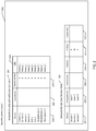
- Fig. 2 illustrates the exemplary database 200 architecture for the security control system 105.
- the security control system database 200 includes the network security devices table 201 and the network mobile user devices table 206 among others.
- the network security and safety devices table 201 stores the status, location, and URL of all the security and safety devices in the network security system 100. When new security and safety devices are installed on the network security system 100, the network security and safety devices table 201 is updated to reflect the addition.
- the network security and safety devices table 201 includes columns for the device name 202, device coordinates 203, device alarm condition 204, and the URL 205 among others.
- the security and safety device name column 202 stores a unique name for each security and safety device in the network security system 100.
- the security and safety device coordinates column 203 stores the position information of each device in the network security system 100.
- Types of position information include coordinates (e.g., longitude-latitude pairs) or logical references (e.g., a specific room in a building).
- the position information is static and determined at the time of installation; but, for mobile security devices 108, the position information is dynamic and updated based on position information sent by the device.
- the security and safety device alarm condition column 204 stores a flag representing whether or not specific security or safety devices raised alarm conditions in response to a security event.
- the security and safety device URL column 205 stores the reference or URL to the image data that is transmitted to the mobile user devices 113 in response to alarm conditions to thereby allow accessing of the image data via the NVR 103.
- the network mobile user devices table 206 monitors the status, location, and address of all mobile user devices 113 in the network security system 100.
- the network mobile user devices table includes columns for the device's name 207, the assigned user 208, coordinates 209, contact address 210, whether or not the user of the device is on duty 211, and the capabilities of the user 212 among others.
- the user device name column 207 stores a unique name for each mobile user device 113 in the network security system 100.
- the assigned user column 208 stores the name or other identifier of the security guard 114 in possession of each mobile user device 113 in the network security system 100.
- the user device coordinates column 209 stores the position information of each mobile user device 113 in the network security system 100.
- the user device address column 210 stores the contact address of each mobile user device 113 in the network security system 100.
- the address may be an IP address, a phone number, or any other identifier used to contact a mobile user device 113.
- the user device on duty column 211 stores a flag representing whether or not the mobile user device 113 is in use at the time. For example, while a security guard named John is on duty, his mobile user device 113 is able to receive notification of security events in his vicinity; however, when John's shift is over, he may not want his mobile user device 113 to be notified even if he is in the vicinity of security events.
- the user device on duty column 211 enables the dispatch service 106 to ignore John's mobile user device 113 when it determines which mobile user devices 113 to notify of security events.
- the user device capabilities column 212 stores information specifying the abilities of security guards 114 to respond to particular security events. For instance, if a subject is fleeing the scene of a crime in a car, the dispatch service 106 does not notify an unarmed security guard 114 who is on foot, even if he is proximity to the car, because he is incapable of adequately responding to the event. In a different scenario, the dispatch service 106 contacts a security guard 114 who is in a car if he can respond to the security event faster than a security guard 114 who is on foot, even if the security guard 114 on foot is closer to the event.
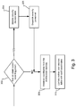
- Fig. 3 is a flow diagram illustrating the operation of the security control system 105 to check for alarm conditions and to track mobile user devices 113.
- the security control system 105 determines whether or not alarm conditions have been triggered according to step 302.
- the security control system 105 updates the network security and safety devices table 201 so that the alarm condition column 204 shows that the security or safety device observed a security event according to step 304.
- the security control system 105 calls the dispatch service 106, which transmits the notification to the one or more security guards 114 according to step 306.
- the security control system 105 retrieves the position information from the mobile user devices 113 in the field according to step 308. The security control system 105 then updates the coordinates column 209 of the network mobile user devices table 206 with said position information according to step 310. Once step 310 is complete, the security control system 105 transitions back to step 302 and queries the network security system 100 to determine if one or more alarm conditions have been triggered.
- Fig. 4 is a flow diagram illustrating the operation of the dispatch service 106 when the position information of the security and safety devices is used to alert mobile user devices 113 of alarm conditions according to step 306.
- the dispatch service 106 extracts the position information of the image data or device that raised the alarm conditions.
- An alarm condition is raised based on image data when the video analytics system 104 determines that the image data depicts a security event occurring.
- the position information of the image data is derived from the position information of its associated security camera 107.
- the location of the alarm condition is determined by reference to the network and safety device table 201.
- the dispatch service 106 determines if one or more security cameras 107 are associated with the image data or device that raised the alarm conditions according to step 404.
- the dispatch service 106 queries the network security and safety device table 201 for the URL 205 of the security camera or cameras 107 according to step 406.
- the dispatch service 106 searches for those security cameras 107 with position information proximate to the position information of the image data or device that raised the alarm conditions according to step 408. According to step 410, the dispatch service 106 retrieves the position information of the all mobile user devices 113 from the network mobile user devices table 206. Then, the dispatch service 106 gets only those mobile user devices 113 that are within a predetermined radius of the image data or device that raised the alarm conditions according to step 412. Lastly, the dispatch service 106 pushes the notification to only those mobile user devices 113 within the radius according to step 414.
- the notification preferably include a reference or URL of the security cameras that are associated with the device that raised the alarm condition and/or are proximate to the device that raised the alarm condition.
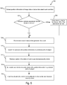
- Fig. 5 is a flow diagram illustrating the operation of the dispatch service 106 when a predicted path of a subject is used to alert mobile user devices 113 of alarm conditions according to step 306.
- the dispatch service 106 extracts the position information of the image data or device that raised the alarm conditions.
- the dispatch service 106 determines if one or more security cameras 107 are associated with the image data or device that raised the alarm conditions according to step 504.
- the dispatch service 106 queries the network security and safety device table 201 for the URL 205 of the security camera or cameras 107 according to step 506.
- the dispatch service 106 predicts the movement of the subject that generated the security event according to step 508.
- the dispatch service 106 searches for those security cameras 107 with position information proximate to the predicted path of the subject.
- the dispatch service 106 retrieves the position information of the all mobile user devices 113 from the network mobile user devices table 206. Then, the dispatch service 106 gets only those mobile user devices 113 that are most proximate to the predicted path of the subject according to step 514.
- the dispatch service 106 pushes the URL 205 and/or the notification to only those mobile user devices 113 most proximate to the predicted path of the subject according to step 516.
- Fig. 6 illustrates the physical components of a mobile user device 113.
- the mobile user device 113 is comprised of a positioning system 602 that generates position information for the mobile user device 113, wireless antenna 603, video display unit 604, and central processing unit (CPU) 605 among others.
- a positioning system 602 that generates position information for the mobile user device 113
- wireless antenna 603, video display unit 604, and central processing unit (CPU) 605 among others.
- the positioning system 602 determines the position information of the mobile user device 113 via satellite, radio triangulation, or other similar means.
- the position information is transmitted to the security control system 105 in order to update the coordinates column 209 of the network mobile user devices table 206.
- the wireless antenna 603 enables the mobile user device 113 to transmit data via wireless or cellular networks.
- the video display unit 604 is a screen that enables the mobile user device 113 to display image data and user interfaces to security guards 114.
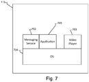
- Fig. 7 illustrates the software components of a mobile user device 113.
- the mobile user device 113 is comprised of a messaging service 702, a video player 703, an operating system 704, and a software application 705 among other software components.
- the messaging service 702 enables the mobile user device 113 to generate, communicate, receive, and interpret standard format messages transmitted to and from the security control system 105 and dispatch service 106.
- the video player 703 enables the mobile user device 113 to retrieve and display live image data transmitted from the dispatch service 106 during a security event.
- the software application 705 is responsible for controlling the communication between the mobile user device 113 and the security control system 105.
- the application 705 calls the messaging service 702 when it decides to transmit a message (e.g., when updating the mobile user device's 113 location in the network mobile user devices table 206) and calls the video player 703 when the security guards 114 attempts to retrieve the image data.
- Fig. 8 is a flow diagram illustrating the initialization and operation of a software application 705 on a mobile user device 113. According to step 802, the application 705 is launched. The user attempts to log in according to step 804.
- the application 705 determines if the login attempt is successful according to step 806.
- the application 705 transmits a message to the security control system 105 to add the mobile user device 113 to the network mobile user devices table 206 according to step 808.
- step 810 the application 705 later sends updated position information to the security control system 105, which then updates the coordinates column 209 in the network mobile user devices table 206.
- step 812 If the application 705 receives a dispatch message according to step 812, it displays said message to the user and play a sound according to step 814.
- the application 705 receives one or more URLs according to step 816, then it accesses and plays the one or more associated sets of image data using the video player 703 according to step 818.
Claims (14)
- Système de sécurité (100) comprenant :une ou plusieurs caméras de sécurité (107) qui capturent des données d'image ;un enregistreur vidéo de réseau (103) pour stocker et distribuer les données d'image provenant des caméras de sécurité ; etun système de commande de sécurité (105) qui reçoit des informations de position en provenance de dispositifs d'utilisateur mobiles (113), et fournit un accès aux données d'image au niveau des dispositifs d'utilisateur mobiles sur la base des informations de position par rapport aux emplacements des conditions d'alarme,caractérisé en ce quele système de commande de sécurité (105) détermine un trajet prédit d'un sujet qui a généré la condition d'alarme et fournit un accès aux données d'image au niveau des dispositifs d'utilisateur mobiles (113) sur la base des informations de position par rapport au trajet prédit du sujet.
- Système de sécurité (100) tel que revendiqué dans la revendication 1, dans lequel l'enregistreur vidéo de réseau (103) comporte un système d'analyse vidéo (104) qui analyse les données d'image provenant des caméras de sécurité (107) pour des événements de sécurité et génère les conditions d'alarme en réponse à la détection des événements de sécurité dans les données d'image.
- Système de sécurité (100) tel que revendiqué dans la revendication 2, dans lequel le système de commande de sécurité (105) détermine les emplacements des conditions d'alarme en accédant à des informations de position pour les caméras de sécurité (107) qui ont généré les données d'image qui ont déclenché les conditions d'alarme.
- Système de sécurité (100) tel que revendiqué dans l'une quelconque des revendications précédentes, dans lequel le système de commande de sécurité (105) surveille des dispositifs de sécurité et/ou de sûreté pour des conditions d'alarme et extrait des informations de position à partir des dispositifs de sécurité et/ou de sûreté qui ont généré les conditions d'alarme pour déterminer les emplacements des conditions d'alarme.
- Système de sécurité (100) tel que revendiqué dans l'une quelconque des revendications précédentes, dans lequel le système de commande de sécurité (105) comporte un service de répartition (106) qui distribue à un ou plusieurs dispositifs d'utilisateur mobiles (113) une référence aux données d'image en réponse aux conditions d'alarme en transmettant un message au ou aux plusieurs dispositifs d'utilisateur mobiles (113).
- Système de sécurité (100) tel que revendiqué dans la revendication 5, dans lequel le service de répartition distribue la référence en transmettant un message uniquement aux dispositifs d'utilisateur mobiles (113) qui se trouvent dans un rayon prédéterminé de la caméra de sécurité (107) ou des dispositifs de sécurité et/ou de sûreté qui ont déclenché les conditions d'alarme.
- Système de sécurité (100) tel que revendiqué dans l'une quelconque des revendications précédentes, comportant en outre un ou plusieurs dispositifs à boutons d'alerte mobiles qui permettent aux utilisateurs de générer sélectivement une condition d'alarme, et l'emplacement de la condition d'alarme est basé sur des informations de position pour les dispositifs à boutons d'alerte mobiles.
- Système de sécurité (100) tel que revendiqué dans l'une quelconque des revendications précédentes, dans lequel les dispositifs d'utilisateur mobiles (113) déterminent leurs emplacements respectifs et transmettent périodiquement les informations de position au système de commande de sécurité (105).
- Procédé de distribution de données d'image de sécurité, comprenant les étapes consistant à :capturer des données d'image ;recevoir des informations de position en provenance de dispositifs d'utilisateur mobiles (113) ;fournir un accès aux données d'image au niveau des dispositifs d'utilisateur mobiles (133) sur la base des informations de position par rapport aux emplacements des conditions d'alarme ; caractérisé par l'étape consistant àdéterminer un trajet prédit d'un sujet qui a généré la condition d'alarme et fournir un accès aux données d'image au niveau des dispositifs d'utilisateur mobiles (113) sur la base des informations de position par rapport au trajet prédit du sujet.
- Procédé selon la revendication 9, comprenant en outre l'analyse des données d'image pour des événements de sécurité et la génération des conditions d'alarme en réponse à la détection des événements de sécurité.
- Procédé selon l'une quelconque des revendications 9 et 10, comprenant en outre la détermination des emplacements des conditions d'alarme en accédant à des informations de position pour une caméra de sécurité qui a capturé les données d'image.
- Procédé selon l'une quelconque des revendications 9 à 11, comprenant en outre la surveillance de dispositifs de sécurité et/ou de sûreté pour des conditions d'alarme et l'extraction d'informations de position à partir des dispositifs de sécurité et/ou de sûreté qui ont généré les conditions d'alarme pour déterminer les emplacements des conditions d'alarme.
- Procédé selon l'une quelconque des revendications 9 à 12, comprenant en outre la distribution, à un ou plusieurs dispositifs d'utilisateur mobiles (113), d'une référence aux données d'image en réponse aux conditions d'alarme en transmettant un message au ou aux plusieurs dispositifs d'utilisateur mobiles (113).
- Procédé selon l'une quelconque des revendications 9 à 13, comprenant en outre la distribution, à un ou plusieurs dispositifs d'utilisateur mobiles (113), d'une référence aux données d'image en réponse aux conditions d'alarme en transmettant un message uniquement aux dispositifs d'utilisateur mobiles qui se trouvent dans un rayon prédéterminé de la caméra de sécurité (107) ou des dispositifs de sécurité et/ou de sûreté qui ont déclenché les conditions d'alarme.
Applications Claiming Priority (2)
| Application Number | Priority Date | Filing Date | Title |
|---|---|---|---|
| US13/965,833 US10482738B2 (en) | 2013-08-13 | 2013-08-13 | System and method for video/audio and event dispatch using positioning system |
| PCT/US2014/047742 WO2015023405A1 (fr) | 2013-08-13 | 2014-07-23 | Système et procédé pour le déploiement d'audio/vidéo et d'événements au moyen d'un système de positionnement |
Publications (2)
| Publication Number | Publication Date |
|---|---|
| EP3033742A1 EP3033742A1 (fr) | 2016-06-22 |
| EP3033742B1 true EP3033742B1 (fr) | 2019-06-26 |
Family
ID=51355626
Family Applications (1)
| Application Number | Title | Priority Date | Filing Date |
|---|---|---|---|
| EP14752470.6A Not-in-force EP3033742B1 (fr) | 2013-08-13 | 2014-07-23 | Système et procédé pour le déploiement d'audio/vidéo et d'événements au moyen d'un système de positionnement |
Country Status (3)
| Country | Link |
|---|---|
| US (1) | US10482738B2 (fr) |
| EP (1) | EP3033742B1 (fr) |
| WO (1) | WO2015023405A1 (fr) |
Families Citing this family (19)
| Publication number | Priority date | Publication date | Assignee | Title |
|---|---|---|---|---|
| US20150146002A1 (en) * | 2013-11-26 | 2015-05-28 | David Cruz | Door with security features and integrated system |
| US10290067B1 (en) | 2014-06-05 | 2019-05-14 | ProSports Technologies, LLC | Wireless concession delivery |
| US9965938B1 (en) | 2014-07-11 | 2018-05-08 | ProSports Technologies, LLC | Restroom queue management |
| US9892371B1 (en) | 2014-07-28 | 2018-02-13 | ProSports Technologies, LLC | Queue information transmission |
| US9607497B1 (en) * | 2014-08-25 | 2017-03-28 | ProSports Technologies, LLC | Wireless communication security system |
| KR102174839B1 (ko) * | 2014-12-26 | 2020-11-05 | 삼성전자주식회사 | 보안 시스템 및 그 운영 방법 및 장치 |
| IL236752B (en) | 2015-01-15 | 2019-10-31 | Eran Jedwab | Integrated security method and system |
| CN104867263B (zh) * | 2015-05-15 | 2017-08-08 | 深圳市万物联有限公司 | 摄像头定位报警方法及系统 |
| WO2016198814A1 (fr) * | 2015-06-12 | 2016-12-15 | Engie | Capteurs et alarmes de gestion multi-services d'un batiment et d'equipements a l'usage des occupants |
| FR3037430A1 (fr) * | 2015-06-12 | 2016-12-16 | Gdf Suez | Capteurs et alarmes de gestion technique d'un batiment et d'equipements a l'usage des occupants |
| WO2017048115A1 (fr) * | 2015-09-18 | 2017-03-23 | Kian Vui Lo | Système de caméra vidéo intelligent en temps réel |
| US10382729B2 (en) | 2016-01-06 | 2019-08-13 | Vivint, Inc. | Home automation system-initiated calls |
| US10271012B2 (en) | 2016-01-06 | 2019-04-23 | Vivint, Inc. | Home automation system-initiated calls |
| CN106060474A (zh) * | 2016-06-27 | 2016-10-26 | 深圳辉锐天眼科技有限公司 | 一种对传统视频监控升级为视频预警系统的方法 |
| EP3839821A3 (fr) | 2016-10-25 | 2021-09-15 | Owl Cameras, Inc. | Configuration de collecte de données vidéo, de capture d'image et d'analyse |
| US10475311B2 (en) | 2017-03-20 | 2019-11-12 | Amazon Technologies, Inc. | Dynamic assessment using an audio/video recording and communication device |
| CN110390820A (zh) * | 2018-04-18 | 2019-10-29 | 光宝电子(广州)有限公司 | 路况信息提供系统及路况信息提供方法 |
| CA3136341A1 (fr) * | 2019-05-02 | 2020-11-05 | Patricia Monica THOMPSON | Systeme de securite et procedes de fonctionnement |
| US11941964B2 (en) * | 2022-06-15 | 2024-03-26 | International Business Machines Corporation | Safety violation detection |
Family Cites Families (23)
| Publication number | Priority date | Publication date | Assignee | Title |
|---|---|---|---|---|
| US7397371B2 (en) * | 2005-01-31 | 2008-07-08 | Honeywell International Inc. | Security system access control and method |
| GB2441929B (en) | 2005-09-12 | 2010-08-18 | Ericsson Telefon Ab L M | A mobile security monitoring method and system and an alarm security node in the system |
| US7956735B2 (en) | 2006-05-15 | 2011-06-07 | Cernium Corporation | Automated, remotely-verified alarm system with intrusion and video surveillance and digital video recording |
| US20090091620A1 (en) * | 2007-10-05 | 2009-04-09 | Anderson Leroy E | Electronic security system |
| US8345097B2 (en) * | 2008-02-15 | 2013-01-01 | Harris Corporation | Hybrid remote digital recording and acquisition system |
| US7903143B2 (en) * | 2008-03-13 | 2011-03-08 | Dell Products L.P. | Systems and methods for document scanning using a variable intensity display of an information handling system |
| US20110267462A1 (en) * | 2010-04-29 | 2011-11-03 | Fred Cheng | Versatile remote video monitoring through the internet |
| KR101149329B1 (ko) * | 2010-06-30 | 2012-05-23 | 아주대학교산학협력단 | 감시카메라를 이용한 능동적 객체 추적 장치 및 방법 |
| US20120136559A1 (en) * | 2010-11-29 | 2012-05-31 | Reagan Inventions, Llc | Device and system for identifying emergency vehicles and broadcasting the information |
| US8489065B2 (en) * | 2011-05-03 | 2013-07-16 | Robert M Green | Mobile device controller application for any security system |
| CA2836128A1 (fr) * | 2011-05-13 | 2012-11-22 | Tattletale Portable Alarm Systems, Inc. | Alarme destinee aux clients et munie d'un bouton silence |
| US9081992B2 (en) * | 2011-09-16 | 2015-07-14 | The Intervention Science Fund I, LLC | Confirming that an image includes at least a portion of a target region of interest |
| US8494481B1 (en) | 2011-11-02 | 2013-07-23 | Amazon Technologies, Inc. | Mobile alarm device |
| US20130135467A1 (en) * | 2011-11-30 | 2013-05-30 | Honeywell International Inc. | System and Method to Automatically Begin a Video Chat Session |
| US10769913B2 (en) | 2011-12-22 | 2020-09-08 | Pelco, Inc. | Cloud-based video surveillance management system |
| WO2014036255A1 (fr) * | 2012-08-30 | 2014-03-06 | Numerex Corp. | Capteur d'alarme prenant en charge une communication sans fil à longue distance |
| US20140071283A1 (en) * | 2012-09-07 | 2014-03-13 | Khan Ali Yousafi | Identification system |
| US8819855B2 (en) * | 2012-09-10 | 2014-08-26 | Mdi Security, Llc | System and method for deploying handheld devices to secure an area |
| US9787947B2 (en) * | 2013-03-13 | 2017-10-10 | Pelco, Inc. | Surveillance system with intelligently interchangeable cameras |
| US9485472B2 (en) * | 2013-05-13 | 2016-11-01 | Honeywell International Inc. | System and method for enhanced privacy, resource and alert management |
| US8823795B1 (en) * | 2013-07-26 | 2014-09-02 | SkyBell Technologies, Inc. | Doorbell communication systems and methods |
| JP6234110B2 (ja) * | 2013-08-12 | 2017-11-22 | 株式会社キーエンス | 画像処理センサシステム |
| IL236752B (en) * | 2015-01-15 | 2019-10-31 | Eran Jedwab | Integrated security method and system |
-
2013
- 2013-08-13 US US13/965,833 patent/US10482738B2/en active Active
-
2014
- 2014-07-23 WO PCT/US2014/047742 patent/WO2015023405A1/fr active Application Filing
- 2014-07-23 EP EP14752470.6A patent/EP3033742B1/fr not_active Not-in-force
Non-Patent Citations (1)
| Title |
|---|
| None * |
Also Published As
| Publication number | Publication date |
|---|---|
| US20150049190A1 (en) | 2015-02-19 |
| US10482738B2 (en) | 2019-11-19 |
| WO2015023405A1 (fr) | 2015-02-19 |
| EP3033742A1 (fr) | 2016-06-22 |
Similar Documents
| Publication | Publication Date | Title |
|---|---|---|
| EP3033742B1 (fr) | Système et procédé pour le déploiement d'audio/vidéo et d'événements au moyen d'un système de positionnement | |
| US11527149B2 (en) | Emergency alert system | |
| US8630820B2 (en) | Methods and systems for threat assessment, safety management, and monitoring of individuals and groups | |
| EP3118826B1 (fr) | Système de surveillance, de sécurité de maison, de bureau par micro-drones mobiles et caméras ip | |
| US9418537B2 (en) | Mobile computing device including personal security system | |
| US10854058B2 (en) | Emergency alert system | |
| US20170188216A1 (en) | Personal emergency saver system and method | |
| US20140118140A1 (en) | Methods and systems for requesting the aid of security volunteers using a security network | |
| EP2815389B1 (fr) | Systèmes et procédés pour la fourniture de ressources d'urgence | |
| KR100982398B1 (ko) | ZigBee와 CCTV를 이용한 상황관제 시스템과 어린이보호 시스템 | |
| US10142814B2 (en) | Emergency communication system and methods therefor | |
| US11854357B2 (en) | Object tracking using disparate monitoring systems | |
| WO2019052021A1 (fr) | Procédé d'alarme, procédé de traitement d'alarme, dispositif électronique et support d'enregistrement informatique | |
| US20140120977A1 (en) | Methods and systems for providing multiple coordinated safety responses | |
| US11749094B2 (en) | Apparatus, systems and methods for providing alarm and sensor data to emergency networks | |
| US10650651B1 (en) | Automated geospatial security event grouping | |
| JP2014044641A (ja) | 犯罪情報管理装置および犯罪情報管理システム | |
| US20130258110A1 (en) | System and Method for Providing Security on Demand | |
| US11263881B2 (en) | System and method of alternative tracking upon disabling of monitoring device | |
| KR101383583B1 (ko) | 사건 현장에 대한 원격 감시 방법, 원격 감시 시스템의 운용 방법 및 모바일 단말기에서 구동되는 어플리케이션의 원격 감시 구현 방법 | |
| KR20100013470A (ko) | Rf 태그를 이용한 원격 감시 서버, 시스템, 및 그 방법 | |
| JP7412155B2 (ja) | 監視装置、監視システム、プログラムおよび侵入者特定情報取得方法 | |
| Ahiara et al. | An Internet of Things (IoT) Based Neighbourhood Distress Alert System | |
| JP2005215961A (ja) | 徘徊者離院防止システム |
Legal Events
| Date | Code | Title | Description |
|---|---|---|---|
| PUAI | Public reference made under article 153(3) epc to a published international application that has entered the european phase |
Free format text: ORIGINAL CODE: 0009012 |
|
| 17P | Request for examination filed |
Effective date: 20160224 |
|
| AK | Designated contracting states |
Kind code of ref document: A1 Designated state(s): AL AT BE BG CH CY CZ DE DK EE ES FI FR GB GR HR HU IE IS IT LI LT LU LV MC MK MT NL NO PL PT RO RS SE SI SK SM TR |
|
| AX | Request for extension of the european patent |
Extension state: BA ME |
|
| DAX | Request for extension of the european patent (deleted) | ||
| STAA | Information on the status of an ep patent application or granted ep patent |
Free format text: STATUS: EXAMINATION IS IN PROGRESS |
|
| 17Q | First examination report despatched |
Effective date: 20180801 |
|
| GRAP | Despatch of communication of intention to grant a patent |
Free format text: ORIGINAL CODE: EPIDOSNIGR1 |
|
| STAA | Information on the status of an ep patent application or granted ep patent |
Free format text: STATUS: GRANT OF PATENT IS INTENDED |
|
| INTG | Intention to grant announced |
Effective date: 20190128 |
|
| GRAS | Grant fee paid |
Free format text: ORIGINAL CODE: EPIDOSNIGR3 |
|
| GRAA | (expected) grant |
Free format text: ORIGINAL CODE: 0009210 |
|
| STAA | Information on the status of an ep patent application or granted ep patent |
Free format text: STATUS: THE PATENT HAS BEEN GRANTED |
|
| AK | Designated contracting states |
Kind code of ref document: B1 Designated state(s): AL AT BE BG CH CY CZ DE DK EE ES FI FR GB GR HR HU IE IS IT LI LT LU LV MC MK MT NL NO PL PT RO RS SE SI SK SM TR |
|
| REG | Reference to a national code |
Ref country code: GB Ref legal event code: FG4D |
|
| REG | Reference to a national code |
Ref country code: CH Ref legal event code: EP |
|
| REG | Reference to a national code |
Ref country code: AT Ref legal event code: REF Ref document number: 1149211 Country of ref document: AT Kind code of ref document: T Effective date: 20190715 |
|
| REG | Reference to a national code |
Ref country code: DE Ref legal event code: R096 Ref document number: 602014049095 Country of ref document: DE |
|
| REG | Reference to a national code |
Ref country code: IE Ref legal event code: FG4D |
|
| REG | Reference to a national code |
Ref country code: NL Ref legal event code: MP Effective date: 20190626 |
|
| PG25 | Lapsed in a contracting state [announced via postgrant information from national office to epo] |
Ref country code: AL Free format text: LAPSE BECAUSE OF FAILURE TO SUBMIT A TRANSLATION OF THE DESCRIPTION OR TO PAY THE FEE WITHIN THE PRESCRIBED TIME-LIMIT Effective date: 20190626 Ref country code: NO Free format text: LAPSE BECAUSE OF FAILURE TO SUBMIT A TRANSLATION OF THE DESCRIPTION OR TO PAY THE FEE WITHIN THE PRESCRIBED TIME-LIMIT Effective date: 20190926 Ref country code: HR Free format text: LAPSE BECAUSE OF FAILURE TO SUBMIT A TRANSLATION OF THE DESCRIPTION OR TO PAY THE FEE WITHIN THE PRESCRIBED TIME-LIMIT Effective date: 20190626 Ref country code: LT Free format text: LAPSE BECAUSE OF FAILURE TO SUBMIT A TRANSLATION OF THE DESCRIPTION OR TO PAY THE FEE WITHIN THE PRESCRIBED TIME-LIMIT Effective date: 20190626 Ref country code: SE Free format text: LAPSE BECAUSE OF FAILURE TO SUBMIT A TRANSLATION OF THE DESCRIPTION OR TO PAY THE FEE WITHIN THE PRESCRIBED TIME-LIMIT Effective date: 20190626 Ref country code: FI Free format text: LAPSE BECAUSE OF FAILURE TO SUBMIT A TRANSLATION OF THE DESCRIPTION OR TO PAY THE FEE WITHIN THE PRESCRIBED TIME-LIMIT Effective date: 20190626 |
|
| REG | Reference to a national code |
Ref country code: LT Ref legal event code: MG4D |
|
| PG25 | Lapsed in a contracting state [announced via postgrant information from national office to epo] |
Ref country code: LV Free format text: LAPSE BECAUSE OF FAILURE TO SUBMIT A TRANSLATION OF THE DESCRIPTION OR TO PAY THE FEE WITHIN THE PRESCRIBED TIME-LIMIT Effective date: 20190626 Ref country code: RS Free format text: LAPSE BECAUSE OF FAILURE TO SUBMIT A TRANSLATION OF THE DESCRIPTION OR TO PAY THE FEE WITHIN THE PRESCRIBED TIME-LIMIT Effective date: 20190626 Ref country code: BG Free format text: LAPSE BECAUSE OF FAILURE TO SUBMIT A TRANSLATION OF THE DESCRIPTION OR TO PAY THE FEE WITHIN THE PRESCRIBED TIME-LIMIT Effective date: 20190926 Ref country code: GR Free format text: LAPSE BECAUSE OF FAILURE TO SUBMIT A TRANSLATION OF THE DESCRIPTION OR TO PAY THE FEE WITHIN THE PRESCRIBED TIME-LIMIT Effective date: 20190927 |
|
| REG | Reference to a national code |
Ref country code: AT Ref legal event code: MK05 Ref document number: 1149211 Country of ref document: AT Kind code of ref document: T Effective date: 20190626 |
|
| PG25 | Lapsed in a contracting state [announced via postgrant information from national office to epo] |
Ref country code: PT Free format text: LAPSE BECAUSE OF FAILURE TO SUBMIT A TRANSLATION OF THE DESCRIPTION OR TO PAY THE FEE WITHIN THE PRESCRIBED TIME-LIMIT Effective date: 20191028 Ref country code: SK Free format text: LAPSE BECAUSE OF FAILURE TO SUBMIT A TRANSLATION OF THE DESCRIPTION OR TO PAY THE FEE WITHIN THE PRESCRIBED TIME-LIMIT Effective date: 20190626 Ref country code: EE Free format text: LAPSE BECAUSE OF FAILURE TO SUBMIT A TRANSLATION OF THE DESCRIPTION OR TO PAY THE FEE WITHIN THE PRESCRIBED TIME-LIMIT Effective date: 20190626 Ref country code: AT Free format text: LAPSE BECAUSE OF FAILURE TO SUBMIT A TRANSLATION OF THE DESCRIPTION OR TO PAY THE FEE WITHIN THE PRESCRIBED TIME-LIMIT Effective date: 20190626 Ref country code: NL Free format text: LAPSE BECAUSE OF FAILURE TO SUBMIT A TRANSLATION OF THE DESCRIPTION OR TO PAY THE FEE WITHIN THE PRESCRIBED TIME-LIMIT Effective date: 20190626 Ref country code: CZ Free format text: LAPSE BECAUSE OF FAILURE TO SUBMIT A TRANSLATION OF THE DESCRIPTION OR TO PAY THE FEE WITHIN THE PRESCRIBED TIME-LIMIT Effective date: 20190626 Ref country code: RO Free format text: LAPSE BECAUSE OF FAILURE TO SUBMIT A TRANSLATION OF THE DESCRIPTION OR TO PAY THE FEE WITHIN THE PRESCRIBED TIME-LIMIT Effective date: 20190626 |
|
| REG | Reference to a national code |
Ref country code: DE Ref legal event code: R119 Ref document number: 602014049095 Country of ref document: DE |
|
| PG25 | Lapsed in a contracting state [announced via postgrant information from national office to epo] |
Ref country code: ES Free format text: LAPSE BECAUSE OF FAILURE TO SUBMIT A TRANSLATION OF THE DESCRIPTION OR TO PAY THE FEE WITHIN THE PRESCRIBED TIME-LIMIT Effective date: 20190626 Ref country code: IT Free format text: LAPSE BECAUSE OF FAILURE TO SUBMIT A TRANSLATION OF THE DESCRIPTION OR TO PAY THE FEE WITHIN THE PRESCRIBED TIME-LIMIT Effective date: 20190626 Ref country code: IS Free format text: LAPSE BECAUSE OF FAILURE TO SUBMIT A TRANSLATION OF THE DESCRIPTION OR TO PAY THE FEE WITHIN THE PRESCRIBED TIME-LIMIT Effective date: 20191026 Ref country code: SM Free format text: LAPSE BECAUSE OF FAILURE TO SUBMIT A TRANSLATION OF THE DESCRIPTION OR TO PAY THE FEE WITHIN THE PRESCRIBED TIME-LIMIT Effective date: 20190626 |
|
| REG | Reference to a national code |
Ref country code: CH Ref legal event code: PL |
|
| PG25 | Lapsed in a contracting state [announced via postgrant information from national office to epo] |
Ref country code: MC Free format text: LAPSE BECAUSE OF FAILURE TO SUBMIT A TRANSLATION OF THE DESCRIPTION OR TO PAY THE FEE WITHIN THE PRESCRIBED TIME-LIMIT Effective date: 20190626 Ref country code: TR Free format text: LAPSE BECAUSE OF FAILURE TO SUBMIT A TRANSLATION OF THE DESCRIPTION OR TO PAY THE FEE WITHIN THE PRESCRIBED TIME-LIMIT Effective date: 20190626 |
|
| REG | Reference to a national code |
Ref country code: BE Ref legal event code: MM Effective date: 20190731 |
|
| PG25 | Lapsed in a contracting state [announced via postgrant information from national office to epo] |
Ref country code: PL Free format text: LAPSE BECAUSE OF FAILURE TO SUBMIT A TRANSLATION OF THE DESCRIPTION OR TO PAY THE FEE WITHIN THE PRESCRIBED TIME-LIMIT Effective date: 20190626 Ref country code: DE Free format text: LAPSE BECAUSE OF NON-PAYMENT OF DUE FEES Effective date: 20200201 Ref country code: DK Free format text: LAPSE BECAUSE OF FAILURE TO SUBMIT A TRANSLATION OF THE DESCRIPTION OR TO PAY THE FEE WITHIN THE PRESCRIBED TIME-LIMIT Effective date: 20190626 |
|
| PG25 | Lapsed in a contracting state [announced via postgrant information from national office to epo] |
Ref country code: LU Free format text: LAPSE BECAUSE OF NON-PAYMENT OF DUE FEES Effective date: 20190723 Ref country code: BE Free format text: LAPSE BECAUSE OF NON-PAYMENT OF DUE FEES Effective date: 20190731 Ref country code: LI Free format text: LAPSE BECAUSE OF NON-PAYMENT OF DUE FEES Effective date: 20190731 Ref country code: IS Free format text: LAPSE BECAUSE OF FAILURE TO SUBMIT A TRANSLATION OF THE DESCRIPTION OR TO PAY THE FEE WITHIN THE PRESCRIBED TIME-LIMIT Effective date: 20200224 Ref country code: CH Free format text: LAPSE BECAUSE OF NON-PAYMENT OF DUE FEES Effective date: 20190731 |
|
| PLBE | No opposition filed within time limit |
Free format text: ORIGINAL CODE: 0009261 |
|
| STAA | Information on the status of an ep patent application or granted ep patent |
Free format text: STATUS: NO OPPOSITION FILED WITHIN TIME LIMIT |
|
| PG2D | Information on lapse in contracting state deleted |
Ref country code: IS |
|
| PG25 | Lapsed in a contracting state [announced via postgrant information from national office to epo] |
Ref country code: IE Free format text: LAPSE BECAUSE OF NON-PAYMENT OF DUE FEES Effective date: 20190723 Ref country code: FR Free format text: LAPSE BECAUSE OF NON-PAYMENT OF DUE FEES Effective date: 20190826 |
|
| 26N | No opposition filed |
Effective date: 20200603 |
|
| PG25 | Lapsed in a contracting state [announced via postgrant information from national office to epo] |
Ref country code: SI Free format text: LAPSE BECAUSE OF FAILURE TO SUBMIT A TRANSLATION OF THE DESCRIPTION OR TO PAY THE FEE WITHIN THE PRESCRIBED TIME-LIMIT Effective date: 20190626 |
|
| GBPC | Gb: european patent ceased through non-payment of renewal fee |
Effective date: 20190926 |
|
| PG25 | Lapsed in a contracting state [announced via postgrant information from national office to epo] |
Ref country code: GB Free format text: LAPSE BECAUSE OF NON-PAYMENT OF DUE FEES Effective date: 20190926 |
|
| PG25 | Lapsed in a contracting state [announced via postgrant information from national office to epo] |
Ref country code: CY Free format text: LAPSE BECAUSE OF FAILURE TO SUBMIT A TRANSLATION OF THE DESCRIPTION OR TO PAY THE FEE WITHIN THE PRESCRIBED TIME-LIMIT Effective date: 20190626 |
|
| PG25 | Lapsed in a contracting state [announced via postgrant information from national office to epo] |
Ref country code: HU Free format text: LAPSE BECAUSE OF FAILURE TO SUBMIT A TRANSLATION OF THE DESCRIPTION OR TO PAY THE FEE WITHIN THE PRESCRIBED TIME-LIMIT; INVALID AB INITIO Effective date: 20140723 Ref country code: MT Free format text: LAPSE BECAUSE OF FAILURE TO SUBMIT A TRANSLATION OF THE DESCRIPTION OR TO PAY THE FEE WITHIN THE PRESCRIBED TIME-LIMIT Effective date: 20190626 |
|
| PG25 | Lapsed in a contracting state [announced via postgrant information from national office to epo] |
Ref country code: MK Free format text: LAPSE BECAUSE OF FAILURE TO SUBMIT A TRANSLATION OF THE DESCRIPTION OR TO PAY THE FEE WITHIN THE PRESCRIBED TIME-LIMIT Effective date: 20190626 |