EP3033517B1 - Filtre à liquide,notamment filtre a carburant - Google Patents
Filtre à liquide,notamment filtre a carburant Download PDFInfo
- Publication number
- EP3033517B1 EP3033517B1 EP14744798.1A EP14744798A EP3033517B1 EP 3033517 B1 EP3033517 B1 EP 3033517B1 EP 14744798 A EP14744798 A EP 14744798A EP 3033517 B1 EP3033517 B1 EP 3033517B1
- Authority
- EP
- European Patent Office
- Prior art keywords
- valve body
- fuel
- oil filter
- channel
- housing
- Prior art date
- Legal status (The legal status is an assumption and is not a legal conclusion. Google has not performed a legal analysis and makes no representation as to the accuracy of the status listed.)
- Active
Links
- 239000007788 liquid Substances 0.000 title claims description 39
- 239000000446 fuel Substances 0.000 title claims description 24
- 238000009423 ventilation Methods 0.000 claims description 57
- 238000007599 discharging Methods 0.000 claims 1
- XLYOFNOQVPJJNP-UHFFFAOYSA-N water Substances O XLYOFNOQVPJJNP-UHFFFAOYSA-N 0.000 description 20
- 239000012530 fluid Substances 0.000 description 12
- 238000007789 sealing Methods 0.000 description 12
- 238000002485 combustion reaction Methods 0.000 description 3
- 238000010276 construction Methods 0.000 description 2
- XSQUKJJJFZCRTK-UHFFFAOYSA-N Urea Chemical compound NC(N)=O XSQUKJJJFZCRTK-UHFFFAOYSA-N 0.000 description 1
- 239000004202 carbamide Substances 0.000 description 1
- 230000001419 dependent effect Effects 0.000 description 1
- 238000011161 development Methods 0.000 description 1
- 230000018109 developmental process Effects 0.000 description 1
- 238000001914 filtration Methods 0.000 description 1
- 230000004941 influx Effects 0.000 description 1
- 230000010354 integration Effects 0.000 description 1
- 230000035515 penetration Effects 0.000 description 1
- 230000007704 transition Effects 0.000 description 1
- 238000011144 upstream manufacturing Methods 0.000 description 1
Images


Classifications
-
- B—PERFORMING OPERATIONS; TRANSPORTING
- B01—PHYSICAL OR CHEMICAL PROCESSES OR APPARATUS IN GENERAL
- B01D—SEPARATION
- B01D36/00—Filter circuits or combinations of filters with other separating devices
- B01D36/003—Filters in combination with devices for the removal of liquids
- B01D36/006—Purge means
-
- F—MECHANICAL ENGINEERING; LIGHTING; HEATING; WEAPONS; BLASTING
- F02—COMBUSTION ENGINES; HOT-GAS OR COMBUSTION-PRODUCT ENGINE PLANTS
- F02M—SUPPLYING COMBUSTION ENGINES IN GENERAL WITH COMBUSTIBLE MIXTURES OR CONSTITUENTS THEREOF
- F02M37/00—Apparatus or systems for feeding liquid fuel from storage containers to carburettors or fuel-injection apparatus; Arrangements for purifying liquid fuel specially adapted for, or arranged on, internal-combustion engines
- F02M37/22—Arrangements for purifying liquid fuel specially adapted for, or arranged on, internal-combustion engines, e.g. arrangements in the feeding system
- F02M37/24—Arrangements for purifying liquid fuel specially adapted for, or arranged on, internal-combustion engines, e.g. arrangements in the feeding system characterised by water separating means
Definitions
- the invention relates to a fuel or oil filter, according to the preamble of claim 1.
- a fuel filter which has in a housing an annular filter element, which is flowed through by the fuel radially from outside to inside.
- water droplets can be deposited, which flow down and are collected in a water collection chamber within the filter housing.
- a drain valve is integrated, through which the collected water can be discharged from the filter housing.
- the drain valve has a valve housing which can be screwed into the bottom of the housing and a valve body received in the valve housing via a further screw connection which opens or closes a drainage channel.
- the discharge channel extends within the valve housing and has a portion in the tubular valve body, through which the water can flow in the open state.
- a ventilation channel is provided in the valve housing, which communicates with the portion of the water discharge channel upstream of the valve body. As soon as the valve body is screwed on, the discharge channel and the ventilation channel are opened simultaneously.
- the invention has the object of reliably dissipating separated fluid from a fluid filter with structurally simple measures.
- the fuel or oil filter according to the invention is preferably used for internal combustion engines. However, it is also possible to filter other liquids, for example use as an oil filter or as a urea filter.
- water is separated, which accumulates within the filter housing in a liquid collecting space and can be discharged regularly via a drain valve.
- the discharge valve opens or closes a discharge channel, which is connected to the liquid collecting space and through which the water collected there can be discharged from the filter housing.
- the valve body is accommodated in a valve housing which is located in or on the filter housing or a component connected to the filter housing.
- the valve body is to be adjusted in the valve housing between a closed position and an open position, wherein in the open position, the discharge channel is open, so that water can be discharged from the water collecting space, whereas in the closed position, the discharge channel is closed.
- the fuel or oil filter has a ventilation channel through which air can flow into the liquid collecting space during the discharge of the water for pressure equalization.
- the ventilation channel is opened or closed by the valve body of the drain valve.
- the discharge channel and the ventilation channel are designed as separate channels and are opened at a time offset during the opening movement of the valve body. First, the discharge channel, then the ventilation channel is opened during the adjusting movement of the valve body. Due to the staggered opening of discharge and ventilation channel prevents fluid from the fluid collection chamber accidentally flows through the ventilation channel to the outside.
- fluid can begin to flow out of the fluid collection chamber via the first discharge channel, only then is the ventilation channel opened, wherein a pressure drop in the fluid collection chamber begins with the start of the outflow, which avoids fluid from the fluid collection chamber via the ventilation channel with the subsequent opening of the ventilation channel accidentally flows outwards.
- the negative pressure in the liquid collecting space rather ensures that air from the outside via the ventilation channel in the liquid collecting space reaches, so that a pressure equalization can take place and the further outflow can take place unhindered via the opened discharge channel.
- the discharge channel runs outside of the valve body.
- the adjusting movement of the valve body is preferably a linear, axial adjusting movement, which is achieved by screwing the valve body in the receiving valve housing. The resulting in the screw movement rotation about the valve body longitudinal axis moves the valve body axially and causes the opening and closing of the discharge channel, which, however, can be arranged stationary on the housing.
- the ventilation channel protrudes into the liquid collecting space, wherein the inflow opening of the ventilation channel in the liquid collecting space is higher than the inflow opening of the discharge channel in the liquid collecting space.
- This height difference in the inlet openings of ventilation and discharge channel provides additional security against accidental outflow of liquid through the ventilation channel to the outside. If the water level in the liquid collecting space below the inlet opening of the ventilation channel, a flow of water through the ventilation channel is excluded, provided that the liquid filter is in proper position and on a level surface.
- the higher inflow opening of the ventilation duct is usually located above the water level in the liquid collecting space even with the usual inclines or inclines.
- the discharge channel and the ventilation channel each extend at least in sections in the radial direction, relative to the Longitudinal axis of the valve body.
- the discharge channel and ventilation channel are located on diametrically opposite sides of the valve body and are arranged axially offset from one another. With the axial opening movement of the valve body, the discharge and the ventilation duct are opened one after the other.
- the radially extending sections are in this case designed as nozzles, which are preferably formed integrally with the valve housing.
- the radial port of the ventilation duct which protrudes into the liquid collecting space, communicates with a further portion of the ventilation channel between the inner wall of the valve housing and the outside of the valve body.
- an inflow opening of the discharge channel is introduced into the valve housing, via which it communicates with the liquid collecting space.
- the radial nozzle of the discharge channel extends outwards, if necessary, a hose can be attached to the nozzle.
- the drain valve is in a housing cover, which is to be connected to the housing of the liquid filter, for example, on the bottom of the housing can be screwed.
- the valve housing, in which the valve body is received is in this case either connected to the housing cover, for example also by screws, or is formed integrally with the housing cover.
- valve body is arranged radially to the housing longitudinal axis of the liquid filter. In this way, a small construction in the axial direction of the filter design can be achieved, also the integration of the drain valve in the housing cover of the liquid filter is possible.
- a sealing stopper may be arranged on the outside of the valve body, which rests in the closed position of the valve body on an associated counter-stop on the inside of the female valve housing and also the discharge channel from the ventilation channel separated flow-tight.
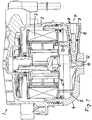
- a fuel filter 1 for an internal combustion engine is shown in a vehicle.
- the fuel filter 1 has in a filter housing 2 on an annular filter element 3, which is flowed through radially from outside to inside of the fluid to be cleaned.
- water droplets can be separated, which flow downwards and are collected in a liquid collecting space 5, which is formed in the housing cover 4.
- the water level of the water received in the liquid collecting space is designated by reference numeral 6.
- a drain valve 7 is integrated in the housing cover 4, which is formed separately from the filter housing 2 and is to be connected via a screw connection with the filter housing 2 at its bottom.
- the drain valve 7 has a valve housing 8 and a valve body 9 accommodated in the valve housing, wherein the valve housing is formed integrally with the housing cover 4.
- the longitudinal axis 11 of the drain valve 7 extends radially to the longitudinal axis 10 of the fuel filter.
- the valve body 9 is over a screw connected to the valve housing 8; On the outside is located on the valve body 9, an external thread which engages in a corresponding internal thread on the inner wall of the valve housing 8.
- valve body 9 During an actuating movement of the valve body 9, which is generated by a rotation of the valve body, the valve body 9 is displaced in the direction of its longitudinal axis 11 and opens or closes a discharge channel 12, via which the water 6 in the liquid collecting space 5 can be derived.
- a ventilation channel 13 can be opened or closed, can be passed through the air in the open state from the outside into the liquid collecting space 5 for pressure equalization during the outflow of water.
- valve body 9 of the drain valve 7 is shown in its closed position, in which both the discharge channel 12 and the ventilation channel 13 are closed.
- valve body 9 is shown in the open position, in which both channels 12, 13 are open.
- the discharge channel 12 has a radially directed to the longitudinal axis 11 of the drain valve 7, downwardly pointing nozzle, which communicates via an inflow opening 14 in the wall of the valve housing 8 with the liquid collecting space 5.
- the flow path between the inflow opening 14 and the downwardly projecting nozzle of the discharge channel 12 is interrupted.
- Adjacent to the free end face is located on the circumference of the valve body 9, a first sealing ring 15 which separates the flow path between the inflow opening 14 and the neck of the discharge channel 12 flow-tight.
- a first sealing ring 15 which separates the flow path between the inflow opening 14 and the neck of the discharge channel 12 flow-tight.
- valve body 9 is moved back axially, so that the flow path between the inflow opening 14 and the downwardly projecting connection of the discharge channel is open and liquid 6 can flow out of the liquid collection space 5.
- the flow path is open as soon as the sealing ring 15 passes axially into a funnel-shaped widening section on the inner wall of the receiving valve housing 8, in which also the inflow opening 14 of the discharge channel 12 is located.
- the ventilation duct 13 likewise has a connection piece which, in the exemplary embodiment, is arranged offset axially relative to the connecting piece of the discharge duct 12 and on the other diametrically opposite.
- the upwardly projecting end face of the neck of the ventilation duct 13 forms an inflow opening 16, which is higher than the inflow opening 14 of the discharge channel 12.
- the nozzle of the ventilation channel 13 thus also protrudes into the liquid collection chamber 5, due to the higher position of the inflow opening 16 relative to the Inflow opening 14, however, an inadvertent penetration of liquid into the nozzle of the ventilation channel 13 is difficult.
- the water level in the liquid collecting space 5 is above the inflow opening 14, but below the inflow opening 16.
- valve body 9 When the valve body 9 is open and the flow path through the ventilation channel 13 is released.
- the radially projecting into the liquid collection chamber 5 nozzle of the ventilation duct 13 communicates in the open state with a flow path 17 (FIG. Fig. 3 ) between the outer surface of the valve body 9 and the inner wall of the valve housing 8.
- the valve housing 8 In the region of the flow path 17, the valve housing 8 has a funnel-shaped extension 8.
- a second sealing ring 18 On the outside of the valve body 9 is a second sealing ring 18 which is associated with the ventilation channel 13 and closes it in the closed position in a flow-tight manner.
- the second sealing ring 18 is in the region of the funnel-shaped extension of the valve housing 8 and thus releases the flow path in the ventilation channel 13, so that air can flow from outside parallel to the longitudinal axis 11 of the valve body 9 via the flow path 17 and further radially over the Stutzen the ventilation duct 13 passes into the liquid collecting space 5.
- the axial travel, which must be covered by the second sealing ring 18 for opening the ventilation duct 13, is greater than the axial travel of the first sealing ring 15 for opening the discharge channel 12. This is achieved in that the second sealing ring 18 in the opening movement later in the associated funnel-shaped extension in the valve housing 8 passes as the sealing ring 15 in its associated funnel-shaped extension. In this way it is ensured that with the opening of the valve body 9, first the discharge channel 12 is opened and only then the ventilation duct 13.
- a sealing stop 19 On the lateral surface of the valve body 9 is a sealing stop 19 in the form of a circumferential, radially enlarged annular shoulder, wherein the sealing stop 19 abuts with closed valve body 9 at an associated counter-stop in the region of the radially projecting into the liquid collecting space 5 nozzle of the ventilation duct 13.
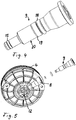
- valve body 9 is shown in detail. Evident are different sections with different diameters, which are interconnected via conical transition sections. The part of the valve body 9 projecting furthest into the valve housing 8 in the installed state has the smallest diameter.
- valve housing 8 is located on the underside of the housing cover and is directed radially to the longitudinal axis of the housing cover. As a result, a total small construction based on the axial direction of the fuel filter or housing cover is achieved.
Landscapes
- Engineering & Computer Science (AREA)
- Chemical & Material Sciences (AREA)
- Combustion & Propulsion (AREA)
- Mechanical Engineering (AREA)
- General Engineering & Computer Science (AREA)
- Chemical Kinetics & Catalysis (AREA)
- Filtration Of Liquid (AREA)
Claims (9)
- Filtre à carburant ou à huile, avec un espace collecteur de liquide (5) et avec une soupape d'évacuation (7) permettant d'évacuer du liquide de l'espace collecteur de liquide (5), la soupape d'évacuation (7) étant pourvue, dans une cage de soupape (8), d'un corps de soupape (9) réglable qui peut être déplacé entre une position de fermeture obturant l'espace collecteur de liquide (5) et une position d'ouverture dans laquelle l'espace collecteur de liquide (5) communique avec un conduit d'évacuation (12) avec un conduit d'aération (13) par l'intermédiaire duquel de l'air pénètre lors de l'évacuation du liquide et qui peut aussi être ouvert ou fermé par le corps de soupape (9), caractérisé en ce que le conduit d'évacuation (12) et le conduit d'aération (13) sont exécutés en tant que conduits séparés, le conduit d'évacuation (12) étant ouvert en premier, suivi du conduit d'aération (13), pendant le mouvement d'ouverture du corps de soupape (9), le conduit d'évacuation (12) évoluant en dehors du corps de soupape (9).
- Filtre à carburant ou à huile selon la revendication 1, caractérisé en ce que le conduit d'aération (13) pénètre dans l'espace collecteur de liquide (5) et que l'ouverture d'entrée (16) du conduit d'aération (13) dans l'espace collecteur de liquide (5) se situe à un niveau plus élevé que l'ouverture d'entrée (14) du conduit d'évacuation (12) dans l'espace collecteur de liquide (5).
- Filtre à carburant ou à huile selon la revendication 1 ou 2, caractérisé en ce que le conduit d'évacuation (12) et le conduit d'aération (13) évoluent respectivement, au moins sur certaines sections, en sens radial par rapport à l'axe longitudinal (11) du corps de soupape (9).
- Filtre à carburant ou à huile selon la revendication 3, caractérisé en ce que le conduit d'évacuation (12) et le conduit d'aération (13) sont disposés à des côtés diamétralement opposés du corps de soupape (9).
- Filtre à carburant ou à huile selon l'une des revendications 1 à 4, caractérisé en ce que l'axe longitudinal (11) du corps de soupape (9) évolue en sens radial par rapport à l'axe longitudinal d'un boîtier (2) du filtre à carburant ou à huile (1).
- Filtre à carburant ou à huile selon l'une des revendications 1 à 5, caractérisé en ce que la soupape d'évacuation (7) est montée dans un couvercle de boîtier (4) pouvant être relié au boîtier (2) du filtre à carburant ou à huile (1), sur la face inférieure du filtre à carburant ou à huile (1).
- Filtre à carburant ou à huile selon l'une des revendications 1 à 6, caractérisé en ce que le conduit d'évacuation (12) et le conduit d'aération (13) sont décalés en sens axial l'un par rapport à l'autre, considéré par rapport à l'axe longitudinal (11) du corps de soupape (9).
- Filtre à carburant ou à huile selon l'une des revendications 1 à 7, caractérisé en ce que le corps de soupape (9) peut être vissé dans la cage de soupape (8).
- Filtre à carburant ou à huile selon la revendication 8, caractérisé en ce qu'un filet extérieur (20) du corps de soupape (9) se situe entre les ouvertures d'écoulement (14, 16) du conduit d'évacuation (12) et du conduit d'aération (13) dans la cage de soupape (8).
Priority Applications (1)
| Application Number | Priority Date | Filing Date | Title |
|---|---|---|---|
| EP17165219.1A EP3211206A1 (fr) | 2013-08-15 | 2014-07-17 | Filtre pour liquide, en particulier filtre à carburant |
Applications Claiming Priority (2)
| Application Number | Priority Date | Filing Date | Title |
|---|---|---|---|
| DE102013013487.0A DE102013013487A1 (de) | 2013-08-15 | 2013-08-15 | Flüssigkeitsfilter, insbesondere Kraftstofffilter |
| PCT/EP2014/065325 WO2015022138A1 (fr) | 2013-08-15 | 2014-07-17 | Filtre à liquide, notamment filtre à carburant |
Related Child Applications (1)
| Application Number | Title | Priority Date | Filing Date |
|---|---|---|---|
| EP17165219.1A Division EP3211206A1 (fr) | 2013-08-15 | 2014-07-17 | Filtre pour liquide, en particulier filtre à carburant |
Publications (2)
| Publication Number | Publication Date |
|---|---|
| EP3033517A1 EP3033517A1 (fr) | 2016-06-22 |
| EP3033517B1 true EP3033517B1 (fr) | 2017-05-03 |
Family
ID=51257472
Family Applications (2)
| Application Number | Title | Priority Date | Filing Date |
|---|---|---|---|
| EP14744798.1A Active EP3033517B1 (fr) | 2013-08-15 | 2014-07-17 | Filtre à liquide,notamment filtre a carburant |
| EP17165219.1A Withdrawn EP3211206A1 (fr) | 2013-08-15 | 2014-07-17 | Filtre pour liquide, en particulier filtre à carburant |
Family Applications After (1)
| Application Number | Title | Priority Date | Filing Date |
|---|---|---|---|
| EP17165219.1A Withdrawn EP3211206A1 (fr) | 2013-08-15 | 2014-07-17 | Filtre pour liquide, en particulier filtre à carburant |
Country Status (3)
| Country | Link |
|---|---|
| EP (2) | EP3033517B1 (fr) |
| DE (1) | DE102013013487A1 (fr) |
| WO (1) | WO2015022138A1 (fr) |
Families Citing this family (4)
| Publication number | Priority date | Publication date | Assignee | Title |
|---|---|---|---|---|
| CN109195678B (zh) * | 2016-06-09 | 2020-12-18 | 康明斯过滤Ip公司 | 用于过滤器组件的自调节空气管理阀 |
| DE102016009844A1 (de) * | 2016-08-16 | 2018-02-22 | Mann + Hummel Gmbh | Filterelementanordnung mit Dichtelement und Filtersystem |
| US10914228B2 (en) | 2016-11-15 | 2021-02-09 | Cummins Inc. | Waste heat recovery with active coolant pressure control system |
| CN114109676B (zh) * | 2021-11-25 | 2023-03-07 | 上海弗列加滤清器有限公司 | 一种自排水模块、燃油滤清器及车辆 |
Family Cites Families (5)
| Publication number | Priority date | Publication date | Assignee | Title |
|---|---|---|---|---|
| US4515690A (en) * | 1982-08-06 | 1985-05-07 | Nissan Motor Company, Limited | Fuel supply system for diesel engines |
| US8057669B2 (en) * | 2005-02-22 | 2011-11-15 | Baldwin Filters, Inc. | Filter element and filter assembly including locking mechanism |
| US20080110812A1 (en) * | 2006-11-13 | 2008-05-15 | Mahle Tennex Industries, Inc. | Separated water treatment system for diesel fuel engine |
| FR2909732B1 (fr) * | 2006-12-12 | 2011-09-23 | Filtrauto | Dispositif de filtration de carburant a deux niveaux |
| DE102010046528A1 (de) | 2010-09-24 | 2012-03-29 | Mahle International Gmbh | Fluidfilter |
-
2013
- 2013-08-15 DE DE102013013487.0A patent/DE102013013487A1/de not_active Withdrawn
-
2014
- 2014-07-17 EP EP14744798.1A patent/EP3033517B1/fr active Active
- 2014-07-17 EP EP17165219.1A patent/EP3211206A1/fr not_active Withdrawn
- 2014-07-17 WO PCT/EP2014/065325 patent/WO2015022138A1/fr active Application Filing
Non-Patent Citations (1)
| Title |
|---|
| None * |
Also Published As
| Publication number | Publication date |
|---|---|
| EP3033517A1 (fr) | 2016-06-22 |
| DE102013013487A1 (de) | 2015-02-19 |
| EP3211206A1 (fr) | 2017-08-30 |
| WO2015022138A1 (fr) | 2015-02-19 |
Similar Documents
| Publication | Publication Date | Title |
|---|---|---|
| EP1382810B1 (fr) | Separateur d'huile pour un système de aeration d'un moteur à combustion interne | |
| EP1382809B1 (fr) | Filtre | |
| EP2046473B1 (fr) | Dispositif de filtration | |
| EP3213803B1 (fr) | Système de filtre | |
| EP3033517B1 (fr) | Filtre à liquide,notamment filtre a carburant | |
| EP1935468A1 (fr) | Filtre à carburant | |
| DE102017006874B4 (de) | Ringfilterelement, Filtereinrichtung und Kurbelgehäuse mit einer solchen Filtereinrichtung | |
| EP3145618B1 (fr) | Dispositif de filtration | |
| EP2808071B1 (fr) | Dispositif de filtre, en particulier pour un véhicule automobile | |
| EP2923045B1 (fr) | Combinaison de filtres de carter d'huile, carter d'huile et dispositif d'évacuation d'une combinaison de filtres de carter d'huile | |
| EP3352877B1 (fr) | Dispositif filtrant avec pompe | |
| DE202007003292U1 (de) | Ölabscheider mit mindestens einem Zyklon | |
| WO2018010917A1 (fr) | Dispositif de filtration de liquide | |
| EP3691769B1 (fr) | Élément filtrant comprenant une fonction d'évacuation d'air pour le raccord suspendu à une tête de filtre ainsi que système de filtration | |
| DE102010027787A1 (de) | Ölnebelabscheider mit Abscheiderumgehungsventil | |
| EP3618941A1 (fr) | Élément filtrant pour filtration de liquide | |
| DE102013008987A1 (de) | Filterelement | |
| WO2018115252A1 (fr) | Commande séquentielle de fluide au moyen d'un dispositif d'étanchéité | |
| EP3615786A1 (fr) | Dispositif de régulation pour un moteur à combustion interne | |
| DE102007035431B4 (de) | Regelventil insbesondere für Fluide mit Abströmmöglichkeit für große Massenströme | |
| DE10232044A1 (de) | Überdruckventil in einer Filtereinrichtung | |
| DE102011002916A1 (de) | Fluidablasseinrichtung | |
| EP2557348A1 (fr) | Séparateur de condensat | |
| DE102015120020A1 (de) | Ventilkolben für ein Steuerventil | |
| DE102014109044A1 (de) | Kraftstofffilter mit Entlüftungsventil |
Legal Events
| Date | Code | Title | Description |
|---|---|---|---|
| PUAI | Public reference made under article 153(3) epc to a published international application that has entered the european phase |
Free format text: ORIGINAL CODE: 0009012 |
|
| 17P | Request for examination filed |
Effective date: 20160115 |
|
| AK | Designated contracting states |
Kind code of ref document: A1 Designated state(s): AL AT BE BG CH CY CZ DE DK EE ES FI FR GB GR HR HU IE IS IT LI LT LU LV MC MK MT NL NO PL PT RO RS SE SI SK SM TR |
|
| AX | Request for extension of the european patent |
Extension state: BA ME |
|
| DAX | Request for extension of the european patent (deleted) | ||
| GRAP | Despatch of communication of intention to grant a patent |
Free format text: ORIGINAL CODE: EPIDOSNIGR1 |
|
| INTG | Intention to grant announced |
Effective date: 20170102 |
|
| GRAJ | Information related to disapproval of communication of intention to grant by the applicant or resumption of examination proceedings by the epo deleted |
Free format text: ORIGINAL CODE: EPIDOSDIGR1 |
|
| GRAP | Despatch of communication of intention to grant a patent |
Free format text: ORIGINAL CODE: EPIDOSNIGR1 |
|
| INTC | Intention to grant announced (deleted) | ||
| GRAS | Grant fee paid |
Free format text: ORIGINAL CODE: EPIDOSNIGR3 |
|
| INTG | Intention to grant announced |
Effective date: 20170303 |
|
| GRAA | (expected) grant |
Free format text: ORIGINAL CODE: 0009210 |
|
| AK | Designated contracting states |
Kind code of ref document: B1 Designated state(s): AL AT BE BG CH CY CZ DE DK EE ES FI FR GB GR HR HU IE IS IT LI LT LU LV MC MK MT NL NO PL PT RO RS SE SI SK SM TR |
|
| REG | Reference to a national code |
Ref country code: GB Ref legal event code: FG4D Free format text: NOT ENGLISH |
|
| RIN1 | Information on inventor provided before grant (corrected) |
Inventor name: GOEDECKE, MARCO Inventor name: WEIDINGER, SVEN Inventor name: FRIEDERICH, THOMAS Inventor name: BEYERLIN, HOLGER |
|
| REG | Reference to a national code |
Ref country code: AT Ref legal event code: REF Ref document number: 890288 Country of ref document: AT Kind code of ref document: T Effective date: 20170515 Ref country code: CH Ref legal event code: EP |
|
| REG | Reference to a national code |
Ref country code: IE Ref legal event code: FG4D Free format text: LANGUAGE OF EP DOCUMENT: GERMAN |
|
| REG | Reference to a national code |
Ref country code: DE Ref legal event code: R096 Ref document number: 502014003693 Country of ref document: DE |
|
| REG | Reference to a national code |
Ref country code: FR Ref legal event code: PLFP Year of fee payment: 4 |
|
| REG | Reference to a national code |
Ref country code: NL Ref legal event code: MP Effective date: 20170503 |
|
| REG | Reference to a national code |
Ref country code: LT Ref legal event code: MG4D |
|
| PG25 | Lapsed in a contracting state [announced via postgrant information from national office to epo] |
Ref country code: LT Free format text: LAPSE BECAUSE OF FAILURE TO SUBMIT A TRANSLATION OF THE DESCRIPTION OR TO PAY THE FEE WITHIN THE PRESCRIBED TIME-LIMIT Effective date: 20170503 Ref country code: NO Free format text: LAPSE BECAUSE OF FAILURE TO SUBMIT A TRANSLATION OF THE DESCRIPTION OR TO PAY THE FEE WITHIN THE PRESCRIBED TIME-LIMIT Effective date: 20170803 Ref country code: HR Free format text: LAPSE BECAUSE OF FAILURE TO SUBMIT A TRANSLATION OF THE DESCRIPTION OR TO PAY THE FEE WITHIN THE PRESCRIBED TIME-LIMIT Effective date: 20170503 Ref country code: FI Free format text: LAPSE BECAUSE OF FAILURE TO SUBMIT A TRANSLATION OF THE DESCRIPTION OR TO PAY THE FEE WITHIN THE PRESCRIBED TIME-LIMIT Effective date: 20170503 Ref country code: ES Free format text: LAPSE BECAUSE OF FAILURE TO SUBMIT A TRANSLATION OF THE DESCRIPTION OR TO PAY THE FEE WITHIN THE PRESCRIBED TIME-LIMIT Effective date: 20170503 Ref country code: GR Free format text: LAPSE BECAUSE OF FAILURE TO SUBMIT A TRANSLATION OF THE DESCRIPTION OR TO PAY THE FEE WITHIN THE PRESCRIBED TIME-LIMIT Effective date: 20170804 |
|
| PG25 | Lapsed in a contracting state [announced via postgrant information from national office to epo] |
Ref country code: NL Free format text: LAPSE BECAUSE OF FAILURE TO SUBMIT A TRANSLATION OF THE DESCRIPTION OR TO PAY THE FEE WITHIN THE PRESCRIBED TIME-LIMIT Effective date: 20170503 Ref country code: RS Free format text: LAPSE BECAUSE OF FAILURE TO SUBMIT A TRANSLATION OF THE DESCRIPTION OR TO PAY THE FEE WITHIN THE PRESCRIBED TIME-LIMIT Effective date: 20170503 Ref country code: SE Free format text: LAPSE BECAUSE OF FAILURE TO SUBMIT A TRANSLATION OF THE DESCRIPTION OR TO PAY THE FEE WITHIN THE PRESCRIBED TIME-LIMIT Effective date: 20170503 Ref country code: LV Free format text: LAPSE BECAUSE OF FAILURE TO SUBMIT A TRANSLATION OF THE DESCRIPTION OR TO PAY THE FEE WITHIN THE PRESCRIBED TIME-LIMIT Effective date: 20170503 Ref country code: IS Free format text: LAPSE BECAUSE OF FAILURE TO SUBMIT A TRANSLATION OF THE DESCRIPTION OR TO PAY THE FEE WITHIN THE PRESCRIBED TIME-LIMIT Effective date: 20170903 Ref country code: PL Free format text: LAPSE BECAUSE OF FAILURE TO SUBMIT A TRANSLATION OF THE DESCRIPTION OR TO PAY THE FEE WITHIN THE PRESCRIBED TIME-LIMIT Effective date: 20170503 Ref country code: BG Free format text: LAPSE BECAUSE OF FAILURE TO SUBMIT A TRANSLATION OF THE DESCRIPTION OR TO PAY THE FEE WITHIN THE PRESCRIBED TIME-LIMIT Effective date: 20170803 |
|
| PG25 | Lapsed in a contracting state [announced via postgrant information from national office to epo] |
Ref country code: SK Free format text: LAPSE BECAUSE OF FAILURE TO SUBMIT A TRANSLATION OF THE DESCRIPTION OR TO PAY THE FEE WITHIN THE PRESCRIBED TIME-LIMIT Effective date: 20170503 Ref country code: EE Free format text: LAPSE BECAUSE OF FAILURE TO SUBMIT A TRANSLATION OF THE DESCRIPTION OR TO PAY THE FEE WITHIN THE PRESCRIBED TIME-LIMIT Effective date: 20170503 Ref country code: DK Free format text: LAPSE BECAUSE OF FAILURE TO SUBMIT A TRANSLATION OF THE DESCRIPTION OR TO PAY THE FEE WITHIN THE PRESCRIBED TIME-LIMIT Effective date: 20170503 Ref country code: CZ Free format text: LAPSE BECAUSE OF FAILURE TO SUBMIT A TRANSLATION OF THE DESCRIPTION OR TO PAY THE FEE WITHIN THE PRESCRIBED TIME-LIMIT Effective date: 20170503 Ref country code: RO Free format text: LAPSE BECAUSE OF FAILURE TO SUBMIT A TRANSLATION OF THE DESCRIPTION OR TO PAY THE FEE WITHIN THE PRESCRIBED TIME-LIMIT Effective date: 20170503 |
|
| REG | Reference to a national code |
Ref country code: DE Ref legal event code: R097 Ref document number: 502014003693 Country of ref document: DE |
|
| PG25 | Lapsed in a contracting state [announced via postgrant information from national office to epo] |
Ref country code: SM Free format text: LAPSE BECAUSE OF FAILURE TO SUBMIT A TRANSLATION OF THE DESCRIPTION OR TO PAY THE FEE WITHIN THE PRESCRIBED TIME-LIMIT Effective date: 20170503 Ref country code: IT Free format text: LAPSE BECAUSE OF FAILURE TO SUBMIT A TRANSLATION OF THE DESCRIPTION OR TO PAY THE FEE WITHIN THE PRESCRIBED TIME-LIMIT Effective date: 20170503 |
|
| REG | Reference to a national code |
Ref country code: CH Ref legal event code: PL |
|
| PLBE | No opposition filed within time limit |
Free format text: ORIGINAL CODE: 0009261 |
|
| STAA | Information on the status of an ep patent application or granted ep patent |
Free format text: STATUS: NO OPPOSITION FILED WITHIN TIME LIMIT |
|
| 26N | No opposition filed |
Effective date: 20180206 |
|
| REG | Reference to a national code |
Ref country code: IE Ref legal event code: MM4A |
|
| PG25 | Lapsed in a contracting state [announced via postgrant information from national office to epo] |
Ref country code: CH Free format text: LAPSE BECAUSE OF NON-PAYMENT OF DUE FEES Effective date: 20170731 Ref country code: LI Free format text: LAPSE BECAUSE OF NON-PAYMENT OF DUE FEES Effective date: 20170731 Ref country code: IE Free format text: LAPSE BECAUSE OF NON-PAYMENT OF DUE FEES Effective date: 20170717 |
|
| PG25 | Lapsed in a contracting state [announced via postgrant information from national office to epo] |
Ref country code: SI Free format text: LAPSE BECAUSE OF FAILURE TO SUBMIT A TRANSLATION OF THE DESCRIPTION OR TO PAY THE FEE WITHIN THE PRESCRIBED TIME-LIMIT Effective date: 20170503 |
|
| REG | Reference to a national code |
Ref country code: BE Ref legal event code: MM Effective date: 20170731 |
|
| PG25 | Lapsed in a contracting state [announced via postgrant information from national office to epo] |
Ref country code: LU Free format text: LAPSE BECAUSE OF NON-PAYMENT OF DUE FEES Effective date: 20170717 |
|
| REG | Reference to a national code |
Ref country code: DE Ref legal event code: R081 Ref document number: 502014003693 Country of ref document: DE Owner name: MANN+HUMMEL GMBH, DE Free format text: FORMER OWNER: MANN + HUMMEL GMBH, 71638 LUDWIGSBURG, DE |
|
| REG | Reference to a national code |
Ref country code: FR Ref legal event code: PLFP Year of fee payment: 5 |
|
| PG25 | Lapsed in a contracting state [announced via postgrant information from national office to epo] |
Ref country code: BE Free format text: LAPSE BECAUSE OF NON-PAYMENT OF DUE FEES Effective date: 20170731 |
|
| PG25 | Lapsed in a contracting state [announced via postgrant information from national office to epo] |
Ref country code: MT Free format text: LAPSE BECAUSE OF FAILURE TO SUBMIT A TRANSLATION OF THE DESCRIPTION OR TO PAY THE FEE WITHIN THE PRESCRIBED TIME-LIMIT Effective date: 20170503 |
|
| GBPC | Gb: european patent ceased through non-payment of renewal fee |
Effective date: 20180717 |
|
| PG25 | Lapsed in a contracting state [announced via postgrant information from national office to epo] |
Ref country code: GB Free format text: LAPSE BECAUSE OF NON-PAYMENT OF DUE FEES Effective date: 20180717 |
|
| PG25 | Lapsed in a contracting state [announced via postgrant information from national office to epo] |
Ref country code: MC Free format text: LAPSE BECAUSE OF FAILURE TO SUBMIT A TRANSLATION OF THE DESCRIPTION OR TO PAY THE FEE WITHIN THE PRESCRIBED TIME-LIMIT Effective date: 20170503 Ref country code: HU Free format text: LAPSE BECAUSE OF FAILURE TO SUBMIT A TRANSLATION OF THE DESCRIPTION OR TO PAY THE FEE WITHIN THE PRESCRIBED TIME-LIMIT; INVALID AB INITIO Effective date: 20140717 |
|
| PG25 | Lapsed in a contracting state [announced via postgrant information from national office to epo] |
Ref country code: CY Free format text: LAPSE BECAUSE OF FAILURE TO SUBMIT A TRANSLATION OF THE DESCRIPTION OR TO PAY THE FEE WITHIN THE PRESCRIBED TIME-LIMIT Effective date: 20170503 |
|
| PG25 | Lapsed in a contracting state [announced via postgrant information from national office to epo] |
Ref country code: MK Free format text: LAPSE BECAUSE OF FAILURE TO SUBMIT A TRANSLATION OF THE DESCRIPTION OR TO PAY THE FEE WITHIN THE PRESCRIBED TIME-LIMIT Effective date: 20170503 |
|
| PG25 | Lapsed in a contracting state [announced via postgrant information from national office to epo] |
Ref country code: TR Free format text: LAPSE BECAUSE OF FAILURE TO SUBMIT A TRANSLATION OF THE DESCRIPTION OR TO PAY THE FEE WITHIN THE PRESCRIBED TIME-LIMIT Effective date: 20170503 |
|
| PG25 | Lapsed in a contracting state [announced via postgrant information from national office to epo] |
Ref country code: PT Free format text: LAPSE BECAUSE OF FAILURE TO SUBMIT A TRANSLATION OF THE DESCRIPTION OR TO PAY THE FEE WITHIN THE PRESCRIBED TIME-LIMIT Effective date: 20170503 |
|
| PG25 | Lapsed in a contracting state [announced via postgrant information from national office to epo] |
Ref country code: AL Free format text: LAPSE BECAUSE OF FAILURE TO SUBMIT A TRANSLATION OF THE DESCRIPTION OR TO PAY THE FEE WITHIN THE PRESCRIBED TIME-LIMIT Effective date: 20170503 |
|
| REG | Reference to a national code |
Ref country code: AT Ref legal event code: MM01 Ref document number: 890288 Country of ref document: AT Kind code of ref document: T Effective date: 20190717 |
|
| PG25 | Lapsed in a contracting state [announced via postgrant information from national office to epo] |
Ref country code: AT Free format text: LAPSE BECAUSE OF NON-PAYMENT OF DUE FEES Effective date: 20190717 |
|
| P01 | Opt-out of the competence of the unified patent court (upc) registered |
Effective date: 20230731 |
|
| PGFP | Annual fee paid to national office [announced via postgrant information from national office to epo] |
Ref country code: FR Payment date: 20230726 Year of fee payment: 10 Ref country code: DE Payment date: 20230719 Year of fee payment: 10 |