EP3033509B1 - Gas turbine engine comprising a protective panel and frame therefor - Google Patents
Gas turbine engine comprising a protective panel and frame therefor Download PDFInfo
- Publication number
- EP3033509B1 EP3033509B1 EP14836394.8A EP14836394A EP3033509B1 EP 3033509 B1 EP3033509 B1 EP 3033509B1 EP 14836394 A EP14836394 A EP 14836394A EP 3033509 B1 EP3033509 B1 EP 3033509B1
- Authority
- EP
- European Patent Office
- Prior art keywords
- radially outer
- frame
- panel
- gas turbine
- turbine engine
- Prior art date
- Legal status (The legal status is an assumption and is not a legal conclusion. Google has not performed a legal analysis and makes no representation as to the accuracy of the status listed.)
- Active
Links
- 230000001681 protective effect Effects 0.000 title 1
- 239000007789 gas Substances 0.000 description 28
- 239000011153 ceramic matrix composite Substances 0.000 description 10
- 239000000835 fiber Substances 0.000 description 9
- 239000000446 fuel Substances 0.000 description 6
- 239000002184 metal Substances 0.000 description 6
- 230000008901 benefit Effects 0.000 description 5
- 230000004323 axial length Effects 0.000 description 3
- 239000000853 adhesive Substances 0.000 description 2
- 230000001070 adhesive effect Effects 0.000 description 2
- 230000006835 compression Effects 0.000 description 2
- 238000007906 compression Methods 0.000 description 2
- 238000005336 cracking Methods 0.000 description 2
- 239000000463 material Substances 0.000 description 2
- 230000003068 static effect Effects 0.000 description 2
- 239000000919 ceramic Substances 0.000 description 1
- 230000008859 change Effects 0.000 description 1
- 230000007423 decrease Effects 0.000 description 1
- 239000004744 fabric Substances 0.000 description 1
- 238000004519 manufacturing process Methods 0.000 description 1
- 238000000034 method Methods 0.000 description 1
- 238000012986 modification Methods 0.000 description 1
- 230000004048 modification Effects 0.000 description 1
- 230000009467 reduction Effects 0.000 description 1
- 230000007480 spreading Effects 0.000 description 1
- 238000003892 spreading Methods 0.000 description 1
- 238000011144 upstream manufacturing Methods 0.000 description 1
Images


Classifications
-
- F—MECHANICAL ENGINEERING; LIGHTING; HEATING; WEAPONS; BLASTING
- F23—COMBUSTION APPARATUS; COMBUSTION PROCESSES
- F23R—GENERATING COMBUSTION PRODUCTS OF HIGH PRESSURE OR HIGH VELOCITY, e.g. GAS-TURBINE COMBUSTION CHAMBERS
- F23R3/00—Continuous combustion chambers using liquid or gaseous fuel
- F23R3/002—Wall structures
-
- C—CHEMISTRY; METALLURGY
- C04—CEMENTS; CONCRETE; ARTIFICIAL STONE; CERAMICS; REFRACTORIES
- C04B—LIME, MAGNESIA; SLAG; CEMENTS; COMPOSITIONS THEREOF, e.g. MORTARS, CONCRETE OR LIKE BUILDING MATERIALS; ARTIFICIAL STONE; CERAMICS; REFRACTORIES; TREATMENT OF NATURAL STONE
- C04B35/00—Shaped ceramic products characterised by their composition; Ceramics compositions; Processing powders of inorganic compounds preparatory to the manufacturing of ceramic products
- C04B35/71—Ceramic products containing macroscopic reinforcing agents
- C04B35/78—Ceramic products containing macroscopic reinforcing agents containing non-metallic materials
- C04B35/80—Fibres, filaments, whiskers, platelets, or the like
-
- F—MECHANICAL ENGINEERING; LIGHTING; HEATING; WEAPONS; BLASTING
- F01—MACHINES OR ENGINES IN GENERAL; ENGINE PLANTS IN GENERAL; STEAM ENGINES
- F01D—NON-POSITIVE DISPLACEMENT MACHINES OR ENGINES, e.g. STEAM TURBINES
- F01D11/00—Preventing or minimising internal leakage of working-fluid, e.g. between stages
- F01D11/08—Preventing or minimising internal leakage of working-fluid, e.g. between stages for sealing space between rotor blade tips and stator
-
- F—MECHANICAL ENGINEERING; LIGHTING; HEATING; WEAPONS; BLASTING
- F02—COMBUSTION ENGINES; HOT-GAS OR COMBUSTION-PRODUCT ENGINE PLANTS
- F02C—GAS-TURBINE PLANTS; AIR INTAKES FOR JET-PROPULSION PLANTS; CONTROLLING FUEL SUPPLY IN AIR-BREATHING JET-PROPULSION PLANTS
- F02C7/00—Features, components parts, details or accessories, not provided for in, or of interest apart form groups F02C1/00 - F02C6/00; Air intakes for jet-propulsion plants
- F02C7/24—Heat or noise insulation
-
- F—MECHANICAL ENGINEERING; LIGHTING; HEATING; WEAPONS; BLASTING
- F02—COMBUSTION ENGINES; HOT-GAS OR COMBUSTION-PRODUCT ENGINE PLANTS
- F02K—JET-PROPULSION PLANTS
- F02K1/00—Plants characterised by the form or arrangement of the jet pipe or nozzle; Jet pipes or nozzles peculiar thereto
- F02K1/78—Other construction of jet pipes
- F02K1/82—Jet pipe walls, e.g. liners
- F02K1/822—Heat insulating structures or liners, cooling arrangements, e.g. post combustion liners; Infra-red radiation suppressors
-
- F—MECHANICAL ENGINEERING; LIGHTING; HEATING; WEAPONS; BLASTING
- F23—COMBUSTION APPARATUS; COMBUSTION PROCESSES
- F23M—CASINGS, LININGS, WALLS OR DOORS SPECIALLY ADAPTED FOR COMBUSTION CHAMBERS, e.g. FIREBRIDGES; DEVICES FOR DEFLECTING AIR, FLAMES OR COMBUSTION PRODUCTS IN COMBUSTION CHAMBERS; SAFETY ARRANGEMENTS SPECIALLY ADAPTED FOR COMBUSTION APPARATUS; DETAILS OF COMBUSTION CHAMBERS, NOT OTHERWISE PROVIDED FOR
- F23M5/00—Casings; Linings; Walls
- F23M5/04—Supports for linings
-
- F—MECHANICAL ENGINEERING; LIGHTING; HEATING; WEAPONS; BLASTING
- F23—COMBUSTION APPARATUS; COMBUSTION PROCESSES
- F23R—GENERATING COMBUSTION PRODUCTS OF HIGH PRESSURE OR HIGH VELOCITY, e.g. GAS-TURBINE COMBUSTION CHAMBERS
- F23R3/00—Continuous combustion chambers using liquid or gaseous fuel
- F23R3/007—Continuous combustion chambers using liquid or gaseous fuel constructed mainly of ceramic components
-
- F—MECHANICAL ENGINEERING; LIGHTING; HEATING; WEAPONS; BLASTING
- F23—COMBUSTION APPARATUS; COMBUSTION PROCESSES
- F23R—GENERATING COMBUSTION PRODUCTS OF HIGH PRESSURE OR HIGH VELOCITY, e.g. GAS-TURBINE COMBUSTION CHAMBERS
- F23R3/00—Continuous combustion chambers using liquid or gaseous fuel
- F23R3/42—Continuous combustion chambers using liquid or gaseous fuel characterised by the arrangement or form of the flame tubes or combustion chambers
- F23R3/60—Support structures; Attaching or mounting means
-
- C—CHEMISTRY; METALLURGY
- C04—CEMENTS; CONCRETE; ARTIFICIAL STONE; CERAMICS; REFRACTORIES
- C04B—LIME, MAGNESIA; SLAG; CEMENTS; COMPOSITIONS THEREOF, e.g. MORTARS, CONCRETE OR LIKE BUILDING MATERIALS; ARTIFICIAL STONE; CERAMICS; REFRACTORIES; TREATMENT OF NATURAL STONE
- C04B2235/00—Aspects relating to ceramic starting mixtures or sintered ceramic products
- C04B2235/02—Composition of constituents of the starting material or of secondary phases of the final product
- C04B2235/50—Constituents or additives of the starting mixture chosen for their shape or used because of their shape or their physical appearance
- C04B2235/52—Constituents or additives characterised by their shapes
- C04B2235/5208—Fibers
- C04B2235/5268—Orientation of the fibers
-
- C—CHEMISTRY; METALLURGY
- C04—CEMENTS; CONCRETE; ARTIFICIAL STONE; CERAMICS; REFRACTORIES
- C04B—LIME, MAGNESIA; SLAG; CEMENTS; COMPOSITIONS THEREOF, e.g. MORTARS, CONCRETE OR LIKE BUILDING MATERIALS; ARTIFICIAL STONE; CERAMICS; REFRACTORIES; TREATMENT OF NATURAL STONE
- C04B2235/00—Aspects relating to ceramic starting mixtures or sintered ceramic products
- C04B2235/70—Aspects relating to sintered or melt-casted ceramic products
- C04B2235/94—Products characterised by their shape
-
- F—MECHANICAL ENGINEERING; LIGHTING; HEATING; WEAPONS; BLASTING
- F02—COMBUSTION ENGINES; HOT-GAS OR COMBUSTION-PRODUCT ENGINE PLANTS
- F02K—JET-PROPULSION PLANTS
- F02K1/00—Plants characterised by the form or arrangement of the jet pipe or nozzle; Jet pipes or nozzles peculiar thereto
- F02K1/78—Other construction of jet pipes
- F02K1/82—Jet pipe walls, e.g. liners
-
- F—MECHANICAL ENGINEERING; LIGHTING; HEATING; WEAPONS; BLASTING
- F05—INDEXING SCHEMES RELATING TO ENGINES OR PUMPS IN VARIOUS SUBCLASSES OF CLASSES F01-F04
- F05D—INDEXING SCHEME FOR ASPECTS RELATING TO NON-POSITIVE-DISPLACEMENT MACHINES OR ENGINES, GAS-TURBINES OR JET-PROPULSION PLANTS
- F05D2220/00—Application
- F05D2220/30—Application in turbines
- F05D2220/32—Application in turbines in gas turbines
-
- F—MECHANICAL ENGINEERING; LIGHTING; HEATING; WEAPONS; BLASTING
- F05—INDEXING SCHEMES RELATING TO ENGINES OR PUMPS IN VARIOUS SUBCLASSES OF CLASSES F01-F04
- F05D—INDEXING SCHEME FOR ASPECTS RELATING TO NON-POSITIVE-DISPLACEMENT MACHINES OR ENGINES, GAS-TURBINES OR JET-PROPULSION PLANTS
- F05D2230/00—Manufacture
- F05D2230/60—Assembly methods
-
- F—MECHANICAL ENGINEERING; LIGHTING; HEATING; WEAPONS; BLASTING
- F05—INDEXING SCHEMES RELATING TO ENGINES OR PUMPS IN VARIOUS SUBCLASSES OF CLASSES F01-F04
- F05D—INDEXING SCHEME FOR ASPECTS RELATING TO NON-POSITIVE-DISPLACEMENT MACHINES OR ENGINES, GAS-TURBINES OR JET-PROPULSION PLANTS
- F05D2240/00—Components
- F05D2240/10—Stators
- F05D2240/11—Shroud seal segments
-
- F—MECHANICAL ENGINEERING; LIGHTING; HEATING; WEAPONS; BLASTING
- F05—INDEXING SCHEMES RELATING TO ENGINES OR PUMPS IN VARIOUS SUBCLASSES OF CLASSES F01-F04
- F05D—INDEXING SCHEME FOR ASPECTS RELATING TO NON-POSITIVE-DISPLACEMENT MACHINES OR ENGINES, GAS-TURBINES OR JET-PROPULSION PLANTS
- F05D2240/00—Components
- F05D2240/35—Combustors or associated equipment
-
- F—MECHANICAL ENGINEERING; LIGHTING; HEATING; WEAPONS; BLASTING
- F05—INDEXING SCHEMES RELATING TO ENGINES OR PUMPS IN VARIOUS SUBCLASSES OF CLASSES F01-F04
- F05D—INDEXING SCHEME FOR ASPECTS RELATING TO NON-POSITIVE-DISPLACEMENT MACHINES OR ENGINES, GAS-TURBINES OR JET-PROPULSION PLANTS
- F05D2300/00—Materials; Properties thereof
- F05D2300/60—Properties or characteristics given to material by treatment or manufacturing
- F05D2300/603—Composites; e.g. fibre-reinforced
- F05D2300/6033—Ceramic matrix composites [CMC]
-
- F—MECHANICAL ENGINEERING; LIGHTING; HEATING; WEAPONS; BLASTING
- F23—COMBUSTION APPARATUS; COMBUSTION PROCESSES
- F23R—GENERATING COMBUSTION PRODUCTS OF HIGH PRESSURE OR HIGH VELOCITY, e.g. GAS-TURBINE COMBUSTION CHAMBERS
- F23R2900/00—Special features of, or arrangements for continuous combustion chambers; Combustion processes therefor
- F23R2900/00017—Assembling combustion chamber liners or subparts
-
- Y—GENERAL TAGGING OF NEW TECHNOLOGICAL DEVELOPMENTS; GENERAL TAGGING OF CROSS-SECTIONAL TECHNOLOGIES SPANNING OVER SEVERAL SECTIONS OF THE IPC; TECHNICAL SUBJECTS COVERED BY FORMER USPC CROSS-REFERENCE ART COLLECTIONS [XRACs] AND DIGESTS
- Y02—TECHNOLOGIES OR APPLICATIONS FOR MITIGATION OR ADAPTATION AGAINST CLIMATE CHANGE
- Y02T—CLIMATE CHANGE MITIGATION TECHNOLOGIES RELATED TO TRANSPORTATION
- Y02T50/00—Aeronautics or air transport
- Y02T50/60—Efficient propulsion technologies, e.g. for aircraft
Definitions
- Gas turbine engines include a core flow path where air is communicated to a combustor section, combined with fuel, and ignited to generate a high pressure exhaust gas stream.
- Various portions of the engine are directly exposed to this high pressure exhaust gas stream.
- Some example portions include combustor liners and exit nozzles.
- the high pressure exhaust gas stream includes relatively hot gases.
- the portions of the engine that are exposed to these hot gases include metal plates (e.g., walls, brackets, supports) configured to absorb various structural load in the engine.
- metal plates e.g., walls, brackets, supports
- CMC ceramic matrix composite
- EP 2 107 307 A1 discloses a prior art gas turbine combustor with sectorised internal and external walls.
- the panel is spaced-apart from the plate by the frame.
- first and second grips are semicircular and engage both a radially outer surface and a radially inner surface of a respective one of the first radially outer flange and the second radially outer flange.
- the frame includes an outer frame and an inner frame providing the first and second grips, the outer frame engaging a radially inner surface of the first radially outer flange and a radially inner surface of the second radially outer flange, the inner frame engaging a radially outer surface of the first radially outer flange and a radially outer surface of the second radially outer flange.
- the plurality of shims each include bends at ends thereof to prevent movement of the shims relative to the panel.
- the plurality of shims each include grooves receiving projections of an associated one of the first grip and the second grip.
- the plate is a portion of one of a combustor liner and an exhaust nozzle.
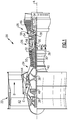
- FIG. 1 schematically illustrates an example gas turbine engine 20 that includes a fan section 22, a compressor section 24, a combustor section 26 and a turbine section 28.
- Alternative engines might include an augmenter section (not shown) among other systems or features.
- the fan section 22 drives air along a bypass flow path B while the compressor section 24 draws air in along a core flow path C where air is compressed and communicated to a combustor section 26.
- air is mixed with fuel and ignited to generate a high pressure exhaust gas stream that expands through the turbine section 28 where energy is extracted and utilized to drive the fan section 22 and the compressor section 24.
- turbofan gas turbine engine depicts a turbofan gas turbine engine
- the concepts described herein are not limited to use with turbofans as the teachings may be applied to other types of turbine engines; for example a turbine engine including a three-spool architecture in which three spools concentrically rotate about a common axis and where a low spool enables a low pressure turbine to drive a fan via a gearbox, an intermediate spool that enables an intermediate pressure turbine to drive a first compressor of the compressor section, and a high spool that enables a high pressure turbine to drive a high pressure compressor of the compressor section.
- the concepts disclosed herein can further be applied outside of gas turbine engines.
- the example engine 20 generally includes a low speed spool 30 and a high speed spool 32 mounted for rotation about an engine central longitudinal axis A relative to an engine static structure 36 via several bearing systems 38. It should be understood that various bearing systems 38 at various locations may alternatively or additionally be provided.
- the low speed spool 30 generally includes an inner shaft 40 that connects a fan 42 and a low pressure (or first) compressor section 44 to a low pressure (or first) turbine section 46.
- the inner shaft 40 drives the fan 42 through a speed change device, such as a geared architecture 48, to drive the fan 42 at a lower speed than the low speed spool 30.
- the high-speed spool 32 includes an outer shaft 50 that interconnects a high pressure (or second) compressor section 52 and a high pressure (or second) turbine section 54.
- the inner shaft 40 and the outer shaft 50 are concentric and rotate via the bearing systems 38 about the engine central longitudinal axis A.
- a combustor 56 is arranged between the high pressure compressor 52 and the high pressure turbine 54.
- the high pressure turbine 54 includes at least two stages to provide a double stage high pressure turbine 54.
- the high pressure turbine 54 includes only a single stage.
- a "high pressure" compressor or turbine experiences a higher pressure than a corresponding "low pressure” compressor or turbine.
- the example low pressure turbine 46 has a pressure ratio that is greater than about five (5).
- the pressure ratio of the example low pressure turbine 46 is measured prior to an inlet of the low pressure turbine 46 as related to the pressure measured at the outlet of the low pressure turbine 46 prior to an exhaust nozzle.
- a mid-turbine frame 57 of the engine static structure 36 is arranged generally between the high pressure turbine 54 and the low pressure turbine 46.
- the mid-turbine frame 57 further supports bearing systems 38 in the turbine section 28 as well as setting airflow entering the low pressure turbine 46.
- the core airflow C is compressed by the low pressure compressor 44 then by the high pressure compressor 52 mixed with fuel and ignited in the combustor 56 to produce high speed exhaust gases that are then expanded through the high pressure turbine 54 and low pressure turbine 46.
- the mid-turbine frame 57 includes vanes 60, which are in the core airflow path and function as an inlet guide vane for the low pressure turbine 46. Utilizing the vane 60 of the mid-turbine frame 57 as the inlet guide vane for low pressure turbine 46 decreases the length of the low pressure turbine 46 without increasing the axial length of the mid-turbine frame 57. Reducing or eliminating the number of vanes in the low pressure turbine 46 shortens the axial length of the turbine section 28. Thus, the compactness of the gas turbine engine 20 is increased and a higher power density may be achieved.
- the disclosed gas turbine engine 20 in one example is a high-bypass geared aircraft engine.
- the gas turbine engine 20 includes a bypass ratio greater than about six (6), with an example embodiment being greater than about ten (10).
- the example geared architecture 48 is an epicyclical gear train, such as a planetary gear system, star gear system or other known gear system, with a gear reduction ratio of greater than about 2.3.
- the gas turbine engine 20 includes a bypass ratio greater than about ten (10:1) and the fan diameter is significantly larger than an outer diameter of the low pressure compressor 44. It should be understood, however, that the above parameters are only exemplary of one embodiment of a gas turbine engine including a geared architecture and that the present disclosure is applicable to other gas turbine engines.
- the fan section 22 of the engine 20 is designed for a particular flight condition typically cruise at about 0.8 Mach and about 35,000 feet (10,668m).
- the flight condition of 0.8 Mach and 35,000 ft. (10,668m), with the engine at its best fuel consumption also known as "bucket cruise Thrust Specific Fuel Consumption ('TSFC')" is the industry standard parameter of pound-mass (lbm) of fuel per hour being burned divided by pound-force (lbf) of thrust the engine produces at that minimum point.
- Low fan pressure ratio is the pressure ratio across the fan blade alone, without a Fan Exit Guide Vane (“FEGV”) system.
- the low fan pressure ratio as disclosed herein according to one non-limiting embodiment is less than about 1.50. In another non-limiting embodiment the low fan pressure ratio is less than about 1.45.
- the "Low corrected fan tip speed,” as disclosed herein according to one non-limiting embodiment, is less than about 1150 ft/second (350.5 m/s).
- FIG. 2 illustrates an arrangement including a panel 62 for protecting a plate 64 according to this disclosure.
- the panel 62 is made of a ceramic matrix composite (CMC) material
- the plate 64 is made of a metal.
- CMC has the benefit of being relatively temperature resistant, while metal has the benefit of providing increased structural support. It should be understood that this application extends to other materials with similar temperature resistant and structural properties.
- the panel 62 could be formed from a single, monolithic ceramic block.
- the plate 64 in one example is a combustor liner. In another example, the plate 64 is an exhaust nozzle. It should be understood that this disclosure extends to various other types of plates arranged within the gas turbine engine 20 that may be exposed to a hot gas path, F HOT .
- the plate 64 may be flat as shown, for some applications such as an exhaust nozzle side wall, or it may be curved or have a hoop shape, in other applications such as a combustor liner.
- the panel 62 may be flat as shown, or have a bend or curvature to it, such that the surface exposed to the hot gas path F HOT has either a flat or curved shape.
- the panel 62 includes radially inner and radially outer flanges 66, 68 at a leading edge of the panel, spaced apart in a radial direction R (substantially normal to the engine central longitudinal axis A) by a slot 70 provided therebetween.
- the panel further includes radially inner and radially outer flanges 72, 74 at a trailing edge, and a slot 76 therebetween.
- the radially inner flanges 66, 72 protrude a distance D 1 axially beyond a respective one of the radially outer flanges 68, 74.
- this extension provides protection to the plate 64 and the associated frame 78, and further allows the radially inner flanges 66, 72 to be positioned in close proximity to the radially inner flanges of a similar panel (e.g., as generally represented in Figure 3 ).
- the panel 62 is attached to the plate 64 by way of a frame 78.
- the frame 78 is a single, unitary structure and is made of metal.
- the frame 78 securely and resiliently supports the panel 62 relative to the plate 64 and dampens vibrations of the panel 62. Further, because the panel 62 and the plate 64 are not directly connected, the frame 78 provides an effective support even considering the different rates of thermal expansion between the panel 62 and plate 64.
- the frame 78 includes a pair of grips 80, 82 configured to engage the radially outer flanges 68, 74 of the panel 62, and to support the panel 62 by holding the radially outer flanges 68, 74 in compression.
- the grips 80, 82 in this example are connected to one another by a main body portion 79, which is fastened to the plate 64 by way of a fastener 81.
- Each of the grips 80, 82 contacts each radially outer flange 68, 74 at two radially opposed points, as will be discussed in detail below.
- a plurality of shims 84, 86, 88, and 90 are provided between the radially outer flanges 68, 74 and the grips 80, 82.
- the shims 84, 86, 88, 90 have the benefit of spreading a load from the grips 80, 82 to the radially outer flanges 68, 74 to avoid damage to the panel 62.
- the grips 80, 82 are semicircular in this example. It should be understood that other shapes could be used, however. With reference to the grip 80 (and, it should be understood that the grip 82 includes similar features), the grip 80 includes a first projection 92 configured to engage an radially outer shim 84, and a semicircular portion 94 that leads to a second projection 96 configured to engage a radially inner shim 86.
- the semicircular portion 94 is formed with a radius D 2 .
- the radius D 2 dictates the load provided by the grips 80, 82 relative to the radially outer flanges 68, 74.
- An appropriate radius D 2 can be selected to provide a desired load, depending on the particular application.
- the arrangement of Figure 2 provides a panel 62 that protects the plate 64 from a relatively hot gas path F HOT .
- the hot gas path F HOT is the core flow path C.
- the hot gas path F HOT may be provided by other flow paths.
- the panels 62 can be arranged axially in series, as illustrated in Figure 3 , wherein the panel 62A is arranged axially upstream of panel 62B.
- the panels 62 can further be arranged circumferentially around the engine central longitudinal axis A to provide a sufficient level of thermal protection for the plate 64.
- panels can be arranged circumferentially adjacent one another (similar to what is illustrated in Figure 3 ) about the engine central longitudinal axis A
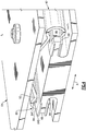
- Figure 4 is a perspective view illustrating the engagement between the grips 80, 82 and the shims 84, 86, 88, 90.
- the shim 84 is provided with a bend 84B at its ends to maintain the shim 84 in circumferential position relative to the radially outer flange 68.
- the shim 84 further includes a groove 84G along the length thereof to receive the first projection 92 of the grip 80.
- the shims 86, 88, 90 also include bends and grooves similar to the bend 84B and groove 84G.
- the shim 86 includes a groove therein receiving the second projection 96 of the grip 80. The bends and grooves ensure proper alignment between the shims 84, 86, 88, 90 and the panel 62, and an adequate engagement between the shims 84, 86, 88, 90 and the grips 80, 82.
- the frame 78 is first attached to the plate 64 by way of the fastener 81. Then, the shims 84, 86, 88, 90 are provided adjacent the flanges 68, 74, and the assembly is slid (e.g., in or out the page in Figure 2 ) into an interference fit with the grips 80, 82.
- the bends in the shims 84, 86, 88, 90 facilitate assembly by engaging and radially separating the grips 80, 82 when the initially slid into contact the grips 80, 82.
- the frame 78 could be slid into an interference fit with the shims 84, 86, 88, 90 and the flanges 68, 74, and then mounted to the plate 64.
- the shims 84, 86, 88, 90 are secured to the flanges 68, 74 by way of a fastener or an adhesive.
- the compression force provided by the grips 80, 82 creates an interference fit without the need for additional fasteners or adhesive.
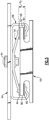
- Figure 5 illustrates an alternate arrangement for supporting the panel 62 including a two piece frame.
- the two piece frame includes an outer frame 98 and an inner frame 100.
- Each of the outer frame 98 and the inner frame 100 are attached to the panel 64 via a fastener 81.
- the outer frame 98 extends from the plate 64 axially beyond the radially outer flanges 68, 74 and engages the radially inner shims 86, 90.
- the inner frame 100 extends from the fastener 81 to the radially outer shims 84, 88.
- the outer and inner frames 98, 100 include projections (like the projections 92, 96) received in grooves in the shims 84, 86, 88, 90.
- the two piece frame provides a resilient support for the panel 62 by the outer frame 98 urging the panel 62 in a radially inward direction, and the inner frame 100 urging the panel 62 in a radially outward direction.
- the load applied to the shims 84, 86, 88, 90 is adjustable by varying the distance D 3 between the outer and inner frames 98, 100.
- an appropriate load can be selected by adjusting the size and relative positioning of the outer and inner frames 98, 100.
- the unitary frame of Figures 2-4 may have the benefit of being more easily assembled than the two piece frame of Figure 5 (e.g., because only a single frame 78 needs to be attached to the plate 64), however the example of Figure 5 may have the added benefit of easily being able to adjust the load on the panel (e.g., by varying the distance D 3 ).
- FIG. 6A-6C illustrate example CMC panels 62.
- various CMC sheets 102 are stacked on one another and formed together. Once formed, the slots 70, 76 and flanges 66, 68, 72, 74 are machined. Alternatively, the sheets may be cut to the right size, and then laid up against a mold in order to form the slots and flanges. While cost effective, this arrangement may experience cracking and/or delaminating of the CMC sheets 102 in the slots 70, 76 due to potentially high stress concentrations.
- a number of CMC sheets 104 are provided such that the axial length of the fibers F A follows the semi-circular contour 70C, 76C of the slots 70, 76.
- the axial fibers F A further interlock and cross over a plurality of circumferential fibers F C for increased strength. These circumferential fibers F C run in-and-out of the page relative to Figure 6B . Because the axial fibers F A generally follow the contour of the slots 70, 76, the stresses in the slots 70, 76 are reduced, and the chances of cracking or delaminating are minimized.
- Figure 6C illustrates another example where the axial fibers F A generally follow the contour of the slots 70, 76. Again, this provides reduced stress concentrations in the slots 70, 76.
- the example of Figure 6C includes more interweaving (relative to Figure 6B ) between circumferential fibers F C and axial fibers F A , and thus may be more expensive to manufacture. However, the increased interweaving provides an extremely effective and secure CMC panel.
- an appropriate arrangement for the panel 62 including but not limited to those illustrated in Figures 6A-6C , can be selected.
Description
- Gas turbine engines include a core flow path where air is communicated to a combustor section, combined with fuel, and ignited to generate a high pressure exhaust gas stream. Various portions of the engine are directly exposed to this high pressure exhaust gas stream. Some example portions include combustor liners and exit nozzles.
- The high pressure exhaust gas stream includes relatively hot gases. The portions of the engine that are exposed to these hot gases include metal plates (e.g., walls, brackets, supports) configured to absorb various structural load in the engine. In one known example, to protect the metal plates from a hot gas path, ceramic matrix composite (CMC) panels are directly mounted to the metal plates with threaded fasteners.
-
US 3,956,886 discloses a prior art gas turbine engine according to the preamble of claim 1. -
EP 2 107 307 A1 discloses a prior art gas turbine combustor with sectorised internal and external walls. - According to an aspect of the present invention, there is provided a gas turbine engine as set forth in claim 1.
- In an embodiment, the panel is spaced-apart from the plate by the frame.
- In a further embodiment of any of the above, the first and second grips are semicircular and engage both a radially outer surface and a radially inner surface of a respective one of the first radially outer flange and the second radially outer flange.
- In a further embodiment of any of the above, the frame includes an outer frame and an inner frame providing the first and second grips, the outer frame engaging a radially inner surface of the first radially outer flange and a radially inner surface of the second radially outer flange, the inner frame engaging a radially outer surface of the first radially outer flange and a radially outer surface of the second radially outer flange.
- In a further embodiment of any of the above, the plurality of shims each include bends at ends thereof to prevent movement of the shims relative to the panel.
- In a further embodiment of any of the above, the plurality of shims each include grooves receiving projections of an associated one of the first grip and the second grip.
- In a further embodiment of any of the above, the plate is a portion of one of a combustor liner and an exhaust nozzle.
- The embodiments, examples and alternatives of the preceding paragraphs, the claims, or the following description and drawings, including any of their various aspects or respective individual features, may be taken independently or in any combination. Features described in connection with one embodiment are applicable to all embodiments, unless such features are incompatible.
- The drawings can be briefly described as follows:
-
Figure 1 illustrates a schematic, cross-sectional view of a gas turbine engine. -
Figure 2 is a side view of a panel and frame according to this disclosure. -
Figure 3 illustrates two panels (and associated frames) arranged axially relative to one another. -
Figure 4 is a perspective view of the panel and frame according to this disclosure, and in particular illustrates the detail of the shims. -
Figure 5 illustrates an alternate frame according to this disclosure. -
Figures 6A-6C illustrate example panels having stacked fabric, crossover, and multi-fiber interlock arrangements, respectively. -
Figure 1 schematically illustrates an examplegas turbine engine 20 that includes afan section 22, acompressor section 24, a combustor section 26 and aturbine section 28. Alternative engines might include an augmenter section (not shown) among other systems or features. Thefan section 22 drives air along a bypass flow path B while thecompressor section 24 draws air in along a core flow path C where air is compressed and communicated to a combustor section 26. In the combustor section 26, air is mixed with fuel and ignited to generate a high pressure exhaust gas stream that expands through theturbine section 28 where energy is extracted and utilized to drive thefan section 22 and thecompressor section 24. - Although the disclosed non-limiting embodiment depicts a turbofan gas turbine engine, it should be understood that the concepts described herein are not limited to use with turbofans as the teachings may be applied to other types of turbine engines; for example a turbine engine including a three-spool architecture in which three spools concentrically rotate about a common axis and where a low spool enables a low pressure turbine to drive a fan via a gearbox, an intermediate spool that enables an intermediate pressure turbine to drive a first compressor of the compressor section, and a high spool that enables a high pressure turbine to drive a high pressure compressor of the compressor section. The concepts disclosed herein can further be applied outside of gas turbine engines.
- The
example engine 20 generally includes alow speed spool 30 and ahigh speed spool 32 mounted for rotation about an engine central longitudinal axis A relative to an enginestatic structure 36 viaseveral bearing systems 38. It should be understood thatvarious bearing systems 38 at various locations may alternatively or additionally be provided. - The
low speed spool 30 generally includes aninner shaft 40 that connects afan 42 and a low pressure (or first)compressor section 44 to a low pressure (or first)turbine section 46. Theinner shaft 40 drives thefan 42 through a speed change device, such as a gearedarchitecture 48, to drive thefan 42 at a lower speed than thelow speed spool 30. The high-speed spool 32 includes anouter shaft 50 that interconnects a high pressure (or second)compressor section 52 and a high pressure (or second)turbine section 54. Theinner shaft 40 and theouter shaft 50 are concentric and rotate via thebearing systems 38 about the engine central longitudinal axis A. - A
combustor 56 is arranged between thehigh pressure compressor 52 and thehigh pressure turbine 54. In one example, thehigh pressure turbine 54 includes at least two stages to provide a double stagehigh pressure turbine 54. In another example, thehigh pressure turbine 54 includes only a single stage. As used herein, a "high pressure" compressor or turbine experiences a higher pressure than a corresponding "low pressure" compressor or turbine. - The example
low pressure turbine 46 has a pressure ratio that is greater than about five (5). The pressure ratio of the examplelow pressure turbine 46 is measured prior to an inlet of thelow pressure turbine 46 as related to the pressure measured at the outlet of thelow pressure turbine 46 prior to an exhaust nozzle. - A mid-turbine frame 57 of the engine
static structure 36 is arranged generally between thehigh pressure turbine 54 and thelow pressure turbine 46. The mid-turbine frame 57 further supports bearingsystems 38 in theturbine section 28 as well as setting airflow entering thelow pressure turbine 46. - The core airflow C is compressed by the
low pressure compressor 44 then by thehigh pressure compressor 52 mixed with fuel and ignited in thecombustor 56 to produce high speed exhaust gases that are then expanded through thehigh pressure turbine 54 andlow pressure turbine 46. The mid-turbine frame 57 includesvanes 60, which are in the core airflow path and function as an inlet guide vane for thelow pressure turbine 46. Utilizing thevane 60 of the mid-turbine frame 57 as the inlet guide vane forlow pressure turbine 46 decreases the length of thelow pressure turbine 46 without increasing the axial length of the mid-turbine frame 57. Reducing or eliminating the number of vanes in thelow pressure turbine 46 shortens the axial length of theturbine section 28. Thus, the compactness of thegas turbine engine 20 is increased and a higher power density may be achieved. - The disclosed
gas turbine engine 20 in one example is a high-bypass geared aircraft engine. In a further example, thegas turbine engine 20 includes a bypass ratio greater than about six (6), with an example embodiment being greater than about ten (10). The example gearedarchitecture 48 is an epicyclical gear train, such as a planetary gear system, star gear system or other known gear system, with a gear reduction ratio of greater than about 2.3. - In one disclosed embodiment, the
gas turbine engine 20 includes a bypass ratio greater than about ten (10:1) and the fan diameter is significantly larger than an outer diameter of thelow pressure compressor 44. It should be understood, however, that the above parameters are only exemplary of one embodiment of a gas turbine engine including a geared architecture and that the present disclosure is applicable to other gas turbine engines. - A significant amount of thrust is provided by the bypass flow B due to the high bypass ratio. The
fan section 22 of theengine 20 is designed for a particular flight condition typically cruise at about 0.8 Mach and about 35,000 feet (10,668m). The flight condition of 0.8 Mach and 35,000 ft. (10,668m), with the engine at its best fuel consumption also known as "bucket cruise Thrust Specific Fuel Consumption ('TSFC')" is the industry standard parameter of pound-mass (lbm) of fuel per hour being burned divided by pound-force (lbf) of thrust the engine produces at that minimum point. - "Low fan pressure ratio" is the pressure ratio across the fan blade alone, without a Fan Exit Guide Vane ("FEGV") system. The low fan pressure ratio as disclosed herein according to one non-limiting embodiment is less than about 1.50. In another non-limiting embodiment the low fan pressure ratio is less than about 1.45.
- "Low corrected fan tip speed" is the actual fan tip speed in ft/sec divided by an industry standard temperature correction of [(Tram °R) / (518.7 °R)]0.5 (where °R = K x 9/5). The "Low corrected fan tip speed," as disclosed herein according to one non-limiting embodiment, is less than about 1150 ft/second (350.5 m/s).
-
Figure 2 illustrates an arrangement including apanel 62 for protecting aplate 64 according to this disclosure. In this example, thepanel 62 is made of a ceramic matrix composite (CMC) material, and theplate 64 is made of a metal. CMC has the benefit of being relatively temperature resistant, while metal has the benefit of providing increased structural support. It should be understood that this application extends to other materials with similar temperature resistant and structural properties. For instance, thepanel 62 could be formed from a single, monolithic ceramic block. - The
plate 64 in one example is a combustor liner. In another example, theplate 64 is an exhaust nozzle. It should be understood that this disclosure extends to various other types of plates arranged within thegas turbine engine 20 that may be exposed to a hot gas path, FHOT. Theplate 64 may be flat as shown, for some applications such as an exhaust nozzle side wall, or it may be curved or have a hoop shape, in other applications such as a combustor liner. Likewise, thepanel 62 may be flat as shown, or have a bend or curvature to it, such that the surface exposed to the hot gas path FHOT has either a flat or curved shape. - In this example, the
panel 62 includes radially inner and radiallyouter flanges slot 70 provided therebetween. The panel further includes radially inner and radiallyouter flanges slot 76 therebetween. - As illustrated herein, the radially
inner flanges outer flanges plate 64 and the associatedframe 78, and further allows the radiallyinner flanges Figure 3 ). - The
panel 62 is attached to theplate 64 by way of aframe 78. In this example, theframe 78 is a single, unitary structure and is made of metal. Theframe 78 securely and resiliently supports thepanel 62 relative to theplate 64 and dampens vibrations of thepanel 62. Further, because thepanel 62 and theplate 64 are not directly connected, theframe 78 provides an effective support even considering the different rates of thermal expansion between thepanel 62 andplate 64. - The
frame 78 includes a pair ofgrips outer flanges panel 62, and to support thepanel 62 by holding the radiallyouter flanges grips main body portion 79, which is fastened to theplate 64 by way of afastener 81. Each of thegrips outer flange - A plurality of
shims outer flanges grips shims grips outer flanges panel 62. - The
grips grip 82 includes similar features), thegrip 80 includes afirst projection 92 configured to engage an radiallyouter shim 84, and asemicircular portion 94 that leads to asecond projection 96 configured to engage a radiallyinner shim 86. Thesemicircular portion 94 is formed with a radius D2. The radius D2 dictates the load provided by thegrips outer flanges - The arrangement of
Figure 2 provides apanel 62 that protects theplate 64 from a relatively hot gas path FHOT. In one example, the hot gas path FHOT is the core flow path C. Depending on where thepanel 62 is provided in theengine 20, the hot gas path FHOT may be provided by other flow paths. - The
panels 62 can be arranged axially in series, as illustrated inFigure 3 , wherein thepanel 62A is arranged axially upstream ofpanel 62B. Thepanels 62 can further be arranged circumferentially around the engine central longitudinal axis A to provide a sufficient level of thermal protection for theplate 64. Alternatively, or in combination, panels can be arranged circumferentially adjacent one another (similar to what is illustrated inFigure 3 ) about the engine central longitudinal axis A -
Figure 4 is a perspective view illustrating the engagement between thegrips shims outer shim 84, theshim 84 is provided with abend 84B at its ends to maintain theshim 84 in circumferential position relative to the radiallyouter flange 68. Theshim 84 further includes agroove 84G along the length thereof to receive thefirst projection 92 of thegrip 80. Theshims bend 84B and groove 84G. For example, theshim 86 includes a groove therein receiving thesecond projection 96 of thegrip 80. The bends and grooves ensure proper alignment between theshims panel 62, and an adequate engagement between theshims grips - In one example assembly method, the
frame 78 is first attached to theplate 64 by way of thefastener 81. Then, theshims flanges Figure 2 ) into an interference fit with thegrips shims grips grips frame 78 could be slid into an interference fit with theshims flanges plate 64. - In one example, the
shims flanges grips -
Figure 5 illustrates an alternate arrangement for supporting thepanel 62 including a two piece frame. The two piece frame includes anouter frame 98 and aninner frame 100. Each of theouter frame 98 and theinner frame 100 are attached to thepanel 64 via afastener 81. - In this example, the
outer frame 98 extends from theplate 64 axially beyond the radiallyouter flanges inner shims inner frame 100 extends from thefastener 81 to the radiallyouter shims inner frames projections 92, 96) received in grooves in theshims panel 62 by theouter frame 98 urging thepanel 62 in a radially inward direction, and theinner frame 100 urging thepanel 62 in a radially outward direction. - Because of the two piece design, the load applied to the
shims inner frames inner frames - The unitary frame of
Figures 2-4 may have the benefit of being more easily assembled than the two piece frame ofFigure 5 (e.g., because only asingle frame 78 needs to be attached to the plate 64), however the example ofFigure 5 may have the added benefit of easily being able to adjust the load on the panel (e.g., by varying the distance D3). -
Figure 6A-6C illustrateexample CMC panels 62. In the example ofFigure 6A ,various CMC sheets 102 are stacked on one another and formed together. Once formed, theslots flanges CMC sheets 102 in theslots - In
Figure 6B , a number ofCMC sheets 104 are provided such that the axial length of the fibers FA follows thesemi-circular contour 70C, 76C of theslots Figure 6B . Because the axial fibers FA generally follow the contour of theslots slots -
Figure 6C illustrates another example where the axial fibers FA generally follow the contour of theslots slots Figure 6C includes more interweaving (relative toFigure 6B ) between circumferential fibers FC and axial fibers FA, and thus may be more expensive to manufacture. However, the increased interweaving provides an extremely effective and secure CMC panel. Depending on the particular application, an appropriate arrangement for thepanel 62, including but not limited to those illustrated inFigures 6A-6C , can be selected. - Although the different examples have the specific components shown in the illustrations, embodiments of this disclosure are not limited to those particular combinations. It is possible to use some of the components or features from one of the examples in combination with features or components from another one of the examples.
- One of ordinary skill in this art would understand that the above-described embodiments are exemplary and non-limiting. That is, modifications of this disclosure would come within the scope of the claims. Accordingly, the following claims should be studied to determine their true scope and content.
Claims (7)
- A gas turbine engine (20), comprising:a plate (64);a frame (78) attached to the plate (64); anda panel (62) supported by the frame (78), wherein the panel protects the plate from a relatively hot gas path, characterized in that the panel (62) includes first and second radially inner flanges (66, 72), and first and second radially outer flanges (68, 74) spaced-apart from the first and second radially inner flanges (66, 72) by first and second slots (70, 76), and the frame (78) includes a first grip (80) engaging the first radially outer flange (68) of the panel (62), and a second grip (82) engaging the second radially outer flange (74) of the panel (62),the gas turbine engine (20) includes a plurality of shims (84, 86, 88, 90) provided between the first and second radially outer flanges (68, 74) and the first and second grips (80, 82) such that the first and second grips (80, 82) do not directly contact the first and second radially outer flanges (68, 74).
- The gas turbine engine (20) as recited in claim 1, wherein the panel (62) is spaced-apart from the plate (64) by the frame (78).
- The gas turbine engine (20) as recited in claim 1 or 2, wherein the first and second grips (80, 82) are semicircular and engage both a radially outer surface and a radially inner surface of a respective one of the first radially outer flange (68) and the second radially outer flange (74).
- The gas turbine engine (20) as recited in any preceding claim, wherein the frame (78) includes an outer frame (98) and an inner frame (100) providing the first and second grips (80, 82), the outer frame (98) engaging a radially inner surface of the first radially outer flange (68) and a radially inner surface of the second radially outer flange (74), the inner frame (100) engaging a radially outer surface of the first radially outer flange (68) and a radially outer surface of the second radially outer flange (74).
- The gas turbine engine (20) as recited in any preceding claim, wherein the plurality of shims (84, 86, 88, 90) each include bends (84B) at ends thereof to prevent movement of the shims (84, 86, 88, 90) relative to the panel (62).
- The gas turbine engine (20) as recited in any preceding claim, wherein the plurality of shims (84, 86, 88, 90) each include grooves (84G) receiving projections (92, 96) of an associated one of the first grip (80) and the second grip (82).
- The gas turbine engine (20) as recited in any preceding claim, wherein the plate (64) is a portion of one of a combustor liner and an exhaust nozzle.
Applications Claiming Priority (2)
| Application Number | Priority Date | Filing Date | Title |
|---|---|---|---|
| US201361866291P | 2013-08-15 | 2013-08-15 | |
| PCT/US2014/050508 WO2015023576A1 (en) | 2013-08-15 | 2014-08-11 | Protective panel and frame therefor |
Publications (3)
| Publication Number | Publication Date |
|---|---|
| EP3033509A1 EP3033509A1 (en) | 2016-06-22 |
| EP3033509A4 EP3033509A4 (en) | 2017-07-26 |
| EP3033509B1 true EP3033509B1 (en) | 2019-05-15 |
Family
ID=52468608
Family Applications (1)
| Application Number | Title | Priority Date | Filing Date |
|---|---|---|---|
| EP14836394.8A Active EP3033509B1 (en) | 2013-08-15 | 2014-08-11 | Gas turbine engine comprising a protective panel and frame therefor |
Country Status (3)
| Country | Link |
|---|---|
| US (1) | US10969103B2 (en) |
| EP (1) | EP3033509B1 (en) |
| WO (1) | WO2015023576A1 (en) |
Cited By (2)
| Publication number | Priority date | Publication date | Assignee | Title |
|---|---|---|---|---|
| EP3767076A1 (en) * | 2019-07-19 | 2021-01-20 | Raytheon Technologies Corporation | Assembly with blade outer air seal formed of ceramic matrix composite |
| EP3767075A1 (en) * | 2019-07-19 | 2021-01-20 | Raytheon Technologies Corporation | Assembly with blade outer air seal formed of ceramic matrix composite |
Families Citing this family (27)
| Publication number | Priority date | Publication date | Assignee | Title |
|---|---|---|---|---|
| US10563865B2 (en) * | 2013-07-16 | 2020-02-18 | United Technologies Corporation | Gas turbine engine with ceramic panel |
| US10041679B2 (en) * | 2015-06-24 | 2018-08-07 | Delavan Inc | Combustion systems |
| FR3045716B1 (en) * | 2015-12-18 | 2018-01-26 | Safran Aircraft Engines | TURBINE RING ASSEMBLY WITH COLD ELASTIC SUPPORT |
| ES2797731T3 (en) * | 2016-02-22 | 2020-12-03 | MTU Aero Engines AG | Ceramic fiber composite sealing structure |
| US10196918B2 (en) * | 2016-06-07 | 2019-02-05 | United Technologies Corporation | Blade outer air seal made of ceramic matrix composite |
| FR3056632B1 (en) * | 2016-09-27 | 2020-06-05 | Safran Aircraft Engines | TURBINE RING ASSEMBLY INCLUDING A COOLING AIR DISTRIBUTION ELEMENT |
| EP3540314B1 (en) | 2016-11-11 | 2023-07-12 | Kawasaki Jukogyo Kabushiki Kaisha | Combustor liner for a gas turbine |
| US10519790B2 (en) * | 2017-06-15 | 2019-12-31 | General Electric Company | Turbine shroud assembly |
| US10557365B2 (en) * | 2017-10-05 | 2020-02-11 | Rolls-Royce Corporation | Ceramic matrix composite blade track with mounting system having reaction load distribution features |
| GB201800856D0 (en) * | 2018-01-19 | 2018-03-07 | Rolls Royce Plc | Aircraft nozzle |
| DE102018200926A1 (en) * | 2018-01-22 | 2019-07-25 | Siemens Aktiengesellschaft | Component for positioning a heat shield element |
| US11035243B2 (en) | 2018-06-01 | 2021-06-15 | Raytheon Technologies Corporation | Seal assembly for gas turbine engines |
| US10927710B2 (en) | 2018-09-26 | 2021-02-23 | Raytheon Technologies Corporation | Blade outer air seal laminate T-joint |
| US11286801B2 (en) * | 2018-10-12 | 2022-03-29 | Raytheon Technologies Corporation | Boas with twin axial dovetail |
| US11255547B2 (en) * | 2018-10-15 | 2022-02-22 | Raytheon Technologies Corporation | Combustor liner attachment assembly for gas turbine engine |
| US11293637B2 (en) * | 2018-10-15 | 2022-04-05 | Raytheon Technologies Corporation | Combustor liner attachment assembly for gas turbine engine |
| DE102019200593A1 (en) * | 2019-01-17 | 2020-07-23 | Siemens Aktiengesellschaft | Combustion chamber |
| US11105214B2 (en) | 2019-07-19 | 2021-08-31 | Raytheon Technologies Corporation | CMC BOAS arrangement |
| US11248482B2 (en) | 2019-07-19 | 2022-02-15 | Raytheon Technologies Corporation | CMC BOAS arrangement |
| US11149563B2 (en) | 2019-10-04 | 2021-10-19 | Rolls-Royce Corporation | Ceramic matrix composite blade track with mounting system having axial reaction load distribution features |
| US11105215B2 (en) * | 2019-11-06 | 2021-08-31 | Raytheon Technologies Corporation | Feather seal slot arrangement for a CMC BOAS assembly |
| CN116697399A (en) | 2022-02-28 | 2023-09-05 | 通用电气公司 | Combustor dome-baffle and liner with flexible connection |
| CN116792200A (en) * | 2022-03-16 | 2023-09-22 | 通用电气公司 | Combustion liner assembly |
| CN117091161A (en) | 2022-05-13 | 2023-11-21 | 通用电气公司 | Combustor liner hollow plate design and construction |
| CN117091162A (en) | 2022-05-13 | 2023-11-21 | 通用电气公司 | Burner with dilution hole structure |
| CN117091158A (en) | 2022-05-13 | 2023-11-21 | 通用电气公司 | Combustor chamber mesh structure |
| JP2023183452A (en) * | 2022-06-16 | 2023-12-28 | 川崎重工業株式会社 | Combustor of gas turbine |
Family Cites Families (19)
| Publication number | Priority date | Publication date | Assignee | Title |
|---|---|---|---|---|
| US3956886A (en) | 1973-12-07 | 1976-05-18 | Joseph Lucas (Industries) Limited | Flame tubes for gas turbine engines |
| DE4114768A1 (en) * | 1990-05-17 | 1991-11-21 | Siemens Ag | Ceramic heat shield for gas turbine flame tube - comprises number of blocks arranged next to one another clamped on cold side of holder |
| CA2070511C (en) * | 1991-07-22 | 2001-08-21 | Steven Milo Toborg | Turbine nozzle support |
| US5333995A (en) * | 1993-08-09 | 1994-08-02 | General Electric Company | Wear shim for a turbine engine |
| US5542246A (en) * | 1994-12-15 | 1996-08-06 | United Technologies Corporation | Bulkhead cooling fairing |
| US6418973B1 (en) * | 1996-10-24 | 2002-07-16 | Boeing North American, Inc. | Integrally woven ceramic composites |
| GB9623615D0 (en) * | 1996-11-13 | 1997-07-09 | Rolls Royce Plc | Jet pipe liner |
| FR2782378B1 (en) * | 1998-08-14 | 2000-11-10 | Snecma | STRUCTURAL PART COMPRISING A PART OF THERMOSTRUCTURAL COMPOSITE MATERIAL COOLED BY FLUID CIRCULATION |
| WO2003023281A1 (en) * | 2001-09-07 | 2003-03-20 | Alstom Technology Ltd | Damping arrangement for reducing combustion chamber pulsations in a gas turbine system |
| EP1413831A1 (en) * | 2002-10-21 | 2004-04-28 | Siemens Aktiengesellschaft | Annular combustor for a gas turbine and gas turbine |
| US7010921B2 (en) * | 2004-06-01 | 2006-03-14 | General Electric Company | Method and apparatus for cooling combustor liner and transition piece of a gas turbine |
| US20090169369A1 (en) * | 2007-12-29 | 2009-07-02 | General Electric Company | Turbine nozzle segment and assembly |
| FR2929689B1 (en) | 2008-04-03 | 2013-04-12 | Snecma Propulsion Solide | GAS TURBINE COMBUSTION CHAMBER WITH SECTORIZED INTERNAL AND EXTERNAL WALLS |
| EP2236928A1 (en) * | 2009-03-17 | 2010-10-06 | Siemens Aktiengesellschaft | Heat shield element |
| FR2952052B1 (en) * | 2009-10-30 | 2012-06-01 | Snecma Propulsion Solide | THERMOSTRUCTURAL COMPOSITE MATERIAL PIECE OF LOW THICKNESS AND MANUFACTURING METHOD THEREFOR. |
| US8864450B2 (en) * | 2011-02-01 | 2014-10-21 | United Technologies Corporation | Gas turbine engine synchronizing ring bumper |
| EP2711630A1 (en) * | 2012-09-21 | 2014-03-26 | Siemens Aktiengesellschaft | Device for cooling a support structure of a heat shield and heat shield |
| EP2711633A1 (en) * | 2012-09-21 | 2014-03-26 | Siemens Aktiengesellschaft | Holder element for holding a heat shield and method for cooling the support structure of a heat shield |
| US9638133B2 (en) * | 2012-11-28 | 2017-05-02 | United Technologies Corporation | Ceramic matrix composite liner attachment |
-
2014
- 2014-08-11 US US14/912,132 patent/US10969103B2/en active Active
- 2014-08-11 EP EP14836394.8A patent/EP3033509B1/en active Active
- 2014-08-11 WO PCT/US2014/050508 patent/WO2015023576A1/en active Application Filing
Non-Patent Citations (1)
| Title |
|---|
| None * |
Cited By (2)
| Publication number | Priority date | Publication date | Assignee | Title |
|---|---|---|---|---|
| EP3767076A1 (en) * | 2019-07-19 | 2021-01-20 | Raytheon Technologies Corporation | Assembly with blade outer air seal formed of ceramic matrix composite |
| EP3767075A1 (en) * | 2019-07-19 | 2021-01-20 | Raytheon Technologies Corporation | Assembly with blade outer air seal formed of ceramic matrix composite |
Also Published As
| Publication number | Publication date |
|---|---|
| US10969103B2 (en) | 2021-04-06 |
| EP3033509A1 (en) | 2016-06-22 |
| EP3033509A4 (en) | 2017-07-26 |
| US20160201910A1 (en) | 2016-07-14 |
| WO2015023576A1 (en) | 2015-02-19 |
Similar Documents
| Publication | Publication Date | Title |
|---|---|---|
| EP3033509B1 (en) | Gas turbine engine comprising a protective panel and frame therefor | |
| EP3039250B1 (en) | Blade outer air seal made of ceramic matrix composite | |
| EP3819475A1 (en) | Blade outer air seal arrangement and method of sealing | |
| EP3779131B1 (en) | Flow path component assembly and corresponding turbine section for a gas turbine engine | |
| EP2882951B1 (en) | Airfoil and corresponding method of providing an airfoil | |
| EP3034794B1 (en) | Wall of a component of a gas turbine engine and corresponding component | |
| EP2956625B1 (en) | Stress mitigation feature for composite airfoil leading edge | |
| EP3892824A1 (en) | Pin attachment for cmc components | |
| EP3406855B1 (en) | Stator assembly with retention clip, corresponding gas turbine engine and method of assembling a stator assembly | |
| EP2971691B1 (en) | A gas turbine liner for a fan case comprising a torque stop | |
| EP2880282B1 (en) | Compressor assembly with stator anti-rotation lug | |
| EP3663531B1 (en) | Blade outer air seal segment and turbine section | |
| EP2943658B2 (en) | Stator anti-rotation device | |
| EP3611359B1 (en) | Spline ring for a fan drive gear flexible support | |
| EP2904235B1 (en) | Gear system support | |
| EP3760843A1 (en) | Duct assembly for a gas turbine engine | |
| EP3663532B1 (en) | Boas control structure with center support hook | |
| EP3722569A1 (en) | Blade outer air seal and turbine section | |
| EP3712382A2 (en) | Blade outer air seal with wear liner | |
| EP3708786A2 (en) | Cmc boas with internal support structure | |
| EP3712384A1 (en) | Blade outer air seal with seal carrier | |
| US10641109B2 (en) | Mass offset for damping performance | |
| EP3792454B1 (en) | Intersegment seal for cmc boas assembly | |
| EP3011155B1 (en) | Heat shield | |
| US11674400B2 (en) | Gas turbine engine nozzles |
Legal Events
| Date | Code | Title | Description |
|---|---|---|---|
| PUAI | Public reference made under article 153(3) epc to a published international application that has entered the european phase |
Free format text: ORIGINAL CODE: 0009012 |
|
| 17P | Request for examination filed |
Effective date: 20160315 |
|
| AK | Designated contracting states |
Kind code of ref document: A1 Designated state(s): AL AT BE BG CH CY CZ DE DK EE ES FI FR GB GR HR HU IE IS IT LI LT LU LV MC MK MT NL NO PL PT RO RS SE SI SK SM TR |
|
| AX | Request for extension of the european patent |
Extension state: BA ME |
|
| RAP1 | Party data changed (applicant data changed or rights of an application transferred) |
Owner name: UNITED TECHNOLOGIES CORPORATION |
|
| DAX | Request for extension of the european patent (deleted) | ||
| RIC1 | Information provided on ipc code assigned before grant |
Ipc: F02C 7/24 20060101AFI20170315BHEP Ipc: F23M 5/04 20060101ALI20170315BHEP Ipc: F23R 3/42 20060101ALI20170315BHEP |
|
| A4 | Supplementary search report drawn up and despatched |
Effective date: 20170627 |
|
| RIC1 | Information provided on ipc code assigned before grant |
Ipc: F23M 5/04 20060101ALI20170621BHEP Ipc: F23R 3/42 20060101ALI20170621BHEP Ipc: F02C 7/24 20060101AFI20170621BHEP |
|
| STAA | Information on the status of an ep patent application or granted ep patent |
Free format text: STATUS: REQUEST FOR EXAMINATION WAS MADE |
|
| GRAP | Despatch of communication of intention to grant a patent |
Free format text: ORIGINAL CODE: EPIDOSNIGR1 |
|
| STAA | Information on the status of an ep patent application or granted ep patent |
Free format text: STATUS: GRANT OF PATENT IS INTENDED |
|
| INTG | Intention to grant announced |
Effective date: 20181123 |
|
| GRAS | Grant fee paid |
Free format text: ORIGINAL CODE: EPIDOSNIGR3 |
|
| GRAA | (expected) grant |
Free format text: ORIGINAL CODE: 0009210 |
|
| STAA | Information on the status of an ep patent application or granted ep patent |
Free format text: STATUS: THE PATENT HAS BEEN GRANTED |
|
| AK | Designated contracting states |
Kind code of ref document: B1 Designated state(s): AL AT BE BG CH CY CZ DE DK EE ES FI FR GB GR HR HU IE IS IT LI LT LU LV MC MK MT NL NO PL PT RO RS SE SI SK SM TR |
|
| REG | Reference to a national code |
Ref country code: CH Ref legal event code: EP |
|
| REG | Reference to a national code |
Ref country code: IE Ref legal event code: FG4D |
|
| REG | Reference to a national code |
Ref country code: DE Ref legal event code: R096 Ref document number: 602014046961 Country of ref document: DE |
|
| REG | Reference to a national code |
Ref country code: NL Ref legal event code: MP Effective date: 20190515 |
|
| REG | Reference to a national code |
Ref country code: LT Ref legal event code: MG4D |
|
| PG25 | Lapsed in a contracting state [announced via postgrant information from national office to epo] |
Ref country code: AL Free format text: LAPSE BECAUSE OF FAILURE TO SUBMIT A TRANSLATION OF THE DESCRIPTION OR TO PAY THE FEE WITHIN THE PRESCRIBED TIME-LIMIT Effective date: 20190515 Ref country code: ES Free format text: LAPSE BECAUSE OF FAILURE TO SUBMIT A TRANSLATION OF THE DESCRIPTION OR TO PAY THE FEE WITHIN THE PRESCRIBED TIME-LIMIT Effective date: 20190515 Ref country code: NO Free format text: LAPSE BECAUSE OF FAILURE TO SUBMIT A TRANSLATION OF THE DESCRIPTION OR TO PAY THE FEE WITHIN THE PRESCRIBED TIME-LIMIT Effective date: 20190815 Ref country code: SE Free format text: LAPSE BECAUSE OF FAILURE TO SUBMIT A TRANSLATION OF THE DESCRIPTION OR TO PAY THE FEE WITHIN THE PRESCRIBED TIME-LIMIT Effective date: 20190515 Ref country code: PT Free format text: LAPSE BECAUSE OF FAILURE TO SUBMIT A TRANSLATION OF THE DESCRIPTION OR TO PAY THE FEE WITHIN THE PRESCRIBED TIME-LIMIT Effective date: 20190915 Ref country code: HR Free format text: LAPSE BECAUSE OF FAILURE TO SUBMIT A TRANSLATION OF THE DESCRIPTION OR TO PAY THE FEE WITHIN THE PRESCRIBED TIME-LIMIT Effective date: 20190515 Ref country code: LT Free format text: LAPSE BECAUSE OF FAILURE TO SUBMIT A TRANSLATION OF THE DESCRIPTION OR TO PAY THE FEE WITHIN THE PRESCRIBED TIME-LIMIT Effective date: 20190515 Ref country code: NL Free format text: LAPSE BECAUSE OF FAILURE TO SUBMIT A TRANSLATION OF THE DESCRIPTION OR TO PAY THE FEE WITHIN THE PRESCRIBED TIME-LIMIT Effective date: 20190515 Ref country code: FI Free format text: LAPSE BECAUSE OF FAILURE TO SUBMIT A TRANSLATION OF THE DESCRIPTION OR TO PAY THE FEE WITHIN THE PRESCRIBED TIME-LIMIT Effective date: 20190515 |
|
| PG25 | Lapsed in a contracting state [announced via postgrant information from national office to epo] |
Ref country code: LV Free format text: LAPSE BECAUSE OF FAILURE TO SUBMIT A TRANSLATION OF THE DESCRIPTION OR TO PAY THE FEE WITHIN THE PRESCRIBED TIME-LIMIT Effective date: 20190515 Ref country code: RS Free format text: LAPSE BECAUSE OF FAILURE TO SUBMIT A TRANSLATION OF THE DESCRIPTION OR TO PAY THE FEE WITHIN THE PRESCRIBED TIME-LIMIT Effective date: 20190515 Ref country code: BG Free format text: LAPSE BECAUSE OF FAILURE TO SUBMIT A TRANSLATION OF THE DESCRIPTION OR TO PAY THE FEE WITHIN THE PRESCRIBED TIME-LIMIT Effective date: 20190815 Ref country code: GR Free format text: LAPSE BECAUSE OF FAILURE TO SUBMIT A TRANSLATION OF THE DESCRIPTION OR TO PAY THE FEE WITHIN THE PRESCRIBED TIME-LIMIT Effective date: 20190816 |
|
| REG | Reference to a national code |
Ref country code: AT Ref legal event code: MK05 Ref document number: 1133706 Country of ref document: AT Kind code of ref document: T Effective date: 20190515 |
|
| PG25 | Lapsed in a contracting state [announced via postgrant information from national office to epo] |
Ref country code: SK Free format text: LAPSE BECAUSE OF FAILURE TO SUBMIT A TRANSLATION OF THE DESCRIPTION OR TO PAY THE FEE WITHIN THE PRESCRIBED TIME-LIMIT Effective date: 20190515 Ref country code: EE Free format text: LAPSE BECAUSE OF FAILURE TO SUBMIT A TRANSLATION OF THE DESCRIPTION OR TO PAY THE FEE WITHIN THE PRESCRIBED TIME-LIMIT Effective date: 20190515 Ref country code: DK Free format text: LAPSE BECAUSE OF FAILURE TO SUBMIT A TRANSLATION OF THE DESCRIPTION OR TO PAY THE FEE WITHIN THE PRESCRIBED TIME-LIMIT Effective date: 20190515 Ref country code: AT Free format text: LAPSE BECAUSE OF FAILURE TO SUBMIT A TRANSLATION OF THE DESCRIPTION OR TO PAY THE FEE WITHIN THE PRESCRIBED TIME-LIMIT Effective date: 20190515 Ref country code: RO Free format text: LAPSE BECAUSE OF FAILURE TO SUBMIT A TRANSLATION OF THE DESCRIPTION OR TO PAY THE FEE WITHIN THE PRESCRIBED TIME-LIMIT Effective date: 20190515 Ref country code: CZ Free format text: LAPSE BECAUSE OF FAILURE TO SUBMIT A TRANSLATION OF THE DESCRIPTION OR TO PAY THE FEE WITHIN THE PRESCRIBED TIME-LIMIT Effective date: 20190515 |
|
| REG | Reference to a national code |
Ref country code: DE Ref legal event code: R097 Ref document number: 602014046961 Country of ref document: DE |
|
| PG25 | Lapsed in a contracting state [announced via postgrant information from national office to epo] |
Ref country code: SM Free format text: LAPSE BECAUSE OF FAILURE TO SUBMIT A TRANSLATION OF THE DESCRIPTION OR TO PAY THE FEE WITHIN THE PRESCRIBED TIME-LIMIT Effective date: 20190515 Ref country code: IT Free format text: LAPSE BECAUSE OF FAILURE TO SUBMIT A TRANSLATION OF THE DESCRIPTION OR TO PAY THE FEE WITHIN THE PRESCRIBED TIME-LIMIT Effective date: 20190515 |
|
| PLBE | No opposition filed within time limit |
Free format text: ORIGINAL CODE: 0009261 |
|
| STAA | Information on the status of an ep patent application or granted ep patent |
Free format text: STATUS: NO OPPOSITION FILED WITHIN TIME LIMIT |
|
| PG25 | Lapsed in a contracting state [announced via postgrant information from national office to epo] |
Ref country code: TR Free format text: LAPSE BECAUSE OF FAILURE TO SUBMIT A TRANSLATION OF THE DESCRIPTION OR TO PAY THE FEE WITHIN THE PRESCRIBED TIME-LIMIT Effective date: 20190515 |
|
| 26N | No opposition filed |
Effective date: 20200218 |
|
| PG25 | Lapsed in a contracting state [announced via postgrant information from national office to epo] |
Ref country code: PL Free format text: LAPSE BECAUSE OF FAILURE TO SUBMIT A TRANSLATION OF THE DESCRIPTION OR TO PAY THE FEE WITHIN THE PRESCRIBED TIME-LIMIT Effective date: 20190515 |
|
| PG25 | Lapsed in a contracting state [announced via postgrant information from national office to epo] |
Ref country code: SI Free format text: LAPSE BECAUSE OF FAILURE TO SUBMIT A TRANSLATION OF THE DESCRIPTION OR TO PAY THE FEE WITHIN THE PRESCRIBED TIME-LIMIT Effective date: 20190515 Ref country code: CH Free format text: LAPSE BECAUSE OF NON-PAYMENT OF DUE FEES Effective date: 20190831 Ref country code: LI Free format text: LAPSE BECAUSE OF NON-PAYMENT OF DUE FEES Effective date: 20190831 Ref country code: LU Free format text: LAPSE BECAUSE OF NON-PAYMENT OF DUE FEES Effective date: 20190811 Ref country code: MC Free format text: LAPSE BECAUSE OF FAILURE TO SUBMIT A TRANSLATION OF THE DESCRIPTION OR TO PAY THE FEE WITHIN THE PRESCRIBED TIME-LIMIT Effective date: 20190515 |
|
| REG | Reference to a national code |
Ref country code: BE Ref legal event code: MM Effective date: 20190831 |
|
| PG25 | Lapsed in a contracting state [announced via postgrant information from national office to epo] |
Ref country code: IE Free format text: LAPSE BECAUSE OF NON-PAYMENT OF DUE FEES Effective date: 20190811 |
|
| PG25 | Lapsed in a contracting state [announced via postgrant information from national office to epo] |
Ref country code: BE Free format text: LAPSE BECAUSE OF NON-PAYMENT OF DUE FEES Effective date: 20190831 |
|
| PG25 | Lapsed in a contracting state [announced via postgrant information from national office to epo] |
Ref country code: CY Free format text: LAPSE BECAUSE OF FAILURE TO SUBMIT A TRANSLATION OF THE DESCRIPTION OR TO PAY THE FEE WITHIN THE PRESCRIBED TIME-LIMIT Effective date: 20190515 |
|
| PG25 | Lapsed in a contracting state [announced via postgrant information from national office to epo] |
Ref country code: IS Free format text: LAPSE BECAUSE OF FAILURE TO SUBMIT A TRANSLATION OF THE DESCRIPTION OR TO PAY THE FEE WITHIN THE PRESCRIBED TIME-LIMIT Effective date: 20190915 |
|
| PG25 | Lapsed in a contracting state [announced via postgrant information from national office to epo] |
Ref country code: MT Free format text: LAPSE BECAUSE OF FAILURE TO SUBMIT A TRANSLATION OF THE DESCRIPTION OR TO PAY THE FEE WITHIN THE PRESCRIBED TIME-LIMIT Effective date: 20190515 Ref country code: HU Free format text: LAPSE BECAUSE OF FAILURE TO SUBMIT A TRANSLATION OF THE DESCRIPTION OR TO PAY THE FEE WITHIN THE PRESCRIBED TIME-LIMIT; INVALID AB INITIO Effective date: 20140811 |
|
| PG25 | Lapsed in a contracting state [announced via postgrant information from national office to epo] |
Ref country code: MK Free format text: LAPSE BECAUSE OF FAILURE TO SUBMIT A TRANSLATION OF THE DESCRIPTION OR TO PAY THE FEE WITHIN THE PRESCRIBED TIME-LIMIT Effective date: 20190515 |
|
| REG | Reference to a national code |
Ref country code: DE Ref legal event code: R081 Ref document number: 602014046961 Country of ref document: DE Owner name: RAYTHEON TECHNOLOGIES CORPORATION (N.D.GES.D.S, US Free format text: FORMER OWNER: UNITED TECHNOLOGIES CORPORATION, FARMINGTON, CONN., US |
|
| P01 | Opt-out of the competence of the unified patent court (upc) registered |
Effective date: 20230520 |
|
| PGFP | Annual fee paid to national office [announced via postgrant information from national office to epo] |
Ref country code: GB Payment date: 20230720 Year of fee payment: 10 |
|
| PGFP | Annual fee paid to national office [announced via postgrant information from national office to epo] |
Ref country code: FR Payment date: 20230720 Year of fee payment: 10 Ref country code: DE Payment date: 20230720 Year of fee payment: 10 |