EP3663531B1 - Blade outer air seal segment and turbine section - Google Patents
Blade outer air seal segment and turbine section Download PDFInfo
- Publication number
- EP3663531B1 EP3663531B1 EP19213872.5A EP19213872A EP3663531B1 EP 3663531 B1 EP3663531 B1 EP 3663531B1 EP 19213872 A EP19213872 A EP 19213872A EP 3663531 B1 EP3663531 B1 EP 3663531B1
- Authority
- EP
- European Patent Office
- Prior art keywords
- air seal
- outer air
- base portion
- wall
- blade outer
- Prior art date
- Legal status (The legal status is an assumption and is not a legal conclusion. Google has not performed a legal analysis and makes no representation as to the accuracy of the status listed.)
- Active
Links
- 230000013011 mating Effects 0.000 claims description 19
- 239000011153 ceramic matrix composite Substances 0.000 claims description 9
- 241000270299 Boa Species 0.000 description 39
- 239000000446 fuel Substances 0.000 description 5
- 239000000919 ceramic Substances 0.000 description 3
- 239000000835 fiber Substances 0.000 description 3
- 239000000463 material Substances 0.000 description 3
- 238000000034 method Methods 0.000 description 3
- 230000003068 static effect Effects 0.000 description 3
- 238000002485 combustion reaction Methods 0.000 description 2
- 238000009434 installation Methods 0.000 description 2
- 230000009467 reduction Effects 0.000 description 2
- 238000007789 sealing Methods 0.000 description 2
- 229910052582 BN Inorganic materials 0.000 description 1
- PZNSFCLAULLKQX-UHFFFAOYSA-N Boron nitride Chemical compound N#B PZNSFCLAULLKQX-UHFFFAOYSA-N 0.000 description 1
- 230000009286 beneficial effect Effects 0.000 description 1
- 230000008901 benefit Effects 0.000 description 1
- 229910010293 ceramic material Inorganic materials 0.000 description 1
- 230000008859 change Effects 0.000 description 1
- 238000004891 communication Methods 0.000 description 1
- 239000002131 composite material Substances 0.000 description 1
- 230000006835 compression Effects 0.000 description 1
- 238000007906 compression Methods 0.000 description 1
- 238000010276 construction Methods 0.000 description 1
- 238000012937 correction Methods 0.000 description 1
- 210000003746 feather Anatomy 0.000 description 1
- 239000002657 fibrous material Substances 0.000 description 1
- 238000003780 insertion Methods 0.000 description 1
- 230000037431 insertion Effects 0.000 description 1
- 239000007788 liquid Substances 0.000 description 1
- 238000004519 manufacturing process Methods 0.000 description 1
- 230000007246 mechanism Effects 0.000 description 1
- 239000007769 metal material Substances 0.000 description 1
- 238000012986 modification Methods 0.000 description 1
- 230000004048 modification Effects 0.000 description 1
- 239000011347 resin Substances 0.000 description 1
- 229920005989 resin Polymers 0.000 description 1
- 230000004044 response Effects 0.000 description 1
- HBMJWWWQQXIZIP-UHFFFAOYSA-N silicon carbide Chemical compound [Si+]#[C-] HBMJWWWQQXIZIP-UHFFFAOYSA-N 0.000 description 1
- 229910010271 silicon carbide Inorganic materials 0.000 description 1
- 239000007787 solid Substances 0.000 description 1
- 238000011144 upstream manufacturing Methods 0.000 description 1
- 239000002759 woven fabric Substances 0.000 description 1
Images


Classifications
-
- F—MECHANICAL ENGINEERING; LIGHTING; HEATING; WEAPONS; BLASTING
- F01—MACHINES OR ENGINES IN GENERAL; ENGINE PLANTS IN GENERAL; STEAM ENGINES
- F01D—NON-POSITIVE DISPLACEMENT MACHINES OR ENGINES, e.g. STEAM TURBINES
- F01D11/00—Preventing or minimising internal leakage of working-fluid, e.g. between stages
- F01D11/08—Preventing or minimising internal leakage of working-fluid, e.g. between stages for sealing space between rotor blade tips and stator
-
- F—MECHANICAL ENGINEERING; LIGHTING; HEATING; WEAPONS; BLASTING
- F01—MACHINES OR ENGINES IN GENERAL; ENGINE PLANTS IN GENERAL; STEAM ENGINES
- F01D—NON-POSITIVE DISPLACEMENT MACHINES OR ENGINES, e.g. STEAM TURBINES
- F01D25/00—Component parts, details, or accessories, not provided for in, or of interest apart from, other groups
- F01D25/24—Casings; Casing parts, e.g. diaphragms, casing fastenings
- F01D25/246—Fastening of diaphragms or stator-rings
-
- F—MECHANICAL ENGINEERING; LIGHTING; HEATING; WEAPONS; BLASTING
- F05—INDEXING SCHEMES RELATING TO ENGINES OR PUMPS IN VARIOUS SUBCLASSES OF CLASSES F01-F04
- F05D—INDEXING SCHEME FOR ASPECTS RELATING TO NON-POSITIVE-DISPLACEMENT MACHINES OR ENGINES, GAS-TURBINES OR JET-PROPULSION PLANTS
- F05D2240/00—Components
- F05D2240/10—Stators
- F05D2240/11—Shroud seal segments
-
- F—MECHANICAL ENGINEERING; LIGHTING; HEATING; WEAPONS; BLASTING
- F05—INDEXING SCHEMES RELATING TO ENGINES OR PUMPS IN VARIOUS SUBCLASSES OF CLASSES F01-F04
- F05D—INDEXING SCHEME FOR ASPECTS RELATING TO NON-POSITIVE-DISPLACEMENT MACHINES OR ENGINES, GAS-TURBINES OR JET-PROPULSION PLANTS
- F05D2240/00—Components
- F05D2240/55—Seals
-
- F—MECHANICAL ENGINEERING; LIGHTING; HEATING; WEAPONS; BLASTING
- F05—INDEXING SCHEMES RELATING TO ENGINES OR PUMPS IN VARIOUS SUBCLASSES OF CLASSES F01-F04
- F05D—INDEXING SCHEME FOR ASPECTS RELATING TO NON-POSITIVE-DISPLACEMENT MACHINES OR ENGINES, GAS-TURBINES OR JET-PROPULSION PLANTS
- F05D2300/00—Materials; Properties thereof
- F05D2300/60—Properties or characteristics given to material by treatment or manufacturing
- F05D2300/603—Composites; e.g. fibre-reinforced
- F05D2300/6033—Ceramic matrix composites [CMC]
-
- Y—GENERAL TAGGING OF NEW TECHNOLOGICAL DEVELOPMENTS; GENERAL TAGGING OF CROSS-SECTIONAL TECHNOLOGIES SPANNING OVER SEVERAL SECTIONS OF THE IPC; TECHNICAL SUBJECTS COVERED BY FORMER USPC CROSS-REFERENCE ART COLLECTIONS [XRACs] AND DIGESTS
- Y02—TECHNOLOGIES OR APPLICATIONS FOR MITIGATION OR ADAPTATION AGAINST CLIMATE CHANGE
- Y02T—CLIMATE CHANGE MITIGATION TECHNOLOGIES RELATED TO TRANSPORTATION
- Y02T50/00—Aeronautics or air transport
- Y02T50/60—Efficient propulsion technologies, e.g. for aircraft
Definitions
- This invention relates to a ceramic matrix composite blade outer air sea segment and a turbine section for a gas turbine engine.
- Gas turbine engines typically include a compressor compressing air and delivering it into a combustor.
- the air is mixed with fuel in the combustor and ignited. Products of the combustion pass downstream over turbine rotors, driving them to rotate.
- Blade outer air seals have been proposed made of ceramic matrix composite fiber layers.
- EP 2 631 434 A2 discloses a prior art blade outer air seal segment as set forth in the preamble of claim 1.
- WO 2015/031764 A1 discloses a prior art blade outer air seal segment made of ceramic matrix composite.
- the outer wall has a slot.
- the slot is rectangular.
- the base portion extends circumferentially outward of the first and second walls.
- the mating feature extends circumferentially beyond the base portion to form a hook that is configured to engage with the first circumferential side of an adjacent blade outer air seal segment.
- the mating feature has a width in the axial direction that is smaller than a width of the base portion.
- the outer wall has a width in the axial direction that is smaller than a width of the base portion in the axial direction.
- a ratio of the outer wall width to the base portion width is greater than about 0.5.
- the blade outer air seal segment is formed from a plurality of ceramic matrix composite laminates.
- the outer wall has a slot.
- the support structure is configured to engage the slot.
- the slot is rectangular.
- a portion of the support structure is within the passage.
- the base portion extends axially forward and aft of the outer wall to define a leading edge and a trailing edge.
- each segment engages with the first circumferential side of an adjacent segment.
- the outer wall has a width in the axial direction that is smaller than a width of the base portion in the axial direction.
- a ratio of the outer wall width to the base portion width is greater than about 0.5.
- the blade outer air seal is formed from a ceramic matrix composite.
- FIG. 1 schematically illustrates a gas turbine engine 20.
- the gas turbine engine 20 is disclosed herein as a two-spool turbofan that generally incorporates a fan section 22, a compressor section 24, a combustor section 26 and a turbine section 28.
- the fan section 22 drives air along a bypass flow path B in a bypass duct defined within a nacelle 15, and also drives air along a core flow path C for compression and communication into the combustor section 26 then expansion through the turbine section 28.
- FIG. 1 schematic
- the exemplary engine 20 generally includes a low speed spool 30 and a high speed spool 32 mounted for rotation about an engine central longitudinal axis A relative to an engine static structure 36 via several bearing systems 38. It should be understood that various bearing systems 38 at various locations may alternatively or additionally be provided, and the location of bearing systems 38 may be varied as appropriate to the application.
- the low speed spool 30 generally includes an inner shaft 40 that interconnects, a first (or low) pressure compressor 44 and a first (or low) pressure turbine 46.
- the inner shaft 40 is connected to the fan 42 through a speed change mechanism, which in exemplary gas turbine engine 20 is illustrated as a geared architecture 48 to drive a fan 42 at a lower speed than the low speed spool 30.
- the high speed spool 32 includes an outer shaft 50 that interconnects a second (or high) pressure compressor 52 and a second (or high) pressure turbine 54.
- a combustor 56 is arranged in exemplary gas turbine 20 between the high pressure compressor 52 and the high pressure turbine 54.
- a mid-turbine frame 57 of the engine static structure 36 may be arranged generally between the high pressure turbine 54 and the low pressure turbine 46.
- the mid-turbine frame 57 further supports bearing systems 38 in the turbine section 28.
- the inner shaft 40 and the outer shaft 50 are concentric and rotate via bearing systems 38 about the engine central longitudinal axis A which is colline
- the core airflow is compressed by the low pressure compressor 44 then the high pressure compressor 52, mixed and burned with fuel in the combustor 56, then expanded over the high pressure turbine 54 and low pressure turbine 46.
- the mid-turbine frame 57 includes airfoils 59 which are in the core airflow path C.
- the turbines 46, 54 rotationally drive the respective low speed spool 30 and high speed spool 32 in response to the expansion.
- gear system 48 may be located aft of the low pressure compressor, or aft of the combustor section 26 or even aft of turbine section 28, and fan 42 may be positioned forward or aft of the location of gear system 48.
- the engine 20 in one example is a high-bypass geared aircraft engine.
- the engine 20 bypass ratio is greater than about six, with an example embodiment being greater than about ten
- the geared architecture 48 is an epicyclic gear train, such as a planetary gear system or other gear system, with a gear reduction ratio of greater than about 2.3 and the low pressure turbine 46 has a pressure ratio that is greater than about five.
- the engine 20 bypass ratio is greater than about ten
- the fan diameter is significantly larger than that of the low pressure compressor 44
- the low pressure turbine 46 has a pressure ratio that is greater than about five.
- Low pressure turbine 46 pressure ratio is pressure measured prior to inlet of low pressure turbine 46 as related to the pressure at the outlet of the low pressure turbine 46 prior to an exhaust nozzle.
- the geared architecture 48 may be an epicycle gear train, such as a planetary gear system or other gear system, with a gear reduction ratio of greater than about 2.3:1 and less than about 5:1. It should be understood, however, that the above parameters are only exemplary of one embodiment of a geared architecture engine and that the present invention is applicable to other gas turbine engines including direct drive turbofans.
- the fan section 22 of the engine 20 is designed for a particular flight condition -- typically cruise at about 0.8 Mach and about 35,000 feet (10,668 meters).
- the flight condition of 0.8 Mach and 35,000 ft (10,668 meters), with the engine at its best fuel consumption - also known as "bucket cruise Thrust Specific Fuel Consumption ('TSFC')" - is the industry standard parameter of lbm of fuel being burned divided by lbf of thrust the engine produces at that minimum point.
- "Low fan pressure ratio” is the pressure ratio across the fan blade alone, without a Fan Exit Guide Vane (“FEGV”) system.
- the low fan pressure ratio as disclosed herein according to one non-limiting embodiment is less than about 1.45.
- the "Low corrected fan tip speed” as disclosed herein according to one non-limiting embodiment is less than about 1150 ft / second (350.5 meters/second).
- Figure 2 shows a portion of a turbine section 28, which may be incorporated into a gas turbine engine such as the one shown in Figure 1 .
- a gas turbine engine such as the one shown in Figure 1 .
- a turbine blade 102 has a radially outer tip 103 that is spaced from a blade outer air seal assembly 104 with a blade outer air seal ("BOAS") 106.
- the BOAS 106 may be made up of a plurality of seal segments 105 that are circumferentially arranged in an annulus about the central axis A of the engine 20.
- the BOAS seal segments 105 may be monolithic bodies that are formed of a high thermal-resistance, low-toughness material, such as a ceramic matrix composite ("CMC").
- the BOAS 106 may be mounted to an engine case or structure, such as engine static structure 36 via a control ring or support structure 110.
- the engine structure 36 may extend for a full 360° about the engine axis A.
- the engine structure 36 may support the support structure 110 via a hook or other attachment means.
- FIGS 3A-3D illustrate an exemplary BOAS seal segment 105.
- each seal segment 105 is a body that defines radially inner and outer sides R1, R2, respectively, first and second axial sides A1, A2, respectively, and first and second circumferential sides C1, C2, respectively.
- the radially inner side R1 faces in a direction toward the engine central axis A.
- the radially inner side R1 is thus the gas path side of the seal segment 105 that bounds a portion of the core flow path C.
- the first axial side A1 faces in a forward direction toward the front of the engine 20 (i.e., toward the fan 42), and the second axial side A2 faces in an aft direction toward the rear of the engine 20 (i.e., toward the exhaust end). That is, the first axial side A1 corresponds to a leading edge 99, and the second axial side A2 corresponds to a trialing edge 101.
- the BOAS seal segment 105 includes a first circumferential wall 120 and a second circumferential wall 122 that extend radially outward from a base portion 124.
- the base portion 124 extends between the leading edge 99 and the trailing edge 101 and defines a gas path on a radially inner side and a non-gas path on a radially outer side.
- An outer wall 126 extends between the first and second circumferential walls 120, 122.
- the outer wall 126 includes a generally constant thickness and constant position in the radial direction such that an outer surface of the outer wall 126 is generally planar.
- forward, aft, upstream, downstream, axial, radial, or circumferential is in relation to the engine axis A unless stated otherwise.
- the base portion 124 extends circumferentially outward of the first and second walls 120, 122, and provides a flat surface for sealing of the BOAS leading and trailing edges 99, 101.
- the first circumferential wall 120, the second circumferential wall 122, the outer wall 126, and the base portion 124 of the BOAS seal segment 105 define a passage 128 for accepting the support structure 110.
- the passage 128 extends along the seal segment 105 in an axial direction.
- the outer wall 126 includes a slot 130 for securing the BOAS seal segment 105 to the support structure 110.
- the slot 130 prevents rotation of the BOAS seal segments 105 after assembly.
- the slot 130 is rectangular. However, others slot shapes may come within the scope of this disclosure, such as round or oblong slots. Further, although a single slot 130 is illustrated, multiple slots on a single seal segment 105 may come within the scope of this disclosure.
- the second circumferential side C2 includes a mating feature 140.
- the mating feature 140 extends radially outward from the base portion 124.
- the mating feature 140 also extends circumferentially beyond the seal segment 105A to form a hook that engages with a neighboring seal segment 105B.
- This mating feature 140 engages with an adjacent seal segment 105B in a "shiplap" manner.
- the mating feature 140 limits radial openings from the gas path.
- a feather seal may be used in combination with the mating feature 140 for sealing between circumferential ends C1, C2 of adjacent seal segments 105A, 105B.
- the mating feature 140 has a width w 1 in the axial direction that may be smaller than a width w 2 of the base portion 124 in the axial direction. In some embodiments, the width w 1 is equal to the width w 2 .
- the outer wall 126 has a width w 3 in the axial direction. In an embodiment, the width w 1 is about the same as the width w 3 .
- the outer wall width w 3 is smaller than the base portion width w 2 . In an example, a ratio of the outer wall width w 3 to the base portion width w 2 is greater than about 0.5.
- the mating feature 140 has a thickness t 1 that is the same as a thickness t 2 of the base portion 124.
- the BOAS 106 is formed of a ceramic matrix composite ("CMC") material.
- CMC ceramic matrix composite
- Each BOAS seal segment 105 is formed of a plurality of CMC laminates 142.
- the laminates 142 may be silicon carbide fibers, formed into a woven fabric in each layer. The fibers may be coated by a boron nitride.
- the BOAS 106 may be made of a monolithic ceramic.
- CMC components such as a BOAS 106 are formed by laying fiber material, such as laminate sheets, in tooling, injecting a liquid resin into the tooling, and curing to form a solid composite component.
- the component may be densified by adding additional material to further stiffen the laminates.
- the BOAS seal segment 105 is formed from two loops of CMC laminated plies.
- a center or first loop 144 defines the passage 128.
- the first loop 144 comprises the inner-most layers relative to the passage 128.
- the first loop 144 is formed from four laminated plies 142.
- the first loop 144 may be formed from laminates being wrapped around a core mandrel.
- the second loop 146 is formed about the first loop 144.
- the second loop 146 forms the outermost layers relative to the passage 128.
- the second loop 146 also forms the first and second circumferential sides C1, C2 circumferentially past the first and second walls 120, 122.
- the second loop 146 is formed from four laminated plies 142.
- the BOAS seal segment 105 has a constant wall thickness of about 9 laminated plies, with each ply having a thickness of about 0.011 inches (0.279 mm). This structure may reduce thermal gradient stress. Although 9 laminated plies are illustrated, BOAS constructed of more or fewer plies may fall within the scope of this disclosure.
- the mating feature 140 on the second circumferential side C2 is formed of laminate plies 142.
- the mating feature 140 is formed of laminate plies 142 in the second loop 146.
- the mating feature 140 is integrally formed with the base portion 124.
- the BOAS 106 is mounted to the engine via an support structure 110.
- the support structure 110 extends circumferentially about the engine central axis A, and holds the BOAS 106 radially outward of the turbine blades 102.
- the support structure 110 has an attachment member 150 extending radially inward for engagement with the BOAS 106.
- the attachment member 150 has a narrow portion 152 that extends radially inward, and first and second portions 154, 156 that extend axially forward and aft of the narrow portion 152, respectively.
- the first and second portions 152, 154 form an anti-rotation feature 155 that corresponds to the shape of the slot 130.
- the anti-rotation feature 155 may be rectangular to fit within a rectangular slot 130.
- the structure 110 has a plurality of discrete attachment members 150 circumferentially spaced about the structure 110. In an embodiment, there are an equal number of attachment members 150 as BOAS seal segments 105. However, in some embodiments, a seal segment 105 may have more than one slot 130, and thus additional attachment members 150 may be used.
- the narrow portion 152 and first and second portions 154, 156 are configured to engage with retaining rings 180, 182.
- the support structure 110 also has an aft hook 158 and a forward hook 160.
- the forward hook 160 is axially forward of the attachment member 150, while the aft hook is axially aft of the attachment member 150.
- the aft and forward hooks 158, 160 are configured to engage with the retaining rings 180, 182.
- the hooks 158, 160 have a radially inwardly extending portion and an axially extending portion that forms a hook.
- the hooks 158, 160 may be a continuous structure circumferentially about the support structure 110.
- the support structure 110 may have a notch 174 on one of the forward and aft sides.
- the notch 174 ensures the support structure 110 cannot be installed backwards into the turbine section 28.
- the first retaining ring 180 has a radially inner portion 184 that engages the passage 128 of the BOAS seal segment 105, and a radially outer portion 186 connected by a radially extending portion 188.
- the radially inner portion 184, radially outer portion 186, and radially extending portion 188 generally form a "C" shape.
- the second retaining ring 182 has the same shape.
- a single part can be used for both the first and second retaining rings 180, 182. That is, a common part number is used, and the part is simply rotated and inserted from the opposite side.
- the retaining ring 180, 182 could be a full ring or could have a plurality of segments arranged circumferentially about the engine central axis A.
- a gap G may be formed between the BOAS seal segment 105 and the hooks 158, 160 of the support structure 110.
- the gap G is formed immediately radially outward of the upper wall 126 of the seal segment 105. This gap G is formed when the retaining rings 180, 182 are installed such that there is contact between the radially outer portions 186, 187 of the retaining rings 180, 182 and the hooks 158, 160.
- the support structure 110 has discrete radially inwardly extending portions.
- the portions 152, 154, 156 together form these discrete radially inwardly extending portions.
- the first and second portions 154, 156 form an anti-rotation feature 155 that corresponds to the shape of the slot 130.
- the illustrated rectangular anti-rotation feature 155 has a distance d 1 that is a length in the circumferential direction and a distance d 2 that is a length in the axial direction.
- the slot 130 has a length D 1 in the circumferential direction and a length D 2 in the axial direction.
- the distance d 1 is slightly smaller than the length D 1 and the distance d 2 is slightly smaller than the length D 2 to accommodate insertion of the anti-rotation feature 155 into the slot 130.
- FIGs 8A-8B A method of assembling the BOAS assembly 104 is illustrated in Figures 8A-8B .
- a BOAS seal segment 105 is moved radially onto the support structure 110.
- the anti-rotation feature 155 fits into the slot 130.
- the anti-rotation feature 155 and narrow portion 152 are entirely within the passage 128.
- the retaining rings 180, 182 are axially moved into place.
- the retaining ring 180 is moved axially forward and engages the BOAS seal segment 105 and the support structure 110 at an aft side.
- the retaining ring 182 is moved axially aft and engages the BOAS seal segment 105 and the support structure 110 at a forward side.
- the radially inner portions 184, 185 are within the passage 128.
- the radially outer portions 186, 187 are engaged with hooks 158, 160 of the support structure 110.
- the retaining ring 180 has an axially outer portion 196 with a notch 192 (shown in Figure 8B ).
- the retaining ring 182 has an axially outer portion 198 with a notch 194.
- the axially outer portions 196, 198 contact one another, while the notches 192, 194 accommodate the attachment member 150 of the support structure 110. That is, the first portion 154 fits into the notch 194, while the second portion 156 fits into the notch 192.
- Known CMC BOAS require a large contact area with supports while also having few radial features to minimize thermal gradients.
- Known CMC BOAS may also require support designs that are complicated to manufacture.
- the disclosed hollow BOAS structure with an access slot allows for radial installation and retaining clips from both the front and back sides. This construction allows a larger contact area, permitting lower deflection and reduced stresses.
- the radial installation of the BOAS assembly allows each BOAS segment to have three or four attachment points, rather than two. This permits lower stresses because of increased contact area. This is particularly beneficial for ceramic BOAS because ceramic materials are not as ductile as metallic materials. The ability to use ceramic BOAS promotes a more stable assembly.
- Some known CMC BOAS have three or more radially protruding portions.
- the disclosed loop BOAS has the first and second walls 120, 122. This configuration of only two radial portions reduces the thermal gradient stresses throughout the BOAS 106.
- the disclosed CMC BOAS has simple features that are easily manufactured using CMC laminates.
- generally axially means a direction having a vector component in the axial direction that is greater than a vector component in the circumferential direction
- generally radially means a direction having a vector component in the radial direction that is greater than a vector component in the axial direction
- generally circumferentially means a direction having a vector component in the circumferential direction that is greater than a vector component in the axial direction.
Description
- This invention relates to a ceramic matrix composite blade outer air sea segment and a turbine section for a gas turbine engine.
- Gas turbine engines are known and typically include a compressor compressing air and delivering it into a combustor. The air is mixed with fuel in the combustor and ignited. Products of the combustion pass downstream over turbine rotors, driving them to rotate.
- It is desirable to ensure that the bulk of the products of combustion pass over turbine blades on the turbine rotor. As such, it is known to provide blade outer air seals radially outwardly of the blades. Blade outer air seals have been proposed made of ceramic matrix composite fiber layers.
-
EP 2 631 434 A2 discloses a prior art blade outer air seal segment as set forth in the preamble of claim 1. -
WO 2015/031764 A1 discloses a prior art blade outer air seal segment made of ceramic matrix composite. - From one aspect, there is provided a blade outer air seal segment as recited in claim 1.
- In an embodiment of the above, the outer wall has a slot.
- In a further embodiment of any of the above, the slot is rectangular.
- In a further embodiment of any of the above, the base portion extends circumferentially outward of the first and second walls.
- In a further embodiment of any of the above, the mating feature extends circumferentially beyond the base portion to form a hook that is configured to engage with the first circumferential side of an adjacent blade outer air seal segment.
- In a further embodiment of any of the above, the mating feature has a width in the axial direction that is smaller than a width of the base portion.
- In a further embodiment of any of the above, the outer wall has a width in the axial direction that is smaller than a width of the base portion in the axial direction.
- In a further embodiment of any of the above, a ratio of the outer wall width to the base portion width is greater than about 0.5.
- In a further embodiment of any of the above, the blade outer air seal segment is formed from a plurality of ceramic matrix composite laminates.
- There is also provided a turbine section for a gas turbine engine as recited in claim 7.
- In a further embodiment of any of the above, the outer wall has a slot. The support structure is configured to engage the slot.
- In a further embodiment of any of the above, the slot is rectangular.
- In a further embodiment of any of the above, a portion of the support structure is within the passage.
- In a further embodiment of any of the above, the base portion extends axially forward and aft of the outer wall to define a leading edge and a trailing edge.
- In a further embodiment of any of the above, the mating feature of each segment engages with the first circumferential side of an adjacent segment.
- In a further embodiment of any of the above, the outer wall has a width in the axial direction that is smaller than a width of the base portion in the axial direction.
- In a further embodiment of any of the above, a ratio of the outer wall width to the base portion width is greater than about 0.5.
- In a further embodiment of any of the above, the blade outer air seal is formed from a ceramic matrix composite.
- These and other features may be best understood from the following drawings and specification.
-
-
Figure 1 schematically shows a gas turbine engine. -
Figure 2 shows a turbine section. -
Figure 3A shows an exemplary blade outer air seal segment. -
Figure 3B shows a top view of a blade outer air seal segment. -
Figure 3C shows a cross section of a blade outer air seal segment. -
Figure 3D shows a cross section of a blade outer air seal segment. -
Figure 4 shows a detail of a blade outer air seal. -
Figure 5A shows a cross section of a blade outer air seal segment. -
Figure 5B shows a cross section of a blade outer air seal segment. -
Figure 5C shows a cross-section of a detail of a blade outer air seal segment. -
Figure 6A shows an exemplary blade outer air seal assembly. -
Figure 6B shows an exemplary blade outer air seal assembly. -
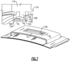
Figure 7 shows a portion of an exemplary blade outer air seal assembly. -
Figure 8A shows a method step of assembling a blade outer air seal assembly. -
Figure 8B shows a subsequent method step of assembling a blade outer air seal assembly. -
Figure 1 schematically illustrates agas turbine engine 20. Thegas turbine engine 20 is disclosed herein as a two-spool turbofan that generally incorporates afan section 22, acompressor section 24, a combustor section 26 and aturbine section 28. Thefan section 22 drives air along a bypass flow path B in a bypass duct defined within anacelle 15, and also drives air along a core flow path C for compression and communication into the combustor section 26 then expansion through theturbine section 28. Although depicted as a two-spool turbofan gas turbine engine in the disclosed non-limiting embodiment, it should be understood that the concepts described herein are not limited to use with two-spool turbofans as the teachings may be applied to other types of turbine engines including three-spool architectures. - The
exemplary engine 20 generally includes alow speed spool 30 and ahigh speed spool 32 mounted for rotation about an engine central longitudinal axis A relative to an enginestatic structure 36 viaseveral bearing systems 38. It should be understood thatvarious bearing systems 38 at various locations may alternatively or additionally be provided, and the location ofbearing systems 38 may be varied as appropriate to the application. - The
low speed spool 30 generally includes aninner shaft 40 that interconnects, a first (or low) pressure compressor 44 and a first (or low)pressure turbine 46. Theinner shaft 40 is connected to thefan 42 through a speed change mechanism, which in exemplarygas turbine engine 20 is illustrated as a gearedarchitecture 48 to drive afan 42 at a lower speed than thelow speed spool 30. Thehigh speed spool 32 includes anouter shaft 50 that interconnects a second (or high)pressure compressor 52 and a second (or high)pressure turbine 54. Acombustor 56 is arranged inexemplary gas turbine 20 between thehigh pressure compressor 52 and thehigh pressure turbine 54. Amid-turbine frame 57 of the enginestatic structure 36 may be arranged generally between thehigh pressure turbine 54 and thelow pressure turbine 46. Themid-turbine frame 57 further supports bearingsystems 38 in theturbine section 28. Theinner shaft 40 and theouter shaft 50 are concentric and rotate viabearing systems 38 about the engine central longitudinal axis A which is collinear with their longitudinal axes. - The core airflow is compressed by the low pressure compressor 44 then the
high pressure compressor 52, mixed and burned with fuel in thecombustor 56, then expanded over thehigh pressure turbine 54 andlow pressure turbine 46. Themid-turbine frame 57 includesairfoils 59 which are in the core airflow path C. Theturbines low speed spool 30 andhigh speed spool 32 in response to the expansion. It will be appreciated that each of the positions of thefan section 22,compressor section 24, combustor section 26,turbine section 28, and fandrive gear system 48 may be varied. For example,gear system 48 may be located aft of the low pressure compressor, or aft of the combustor section 26 or even aft ofturbine section 28, andfan 42 may be positioned forward or aft of the location ofgear system 48. - The
engine 20 in one example is a high-bypass geared aircraft engine. In a further example, theengine 20 bypass ratio is greater than about six, with an example embodiment being greater than about ten, the gearedarchitecture 48 is an epicyclic gear train, such as a planetary gear system or other gear system, with a gear reduction ratio of greater than about 2.3 and thelow pressure turbine 46 has a pressure ratio that is greater than about five. In one disclosed embodiment, theengine 20 bypass ratio is greater than about ten, the fan diameter is significantly larger than that of the low pressure compressor 44, and thelow pressure turbine 46 has a pressure ratio that is greater than about five.Low pressure turbine 46 pressure ratio is pressure measured prior to inlet oflow pressure turbine 46 as related to the pressure at the outlet of thelow pressure turbine 46 prior to an exhaust nozzle. The gearedarchitecture 48 may be an epicycle gear train, such as a planetary gear system or other gear system, with a gear reduction ratio of greater than about 2.3:1 and less than about 5:1. It should be understood, however, that the above parameters are only exemplary of one embodiment of a geared architecture engine and that the present invention is applicable to other gas turbine engines including direct drive turbofans. - A significant amount of thrust is provided by the bypass flow B due to the high bypass ratio. The
fan section 22 of theengine 20 is designed for a particular flight condition -- typically cruise at about 0.8 Mach and about 35,000 feet (10,668 meters). The flight condition of 0.8 Mach and 35,000 ft (10,668 meters), with the engine at its best fuel consumption - also known as "bucket cruise Thrust Specific Fuel Consumption ('TSFC')" - is the industry standard parameter of lbm of fuel being burned divided by lbf of thrust the engine produces at that minimum point. "Low fan pressure ratio" is the pressure ratio across the fan blade alone, without a Fan Exit Guide Vane ("FEGV") system. The low fan pressure ratio as disclosed herein according to one non-limiting embodiment is less than about 1.45. "Low corrected fan tip speed" is the actual fan tip speed in ft/sec divided by an industry standard temperature correction of [(Tram °R) / (518.7 °R)]0.5(where °R = K x 9/5). The "Low corrected fan tip speed" as disclosed herein according to one non-limiting embodiment is less than about 1150 ft / second (350.5 meters/second). -
Figure 2 shows a portion of aturbine section 28, which may be incorporated into a gas turbine engine such as the one shown inFigure 1 . However, it should be understood that other sections of thegas turbine engine 20 or other gas turbine engines, and even gas turbine engines not having a fan section at all, could benefit from this disclosure. - A
turbine blade 102 has a radiallyouter tip 103 that is spaced from a blade outerair seal assembly 104 with a blade outer air seal ("BOAS") 106. TheBOAS 106 may be made up of a plurality ofseal segments 105 that are circumferentially arranged in an annulus about the central axis A of theengine 20. TheBOAS seal segments 105 may be monolithic bodies that are formed of a high thermal-resistance, low-toughness material, such as a ceramic matrix composite ("CMC"). - The
BOAS 106 may be mounted to an engine case or structure, such as enginestatic structure 36 via a control ring orsupport structure 110. Theengine structure 36 may extend for a full 360° about the engine axis A. Theengine structure 36 may support thesupport structure 110 via a hook or other attachment means. -
Figures 3A-3D illustrate an exemplaryBOAS seal segment 105. As can be seen inFigure 3A , eachseal segment 105 is a body that defines radially inner and outer sides R1, R2, respectively, first and second axial sides A1, A2, respectively, and first and second circumferential sides C1, C2, respectively. The radially inner side R1 faces in a direction toward the engine central axis A. The radially inner side R1 is thus the gas path side of theseal segment 105 that bounds a portion of the core flow path C. The first axial side A1 faces in a forward direction toward the front of the engine 20 (i.e., toward the fan 42), and the second axial side A2 faces in an aft direction toward the rear of the engine 20 (i.e., toward the exhaust end). That is, the first axial side A1 corresponds to aleading edge 99, and the second axial side A2 corresponds to a trialingedge 101. - In the illustrated example, the
BOAS seal segment 105 includes a firstcircumferential wall 120 and a secondcircumferential wall 122 that extend radially outward from abase portion 124. Thebase portion 124 extends between theleading edge 99 and the trailingedge 101 and defines a gas path on a radially inner side and a non-gas path on a radially outer side. Anouter wall 126 extends between the first and secondcircumferential walls outer wall 126 includes a generally constant thickness and constant position in the radial direction such that an outer surface of theouter wall 126 is generally planar. In this disclosure, forward, aft, upstream, downstream, axial, radial, or circumferential is in relation to the engine axis A unless stated otherwise. Thebase portion 124 extends circumferentially outward of the first andsecond walls edges - The first
circumferential wall 120, the secondcircumferential wall 122, theouter wall 126, and thebase portion 124 of theBOAS seal segment 105 define apassage 128 for accepting thesupport structure 110. Thepassage 128 extends along theseal segment 105 in an axial direction. Theouter wall 126 includes aslot 130 for securing theBOAS seal segment 105 to thesupport structure 110. Theslot 130 prevents rotation of theBOAS seal segments 105 after assembly. In the illustrated embodiment, theslot 130 is rectangular. However, others slot shapes may come within the scope of this disclosure, such as round or oblong slots. Further, although asingle slot 130 is illustrated, multiple slots on asingle seal segment 105 may come within the scope of this disclosure. - As is shown in
Figure 4 , and with continuing reference toFigures 3A-3D , the second circumferential side C2 includes amating feature 140. Themating feature 140 extends radially outward from thebase portion 124. Themating feature 140 also extends circumferentially beyond the seal segment 105A to form a hook that engages with a neighboringseal segment 105B. Thismating feature 140 engages with anadjacent seal segment 105B in a "shiplap" manner. Themating feature 140 limits radial openings from the gas path. In further embodiments, a feather seal may be used in combination with themating feature 140 for sealing between circumferential ends C1, C2 ofadjacent seal segments 105A, 105B. - As shown in
Figure 3B , themating feature 140 has a width w1 in the axial direction that may be smaller than a width w2 of thebase portion 124 in the axial direction. In some embodiments, the width w1 is equal to the width w2. Theouter wall 126 has a width w3 in the axial direction. In an embodiment, the width w1 is about the same as the width w3. The outer wall width w3 is smaller than the base portion width w2. In an example, a ratio of the outer wall width w3 to the base portion width w2 is greater than about 0.5. In an embodiment, themating feature 140 has a thickness t1 that is the same as a thickness t2 of thebase portion 124. - As shown in further detail in
Figures 5A-5C , theBOAS 106 is formed of a ceramic matrix composite ("CMC") material. EachBOAS seal segment 105 is formed of a plurality of CMC laminates 142. Thelaminates 142 may be silicon carbide fibers, formed into a woven fabric in each layer. The fibers may be coated by a boron nitride. In other examples, theBOAS 106 may be made of a monolithic ceramic. - CMC components such as a
BOAS 106 are formed by laying fiber material, such as laminate sheets, in tooling, injecting a liquid resin into the tooling, and curing to form a solid composite component. The component may be densified by adding additional material to further stiffen the laminates. - In an embodiment, the
BOAS seal segment 105 is formed from two loops of CMC laminated plies. A center orfirst loop 144 defines thepassage 128. Thefirst loop 144 comprises the inner-most layers relative to thepassage 128. In one example embodiment, thefirst loop 144 is formed from four laminated plies 142. Thefirst loop 144 may be formed from laminates being wrapped around a core mandrel. Thesecond loop 146 is formed about thefirst loop 144. Thesecond loop 146 forms the outermost layers relative to thepassage 128. Thesecond loop 146 also forms the first and second circumferential sides C1, C2 circumferentially past the first andsecond walls second loop 146 is formed from four laminated plies 142. - In an example embodiment, the
BOAS seal segment 105 has a constant wall thickness of about 9 laminated plies, with each ply having a thickness of about 0.011 inches (0.279 mm). This structure may reduce thermal gradient stress. Although 9 laminated plies are illustrated, BOAS constructed of more or fewer plies may fall within the scope of this disclosure. - As shown in
Figure 5C , themating feature 140 on the second circumferential side C2 is formed of laminate plies 142. Themating feature 140 is formed of laminate plies 142 in thesecond loop 146. Themating feature 140 is integrally formed with thebase portion 124. - As shown in
Figures 6A-6B , theBOAS 106 is mounted to the engine via ansupport structure 110. Thesupport structure 110 extends circumferentially about the engine central axis A, and holds theBOAS 106 radially outward of theturbine blades 102. - The
support structure 110 has anattachment member 150 extending radially inward for engagement with theBOAS 106. Theattachment member 150 has anarrow portion 152 that extends radially inward, and first andsecond portions narrow portion 152, respectively. The first andsecond portions anti-rotation feature 155 that corresponds to the shape of theslot 130. For example, theanti-rotation feature 155 may be rectangular to fit within arectangular slot 130. Thestructure 110 has a plurality ofdiscrete attachment members 150 circumferentially spaced about thestructure 110. In an embodiment, there are an equal number ofattachment members 150 asBOAS seal segments 105. However, in some embodiments, aseal segment 105 may have more than oneslot 130, and thusadditional attachment members 150 may be used. - The
narrow portion 152 and first andsecond portions rings support structure 110 also has anaft hook 158 and aforward hook 160. Theforward hook 160 is axially forward of theattachment member 150, while the aft hook is axially aft of theattachment member 150. The aft and forward hooks 158, 160 are configured to engage with the retaining rings 180, 182. Thehooks hooks support structure 110. - The
support structure 110 may have anotch 174 on one of the forward and aft sides. Thenotch 174 ensures thesupport structure 110 cannot be installed backwards into theturbine section 28. - The
first retaining ring 180 has a radiallyinner portion 184 that engages thepassage 128 of theBOAS seal segment 105, and a radiallyouter portion 186 connected by aradially extending portion 188. The radiallyinner portion 184, radiallyouter portion 186, and radially extendingportion 188 generally form a "C" shape. Thesecond retaining ring 182 has the same shape. In one embodiment, a single part can be used for both the first and second retaining rings 180, 182. That is, a common part number is used, and the part is simply rotated and inserted from the opposite side. The retainingring - When the
BOAS 106 is assembled into thesupport structure 110 with the retaining rings 180, 182, a gap G may be formed between theBOAS seal segment 105 and thehooks support structure 110. The gap G is formed immediately radially outward of theupper wall 126 of theseal segment 105. This gap G is formed when the retaining rings 180, 182 are installed such that there is contact between the radiallyouter portions hooks - As shown in
Figure 7 , thesupport structure 110 has discrete radially inwardly extending portions. In this example, theportions second portions anti-rotation feature 155 that corresponds to the shape of theslot 130. The illustrated rectangularanti-rotation feature 155 has a distance d1 that is a length in the circumferential direction and a distance d2 that is a length in the axial direction. Theslot 130 has a length D1 in the circumferential direction and a length D2 in the axial direction. The distance d1 is slightly smaller than the length D1 and the distance d2 is slightly smaller than the length D2 to accommodate insertion of theanti-rotation feature 155 into theslot 130. - A method of assembling the
BOAS assembly 104 is illustrated inFigures 8A-8B . As shown, inFigure 8A , aBOAS seal segment 105 is moved radially onto thesupport structure 110. Theanti-rotation feature 155 fits into theslot 130. When moved into place, theanti-rotation feature 155 andnarrow portion 152 are entirely within thepassage 128. - Then, as shown in
Figure 8B , the retaining rings 180, 182 are axially moved into place. The retainingring 180 is moved axially forward and engages theBOAS seal segment 105 and thesupport structure 110 at an aft side. The retainingring 182 is moved axially aft and engages theBOAS seal segment 105 and thesupport structure 110 at a forward side. When the retaining rings 180, 182 are moved axially into place, the radiallyinner portions passage 128. The radiallyouter portions hooks support structure 110. - The retaining
ring 180 has an axiallyouter portion 196 with a notch 192 (shown inFigure 8B ). The retainingring 182 has an axiallyouter portion 198 with anotch 194. When the retaining rings 180, 182 are installed, the axiallyouter portions notches attachment member 150 of thesupport structure 110. That is, thefirst portion 154 fits into thenotch 194, while thesecond portion 156 fits into thenotch 192. - Known CMC BOAS require a large contact area with supports while also having few radial features to minimize thermal gradients. Known CMC BOAS may also require support designs that are complicated to manufacture. The disclosed hollow BOAS structure with an access slot allows for radial installation and retaining clips from both the front and back sides. This construction allows a larger contact area, permitting lower deflection and reduced stresses. The radial installation of the BOAS assembly allows each BOAS segment to have three or four attachment points, rather than two. This permits lower stresses because of increased contact area. This is particularly beneficial for ceramic BOAS because ceramic materials are not as ductile as metallic materials. The ability to use ceramic BOAS promotes a more stable assembly.
- Some known CMC BOAS have three or more radially protruding portions. The disclosed loop BOAS has the first and
second walls BOAS 106. The disclosed CMC BOAS has simple features that are easily manufactured using CMC laminates. - In this disclosure, "generally axially" means a direction having a vector component in the axial direction that is greater than a vector component in the circumferential direction, "generally radially" means a direction having a vector component in the radial direction that is greater than a vector component in the axial direction and "generally circumferentially" means a direction having a vector component in the circumferential direction that is greater than a vector component in the axial direction.
- Although an embodiment of this invention has been disclosed, a worker of ordinary skill in this art would recognize that certain modifications would come within the scope of this invention.
- For that reason, the following claims should be studied to determine the true scope and content of this invention.
Claims (15)
- A blade outer air seal segment (105; 105A; 105B), comprising:a base portion (124) extending between a first circumferential side (C1) and a second circumferential side (C2); anda first wall (120) circumferentially spaced from a second wall (122), the first and second walls (120, 122) extending radially outward from the base portion (124) and connected by an outer wall (126) to define a passage (128) extending in a generally axial direction along the base portion (124),characterised in thatthe second circumferential side (C2) has a mating feature (140) that extends generally radially outward from the base portion (124).
- The blade outer air seal segment (105; 105A; 105B) of claim 1, wherein the base portion (124) extends circumferentially outward of the first and second walls (120, 122).
- The blade outer air seal segment (105; 105A; 105B) of claim 1 or 2, wherein the mating feature (140) extends circumferentially beyond the base portion (124) to form a hook that is configured to engage with the first circumferential side (C1) of an adjacent blade outer air seal segment (105; 105A; 105B).
- The blade outer air seal segment (105; 105A; 105B) of any preceding claim, wherein the mating feature (140) has a width (W1) in the axial direction that is smaller than a width (W2) of the base portion (124).
- The blade outer air seal segment (105; 105A; 105B) of any preceding claim, wherein the blade outer air seal segment (105; 105A; 105B) is formed from a plurality of ceramic matrix composite laminates (142).
- The blade outer air seal segment (105; 105A; 105B) of any preceding claim, wherein the outer wall (126) has a slot (130).
- A turbine section (28) for a gas turbine engine (20), comprising:a turbine blade (102) extending radially outwardly to a radially outer tip (103) and for rotation about an axis of rotation (A); anda blade outer air seal (106) having a plurality of segments (105; 105A, 105B) mounted in a support structure (110) and arranged circumferentially about the axis of rotation (A) and radially outward of the outer tip (103), wherein each segment (105; 105A, 105B) has a first wall (120) circumferentially spaced from a second wall (122), the first and second walls (120, 122) joined by a base portion (124) and an outer wall (126) to define a passage (128) that extends axially along the segment (105; 105A, 105B),characterised in thateach segment (105; 105A, 105B) has a first and second circumferential side (C1, C2), and the second circumferential side (C2) has a mating feature (140) that extends generally radially outward from the base portion (124).
- The turbine section (28) of claim 7, wherein the outer wall (126) has a slot (130), and the support structure (110) is configured to engage the slot (130).
- The blade outer air seal (106) of claim 6 or turbine section (28) of claim 8, wherein the slot (130) is rectangular.
- The turbine section (28) of any of claims 7 to 9, wherein a portion (155) of the support structure (110) is within the passage (128).
- The turbine section (28) of any of claims 7 to 10, wherein the base portion (124) extends axially forward and aft of the outer wall (126) to define a leading edge (99) and a trailing edge (101).
- The turbine section (28) of any of claims 7 to 11, wherein the mating feature (140) of each segment (105; 105A, 105B) engages with the first circumferential side (C1) of an adjacent segment (105; 105B, 105A).
- The turbine section (28) of any of claims 7 to 12, wherein the blade outer air seal (106) is formed from a ceramic matrix composite.
- The blade outer air seal segment (105; 105A; 105B) of any of claims 1 to 6 or turbine section (28) of any of claims 7 to 13, wherein the outer wall (126) has a width (W3) in the axial direction that is smaller than a width (W2) of the base portion (124) in the axial direction.
- The blade outer air seal segment (105; 105A; 105B) or turbine section (28) of claim 14, wherein a ratio of the outer wall width (W3) to the base portion width (W2) is greater than 0.5.
Applications Claiming Priority (1)
| Application Number | Priority Date | Filing Date | Title |
|---|---|---|---|
| US16/210,215 US10934878B2 (en) | 2018-12-05 | 2018-12-05 | CMC loop boas |
Publications (2)
| Publication Number | Publication Date |
|---|---|
| EP3663531A1 EP3663531A1 (en) | 2020-06-10 |
| EP3663531B1 true EP3663531B1 (en) | 2023-05-03 |
Family
ID=68808004
Family Applications (1)
| Application Number | Title | Priority Date | Filing Date |
|---|---|---|---|
| EP19213872.5A Active EP3663531B1 (en) | 2018-12-05 | 2019-12-05 | Blade outer air seal segment and turbine section |
Country Status (2)
| Country | Link |
|---|---|
| US (1) | US10934878B2 (en) |
| EP (1) | EP3663531B1 (en) |
Families Citing this family (2)
| Publication number | Priority date | Publication date | Assignee | Title |
|---|---|---|---|---|
| US10934878B2 (en) * | 2018-12-05 | 2021-03-02 | Raytheon Technologies Corporation | CMC loop boas |
| US11098608B2 (en) * | 2019-03-13 | 2021-08-24 | Raytheon Technologies Corporation | CMC BOAS with internal support structure |
Family Cites Families (26)
| Publication number | Priority date | Publication date | Assignee | Title |
|---|---|---|---|---|
| US6884026B2 (en) * | 2002-09-30 | 2005-04-26 | General Electric Company | Turbine engine shroud assembly including axially floating shroud segment |
| JP5569194B2 (en) | 2010-07-02 | 2014-08-13 | 株式会社Ihi | Method for manufacturing shroud segment |
| US8834105B2 (en) * | 2010-12-30 | 2014-09-16 | General Electric Company | Structural low-ductility turbine shroud apparatus |
| US9169739B2 (en) * | 2012-01-04 | 2015-10-27 | United Technologies Corporation | Hybrid blade outer air seal for gas turbine engine |
| CA2806401A1 (en) | 2012-02-22 | 2013-08-22 | General Electric Company | Low-ductility turbine shroud |
| US8814507B1 (en) * | 2013-05-28 | 2014-08-26 | Siemens Energy, Inc. | Cooling system for three hook ring segment |
| WO2015031764A1 (en) | 2013-08-29 | 2015-03-05 | United Technologies Corporation | Blade outer air seal made of ceramic matrix composite |
| US10385718B2 (en) | 2015-06-29 | 2019-08-20 | Rolls-Royce North American Technologies, Inc. | Turbine shroud segment with side perimeter seal |
| US10094234B2 (en) * | 2015-06-29 | 2018-10-09 | Rolls-Royce North America Technologies Inc. | Turbine shroud segment with buffer air seal system |
| US10132194B2 (en) * | 2015-12-16 | 2018-11-20 | Rolls-Royce North American Technologies Inc. | Seal segment low pressure cooling protection system |
| US10480108B2 (en) | 2017-03-01 | 2019-11-19 | Rolls-Royce Corporation | Ceramic matrix composite components reinforced for managing multi-axial stresses and methods for fabricating the same |
| US10801349B2 (en) * | 2017-08-25 | 2020-10-13 | Raytheon Technologies Corporation | Ceramic matrix composite blade outer air seal |
| US10689997B2 (en) * | 2018-04-17 | 2020-06-23 | Raytheon Technologies Corporation | Seal assembly for gas turbine engine |
| US10801351B2 (en) * | 2018-04-17 | 2020-10-13 | Raytheon Technologies Corporation | Seal assembly for gas turbine engine |
| US11085316B2 (en) * | 2018-08-22 | 2021-08-10 | Raytheon Technologies Corporation | Blade outer air seal formed of laminate and having radial support hooks |
| US11400624B2 (en) * | 2018-09-24 | 2022-08-02 | Raytheon Technologies Corporation | Constant cross section mandrel for CMC components |
| US10927710B2 (en) * | 2018-09-26 | 2021-02-23 | Raytheon Technologies Corporation | Blade outer air seal laminate T-joint |
| US11008894B2 (en) * | 2018-10-31 | 2021-05-18 | Raytheon Technologies Corporation | BOAS spring clip |
| US10934877B2 (en) * | 2018-10-31 | 2021-03-02 | Raytheon Technologies Corporation | CMC laminate pocket BOAS with axial attachment scheme |
| US10968761B2 (en) * | 2018-11-08 | 2021-04-06 | Raytheon Technologies Corporation | Seal assembly with impingement seal plate |
| US11187100B2 (en) * | 2018-12-03 | 2021-11-30 | Raytheon Technologies Corporation | CMC honeycomb base for abradable coating on CMC BOAS |
| US10934878B2 (en) * | 2018-12-05 | 2021-03-02 | Raytheon Technologies Corporation | CMC loop boas |
| US10914186B2 (en) * | 2018-12-05 | 2021-02-09 | Raytheon Technologies Corporation | BOAS control structure with center support hook |
| US10753221B2 (en) * | 2018-12-12 | 2020-08-25 | Raytheon Technologies Corporation | Seal assembly with ductile wear liner |
| US10815810B2 (en) * | 2019-01-10 | 2020-10-27 | Raytheon Technologies Corporation | BOAS assemblies with axial support pins |
| US11085332B2 (en) * | 2019-01-16 | 2021-08-10 | Raytheon Technologies Corporation | BOAS retention assembly with interlocking ring structures |
-
2018
- 2018-12-05 US US16/210,215 patent/US10934878B2/en active Active
-
2019
- 2019-12-05 EP EP19213872.5A patent/EP3663531B1/en active Active
Also Published As
| Publication number | Publication date |
|---|---|
| US10934878B2 (en) | 2021-03-02 |
| US20200182077A1 (en) | 2020-06-11 |
| EP3663531A1 (en) | 2020-06-10 |
Similar Documents
| Publication | Publication Date | Title |
|---|---|---|
| EP3779131B1 (en) | Flow path component assembly and corresponding turbine section for a gas turbine engine | |
| EP3792453A2 (en) | Cmc boas assembly | |
| EP3786419A1 (en) | Ceramic matrix composite boas arrangement | |
| EP3734021B1 (en) | Blade outer air seal assembly | |
| EP3663531B1 (en) | Blade outer air seal segment and turbine section | |
| EP3739168B1 (en) | Gas turbine boas assembly and method | |
| EP3767075A1 (en) | Assembly with blade outer air seal formed of ceramic matrix composite | |
| EP3708785B1 (en) | Boas assembly having a seal carrier with dovetail attachments | |
| EP3719263A1 (en) | Blade outer air seal assembly with intersegment seal | |
| EP3719264A1 (en) | Cmc boas with transverse hook arrangement | |
| EP3636885B1 (en) | Turbine section for a gas turbine engine and method of manufacturing a blade outer air seal | |
| EP3663532B1 (en) | Boas control structure with center support hook | |
| EP3722569A1 (en) | Blade outer air seal and turbine section | |
| EP3708786A2 (en) | Cmc boas with internal support structure | |
| EP3712384B1 (en) | Blade outer air seal with seal carrier | |
| EP3712382B1 (en) | Blade outer air seal assembly with wear liner | |
| EP3792454B1 (en) | Intersegment seal for cmc boas assembly | |
| EP3767077B1 (en) | Cmc boas arrangement | |
| EP3767076A1 (en) | Assembly with blade outer air seal formed of ceramic matrix composite | |
| EP3712383A1 (en) | Cmc blade outer air seal | |
| EP3767078A1 (en) | Cmc boas arrangement |
Legal Events
| Date | Code | Title | Description |
|---|---|---|---|
| PUAI | Public reference made under article 153(3) epc to a published international application that has entered the european phase |
Free format text: ORIGINAL CODE: 0009012 |
|
| STAA | Information on the status of an ep patent application or granted ep patent |
Free format text: STATUS: THE APPLICATION HAS BEEN PUBLISHED |
|
| AK | Designated contracting states |
Kind code of ref document: A1 Designated state(s): AL AT BE BG CH CY CZ DE DK EE ES FI FR GB GR HR HU IE IS IT LI LT LU LV MC MK MT NL NO PL PT RO RS SE SI SK SM TR |
|
| AX | Request for extension of the european patent |
Extension state: BA ME |
|
| STAA | Information on the status of an ep patent application or granted ep patent |
Free format text: STATUS: REQUEST FOR EXAMINATION WAS MADE |
|
| 17P | Request for examination filed |
Effective date: 20201210 |
|
| RBV | Designated contracting states (corrected) |
Designated state(s): AL AT BE BG CH CY CZ DE DK EE ES FI FR GB GR HR HU IE IS IT LI LT LU LV MC MK MT NL NO PL PT RO RS SE SI SK SM TR |
|
| RAP1 | Party data changed (applicant data changed or rights of an application transferred) |
Owner name: RAYTHEON TECHNOLOGIES CORPORATION |
|
| RIC1 | Information provided on ipc code assigned before grant |
Ipc: F01D 25/24 20060101ALI20220902BHEP Ipc: F01D 11/08 20060101AFI20220902BHEP |
|
| GRAP | Despatch of communication of intention to grant a patent |
Free format text: ORIGINAL CODE: EPIDOSNIGR1 |
|
| STAA | Information on the status of an ep patent application or granted ep patent |
Free format text: STATUS: GRANT OF PATENT IS INTENDED |
|
| INTG | Intention to grant announced |
Effective date: 20221214 |
|
| GRAS | Grant fee paid |
Free format text: ORIGINAL CODE: EPIDOSNIGR3 |
|
| GRAA | (expected) grant |
Free format text: ORIGINAL CODE: 0009210 |
|
| STAA | Information on the status of an ep patent application or granted ep patent |
Free format text: STATUS: THE PATENT HAS BEEN GRANTED |
|
| AK | Designated contracting states |
Kind code of ref document: B1 Designated state(s): AL AT BE BG CH CY CZ DE DK EE ES FI FR GB GR HR HU IE IS IT LI LT LU LV MC MK MT NL NO PL PT RO RS SE SI SK SM TR |
|
| REG | Reference to a national code |
Ref country code: GB Ref legal event code: FG4D |
|
| REG | Reference to a national code |
Ref country code: AT Ref legal event code: REF Ref document number: 1564755 Country of ref document: AT Kind code of ref document: T Effective date: 20230515 Ref country code: CH Ref legal event code: EP |
|
| REG | Reference to a national code |
Ref country code: DE Ref legal event code: R096 Ref document number: 602019028319 Country of ref document: DE |
|
| REG | Reference to a national code |
Ref country code: IE Ref legal event code: FG4D |
|
| P01 | Opt-out of the competence of the unified patent court (upc) registered |
Effective date: 20230603 |
|
| REG | Reference to a national code |
Ref country code: LT Ref legal event code: MG9D |
|
| REG | Reference to a national code |
Ref country code: NL Ref legal event code: MP Effective date: 20230503 |
|
| REG | Reference to a national code |
Ref country code: AT Ref legal event code: MK05 Ref document number: 1564755 Country of ref document: AT Kind code of ref document: T Effective date: 20230503 |
|
| PG25 | Lapsed in a contracting state [announced via postgrant information from national office to epo] |
Ref country code: SE Free format text: LAPSE BECAUSE OF FAILURE TO SUBMIT A TRANSLATION OF THE DESCRIPTION OR TO PAY THE FEE WITHIN THE PRESCRIBED TIME-LIMIT Effective date: 20230503 Ref country code: PT Free format text: LAPSE BECAUSE OF FAILURE TO SUBMIT A TRANSLATION OF THE DESCRIPTION OR TO PAY THE FEE WITHIN THE PRESCRIBED TIME-LIMIT Effective date: 20230904 Ref country code: NO Free format text: LAPSE BECAUSE OF FAILURE TO SUBMIT A TRANSLATION OF THE DESCRIPTION OR TO PAY THE FEE WITHIN THE PRESCRIBED TIME-LIMIT Effective date: 20230803 Ref country code: NL Free format text: LAPSE BECAUSE OF FAILURE TO SUBMIT A TRANSLATION OF THE DESCRIPTION OR TO PAY THE FEE WITHIN THE PRESCRIBED TIME-LIMIT Effective date: 20230503 Ref country code: ES Free format text: LAPSE BECAUSE OF FAILURE TO SUBMIT A TRANSLATION OF THE DESCRIPTION OR TO PAY THE FEE WITHIN THE PRESCRIBED TIME-LIMIT Effective date: 20230503 Ref country code: AT Free format text: LAPSE BECAUSE OF FAILURE TO SUBMIT A TRANSLATION OF THE DESCRIPTION OR TO PAY THE FEE WITHIN THE PRESCRIBED TIME-LIMIT Effective date: 20230503 |
|
| RAP4 | Party data changed (patent owner data changed or rights of a patent transferred) |
Owner name: RTX CORPORATION |
|
| PG25 | Lapsed in a contracting state [announced via postgrant information from national office to epo] |
Ref country code: RS Free format text: LAPSE BECAUSE OF FAILURE TO SUBMIT A TRANSLATION OF THE DESCRIPTION OR TO PAY THE FEE WITHIN THE PRESCRIBED TIME-LIMIT Effective date: 20230503 Ref country code: PL Free format text: LAPSE BECAUSE OF FAILURE TO SUBMIT A TRANSLATION OF THE DESCRIPTION OR TO PAY THE FEE WITHIN THE PRESCRIBED TIME-LIMIT Effective date: 20230503 Ref country code: LV Free format text: LAPSE BECAUSE OF FAILURE TO SUBMIT A TRANSLATION OF THE DESCRIPTION OR TO PAY THE FEE WITHIN THE PRESCRIBED TIME-LIMIT Effective date: 20230503 Ref country code: LT Free format text: LAPSE BECAUSE OF FAILURE TO SUBMIT A TRANSLATION OF THE DESCRIPTION OR TO PAY THE FEE WITHIN THE PRESCRIBED TIME-LIMIT Effective date: 20230503 Ref country code: IS Free format text: LAPSE BECAUSE OF FAILURE TO SUBMIT A TRANSLATION OF THE DESCRIPTION OR TO PAY THE FEE WITHIN THE PRESCRIBED TIME-LIMIT Effective date: 20230903 Ref country code: HR Free format text: LAPSE BECAUSE OF FAILURE TO SUBMIT A TRANSLATION OF THE DESCRIPTION OR TO PAY THE FEE WITHIN THE PRESCRIBED TIME-LIMIT Effective date: 20230503 Ref country code: GR Free format text: LAPSE BECAUSE OF FAILURE TO SUBMIT A TRANSLATION OF THE DESCRIPTION OR TO PAY THE FEE WITHIN THE PRESCRIBED TIME-LIMIT Effective date: 20230804 |
|
| PG25 | Lapsed in a contracting state [announced via postgrant information from national office to epo] |
Ref country code: FI Free format text: LAPSE BECAUSE OF FAILURE TO SUBMIT A TRANSLATION OF THE DESCRIPTION OR TO PAY THE FEE WITHIN THE PRESCRIBED TIME-LIMIT Effective date: 20230503 |
|
| PG25 | Lapsed in a contracting state [announced via postgrant information from national office to epo] |
Ref country code: SK Free format text: LAPSE BECAUSE OF FAILURE TO SUBMIT A TRANSLATION OF THE DESCRIPTION OR TO PAY THE FEE WITHIN THE PRESCRIBED TIME-LIMIT Effective date: 20230503 |
|
| PGFP | Annual fee paid to national office [announced via postgrant information from national office to epo] |
Ref country code: GB Payment date: 20231121 Year of fee payment: 5 |
|
| PG25 | Lapsed in a contracting state [announced via postgrant information from national office to epo] |
Ref country code: SM Free format text: LAPSE BECAUSE OF FAILURE TO SUBMIT A TRANSLATION OF THE DESCRIPTION OR TO PAY THE FEE WITHIN THE PRESCRIBED TIME-LIMIT Effective date: 20230503 Ref country code: SK Free format text: LAPSE BECAUSE OF FAILURE TO SUBMIT A TRANSLATION OF THE DESCRIPTION OR TO PAY THE FEE WITHIN THE PRESCRIBED TIME-LIMIT Effective date: 20230503 Ref country code: RO Free format text: LAPSE BECAUSE OF FAILURE TO SUBMIT A TRANSLATION OF THE DESCRIPTION OR TO PAY THE FEE WITHIN THE PRESCRIBED TIME-LIMIT Effective date: 20230503 Ref country code: EE Free format text: LAPSE BECAUSE OF FAILURE TO SUBMIT A TRANSLATION OF THE DESCRIPTION OR TO PAY THE FEE WITHIN THE PRESCRIBED TIME-LIMIT Effective date: 20230503 Ref country code: DK Free format text: LAPSE BECAUSE OF FAILURE TO SUBMIT A TRANSLATION OF THE DESCRIPTION OR TO PAY THE FEE WITHIN THE PRESCRIBED TIME-LIMIT Effective date: 20230503 Ref country code: CZ Free format text: LAPSE BECAUSE OF FAILURE TO SUBMIT A TRANSLATION OF THE DESCRIPTION OR TO PAY THE FEE WITHIN THE PRESCRIBED TIME-LIMIT Effective date: 20230503 |
|
| PGFP | Annual fee paid to national office [announced via postgrant information from national office to epo] |
Ref country code: FR Payment date: 20231122 Year of fee payment: 5 Ref country code: DE Payment date: 20231121 Year of fee payment: 5 |
|
| REG | Reference to a national code |
Ref country code: DE Ref legal event code: R097 Ref document number: 602019028319 Country of ref document: DE |
|
| PLBE | No opposition filed within time limit |
Free format text: ORIGINAL CODE: 0009261 |
|
| STAA | Information on the status of an ep patent application or granted ep patent |
Free format text: STATUS: NO OPPOSITION FILED WITHIN TIME LIMIT |
|
| 26N | No opposition filed |
Effective date: 20240206 |