EP3033464B1 - Device with push-push mechanism - Google Patents
Device with push-push mechanism Download PDFInfo
- Publication number
- EP3033464B1 EP3033464B1 EP14733594.7A EP14733594A EP3033464B1 EP 3033464 B1 EP3033464 B1 EP 3033464B1 EP 14733594 A EP14733594 A EP 14733594A EP 3033464 B1 EP3033464 B1 EP 3033464B1
- Authority
- EP
- European Patent Office
- Prior art keywords
- receptacle
- component
- locking part
- guide
- locking
- Prior art date
- Legal status (The legal status is an assumption and is not a legal conclusion. Google has not performed a legal analysis and makes no representation as to the accuracy of the status listed.)
- Active
Links
Images


Classifications
-
- E—FIXED CONSTRUCTIONS
- E05—LOCKS; KEYS; WINDOW OR DOOR FITTINGS; SAFES
- E05C—BOLTS OR FASTENING DEVICES FOR WINGS, SPECIALLY FOR DOORS OR WINDOWS
- E05C19/00—Other devices specially designed for securing wings, e.g. with suction cups
- E05C19/02—Automatic catches, i.e. released by pull or pressure on the wing
- E05C19/022—Released by pushing in the closing direction
-
- B—PERFORMING OPERATIONS; TRANSPORTING
- B60—VEHICLES IN GENERAL
- B60N—SEATS SPECIALLY ADAPTED FOR VEHICLES; VEHICLE PASSENGER ACCOMMODATION NOT OTHERWISE PROVIDED FOR
- B60N3/00—Arrangements or adaptations of other passenger fittings, not otherwise provided for
- B60N3/10—Arrangements or adaptations of other passenger fittings, not otherwise provided for of receptacles for food or beverages, e.g. refrigerated
Definitions
- a make-up mirror light for installation in a vehicle roof which has a mirror flap and a housing part.
- the mirror flap is arranged adjustable by means of a pivot bearing on the housing part from a pivoted-use position into a pivoted-rest position against the restoring force of their weight.
- a locking device is provided, which has a locking element with a latch, which can be moved along a latching cam track and brought into a latching position.
- the locking device further has on one assembly a transverse or perpendicular to the direction of insertion of the guide cam slidable cross slide.
- the latching cam track is arranged on the transverse slide and designed as an edge-open heart cam with one of the other module facing insertion opening for the bolt.
- WO 2013/022907 A1 discloses a pressure-locking mechanism having a housing and a latch body that is movable relative to the housing and has a track.
- a driver is disposed in a housing slot, the driver being connected to a pin extending outwardly from the driver and engaging the track so that the pin moves along the track as the driver moves along the slot emotional.
- a biasing spring may be disposed between a counterweight and an axis of rotation for a pivotable hammer such that the biasing spring urges the lever arm and the counterweight toward the locking body.
- a locking element which is arranged on a first component, guided in a heart curve, which is arranged on a second component.
- the locking element therefore essentially corresponds to a hook, which engages behind a recess in order to keep at least the first or second component in the closed position.
- the object of the present invention is therefore to provide a device with a mechanism for moving a component from an open to a closed state and vice versa, wherein the device requires a small space and reliable locking and unlocking provides.
- a receptacle, a component receptacle and a locking part which slidably mounted in the receptacle and protrudes in an open state of the component by a first width of the receptacle and protrudes in a closed state by a second width of the receptacle and is received in the component receptacle, wherein the second width is greater than the first width wherein the locking member is received against the force of a spring means in the receptacle and the locking member has a heart cam in which a guide member is slidably mounted, which is transversely displaceable to the direction of displacement of the locking part, and wherein the locking member on the side facing away from the receptacle Slant and the component holder have a corresponding slope, which abut each other in the closed state of the component and are mutually displaceable, wherein a first
- the device has the advantage over known "push-push” mechanisms that it only requires a small amount of space.
- no ab- or projecting part is arranged on the component, which is pivoted or otherwise opened, which engages in a locking device.
- the component has only one component receptacle, which has a bevel.
- the component receptacle has a first edge and a second edge, from which the component receptacle extends into the component.
- the first edge and the second edge are offset relative to one another, so that the locking part is brought into the receptacle in the closed state of the component with a pressure on the component over the first edge, which protrudes further in the direction of the locking part than the second edge, wherein the locking member is held over the heart cam in a position in which the locking member protrudes a first distance from the recording.
- the component can be opened because the locking member protrudes only by the first width of the receptacle, which allows a displacement of the component, since the locking member does not come into contact with the second edge in this position, the less far in the direction of the locking part the receptacle protrudes as the first edge.
- the component is moved in the direction of the locking part.
- the second edge of the component passes through the locking member without contacting the locking member because the locking member protrudes only about the first width of the receptacle and the second edge has a greater distance from the receptacle and the locking member than the first edge.
- the first edge presses on passing the locking member, the locking member further into the receptacle, wherein on the heart cam, the locking member is unlocked and is moved over the spring means of the receptacle. After the first edge has passed the locking member, no pressure is exerted on the component, so that the locking member is moved into the component holder and locks the component.
- the locking member which has a corresponding slope to the slope of the component receiving, is pushed to spend in the open state of the component in the receptacle and for locking the component engages the locking member in the component receptacle, wherein the two slopes abut each other. If, in the closed state of the component, pressure is exerted on the component, essentially in the area of the component receptacle, then the locking part slides along the slope of the component receptacle into the receptacle until the component is no longer held by the locking part. After the component has been moved to the open state, stands the locking member by a first distance from the recording forth.
- the spring device causes the locking part to move at least so far that it protrudes from the receptacle by a certain amount.
- the widths by which the locking part protrudes from the receptacle are determined by the guide element and the heart curve.
- the heart curve has areas in which the guide element can be held in different positions. This determines the position of the locking part.
- the component passes through the locking member until the first edge presses the locking member into the receptacle, the locking member is unlocked and the locking member is pressed via the spring means from the receptacle in the component holder. Subsequently, the component is held in this locked state by the locking member. If a pressure is exerted on the component again, then the locking part is pushed into the receptacle and released the component.
- the present invention not only the heart curve, which is introduced on an upper side in the locking part, displaceable, but also the guide element.
- the slope of the component receptacle and the slope of the locking member are formed so that the slope of the locking member, in particular in the direction of the component in the open state, decreases, and the slope of the component receptacle in the direction of Locking part increases according to the configuration of the slope of the locking part.
- the device may further comprise a transverse to the direction of displacement of the locking member extending guide, in which the guide element is displaceable.
- the guide ensures that the guide element does not tilt when displaced transversely to the direction of displacement of the locking part and blocks the device.
- the displaceable transversely to the direction of displacement of the locking member guide member allows an embodiment of the device, wherein the locking member is moved only along a direction of displacement and abut the sides of the locking member on the side walls which define and define the recording.
- the spring device may have at least one compression spring.
- other spring means can be used in the context of the invention, which endeavor to push the locking member from the receptacle.
- the spring device has at least two permanent magnets, wherein a permanent magnet in the receptacle and the other permanent magnet disposed on the locking member and the permanent magnets are aligned with each other so that they repel each other.
- Such an embodiment therefore comprises two permanent magnets, which take over the task of the spring device.
- the device may in other embodiments comprise an electromagnet, wherein the locking part is made of a magnetic metal and the locking part is movable by the electromagnet into the receptacle when the electromagnet is activated.
- an opening and closing of the component or a movement of the component in the open and closed state carried out electrically.
- an operating element can be actuated or another control device operated, which effect a displacement of the locking part due to the electromagnet against the force of a spring (spring device).
- the guide element is a pin.
- a first end of the pin is in the heart cam and the second end of the pin is slidably mounted in the transverse guide.
- the guide element may also be formed as a ball, according to the selected embodiment, the guide and the Herkurve are formed accordingly.
- a guide element which is designed as a ball, has the advantage over other forms that the friction is significantly reduced.
- a heart curve and a corresponding Provide guide element on both sides of the locking part are, for example, metal balls and if the locking part is also made of metal, there are fields of application for devices according to the invention which hitherto could not be realized with systems comprising a heart curve. For this purpose, for example, door closures are mentioned. Such systems are very robust. Other materials may be used instead of metals for the constituents of the device.
- the pin between the first end and the second end may have a surrounding plate which is slidably mounted on a clearance between the receptacle and the locking member.
- a surrounding plate in these embodiments rests on the locking member with the first end of the pin received in the heart cam.
- the locking member, the guide member and / or the receptacle may consist of a plastic and / or metal.
- Plastic parts are easy to produce by injection molding and reduce the cost of manufacturing the device and the overall cost of the device.
- Metal parts ensure a robust finish of the device.
- the locking part may comprise on at least one side guide means, via which the locking part is displaceable on at least one corresponding guide means of the receptacle. About the guide means will prevents tilting of the locking part.
- the guide means may also be surface coated with a friction reducing material or formed so that the surface of the guide means is friction reducing (eg structure).
- the slope of the locking part with respect to a displacement plane at an angle of 15 ° to 50 ° (in particular in the range of 45 °).
- the angle is dependent on the second width of the portion of the locking part, which protrudes from the receptacle in the closed state of the component, and of further dimensions of the device, as well as the dimensions of the component. It can also be provided significantly steeper angle, in which case the region of the locking part, which protrudes from the receptacle in the closed state of the component, has a smaller size.
- the guide element may also be connected to a bracket, which is displaceable along and transversely to a rear part bounding the receptacle.
- Fig. 1 shows a perspective view of a device 10 with a "push-push” mechanism in a schematic representation.
- the facility is in the in Fig. 1 embodiment shown part of a locking device for a pivotable device, which has, for example, a tray or a tray.
- a flap 80 has a component 70, wherein the component 70 is an integral part of the flap 80.
- the component 70 has a component receptacle 16.
- the component receptacle 16 extends beyond the component 70 up to a first edge 82.
- the component receptacle 16 extends to a second edge 84.
- the first edge 82 extends offset the second edge 84.
- the first edge 82 has a distance d to the second edge 84.
- the flap 80 is pivotable about an axis, not shown. This axis is located to the left of the component 70.
- a locking part 12 is accommodated in the component receptacle 16.
- the locking part 12 is mounted in a receptacle 14.
- the receptacle 14 has guides 30.
- the locking member 12 has guide rails 28 which are received in the guides 30. About the guide rails 28, the locking member is guided displaceably in the receptacle 14.
- the component holder 16 has a bevel 42 and the locking part 12 has a corresponding slope 40.
- the locking part 12 has two openings 86, in which springs (in Fig. 1 not shown), which endeavor to push the locking member 12 out of the receptacle 14.
- the locking member has a heart cam 18 in which a pin 92 (in Fig. 1 not shown). The pin 92 is arranged so that it can only be displaced parallel to the edges 82 and 84.
- the locking part 12 is pushed into the receptacle 14 against the force of the springs.
- the pin 92 (see Fig. 2a - 2k ) moved from an abutment position in the heart cam 18 in a locking position.
- the locking member 12 protrudes by a first width W 1 from the receptacle 14.
- the flap 80 can then fold down or be moved because the second edge 84 does not come into contact with it as it passes the latch member 12.
- the flap 80 If the flap 80 to be closed and locked again, the flap 80 is pressed from below against the locking member 12, wherein the second edge 84, the locking member 12 passes without contact to this. If the flap 80 is pushed further upwards, the first edge 82 passes through the locking part 12 and pushes the locking part 12 into the receptacle 14, since the locking part projects out of the receptacle 14 by the first width W 1 . The pin 92 is thereby moved out of its abutment position and releases a displacement of the locking part 12, the locking part 12 being pressed by the springs out of the receptacle 14 and entering the component receptacle 16. Thereafter, the flap 80 is again locked by the device 10 and can be unlocked by pressing again from below.
- Fig. 2a - 2k show a schematic representation of the displacement of the elements of a device with a "push-push” mechanism.
- the locking member 12 is also slidably mounted via guide means in the receptacle 14.
- the receptacle 14 is in the Fig. 2a-k only partially and schematically shown.
- the locking part 12 projects into Fig. 2a around a second width W 2 out of the receptacle 14 and thus blocks a pivoting of the component 70 about a pivot point or axis of rotation located to the left of the component 70.
- the receptacle 14 has at its lower portions slopes 52 which are intended to prevent the component 70 abuts when opening or closing on the receptacle 14 or blocked by the receptacle 14.
- the locking member 12 has at its top 32 (see Fig. 1 . 3 - 5 ) has a heart curve 18.
- a pin 92 is guided, which along a guide plate 50 (see Fig. 3-5 ) is orthogonal to the longitudinal axis of the locking member 12 displaced.
- a cover can be arranged above the receptacle 14, which limits a pivoting of the component 70 upwards in the direction of the arrows 88.
- the heart curve 18 and the position of the pin 92 in the heart curve 18 are shown schematically.
- the position of the pin 92 substantially corresponds to the position of the locking part 12 in the receptacle 14.
- Fig. 2a is the component 70 in a locked state.
- the locking part 12 protrudes around the second width W 2 from the receptacle 14 and is received in the component receptacle 16.
- the pin 92 is in the position shown.
- Fig. 2c is the pin 92 at an end point, which prevents further displacement of the locking member 12 in the receptacle 14.
- the pressure is applied to the component 70, wherein the locking member 12 moves by the spring in the direction of the arrow 94 to the left ( Fig. 2d ). Since the second edge 84 of the component receptacle 16 does not protrude as far in the direction of the receptacle 14 as the first edge 82 and after the locking part 12 is no longer received in the component receptacle 16, the component 70 moves downward in the direction of the arrow 96. The pin 92 is in the position shown.
- Fig. 2e the locking member 12 is in an unlocked position and is held in this position by the pin 92, wherein the component 70 is further moved downwards and thus opened.
- the locking member 12 protrudes in the unlocked position by a first width W 1 from the receptacle 14 out.
- the locking part 12 is between the Fig. 2c to 2e has been moved by a small amount by the spring out of the receptacle 14 out. However, it is ensured by the first width W 1 that the second edge 84 of the component holder 16 does not come into contact with the locking part 12 when passing through the locking part 12.
- Fig. 2h the maximum swung out state of the component 70 is shown at the top.
- the locking member 12 is received so far in the receptacle 14 that it can not be pushed further into the receptacle 14.
- the pin 92 which is located in a further end position, a further insertion is prevented.
- the locking part 12 is pushed further out of the receptacle 14 by the spring in the direction of the arrow 94, the locking part 12 being moved into the component receptacle 16 ( Fig. 2j ).
- the pin 92 is located in the position shown.
- Fig. 2k the locked state of the component 70 is shown, which corresponds to the state of Fig. 2a equivalent.
- FIG. 3 shows an exploded view of a second embodiment with a "push-push” mechanism.
- a device 10 has a locking part 12, which is accommodated in a receptacle 14 and can engage in a component receptacle 16.
- the recording 14 is in Fig. 3 formed by two side parts 72 and a rear part 74.
- the receptacle 14 may, for example, be part of a frame surrounding a compartment, the component 70 being a flap for closing the compartment.
- the receptacle 14 may also be integrated in other devices, which cooperates with a component 70, which may also be designed differently.
- the side parts 72 and the rear part 74 can accordingly be integrated in a frame or be parts of the frame.
- the component receptacle 16 is introduced in a schematically indicated component 70.
- the side parts 72 each have a guide 30 on the inside of the sides 62 which bound the receptacle 14.
- the guide 30 is in each case designed such that guide rails 28 of the locking part 12 accommodated in the guide 30 can be displaced, but the locking part 12 can not be completely moved out of the receptacle 14 in the assembled state.
- the rear wall 56 of the rear part 74 has an opening 44, in which a spring 26 is partially received. The opposite end of the spring 26 is pushed onto a pin 46.
- the pin 46 is located on the back 58 of the locking part 12.
- the guide rails 28 (in Fig. 3 only a guide bar 28 shown) are located on the opposite sides 60 of the locking member 12. The locking member 12 is pushed out via the spring 26 of the receptacle 14, but is on the guides 30 and the guide rails 28 always held in the receptacle 14.
- the side parts 72 further have bulges 48, in which openings 64 are introduced.
- a guide plate 50 is inserted so that the openings 64 of the recesses 48 are aligned with openings 66 of a guide plate 50.
- the guide plate 50 can be connected to the side parts 72, for example by means of screws or bolts.
- a guide member 20 is placed on the locking member 12 so that a lower pin-shaped end engages in the introduced on the surface 32 of the locking member 12 heart cam 18.
- the surrounding the guide member 20 plate 24 is located with its lower surface on the surface 32 of the locking member 12.
- the upper end 34 of the pin-shaped in this section guide member 20 is slidably mounted within a guide 22 of the guide plate 50.
- the locking part 12 has at the front end a slope 40 which is formed corresponding to a slope 42 of the component receptacle 16 of the component 70.
- a slope 40 which is formed corresponding to a slope 42 of the component receptacle 16 of the component 70.
- the slope 40 bears against the slope 42.
- the component 70 In order to open the component 70 or to bring it into the open state, the component 70 is essentially located in the area of the component receptacle 16 from below pressed, due to the slope 42 of the component holder 16 and the slope 40 of the locking member 12, a displacement of the locking member 12 along the guide 30 in the direction of the rear wall 56 within the receptacle 14 takes place (see displacement direction 68; Fig. 2b, 2c ).
- the component 70 becomes substantially pressed against the locking part 12 from below, wherein the second edge 84 passes through the locking part 12 ( Fig. 2f ) and the first edge 82 of the component receptacle 16 presses the locking part 12 into the receptacle 14 against the force of the spring 26 ( Fig. 2g, 2h ), which causes a displacement of the lower end of the guide member 20 from the V-shaped portion of the heart cam 18, wherein the lower end of the guide member 20 in the front portion of the heart cam 18 (the back 58 faces away) (see Fig. 2h ).
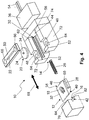
- Fig. 4 shows a further, third embodiment of a device 10, wherein additionally an electromagnet 36 is provided.
- the locking member 12 in the in Fig. 4 illustrated embodiment made of a magnetic metal or has at least one magnetic metal, so that the locking member 12 can be magnetically attracted by the electromagnet 36.
- the other components shown are in accordance with the in Fig. 3 illustrated embodiment formed and interconnected.
- a displacement of the Verrieglungsteils 12 done the different widths (in particular first width W 1 , second width W 2 ), in how far the locking member 12 protrudes from the receptacle 14, due to the position of the lower end of the guide element 20th in the heart curve 18, are variable by the electric motor.
- the electromagnet 36 has connecting lines 54, which serve to control or power supply of the electromagnet 36.
- Fig. 5 shows a further, fourth embodiment, wherein instead of a guide member 20 according to Fig. 3 , which consists of a disc or a plate 24 and a concentric pin 34, a pin-shaped guide member 20 is attached to a bracket 38 which abuts with its leg 78 on the rear wall 76 of the rear part 74. Tilting (for example, by a slight inclination of the guide member 20) is excluded due to the bracket 38 and the abutment of the leg 78 on the rear wall 76. Therefore, a guide plate 50 can be dispensed with, but with the in Fig. 5 As shown embodiment, a guide plate 50 may be additionally provided.
- the in the Fig. 1 to 5 shown embodiments have the advantage that they require relatively little space and specify a few components reliable and durable device 10 for moving a component 70 in the open and closed state.
- the slope 40 and the slope 42 may be formed according to the use of the device 10. Therefore, the slope 40 may have a much steeper or shallower angle (corresponding to the corresponding slope 42) than in FIGS Fig. 1 to 5 shown.
- an embodiment of a "push-push" mechanism with a device 10 (FIG. Fig. 1 to 5 ) has the advantage that no hooks are used, which must be introduced into a heart curve or engage behind a cutout or a recess. In the technical teaching disclosed here, only the locking member 12 is spent with relatively short strokes in the receptacle 14 or moved out of this.
- the bevels 52 of the side parts 72 are not relevant for the pivoting of the component 70. Therefore, the side parts 72 may also have a straight end. Furthermore, the receptacle 14, unlike in the Fig. 1 to 5 shown, instead of two side parts 72 and a rear part 74 integrally formed.
Description
Die vorliegende Erfindung betrifft eine Einrichtung, aufweisend einen Mechanismus zum Verbringen einer Komponente aus einem geöffneten in einen geschlossen Zustand und umgekehrt durch Drücken auf die Komponente. Ein derartiger Mechanismus ist auch als "Push-Push"-Mechanismus bekannt.The present invention relates to a device comprising a mechanism for moving a component from an open to a closed state and vice versa by pressing on the component. Such a mechanism is also known as a "push-push" mechanism.
Ein "Push-Push"-Mechanismus wird bei Komponenten verwendet, welche durch Drücken auf die Komponente beispielsweise ein Fach öffnen oder schließen sollen. Ein "Push-Push"-Mechanismus wird in der Regel mit einem Haken realisiert, wobei der Haken entlang einer Führung eine Ausnehmung hintergreift und damit das Fach verschließt oder sich herausbewegt und damit das Fach freigibt.A "push-push" mechanism is used with components that are designed to open or close a tray, for example, by pressing on the component. A "push-push" mechanism is usually realized with a hook, the hook along a guide engages behind a recess and thus closes the tray or moves out and thus releases the tray.
Aus
Bei den aus dem Stand der Technik bekannten Einrichtungen mit einem "Push-Push"-Mechanismus wird ein Arretierelement, welches an einem ersten Bauteil angeordnet ist, in einer Herzkurve geführt, welche an einem zweiten Bauteil angeordnet ist. Das Arretierelement entspricht daher im Wesentlichen einem Haken, der eine Ausnehmung hintergreift, um zumindest das erste oder zweite Bauteil in der verschlossenen Stellung zu halten.In the devices known from the prior art with a "push-push" mechanism, a locking element, which is arranged on a first component, guided in a heart curve, which is arranged on a second component. The locking element therefore essentially corresponds to a hook, which engages behind a recess in order to keep at least the first or second component in the closed position.
Diese aus dem Stand der Technik bekannten Arten des Aufbaus eines "Push-Push"-Mechanismus weisen Nachteile in Bezug auf den Aufbau, den benötigten Bauraum und die Anfälligkeit für Beschädigungen auf. Arretierelemente sowie Haken können leicht bei mehrmaligem Betätigen brechen. Ferner muss ein ausreichender Bauraum für den Haken oder das Arretierelement bei einem "Push-Push"-Mechanismus bereitgestellt werden, was sich ebenso nachteilig in Bezug auf die Kosten hierfür auswirkt.These known from the prior art types of construction of a "push-push" mechanism have disadvantages in terms of structure, the required installation space and susceptibility to damage. Locking elements and hooks can break easily when pressed several times. Furthermore, a sufficient space for the hook or the locking element in a "push-push" mechanism must be provided, which also has a disadvantageous effect on the cost of this.
Aufgabe der vorliegenden Erfindung ist es daher, eine Einrichtung mit einem Mechanismus zum Verbringen einer Komponente aus einem geöffneten in einen geschlossenen Zustand und umgekehrt anzugeben, wobei die Einrichtung einen geringen Bauraum benötigt und zuverlässig ein Verriegeln und Entriegeln bereitstellt.The object of the present invention is therefore to provide a device with a mechanism for moving a component from an open to a closed state and vice versa, wherein the device requires a small space and reliable locking and unlocking provides.
Erfindungsgemäß wird die Aufgabe durch eine Einrichtung mit den in Anspruch 1 angegebenen technischen Merkmalen gelöst.According to the invention the object is achieved by a device having the features specified in
Vorteilhafte Weiterbildungen der Erfindung sind in den Unteransprüchen im Detail angegeben.Advantageous developments of the invention are specified in the dependent claims in detail.
Bei einer Einrichtung, aufweisend einen Mechanismus zum Verbringen einer Komponente aus einem geöffneten in einen geschlossenen Zustand und umgekehrt durch Drücken auf die Komponente, sind eine Aufnahme, eine Komponentenaufnahme und ein Verriegelungsteil vorgesehen, welches
in der Aufnahme verschieblich gelagert und in einem geöffneten Zustand der Komponente um eine erste Weite aus der Aufnahme hervorsteht und in einem geschlossenen Zustand um eine zweite Weite aus der Aufnahme hervorsteht und in der Komponentenaufnahme aufgenommen ist, wobei die zweite Weite größer ist als die erste Weite, wobei das Verriegelungsteil gegen die Kraft einer Federeinrichtung in der Aufnahme aufgenommen ist und das Verriegelungsteil eine Herzkurve aufweist, in welcher ein Führungselement verschieblich gelagert ist, welches quer zu der Verschieberichtung des Verriegelungsteils verlagerbar ist, und wobei das Verriegelungsteil an der der Aufnahme abgewandten Seite eine Schräge und die Komponentenaufnahme eine korrespondierende Schräge aufweisen, welche im geschlossenen Zustand der Komponente aneinander anliegen und zueinander verschieblich sind, wobei eine erste Kante der Komponentenaufnahme versetzt zu einer zweiten Kante der Komponentenaufnahme verläuft.In a device comprising a mechanism for moving a component from an open to a closed state and vice versa by pressing on the component, a receptacle, a component receptacle and a locking part are provided which
slidably mounted in the receptacle and protrudes in an open state of the component by a first width of the receptacle and protrudes in a closed state by a second width of the receptacle and is received in the component receptacle, wherein the second width is greater than the first width wherein the locking member is received against the force of a spring means in the receptacle and the locking member has a heart cam in which a guide member is slidably mounted, which is transversely displaceable to the direction of displacement of the locking part, and wherein the locking member on the side facing away from the receptacle Slant and the component holder have a corresponding slope, which abut each other in the closed state of the component and are mutually displaceable, wherein a first edge of the component holder is offset from a second edge of the component holder.
Die Einrichtung weist gegenüber bekannten "Push-Push"-Mechanismen den Vorteil auf, dass sie nur einen geringen Bauraum benötigt. Im Gegensatz zu bekannten Einrichtungen ist an der Komponente, welche verschwenkt oder anderweitig geöffnet wird, kein ab- oder vorstehendes Teil angeordnet, welches in eine Verriegelungseinrichtung eingreift. Die Komponente weist lediglich eine Komponentenaufnahme auf, welche eine Schräge besitzt. Die Komponentenaufnahme weist eine erste Kante und eine zweite Kante auf, von welchen sich die Komponentenaufnahme in die Komponente hinein erstreckt. Hierbei verlaufen die erste Kante und die zweite Kante versetzt zueinander, so dass das Verriegelungsteil im geschlossenen Zustand der Komponente bei einem Druck auf die Komponente über die erste Kante, die weiter in Richtung des Verriegelungsteils hervorsteht als die zweite Kante, in die Aufnahme verbracht wird, wobei das Verriegelungsteil über die Herzkurve in einer Position gehalten wird, in der das Verriegelungsteil um eine erste Weite aus der Aufnahme hervorsteht. Danach kann die Komponente geöffnet werden, da das Verriegelungsteil nur um die erste Weite aus der Aufnahme hervorsteht, welche eine Verlagerung der Komponente ermöglicht, da das Verriegelungsteil in dieser Position nicht in Anlage mit der zweiten Kante kommt, die weniger weit in Richtung des Verriegelungsteils aus der Aufnahme hervorsteht als die erste Kante. Um die Komponente zu verschließen, wird die Komponente in Richtung des Verriegelungsteils bewegt. Die zweite Kante der Komponente passiert das Verriegelungsteil, ohne das Verriegelungsteil zu berühren, da das Verriegelungsteil nur um die erste Weite aus der Aufnahme hervorsteht und die zweite Kante einen größeren Abstand zu der Aufnahme und dem Verriegelungsteil aufweist als die erste Kante. Die erste Kante drückt beim Passieren des Verriegelungsteils das Verriegelungsteil weiter in die Aufnahme hinein, wobei über die Herzkurve das Verriegelungsteil entriegelt wird und über die Federeinrichtung aus der Aufnahme herausbewegt wird. Nachdem die erste Kante das Verriegelungsteil passiert hat, wird kein Druck mehr auf die Komponente ausgeübt, so dass das Verriegelungsteil in die Komponentenaufnahme bewegt wird und die Komponente verriegelt.The device has the advantage over known "push-push" mechanisms that it only requires a small amount of space. In contrast to known devices, no ab- or projecting part is arranged on the component, which is pivoted or otherwise opened, which engages in a locking device. The component has only one component receptacle, which has a bevel. The component receptacle has a first edge and a second edge, from which the component receptacle extends into the component. In this case, the first edge and the second edge are offset relative to one another, so that the locking part is brought into the receptacle in the closed state of the component with a pressure on the component over the first edge, which protrudes further in the direction of the locking part than the second edge, wherein the locking member is held over the heart cam in a position in which the locking member protrudes a first distance from the recording. Thereafter, the component can be opened because the locking member protrudes only by the first width of the receptacle, which allows a displacement of the component, since the locking member does not come into contact with the second edge in this position, the less far in the direction of the locking part the receptacle protrudes as the first edge. To close the component, the component is moved in the direction of the locking part. The second edge of the component passes through the locking member without contacting the locking member because the locking member protrudes only about the first width of the receptacle and the second edge has a greater distance from the receptacle and the locking member than the first edge. The first edge presses on passing the locking member, the locking member further into the receptacle, wherein on the heart cam, the locking member is unlocked and is moved over the spring means of the receptacle. After the first edge has passed the locking member, no pressure is exerted on the component, so that the locking member is moved into the component holder and locks the component.
Das Verriegelungsteil, welches eine korrespondierende Schräge zur Schräge der Komponentenaufnahme aufweist, wird zum Verbringen in den geöffneten Zustand der Komponente in die Aufnahme geschoben und zum Verriegeln der Komponente greift das Verriegelungsteil in die Komponentenaufnahme, wobei die beiden Schrägen aneinander anliegen. Wird im geschlossenen Zustand der Komponente ein Druck auf die Komponente, im Wesentlichen im Bereich der Komponentenaufnahme, ausgeübt, so gleitet das Verriegelungsteil entlang der Schräge der Komponentenaufnahme in die Aufnahme hinein, bis die Komponente von dem Verriegelungsteil nicht mehr gehalten wird. Nachdem die Komponente in den geöffneten Zustand verbracht worden ist, steht das Verriegelungsteil um eine erste Weite aus der Aufnahme hervor. Während des Verbringens der Komponente in den geöffneten Zustand gibt es zumindest einen Zustand, in welchem das Verriegelungsteil fast vollständig in der Aufnahme aufgenommen ist. Nachdem sich die Komponentenaufnahme und die Komponente nicht mehr im Bereich des Verriegelungsteils befinden, erfolgt durch die Federeinrichtung eine Bewegung des Verriegelungsteils mindestens so weit, dass dieses um ein bestimmtes Maß aus der Aufnahme hervorsteht. Die Weiten, um welche das Verriegelungsteil aus der Aufnahme hervorsteht, werden durch das Führungselement und die Herzkurve festgelegt. Die Herzkurve weist dazu Bereiche auf, in welchen das Führungselement in verschiedenen Stellungen gehalten werden kann. Dadurch wird die Position des Verriegelungsteils festgelegt. Beim Schließen der Komponente wird die Komponente wieder in Richtung des Verriegelungsteils bewegt. Hierbei passiert die Komponente das Verriegelungsteil, bis die erste Kante das Verriegelungsteil in die Aufnahme drückt, das Verriegelungsteil entriegelt wird und das Verriegelungsteil über die Federeinrichtung aus der Aufnahme in die Komponentenaufnahme gedrückt wird. Anschließend wird die Komponente in diesem verriegelten Zustand durch das Verriegelungsteil gehalten. Wird erneut ein Druck auf die Komponente ausgeübt, so wird das Verriegelungsteil in die Aufnahme geschoben und die Komponente freigegeben.The locking member, which has a corresponding slope to the slope of the component receiving, is pushed to spend in the open state of the component in the receptacle and for locking the component engages the locking member in the component receptacle, wherein the two slopes abut each other. If, in the closed state of the component, pressure is exerted on the component, essentially in the area of the component receptacle, then the locking part slides along the slope of the component receptacle into the receptacle until the component is no longer held by the locking part. After the component has been moved to the open state, stands the locking member by a first distance from the recording forth. During the placement of the component in the open state, there is at least one state in which the locking part is almost completely received in the receptacle. After the component holder and the component are no longer in the region of the locking part, the spring device causes the locking part to move at least so far that it protrudes from the receptacle by a certain amount. The widths by which the locking part protrudes from the receptacle are determined by the guide element and the heart curve. The heart curve has areas in which the guide element can be held in different positions. This determines the position of the locking part. When closing the component, the component is moved back in the direction of the locking part. Here, the component passes through the locking member until the first edge presses the locking member into the receptacle, the locking member is unlocked and the locking member is pressed via the spring means from the receptacle in the component holder. Subsequently, the component is held in this locked state by the locking member. If a pressure is exerted on the component again, then the locking part is pushed into the receptacle and released the component.
Um eine derartige Bewegung sicherstellen zu können, ist bei der vorliegenden Erfindung nicht nur die Herzkurve, welche auf einer Oberseite in das Verriegelungsteil eingebracht ist, verschieblich, sondern auch das Führungselement. Die Schräge der Komponentenaufnahme und die Schräge des Verriegelungsteils sind so ausgebildet, dass die Schräge des Verriegelungsteils, insbesondere in Richtung der Komponente im geöffneten Zustand hin, abnimmt und die Schräge der Komponentenaufnahme in Richtung des Verriegelungsteils entsprechend der Ausgestaltung der Schräge des Verriegelungsteils zunimmt.In order to be able to ensure such a movement, in the present invention, not only the heart curve, which is introduced on an upper side in the locking part, displaceable, but also the guide element. The slope of the component receptacle and the slope of the locking member are formed so that the slope of the locking member, in particular in the direction of the component in the open state, decreases, and the slope of the component receptacle in the direction of Locking part increases according to the configuration of the slope of the locking part.
Die Einrichtung kann ferner eine quer zu der Verschieberichtung des Verriegelungsteils verlaufende Führung aufweisen, in welcher das Führungselement verschiebbar ist. Die Führung stellt sicher, dass das Führungselement bei der Verlagerung quer zu der Verschieberichtung des Verriegelungsteils nicht verkantet und die Einrichtung blockiert.The device may further comprise a transverse to the direction of displacement of the locking member extending guide, in which the guide element is displaceable. The guide ensures that the guide element does not tilt when displaced transversely to the direction of displacement of the locking part and blocks the device.
Das quer zu der Verschieberichtung des Verriegelungsteils verschiebbare Führungselement erlaubt eine Ausgestaltung der Einrichtung, wobei das Verriegelungsteil nur entlang einer Verschieberichtung bewegt wird und die Seiten des Verriegelungsteils an den Seitenwänden, welche die Aufnahme begrenzen und definieren, anliegen.The displaceable transversely to the direction of displacement of the locking member guide member allows an embodiment of the device, wherein the locking member is moved only along a direction of displacement and abut the sides of the locking member on the side walls which define and define the recording.
Die Federeinrichtung kann mindestens eine Druckfeder aufweisen. Jedoch können im Sinne der Erfindung auch andere Federeinrichtungen verwendet werden, welche bestrebt sind, das Verriegelungsteil aus der Aufnahme zu drücken.The spring device may have at least one compression spring. However, other spring means can be used in the context of the invention, which endeavor to push the locking member from the receptacle.
In weiterer alternativer Ausgestaltung weist die Federeinrichtung mindestens zwei Dauermagnete auf, wobei ein Dauermagnet in der Aufnahme und der andere Dauermagnet an dem Verriegelungsteil angeordnet und die Dauermagnete so zueinander ausgerichtet sind, dass sie sich abstoßen. Eine derartige Ausführung umfasst daher zwei Dauermagnete, welche die Aufgabe der Federeinrichtung übernehmen.In a further alternative embodiment, the spring device has at least two permanent magnets, wherein a permanent magnet in the receptacle and the other permanent magnet disposed on the locking member and the permanent magnets are aligned with each other so that they repel each other. Such an embodiment therefore comprises two permanent magnets, which take over the task of the spring device.
Die Einrichtung kann in weiteren Ausführungsformen einen Elektromagneten aufweisen, wobei das Verriegelungsteil aus einem magnetischen Metall besteht und das Verriegelungsteil durch den Elektromagneten in die Aufnahme bewegbar ist, wenn der Elektromagnet aktiviert ist. Bei dieser Ausführung kann ein Öffnen und Schließen der Komponente bzw. ein Verbringen der Komponente in den geöffneten und geschlossenen Zustand elektrisch erfolgen. So kann ein Bedienelement betätigt oder eine andere Steuereinrichtung bedient werden, welche eine Verlagerung des Verriegelungsteils aufgrund des Elektromagneten gegen die Kraft einer Feder (Federeinrichtung) bewirken. Diese Ausgestaltungen bieten ferner den Vorteil, dass selbst bei einem Ausfall der Steuereinrichtungen oder der Stromversorgung ein Öffnen und Schließen bzw. ein Verbringen in den geöffneten und geschlossenen Zustand der Komponente möglich sind, da durch Drücken auf die Komponente, insbesondere im Bereich der Komponentenaufnahme, das Verriegelungsteil in die Aufnahme verschiebbar ist (bei einem Verbringen im geöffneten Zustand; oder aus der Aufnahme heraus bewegbar, zum Verbringen in den geöffneten Zustand), da keine Kraft mehr durch den Elektromagneten wirkt und die Federeinrichtung eine derartige Bewegung bzw. Betätigung zulässt. Die Einrichtung kann somit auch als Sicherheitseinrichtung mit einem stromlos betreibbaren Mittel zum Öffnen und Schließen einer Vorrichtung Verwendung finden. Es ist aber auch möglich, eine Vorrichtung im geschlossenen Zustand über den Elektromagneten zu verriegeln, so dass die Vorrichtung nicht geöffnet werden kann.The device may in other embodiments comprise an electromagnet, wherein the locking part is made of a magnetic metal and the locking part is movable by the electromagnet into the receptacle when the electromagnet is activated. In this embodiment, an opening and closing of the component or a movement of the component in the open and closed state carried out electrically. Thus, an operating element can be actuated or another control device operated, which effect a displacement of the locking part due to the electromagnet against the force of a spring (spring device). These embodiments also offer the advantage that even in the event of a failure of the control devices or the power supply, opening and closing or movement into the open and closed state of the component are possible, since by pressing on the component, in particular in the area of the component receptacle Locking member is slidable (when moved in the open state, or out of the receptacle to move to the open state) slidably into the receptacle, since no force acts by the electromagnet and the spring device allows such a movement or actuation. The device can thus also be used as a safety device with a device for opening and closing a device which can be operated without current. But it is also possible to lock a device in the closed state on the electromagnet, so that the device can not be opened.
In weiteren Ausführungsformen ist das Führungselement ein Stift. Ein erstes Ende des Stiftes ist in der Herzkurve und das zweite Ende des Stiftes ist in der querverlaufenden Führung verschieblich gelagert.In further embodiments, the guide element is a pin. A first end of the pin is in the heart cam and the second end of the pin is slidably mounted in the transverse guide.
Alternativ kann das Führungselement jedoch auch als Kugel ausgebildet sein, wobei entsprechend der gewählten Ausführungsform die Führung und die Herkurve entsprechend ausgebildet sind. Ein Führungselement, welches als Kugel ausgebildet ist, weist gegenüber anderen Formen den Vorteil auf, dass die Reibung deutlich reduziert ist. Weiterhin ist es auch möglich, eine Herzkurve und ein entsprechendes Führungselement auf beiden Seiten des Verriegelungsteils vorzusehen. Sind in derartigen Ausführungen beide Führungselemente beispielsweise Metallkugeln und ist das Verriegelungsteil ebenfalls aus Metall gefertigt, ergeben sich Anwendungsgebiete für erfindungsgemäße Einrichtungen, welche bisher mit Systemen, welche eine Herzkurve umfassen, nicht realisiert werden konnten. Hierzu sind beispielsweise Türverschlüsse zu nennen. Derartige Systeme sind dabei sehr robust. Es können anstelle von Metallen für die Bestandteile der Einrichtung auch andere Werkstoffe verwendet werden.Alternatively, however, the guide element may also be formed as a ball, according to the selected embodiment, the guide and the Herkurve are formed accordingly. A guide element, which is designed as a ball, has the advantage over other forms that the friction is significantly reduced. Furthermore, it is also possible, a heart curve and a corresponding Provide guide element on both sides of the locking part. If, in such embodiments, both guide elements are, for example, metal balls and if the locking part is also made of metal, there are fields of application for devices according to the invention which hitherto could not be realized with systems comprising a heart curve. For this purpose, for example, door closures are mentioned. Such systems are very robust. Other materials may be used instead of metals for the constituents of the device.
Bei weiteren Ausführungsformen kann der Stift zwischen dem ersten Ende und dem zweiten Ende einen ihn umgebenden Teller aufweisen, der an einem Freiraum zwischen der Aufnahme und dem Verriegelungsteil verschieblich gelagert ist. Ein umgebender Teller liegt in diesen Ausführungsformen auf dem Verriegelungsteil auf, wobei das erste Ende des Stiftes in der Herzkurve aufgenommen ist. Bei einem Verlagern des Führungselementes, sowohl in Querrichtung entlang der Führung als auch in der Herzkurve, wird ein Blockieren oder Verkanten des Führungselementes verhindert, da der Teller ein Verkippen des Stiftes verhindert.In further embodiments, the pin between the first end and the second end may have a surrounding plate which is slidably mounted on a clearance between the receptacle and the locking member. A surrounding plate in these embodiments rests on the locking member with the first end of the pin received in the heart cam. In a displacement of the guide element, both in the transverse direction along the guide and in the heart curve, a blocking or tilting of the guide element is prevented because the plate prevents tilting of the pin.
Das Verriegelungsteil, das Führungselement und/oder die Aufnahme können aus einem Kunststoff und/oder Metall bestehen. Kunststoffteile lassen sich einfach in einem Spritzgussverfahren herstellen und reduzieren die Kosten zur Herstellung der Einrichtung sowie die Gesamtkosten für die Einrichtung. Metallteile sorgen für eine robuste Ausführung der Einrichtung.The locking member, the guide member and / or the receptacle may consist of a plastic and / or metal. Plastic parts are easy to produce by injection molding and reduce the cost of manufacturing the device and the overall cost of the device. Metal parts ensure a robust finish of the device.
Das Verriegelungsteil kann an mindestens einer Seite Führungsmittel aufweisen, über welche das Verriegelungsteil an mindestens einem korrespondierenden Führungsmittel der Aufnahme verschiebbar ist. Über die Führungsmittel wird ein Verkanten des Verriegelungsteils verhindert. Die Führungsmittel können zudem mit einem reibungsreduzierenden Material oberflächenbeschichtet oder so ausgebildet sein, dass die Oberfläche der Führungsmittel reibungsreduzierend ist (bspw. Struktur).The locking part may comprise on at least one side guide means, via which the locking part is displaceable on at least one corresponding guide means of the receptacle. About the guide means will prevents tilting of the locking part. The guide means may also be surface coated with a friction reducing material or formed so that the surface of the guide means is friction reducing (eg structure).
Insbesondere kann die Schräge des Verriegelungsteils gegenüber einer Verschiebeebene einen Winkel von 15° bis 50° (insbesondere im Bereich von 45°) aufweisen.In particular, the slope of the locking part with respect to a displacement plane at an angle of 15 ° to 50 ° (in particular in the range of 45 °).
Der Winkel ist jedoch abhängig von der zweiten Weite des Abschnitts des Verriegelungsteils, welcher im geschlossenen Zustand der Komponente aus der Aufnahme hervorsteht, und von weiteren Maßen der Einrichtung, sowie den Maßen der Komponente. Es können auch wesentlich steilere Winkel vorgesehen sein, wobei dann der Bereich des Verriegelungsteils, welcher im geschlossenen Zustand der Komponente aus der Aufnahme hervorsteht, eine geringere Größe aufweist.However, the angle is dependent on the second width of the portion of the locking part, which protrudes from the receptacle in the closed state of the component, and of further dimensions of the device, as well as the dimensions of the component. It can also be provided significantly steeper angle, in which case the region of the locking part, which protrudes from the receptacle in the closed state of the component, has a smaller size.
Das Führungselement kann ferner mit einem Bügel verbunden sein, welcher entlang und quer zu einem die Aufnahme begrenzenden Rückteil verlagerbar ist.The guide element may also be connected to a bracket, which is displaceable along and transversely to a rear part bounding the receptacle.
Weiterbildungen der Erfindung sowie Ausgestaltungsmöglichkeiten ergeben sich aus der nachfolgenden Figurenbeschreibung. Die in den Figuren gezeigten Ausführungsbeispiele weisen beispielhaften Charakter auf und sind daher nicht einschränkend zu verstehen und können bei zu implementierenden Ausführungsformen vom Veranschaulichten abweichen.Further developments of the invention and design options will become apparent from the following description of the figures. The embodiments shown in the figures have exemplary character and are therefore not limiting and may differ from the illustrated embodiments to be implemented.
In den Zeichnungen zeigen:
- Fig. 1
- eine perspektivische Ansicht einer Einrichtung mit einem "Push-Push"-Mechanismus in schematischer Darstellung;
- Fig. 2a - 2k
- eine schematische Darstellung der Verlagerung zum Verbringen einer Einrichtung mit einem "Push-Push"-Mechanismus;
- Fig. 3
- eine Explosionszeichnung einer zweiten Ausführungsform einer Einrichtung mit einem "Push-Push"-Mechanismus;
- Fig. 4
- eine dritte Ausführungsform einer Einrichtung mit einem "Push-Push"-Mechanismus; und
- Fig. 5
- eine vierte Ausführungsform einer Einrichtung mit einem "Push-Push"-Mechanismus.
- Fig. 1
- a perspective view of a device with a "push-push" mechanism in a schematic representation;
- Fig. 2a - 2k
- a schematic representation of the displacement for bringing a device with a "push-push"mechanism;
- Fig. 3
- an exploded view of a second embodiment of a device with a "push-push"mechanism;
- Fig. 4
- a third embodiment of a device with a "push-push"mechanism; and
- Fig. 5
- a fourth embodiment of a device with a "push-push" mechanism.
In den Figuren entsprechen mit den gleichen Bezugszeichen versehene Teile im Wesentlichen einander, solange nichts anderes angegeben ist. Ferner wird im Folgenden darauf verzichtet, Bestandteile anzugeben und zu beschreiben, welche nicht wesentlich für das Verständnis der hier offenbarten technischen Lehre sind.In the figures, parts provided with the same reference numerals substantially correspond to each other unless otherwise specified. Furthermore, it will be omitted below to specify and describe components which are not essential to the understanding of the technical teaching disclosed herein.
Eine Klappe 80 weist eine Komponente 70 auf, wobei die Komponente 70 integraler Bestandteil der Klappe 80 ist. Die Komponente 70 weist eine Komponentenaufnahme 16 auf. Die Komponentenaufnahme 16 erstreckt sich über die Komponente 70 hinaus bis zu einer ersten Kante 82. Ferner erstreckt sich die Komponentenaufnahme 16 bis zu einer zweiten Kante 84. Die erste Kante 82 verläuft versetzt zu der zweiten Kante 84. Die erste Kante 82 weist einen Abstand d zu der zweiten Kante 84 auf.A
Die Klappe 80 ist um eine nicht dargestellte Achse verschwenkbar. Diese Achse befindet sich links von der Komponente 70. In der Komponentenaufnahme 16 ist ein Verriegelungsteil 12 aufgenommen. Das Verriegelungsteil 12 ist in einer Aufnahme 14 gelagert. Die Aufnahme 14 weist Führungen 30 auf. Das Verriegelungsteil 12 weist Führungsleisten 28 auf, die in den Führungen 30 aufgenommen sind. Über die Führungsleisten 28 ist das Verriegelungsteil in der Aufnahme 14 verschieblich geführt.The
Die Komponentenaufnahme 16 weist eine Schräge 42 und das Verriegelungsteil 12 eine korrespondierende Schräge 40 auf. An der der Schräge 40 gegenüberliegenden Rückwand weist das Verriegelungsteil 12 zwei Öffnungen 86 auf, in welchen Federn (in
Wird von unten Druck auf die Klappe 80 ausgeübt, wird das Verriegelungsteil 12 gegen die Kraft der Federn in die Aufnahme 14 geschoben. Hierbei wird der Stift 92 (siehe
Soll die Klappe 80 wieder geschlossen und verriegelt werden, so wird die Klappe 80 von unten gegen das Verriegelungsteil 12 gedrückt, wobei die zweite Kante 84 das Verriegelungsteil 12 ohne Kontakt zu diesem passiert. Wird die Klappe 80 weiter nach oben gedrückt, passiert die erste Kante 82 das Verriegelungsteil 12 und drückt das Verriegelungsteil 12 in die Aufnahme 14, da das Verriegelungsteil um die erste Weite W1 aus der Aufnahme 14 hervorsteht. Der Stift 92 wird dabei aus seiner Anlageposition verbracht und gibt eine Verlagerung des Verriegelungsteils 12 frei, wobei das Verriegelungsteil 12 durch die Federn aus der Aufnahme 14 gedrückt wird und in die Komponentenaufnahme 16 gelangt. Danach ist die Klappe 80 wieder durch die Einrichtung 10 verriegelt und kann durch erneutes Drücken von unten entriegelt werden.If the
Die
In den
Das Verriegelungsteil 12 ist ferner über Führungsmittel in der Aufnahme 14 verschieblich gelagert. Die Aufnahme 14 ist in den
Das Verriegelungsteil 12 weist an seiner Oberseite 32 (siehe
Über der Aufnahme 14 kann eine Abdeckung angeordnet sein, welche ein Verschwenken der Komponente 70 nach oben in Richtung der Pfeile 88 begrenzt.A cover can be arranged above the
In den
In
Um die Komponente 70 von dem geschlossenen Zustand aus
Wird auf die Komponente 70 weiter Druck in Richtung des Pfeils 88 ausgeübt, wie in
Anschließend wird der Druck auf die Komponente 70 aufgegeben, wobei sich das Verriegelungsteil 12 durch die Feder in Richtung des Pfeils 94 nach links bewegt (
In
Um die Komponente 70 wieder in den geschlossenen Zustand zu verbringen, wird die Komponente 70 in Richtung des Pfeils 88 nach oben bewegt.
Wird der Druck auf die Komponente 70 in Richtung des Pfeils 88 weiter aufrecht erhalten, kommt die erste Kante 82 der Komponentenaufnahme 16 in Kontakt mit dem Verriegelungsteil 12, wobei durch den Druck das Verriegelungsteil 12 gegen die Kraft der Feder in Richtung des Pfeils 90 in die Aufnahme 14 geschoben wird (
In
Anschließend wird kein Druck mehr in Richtung des Pfeils 88 auf die Komponente 70 aufgebracht. Die Komponente 70 bewegt sich dann in Richtung des Pfeils 96 nach unten und das Verriegelungsteil 12 wird durch die Feder in Richtung des Pfeils 94 aus der Aufnahme 14 gedrückt (
Das Verriegelungsteil 12 wird durch die Feder weiter in Richtung des Pfeils 94 aus der Aufnahme 14 herausgeschoben, wobei das Verriegelungsteil 12 hierbei in die Komponentenaufnahme 16 bewegt wird (
In
Die Komponentenaufnahme 16 ist in einer schematisch angedeuteten Komponente 70 eingebracht. Die Seitenteile 72 weisen jeweils innenliegend auf den Seiten 62, welche die Aufnahme 14 begrenzen, eine Führung 30 auf. Die Führung 30 ist jeweils so ausgebildet, dass in der Führung 30 aufgenommene Führungsleisten 28 des Verriegelungsteils 12 verschoben werden können, jedoch das Verriegelungsteil 12 nicht vollständig aus der Aufnahme 14 im zusammengebauten Zustand herausbewegt werden kann. Die Rückwand 56 des Rückteils 74 weist eine Öffnung 44 auf, in welcher teilweise eine Feder 26 aufgenommen ist. Das gegenüberliegende Ende der Feder 26 ist auf einen Zapfen 46 aufgeschoben. Der Zapfen 46 befindet sich auf der Rückseite 58 des Verriegelungsteils 12. Die Führungsleisten 28 (in
Die Seitenteile 72 weisen ferner Ausbuchtungen 48 auf, in welchen Öffnungen 64 eingebracht sind. In die Ausnehmungen 48 wird eine Führungsplatte 50 so eingesetzt, dass die Öffnungen 64 der Ausnehmungen 48 mit Öffnungen 66 einer Führungsplatte 50 fluchten. Über die Öffnungen 64 und 66 kann die Führungsplatte 50 beispielsweise mittels Schrauben oder Bolzen mit den Seitenteilen 72 verbunden werden. Bevor jedoch die Führungsplatte 50 mit den Seitenteilen 72 verbunden wird, wird ein Führungselement 20 so auf das Verriegelungsteil 12 aufgesetzt, dass ein unteres stiftförmiges Ende in die auf der Oberfläche 32 des Verriegelungsteils 12 eingebrachte Herzkurve 18 eingreift. Der das Führungselement 20 umgebende Teller 24 liegt mit seiner unteren Fläche auf der Oberfläche 32 des Verriegelungsteils 12 auf. Das obere Ende 34 des in diesem Abschnitt stiftförmig ausgebildeten Führungselementes 20 ist innerhalb einer Führung 22 der Führungsplatte 50 verschieblich gelagert.The
Das Verriegelungsteil 12 weist am vorderen Ende eine Schräge 40 auf, welche korrespondierend zu einer Schräge 42 der Komponentenaufnahme 16 der Komponente 70 ausgebildet ist. Im geschlossenen Zustand der Komponente 70 befindet sich das Verriegelungsteil 12 in der Komponentenaufnahme 16, wobei die Schräge 40 an der Schräge 42 anliegt.The locking
In diesem Zustand (siehe
Zum Öffnen der Komponente 70 bzw. zum Verbringen in den geöffneten Zustand wird im Wesentlichen im Bereich der Komponentenaufnahme 16 von unten auf die Komponente 70 gedrückt, wobei aufgrund der Schräge 42 der Komponentenaufnahme 16 und der Schräge 40 des Verriegelungsteils 12 eine Verlagerung des Verriegelungsteils 12 entlang der Führung 30 in Richtung der Rückwand 56 innerhalb der Aufnahme 14 erfolgt (siehe Verschieberichtung 68;
Hierbei erfolgt zugleich eine Verlagerung des Führungselementes 20 entlang der Führung 22, wobei aufgrund der Herzkurve 18 das untere Ende des Führungselementes 20 gegenüber seinem Ausgangszustand in den entgegengesetzten Bereich der Herzkurve 18 verlagert wird. Bei der in
Ist die Komponente 70 in den geöffneten Zustand verbracht worden, wobei diese nach unten verschwenkt ist (in
Wird nun die Komponente 70 wieder in den geschlossenen Zustand verbracht, so wird die Komponente 70 im Wesentlichen von unten gegen das Verriegelungsteil 12 gedrückt, wobei die zweite Kante 84 das Verriegelungsteil 12 passiert (
Bei einer Verlagerung der Komponente 70 nach unten bewegt sich die vordere Kante des Verriegelungsteils 12 in die Komponentenaufnahme 16 hinein, bis die vordere Kante des Verriegelungsteils 12 durch die Feder 26 automatisch in die Komponentenaufnahme 16 vollständig gedrückt worden ist. Durch das Verlagern des Verriegelungsteils 12 in die Komponentenaufnahme 16 wird das untere Ende des Führungselementes 20 über die mit Blick auf
Soll die Komponente 70 nun wieder aus dem geschlossenen in den geöffneten Zustand verbracht werden, so reicht ein leichtes Drücken von unten auf die Komponente 70 im Bereich der Komponentenaufnahme 16, so dass sich der oben beschriebene Vorgang wiederholt.If the
Die anderen dargestellten Bestandteile sind entsprechend der in
Bei der in
Die in den
Die Schrägen 52 der Seitenteile 72 sind für das Verschwenken der Komponente 70 nicht maßgeblich. Daher können die Seitenteile 72 auch einen geraden Abschluss aufweisen. Ferner kann die Aufnahme 14, anders als in den
Claims (12)
- Device (10) comprising a mechanism for bringing a component from an open state to a closed state and conversely by pressing on the component, wherein the device comprises a receptacle (14), a component receiver (16) and a locking part (12), which is displaceably mounted in the receptacle (14) and in an open state of the component protrudes by a first width (W1) from the receptacle (14) and in a closed state protrudes by a second width (W2) from the receptacle (14) and is received in the component receiver (16), wherein the second width (W2) is greater than the first width (W1), wherein the locking part (12) is mounted in the receptacle (14) against the force of a spring device and the locking part (12) has a heart cam (18) in which a guide element (20) is displaceably mounted, the guide element being displaceable transversely to the displacement direction (68) of the locking part (12), and wherein the locking part (12) has a chamfer (40) at the side remote from the receptacle (14) and the component receiver (16) has a corresponding chamfer (42), which chamfers in the closed state of the component bear against and are displaceable relative to one another, wherein a first edge (82) of the component receiver (16) extends at an offset with respect to a second edge (84) of the component receiver (16).
- Device (10) according to claim 1, comprising a guide (22) which extends transversely to the displacement direction (68) of the locking part (12) and in which the guide element (20) is displaceable.
- Device (10) according to claim 1 or 2, wherein the spring device comprises at least one compression spring.
- Device (10) according to claim 1 or 2, wherein the spring device comprises at least two permanent magnets, wherein one permanent magnet is arranged in the receptacle (14) and the other permanent magnet is arranged at the locking part (12) and the permanent magnets are so oriented relative to one another that they mutually repel.
- Device (10) according to any one of claims 1 to 3, comprising an electromagnet (36), wherein the locking part (12) consists of a magnetic metal and the locking part (12) is movable by the electromagnet (36) into the receptacle (14) when the electromagnet (36) is activated.
- Device (10) according to any one of claims 1 to 5, wherein the guide element (20) is a pin (92) and a first end of the pin (92) is displaceably mounted in the heart cam (18) and the second end (34) of the pin (92) is displaceably mounted in the transversely extending guide (22).
- Device (10) according to any one of claims 1 to 5, wherein the guide element is a ball.
- Device (10) according to claim 6, wherein the pin has between the first end and the second end (34) a plate (24) which surrounds it and which is displaceably mounted in a free space between the receptacle (14) and the locking part (12).
- Device (10) according to any one of claims 1 to 8, wherein the locking part (12), the guide element (20) and/or the receptacle (14) consists or consist of plastics and/or metal.
- Device (10) according to any one of claims 1 to 9, wherein the locking part (12) has at at least one side (60) guide means (28) by way of which the locking part (12) is displaceable at at least one corresponding guide means (30) of the receptacle (14).
- Device (10) according to any one of claims 1 to 10, wherein the chamfer (40) of the locking part (12) has an angle of 15° to 50° relative to a displacement plane.
- Device (10) according to any one of claims 1 to 5 and 9 to 11, wherein the guide element (20) is connected with a bracket (38) which is displaceable along and transversely to a back part (74) bounding the receptacle (14).
Applications Claiming Priority (2)
| Application Number | Priority Date | Filing Date | Title |
|---|---|---|---|
| DE102013108794 | 2013-08-14 | ||
| PCT/EP2014/063160 WO2015022106A1 (en) | 2013-08-14 | 2014-06-23 | Device having a push-push mechanism |
Publications (2)
| Publication Number | Publication Date |
|---|---|
| EP3033464A1 EP3033464A1 (en) | 2016-06-22 |
| EP3033464B1 true EP3033464B1 (en) | 2019-01-02 |
Family
ID=51022846
Family Applications (1)
| Application Number | Title | Priority Date | Filing Date |
|---|---|---|---|
| EP14733594.7A Active EP3033464B1 (en) | 2013-08-14 | 2014-06-23 | Device with push-push mechanism |
Country Status (3)
| Country | Link |
|---|---|
| EP (1) | EP3033464B1 (en) |
| CN (1) | CN105556046B (en) |
| WO (1) | WO2015022106A1 (en) |
Families Citing this family (4)
| Publication number | Priority date | Publication date | Assignee | Title |
|---|---|---|---|---|
| CN106049937B (en) * | 2016-07-25 | 2019-01-29 | 曾庆义 | With safety lock without anti-collision multi-layer parking device |
| DE102017104476B4 (en) | 2017-03-03 | 2023-06-15 | Lisa Dräxlmaier GmbH | INTERIOR ARRANGEMENT FOR A MOTOR VEHICLE |
| CN109209084B (en) * | 2017-07-06 | 2024-01-16 | 杭州神林电子有限公司 | Door closure locking device for household appliances |
| DE102018120620A1 (en) * | 2018-08-23 | 2020-02-27 | Emka Beschlagteile Gmbh & Co. Kg | Locking device for a door |
Family Cites Families (8)
| Publication number | Priority date | Publication date | Assignee | Title |
|---|---|---|---|---|
| FR1588802A (en) * | 1968-04-26 | 1970-03-16 | ||
| DE10211124A1 (en) * | 2002-03-14 | 2003-09-25 | Hella Kg Hueck & Co | Vanity mirror lamp unit for fitting in vehicle roof, pivoted without aid of spring actuating system |
| KR100633137B1 (en) * | 2005-08-26 | 2006-10-12 | 현대모비스 주식회사 | Device for latching a tray |
| JP4906706B2 (en) * | 2007-12-26 | 2012-03-28 | 株式会社ニフコ | Safety device and opening / closing mechanism |
| CN102197185B (en) * | 2008-10-29 | 2014-03-26 | 株式会社利富高 | Latch device |
| JP5295074B2 (en) * | 2009-11-02 | 2013-09-18 | 株式会社ニフコ | Lock device and door using the same |
| JP5789438B2 (en) * | 2011-07-13 | 2015-10-07 | 株式会社ニフコ | Latch device |
| WO2013022907A1 (en) * | 2011-08-09 | 2013-02-14 | Illinois Tool Works Inc. | Push/push latch |
-
2014
- 2014-06-23 EP EP14733594.7A patent/EP3033464B1/en active Active
- 2014-06-23 CN CN201480044125.2A patent/CN105556046B/en active Active
- 2014-06-23 WO PCT/EP2014/063160 patent/WO2015022106A1/en active Application Filing
Non-Patent Citations (1)
| Title |
|---|
| None * |
Also Published As
| Publication number | Publication date |
|---|---|
| EP3033464A1 (en) | 2016-06-22 |
| CN105556046A (en) | 2016-05-04 |
| CN105556046B (en) | 2017-05-10 |
| WO2015022106A1 (en) | 2015-02-19 |
Similar Documents
| Publication | Publication Date | Title |
|---|---|---|
| EP3870786B1 (en) | Lock for a motor vehicle, in particular an electrically actuatable motor vehicle lock | |
| DE112009001288T5 (en) | Bicycle lock | |
| EP3033464B1 (en) | Device with push-push mechanism | |
| DE102015219472A1 (en) | Longitudinal adjustment device for a vehicle seat | |
| DE102018101602A1 (en) | Locking device and safety device with small dimensions | |
| WO2005118989A1 (en) | Locking arrangement | |
| EP2840214A1 (en) | Door closing assembly | |
| EP2843169B1 (en) | Sliding door with support system | |
| EP2078812A2 (en) | Covering element for a glide rail | |
| EP1350655B1 (en) | Automotive fuel cap lockout mechanism | |
| EP1682737B1 (en) | Housing element and closing element provided with rollover resistance | |
| EP3287579B1 (en) | Closure device for a door | |
| DE202011105510U1 (en) | Door opener with locking latch | |
| DE102010018867A1 (en) | Vehicle roof comprises rear cover and front cover which is adjusted at its rear edge, where control mechanics is provided for front cover and rear cover, where front carriage is provided for operating front cover | |
| DE102015211295A1 (en) | Device for securing cargo in a loading space of a motor vehicle | |
| EP3675691B1 (en) | Retraction device for retracting a movable part of an item of furniture or domestic appliance into an end position | |
| DE3425090C1 (en) | Locking device with at least one bolt or the like. And with a lock for this bolt | |
| DE202016007457U1 (en) | Rotary bolt lock | |
| EP2505744A2 (en) | Striker plate for a window or door frame that can be stopped by a blind frame | |
| DE102012007023B4 (en) | Lock device to prevent collision | |
| DE202016101097U1 (en) | Locking device and associated sliding door system | |
| DE112007002208T5 (en) | locking device | |
| DE102008061293A1 (en) | Locking arrangement for electronic central locking for two drawers arranged in body of furniture, has holding element and blocking device that is movable between locking position and unlocking position | |
| DE102013212514A1 (en) | door system | |
| DE102017208721A1 (en) | Counter box for a panic door lock |
Legal Events
| Date | Code | Title | Description |
|---|---|---|---|
| PUAI | Public reference made under article 153(3) epc to a published international application that has entered the european phase |
Free format text: ORIGINAL CODE: 0009012 |
|
| 17P | Request for examination filed |
Effective date: 20160203 |
|
| AK | Designated contracting states |
Kind code of ref document: A1 Designated state(s): AL AT BE BG CH CY CZ DE DK EE ES FI FR GB GR HR HU IE IS IT LI LT LU LV MC MK MT NL NO PL PT RO RS SE SI SK SM TR |
|
| AX | Request for extension of the european patent |
Extension state: BA ME |
|
| DAX | Request for extension of the european patent (deleted) | ||
| GRAP | Despatch of communication of intention to grant a patent |
Free format text: ORIGINAL CODE: EPIDOSNIGR1 |
|
| STAA | Information on the status of an ep patent application or granted ep patent |
Free format text: STATUS: GRANT OF PATENT IS INTENDED |
|
| INTG | Intention to grant announced |
Effective date: 20180831 |
|
| GRAS | Grant fee paid |
Free format text: ORIGINAL CODE: EPIDOSNIGR3 |
|
| GRAA | (expected) grant |
Free format text: ORIGINAL CODE: 0009210 |
|
| STAA | Information on the status of an ep patent application or granted ep patent |
Free format text: STATUS: THE PATENT HAS BEEN GRANTED |
|
| AK | Designated contracting states |
Kind code of ref document: B1 Designated state(s): AL AT BE BG CH CY CZ DE DK EE ES FI FR GB GR HR HU IE IS IT LI LT LU LV MC MK MT NL NO PL PT RO RS SE SI SK SM TR |
|
| REG | Reference to a national code |
Ref country code: GB Ref legal event code: FG4D Free format text: NOT ENGLISH |
|
| REG | Reference to a national code |
Ref country code: CH Ref legal event code: EP Ref country code: AT Ref legal event code: REF Ref document number: 1084584 Country of ref document: AT Kind code of ref document: T Effective date: 20190115 |
|
| REG | Reference to a national code |
Ref country code: IE Ref legal event code: FG4D Free format text: LANGUAGE OF EP DOCUMENT: GERMAN |
|
| REG | Reference to a national code |
Ref country code: DE Ref legal event code: R096 Ref document number: 502014010536 Country of ref document: DE |
|
| REG | Reference to a national code |
Ref country code: SE Ref legal event code: TRGR |
|
| REG | Reference to a national code |
Ref country code: NL Ref legal event code: MP Effective date: 20190102 |
|
| REG | Reference to a national code |
Ref country code: LT Ref legal event code: MG4D |
|
| PG25 | Lapsed in a contracting state [announced via postgrant information from national office to epo] |
Ref country code: NL Free format text: LAPSE BECAUSE OF FAILURE TO SUBMIT A TRANSLATION OF THE DESCRIPTION OR TO PAY THE FEE WITHIN THE PRESCRIBED TIME-LIMIT Effective date: 20190102 |
|
| PG25 | Lapsed in a contracting state [announced via postgrant information from national office to epo] |
Ref country code: FI Free format text: LAPSE BECAUSE OF FAILURE TO SUBMIT A TRANSLATION OF THE DESCRIPTION OR TO PAY THE FEE WITHIN THE PRESCRIBED TIME-LIMIT Effective date: 20190102 Ref country code: LT Free format text: LAPSE BECAUSE OF FAILURE TO SUBMIT A TRANSLATION OF THE DESCRIPTION OR TO PAY THE FEE WITHIN THE PRESCRIBED TIME-LIMIT Effective date: 20190102 Ref country code: PT Free format text: LAPSE BECAUSE OF FAILURE TO SUBMIT A TRANSLATION OF THE DESCRIPTION OR TO PAY THE FEE WITHIN THE PRESCRIBED TIME-LIMIT Effective date: 20190502 Ref country code: NO Free format text: LAPSE BECAUSE OF FAILURE TO SUBMIT A TRANSLATION OF THE DESCRIPTION OR TO PAY THE FEE WITHIN THE PRESCRIBED TIME-LIMIT Effective date: 20190402 Ref country code: ES Free format text: LAPSE BECAUSE OF FAILURE TO SUBMIT A TRANSLATION OF THE DESCRIPTION OR TO PAY THE FEE WITHIN THE PRESCRIBED TIME-LIMIT Effective date: 20190102 Ref country code: PL Free format text: LAPSE BECAUSE OF FAILURE TO SUBMIT A TRANSLATION OF THE DESCRIPTION OR TO PAY THE FEE WITHIN THE PRESCRIBED TIME-LIMIT Effective date: 20190102 |
|
| PG25 | Lapsed in a contracting state [announced via postgrant information from national office to epo] |
Ref country code: RS Free format text: LAPSE BECAUSE OF FAILURE TO SUBMIT A TRANSLATION OF THE DESCRIPTION OR TO PAY THE FEE WITHIN THE PRESCRIBED TIME-LIMIT Effective date: 20190102 Ref country code: LV Free format text: LAPSE BECAUSE OF FAILURE TO SUBMIT A TRANSLATION OF THE DESCRIPTION OR TO PAY THE FEE WITHIN THE PRESCRIBED TIME-LIMIT Effective date: 20190102 Ref country code: GR Free format text: LAPSE BECAUSE OF FAILURE TO SUBMIT A TRANSLATION OF THE DESCRIPTION OR TO PAY THE FEE WITHIN THE PRESCRIBED TIME-LIMIT Effective date: 20190403 Ref country code: HR Free format text: LAPSE BECAUSE OF FAILURE TO SUBMIT A TRANSLATION OF THE DESCRIPTION OR TO PAY THE FEE WITHIN THE PRESCRIBED TIME-LIMIT Effective date: 20190102 Ref country code: IS Free format text: LAPSE BECAUSE OF FAILURE TO SUBMIT A TRANSLATION OF THE DESCRIPTION OR TO PAY THE FEE WITHIN THE PRESCRIBED TIME-LIMIT Effective date: 20190502 Ref country code: BG Free format text: LAPSE BECAUSE OF FAILURE TO SUBMIT A TRANSLATION OF THE DESCRIPTION OR TO PAY THE FEE WITHIN THE PRESCRIBED TIME-LIMIT Effective date: 20190402 |
|
| REG | Reference to a national code |
Ref country code: DE Ref legal event code: R097 Ref document number: 502014010536 Country of ref document: DE |
|
| PG25 | Lapsed in a contracting state [announced via postgrant information from national office to epo] |
Ref country code: EE Free format text: LAPSE BECAUSE OF FAILURE TO SUBMIT A TRANSLATION OF THE DESCRIPTION OR TO PAY THE FEE WITHIN THE PRESCRIBED TIME-LIMIT Effective date: 20190102 Ref country code: DK Free format text: LAPSE BECAUSE OF FAILURE TO SUBMIT A TRANSLATION OF THE DESCRIPTION OR TO PAY THE FEE WITHIN THE PRESCRIBED TIME-LIMIT Effective date: 20190102 Ref country code: CZ Free format text: LAPSE BECAUSE OF FAILURE TO SUBMIT A TRANSLATION OF THE DESCRIPTION OR TO PAY THE FEE WITHIN THE PRESCRIBED TIME-LIMIT Effective date: 20190102 Ref country code: RO Free format text: LAPSE BECAUSE OF FAILURE TO SUBMIT A TRANSLATION OF THE DESCRIPTION OR TO PAY THE FEE WITHIN THE PRESCRIBED TIME-LIMIT Effective date: 20190102 Ref country code: IT Free format text: LAPSE BECAUSE OF FAILURE TO SUBMIT A TRANSLATION OF THE DESCRIPTION OR TO PAY THE FEE WITHIN THE PRESCRIBED TIME-LIMIT Effective date: 20190102 Ref country code: SK Free format text: LAPSE BECAUSE OF FAILURE TO SUBMIT A TRANSLATION OF THE DESCRIPTION OR TO PAY THE FEE WITHIN THE PRESCRIBED TIME-LIMIT Effective date: 20190102 Ref country code: AL Free format text: LAPSE BECAUSE OF FAILURE TO SUBMIT A TRANSLATION OF THE DESCRIPTION OR TO PAY THE FEE WITHIN THE PRESCRIBED TIME-LIMIT Effective date: 20190102 |
|
| PLBE | No opposition filed within time limit |
Free format text: ORIGINAL CODE: 0009261 |
|
| STAA | Information on the status of an ep patent application or granted ep patent |
Free format text: STATUS: NO OPPOSITION FILED WITHIN TIME LIMIT |
|
| PG25 | Lapsed in a contracting state [announced via postgrant information from national office to epo] |
Ref country code: SM Free format text: LAPSE BECAUSE OF FAILURE TO SUBMIT A TRANSLATION OF THE DESCRIPTION OR TO PAY THE FEE WITHIN THE PRESCRIBED TIME-LIMIT Effective date: 20190102 |
|
| 26N | No opposition filed |
Effective date: 20191003 |
|
| PG25 | Lapsed in a contracting state [announced via postgrant information from national office to epo] |
Ref country code: MC Free format text: LAPSE BECAUSE OF FAILURE TO SUBMIT A TRANSLATION OF THE DESCRIPTION OR TO PAY THE FEE WITHIN THE PRESCRIBED TIME-LIMIT Effective date: 20190102 |
|
| REG | Reference to a national code |
Ref country code: CH Ref legal event code: PL |
|
| PG25 | Lapsed in a contracting state [announced via postgrant information from national office to epo] |
Ref country code: SI Free format text: LAPSE BECAUSE OF FAILURE TO SUBMIT A TRANSLATION OF THE DESCRIPTION OR TO PAY THE FEE WITHIN THE PRESCRIBED TIME-LIMIT Effective date: 20190102 |
|
| REG | Reference to a national code |
Ref country code: BE Ref legal event code: MM Effective date: 20190630 |
|
| PG25 | Lapsed in a contracting state [announced via postgrant information from national office to epo] |
Ref country code: TR Free format text: LAPSE BECAUSE OF FAILURE TO SUBMIT A TRANSLATION OF THE DESCRIPTION OR TO PAY THE FEE WITHIN THE PRESCRIBED TIME-LIMIT Effective date: 20190102 |
|
| PG25 | Lapsed in a contracting state [announced via postgrant information from national office to epo] |
Ref country code: IE Free format text: LAPSE BECAUSE OF NON-PAYMENT OF DUE FEES Effective date: 20190623 |
|
| PG25 | Lapsed in a contracting state [announced via postgrant information from national office to epo] |
Ref country code: CH Free format text: LAPSE BECAUSE OF NON-PAYMENT OF DUE FEES Effective date: 20190630 Ref country code: BE Free format text: LAPSE BECAUSE OF NON-PAYMENT OF DUE FEES Effective date: 20190630 Ref country code: LI Free format text: LAPSE BECAUSE OF NON-PAYMENT OF DUE FEES Effective date: 20190630 Ref country code: LU Free format text: LAPSE BECAUSE OF NON-PAYMENT OF DUE FEES Effective date: 20190623 |
|
| REG | Reference to a national code |
Ref country code: AT Ref legal event code: MM01 Ref document number: 1084584 Country of ref document: AT Kind code of ref document: T Effective date: 20190623 |
|
| PG25 | Lapsed in a contracting state [announced via postgrant information from national office to epo] |
Ref country code: AT Free format text: LAPSE BECAUSE OF NON-PAYMENT OF DUE FEES Effective date: 20190623 |
|
| PG25 | Lapsed in a contracting state [announced via postgrant information from national office to epo] |
Ref country code: CY Free format text: LAPSE BECAUSE OF FAILURE TO SUBMIT A TRANSLATION OF THE DESCRIPTION OR TO PAY THE FEE WITHIN THE PRESCRIBED TIME-LIMIT Effective date: 20190102 |
|
| PG25 | Lapsed in a contracting state [announced via postgrant information from national office to epo] |
Ref country code: MT Free format text: LAPSE BECAUSE OF FAILURE TO SUBMIT A TRANSLATION OF THE DESCRIPTION OR TO PAY THE FEE WITHIN THE PRESCRIBED TIME-LIMIT Effective date: 20190102 Ref country code: HU Free format text: LAPSE BECAUSE OF FAILURE TO SUBMIT A TRANSLATION OF THE DESCRIPTION OR TO PAY THE FEE WITHIN THE PRESCRIBED TIME-LIMIT; INVALID AB INITIO Effective date: 20140623 |
|
| PG25 | Lapsed in a contracting state [announced via postgrant information from national office to epo] |
Ref country code: MK Free format text: LAPSE BECAUSE OF FAILURE TO SUBMIT A TRANSLATION OF THE DESCRIPTION OR TO PAY THE FEE WITHIN THE PRESCRIBED TIME-LIMIT Effective date: 20190102 |
|
| P01 | Opt-out of the competence of the unified patent court (upc) registered |
Effective date: 20230525 |
|
| PGFP | Annual fee paid to national office [announced via postgrant information from national office to epo] |
Ref country code: FR Payment date: 20230623 Year of fee payment: 10 Ref country code: DE Payment date: 20230530 Year of fee payment: 10 |
|
| PGFP | Annual fee paid to national office [announced via postgrant information from national office to epo] |
Ref country code: SE Payment date: 20230622 Year of fee payment: 10 |
|
| PGFP | Annual fee paid to national office [announced via postgrant information from national office to epo] |
Ref country code: GB Payment date: 20230622 Year of fee payment: 10 |