EP3032348A1 - Antriebsmechanismus eines organs, das sich in sprüngen bewegt - Google Patents
Antriebsmechanismus eines organs, das sich in sprüngen bewegt Download PDFInfo
- Publication number
- EP3032348A1 EP3032348A1 EP14197490.7A EP14197490A EP3032348A1 EP 3032348 A1 EP3032348 A1 EP 3032348A1 EP 14197490 A EP14197490 A EP 14197490A EP 3032348 A1 EP3032348 A1 EP 3032348A1
- Authority
- EP
- European Patent Office
- Prior art keywords
- cam
- dead
- jumping member
- wheel
- anchor
- Prior art date
- Legal status (The legal status is an assumption and is not a legal conclusion. Google has not performed a legal analysis and makes no representation as to the accuracy of the status listed.)
- Withdrawn
Links
Images


Classifications
-
- G—PHYSICS
- G04—HOROLOGY
- G04B—MECHANICALLY-DRIVEN CLOCKS OR WATCHES; MECHANICAL PARTS OF CLOCKS OR WATCHES IN GENERAL; TIME PIECES USING THE POSITION OF THE SUN, MOON OR STARS
- G04B19/00—Indicating the time by visual means
- G04B19/02—Back-gearing arrangements between gear train and hands
-
- G—PHYSICS
- G04—HOROLOGY
- G04B—MECHANICALLY-DRIVEN CLOCKS OR WATCHES; MECHANICAL PARTS OF CLOCKS OR WATCHES IN GENERAL; TIME PIECES USING THE POSITION OF THE SUN, MOON OR STARS
- G04B13/00—Gearwork
- G04B13/002—Gearwork where rotation in one direction is changed into a stepping movement
-
- G—PHYSICS
- G04—HOROLOGY
- G04B—MECHANICALLY-DRIVEN CLOCKS OR WATCHES; MECHANICAL PARTS OF CLOCKS OR WATCHES IN GENERAL; TIME PIECES USING THE POSITION OF THE SUN, MOON OR STARS
- G04B15/00—Escapements
- G04B15/10—Escapements with constant impulses for the regulating mechanism
Definitions
- the invention relates to the field of mechanical watchmaking. It relates, more particularly, to a drive mechanism of a member jumping in a timepiece comprising a drive wheel arranged to rotate at a constant speed, an indicator of a unit of time, a jumping member integral with said indicator and coaxial with said drive wheel to which said jumping member is coupled by a spring, a cam arranged to control an anchor, said cam having a profile arranged to tilt the anchor in an oscillating movement so as to release the organ jumping once per unit of time.
- the present invention also relates to a timepiece comprising such a mechanism for driving a jumping member.
- the unit of time may be the second.
- the drive mechanism can then be a dead second mechanism, arranged to release the jumping member once per second.
- a dead second mechanism includes a dead second indicator, usually a large hand in the center of the dial, which is 1 leap per second and can usually be stopped without the watch stopping.
- Some of these mechanisms are powered by a second source of energy, specific to the second dead mechanism, in addition to the main source of energy required for movement.
- the dead second cam comprises a large number of teeth (30), involving small angular steps, which makes the jumps very sensitive to the imperfections of the second dead cam.
- the same pallet of the dead second anchor is used both to cooperate with the dead second cam and the second wheel. The dead second anchor blocks the jumping member due to the force of the coupling spring and friction. This friction absorbs a relatively large power, so that the power consumption by the second dead mechanism is high.
- the invention particularly aims to overcome the various disadvantages of the known mechanisms.
- an object of the invention is to provide a mechanism for driving a jumping member, and in particular a dead second mechanism, reliable, allowing to have precise jumps at each unit of time, and in particular at each second.
- the invention also aims to provide a mechanism for driving a jumping member, and in particular a second dead mechanism, allowing a reduced energy consumption, allowing the use of the same energy source as that of the movement.
- the present invention relates to a drive mechanism of a jumping member comprising a drive wheel arranged to rotate at a constant speed, an indicator of a unit of time, a jumping member integral with said indicator and coaxial with said driving wheel to which said jumping member is coupled by a spring, a cam arranged to control an anchor, said cam having a profile arranged to tilt the anchor in an oscillating motion so as to release the jumping member once per unit of time.
- the cam and the jumping member have distinct pivoting axes
- said drive mechanism further comprising an intermediate gear cinematically linking the drive wheel to the cam
- the anchor has four distinct arms, two of the four arms constituting feelers arranged to cooperate with the cam and the other two arms constituting exhaust arms arranged to successively block and release once per unit of time alternating jumping member.
- the intermediate wheel may comprise an intermediate mobile formed of an intermediate gear arranged to cooperate with the drive wheel and an intermediate wheel arranged to cooperate with a camming wheel integral with the cam.
- the intermediate gear can be sized so that the cam comprises less than thirty teeth, each tooth having a front ramp, and performs more than one revolution per minute.
- the unit of time is the second, the drive wheel being arranged to turn in 60 seconds, and the indicator being a second dead indicator, the cam can include ten teeth and be arranged to perform three revolutions per minute, each tooth having a front ramp decomposing in six steps.
- the forward ramp of each tooth of the cam has, on the last three steps of the tooth, a slope greater than the slope of the front ramp on the first three steps of the tooth.
- the four arms of the anchor can be arranged to form substantially an X, the probe arm positioned to cooperate with the cam being disposed opposite to at the pivot point of the anchor to the exhaust arm positioned to release the jumping member.
- the drive mechanism of a jumping member according to the invention allows to have precise jumps at each unit of time while allowing a reduced power consumption.
- the present invention also relates to a timepiece comprising a watch movement provided with a finishing gear powered by a power source, and a drive mechanism of a jumping member as defined above.
- the drive wheel of the second dead mechanism can be powered by the energy source of the movement.
- the drive wheel may be the second wheel of the work train.
- the training mechanism then constitutes "a second dead mechanism", and will be designated later under this expression.
- the second dead mechanism is integrated in a mechanical timepiece, comprising a watch movement provided with a finishing gear powered by a power source, such as a barrel.
- the finishing gear train traditionally comprises a second wheel 1 comprising 60 teeth and arranged to turn in 60 seconds.
- the movement also traditionally includes an escape pinion 2 and an escape wheel 3 as well as an escapement anchor and a pendulum.
- the second dead mechanism comprises a drive wheel constituted more specifically here by the second wheel of the finishing gear.
- the dead second mechanism also comprises a jumping member 6, such as a wheel, secured to a dead second indicator, such as a needle (not shown).
- the jumping member 6 is mounted loosely on the axis of the second wheel 1, so that the jumping member 6 is coaxial with the second wheel 1 and not integral with the latter.
- the jumping member 6 is elastically connected to the second wheel 1 by means of a spiral spring 8, driven on the second wheel 1.
- the jumping member 6 is a wheel comprising 30 teeth and making a turn in 60 seconds.
- the dead second mechanism also comprises a dead second cam mobile formed of a cam drive wheel 10 and a second dead cam 12, integral with said cam drive wheel 10.
- the cam drive wheel 10 is arranged to cooperate with the exhaust pinion 2.
- the second wheel 1 and the cam drive wheel 10 are pivotally mounted on the frame of the movement so as to have separate pivot axes, so that the dead second cam 12 and the jumping member 6 (or the second wheel 1) are not coaxial.
- the second wheel 1 and the cam drive wheel 10 are kinematically connected by an intermediate gear, and more particularly an intermediate wheel comprising an intermediate gear 14 meshing with the second wheel 1 and an intermediate wheel 16 secured to said pinion. intermediate 14, and meshing with the cam drive wheel 10.
- the dimensions and the number of teeth of the intermediate mobile are provided so that the cam drive wheel 10 and the dead second cam 12 perform one turn per 20 seconds, or 3 revolutions per minute, the cam drive wheel 10 comprising 66 teeth and the dead second cam 12 including 10 teeth 18.
- the dead second mechanism also includes a dead second anchor 20 pivotally mounted at a pivot point A on the movement frame, and controlled by the dead second cam 12 to release and blow the jumping member once per second.
- the jumping member thus constitutes a dead second escape wheel.
- the dead second anchor 20 comprises four separate arms 20a, 20b, 20c and 20d.
- the end of each arm acts as a pallet.
- the term "pallet" is used to designate the end of an arm 20a, 20b, 20c and 20d, the pallet thus forming a single piece with the corresponding arm.
- the second dead anchor 20 is monobloc and made by LIGA.
- the upper arm 20a and the lower arm 20b constitute upper and lower probes arranged to cooperate with the dead second cam 12.
- the upper arm 20c and the lower arm 20d constitute upper and lower exhaust arms arranged to successively block and release, once a second, the jumping member 6 alternately.
- the four arms 20a, 20b, 20c and 20d are positioned relative to the pivot point A so as to form substantially an X, the end of each arm being bent to cooperate with either the dead second cam 12 or with the Jumping member 6.
- the arms 20a, 20b, 20c and 20d work in opposition to the pivot point A.
- the upper feeler arm 20a is positioned to be controlled by the tooth profile 18 of the dead second cam 12 while the exhaust arm opposite from the pivot point A, namely the lower exhaust arm 20d. , is positioned to release the jumping member 6.
- Each tooth 18 of the dead second cam 12 has a profile defined by a front ramp 18a, the functional portion of the tooth on which the end or the pallet of the feeler arms 20a, 20b rubs, and a reverse 18b.
- the frequency of the balance is chosen at 3 Hz (or 6 alternations per second) so that each front ramp 18a can be decomposed into six steps, each step corresponding to a rotation angle of 3 ° of the cam second dead.
- the front ramp 18a of each tooth 18 has a slope which is higher on the last three steps corresponding to an angle of rotation of the dead second cam between 9 and 18 °, ie at the moment close to the jump, that on the first three steps corresponding to a rotation angle of the dead second cam between 0 ° and 9 °.
- the height a of the tooth corresponding to the first third step ie a rotation angle of 9 ° of the dead second cam
- the height b of the tooth corresponding to the fifth step a rotation angle of 15 ° of the dead second cam
- the profile of the reverse 18b avoids the premature jump of the second dead anchor.
- This profile is the result of the profile of the front ramp 18a, so that when the pallet of one of the feeler arms is in contact with the front ramp 18a of a tooth 18 of the dead second cam 12, a constant clearance is maintained between the dead second cam 12 and the passive pallet of the other probe arm (that is to say the pallet of the probe arm which is not in contact with the ramp before a tooth).
- the second dead mechanism drives the intermediate gear 14 and thus the intermediate wheel 16, which in turn drives the cam drive wheel 10 and thus the dead second cam 12.
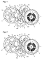
- Said dead second cam 12 turning, allows the front ramp 18a of a tooth 18 to act on the pallet of the upper probe arm 20a of the dead second anchor 20, so that said anchor 20 tilts around its pivot point A to exit, to the opposite, the pallet of the lower exhaust arm 20d of the second dead anchor 20 of the toothing of the jumping member 6.
- step 0 represented on the figure 1
- step 5 the fifth step of the ramp before 18a of the tooth concerned (ie for an angle of rotation of the dead second cam 12 of 15 °, cf. figure 5 )
- the pallet of the lower exhaust arm 20d does not come out of the toothing of the jumping member 6, regardless of the clearance clearance.
- the asymmetric profile of each tooth 18 of the second dead cam 12 is such that the raising of the anchor is done progressively with the pallet of the upper probe arm 20a while the pallet of the lower probe arm 20b descends without touching the dead second cam 12.
- the jumping member 6 has not yet jumped, and is still blocked by the pallet of the lower exhaust arm 20d.
- the pallet of the upper probe arm 20a has arrived at the fifth step of the ramp before 18a, if the dead second anchor 20 undergoes a catch of play following a shock for example, the pallet of the lower probe arm 20b is positioned at the contact 18b of the corresponding tooth 18 of the dead second cam 12, as shown in FIG. figure 3 .
- the jumping organ 6 has not jumped, but remains at the limit of jumping.
- the jumping member 6 jumps when the pallet of the upper feeler arm 20a moves between the fifth and sixth steps.
- the movement of the dead second anchor is a reciprocating movement that releases, tooth by tooth, the jumping member 6, once with the pallet of the upper exhaust arm 20c, then with the pallet of the arm lower exhaust 20d, successively and alternately.
- the dead second indicator advances in increments of 1 second.
- the second dead mechanism of the invention allows for precise jumps every second with less energy consumption.
- the mechanism of the invention is powered by the same source of energy as the finishing gear. A second source of energy is not necessary.
- the arrangement on separate axes of the jumper member and the dead second cam provides optimized shapes for the vanes of the exhaust arms on the one hand and for the pallets of the feeler arms on the other hand , in connection with optimized shapes of the teeth of the dead second cam.
- the energy consumption due to the spiral spring between the second wheel and the jumping member is almost zero. In particular, the higher the slope of the front ramp of the teeth of the second dead cam will be high on the last three steps of the tooth, the more the jump will be marked and therefore accurate.
- a lower slope on the first three steps of the tooth makes the angular pitch of the second dead anchor relatively low over this period.
- the torque consumption is therefore low.
- the slope on the last three steps is on the contrary more important but must however remain measured in order to avoid over-consumption of torque on the mobile cam second dead.
- the angular pitch of the dead second anchor is higher on the last three steps, which allows the jump to be performed over a larger measurement range, and consequently increases the jump accuracy.
- the use of a dead second cam having only 10 teeth makes it possible to obtain larger angular steps, and thus less imperceptible jumps in the dead second cam.
- the radius forming the flank of the toothing of the jumping member is chosen to be concentric and equal to that of the second dead anchor with which it is in contact.
- the arrangement on separate axes of the jumping member and the second dead cam makes it possible not to add a large number of parts on the same axis and therefore to limit the accumulation of tolerances and the misalignment of the mobiles, unlike to the coaxial mechanisms of the prior art.
- the precision on the axis of the jumping member is therefore greater while simplifying the assembly of parts.
- the second dead mechanism described above can be adapted to another unit of time than the second.
- the drive mechanism of a jumping member according to the invention can be adapted to the display of any unit of time: second, minute, ten seconds, ten minutes, etc. To do this, the skilled person knows how to adapt accordingly the number of teeth on the cam and the jumping member, as well as the gear ratios in the gear train.
Landscapes
- Physics & Mathematics (AREA)
- General Physics & Mathematics (AREA)
- Transmission Devices (AREA)
Priority Applications (8)
| Application Number | Priority Date | Filing Date | Title |
|---|---|---|---|
| EP14197490.7A EP3032348A1 (de) | 2014-12-11 | 2014-12-11 | Antriebsmechanismus eines organs, das sich in sprüngen bewegt |
| EP15196125.7A EP3032349B1 (de) | 2014-12-11 | 2015-11-24 | Antriebsmechanismus eines organs, das sich in sprüngen bewegt |
| CH01723/15A CH710477A2 (fr) | 2014-12-11 | 2015-11-26 | Mécanisme d'entrainement d'un organe sautant et pièce d'horlogerie comprenant un tel mécanisme. |
| US14/958,162 US9429914B2 (en) | 2014-12-11 | 2015-12-03 | Mechanism for driving a jumping element |
| JP2015240805A JP6297535B2 (ja) | 2014-12-11 | 2015-12-10 | ジャンピング要素を駆動するための機構 |
| RU2015153133A RU2739148C2 (ru) | 2014-12-11 | 2015-12-10 | Механизм для приведения в действие проскакивающего элемента |
| CN201510917441.2A CN105700324B (zh) | 2014-12-11 | 2015-12-10 | 用于驱动跳变元件的机构 |
| HK16114156A HK1225816B (zh) | 2014-12-11 | 2016-12-13 | 用於驅動跳變元件的機構 |
Applications Claiming Priority (1)
| Application Number | Priority Date | Filing Date | Title |
|---|---|---|---|
| EP14197490.7A EP3032348A1 (de) | 2014-12-11 | 2014-12-11 | Antriebsmechanismus eines organs, das sich in sprüngen bewegt |
Publications (1)
| Publication Number | Publication Date |
|---|---|
| EP3032348A1 true EP3032348A1 (de) | 2016-06-15 |
Family
ID=52101130
Family Applications (1)
| Application Number | Title | Priority Date | Filing Date |
|---|---|---|---|
| EP14197490.7A Withdrawn EP3032348A1 (de) | 2014-12-11 | 2014-12-11 | Antriebsmechanismus eines organs, das sich in sprüngen bewegt |
Country Status (1)
| Country | Link |
|---|---|
| EP (1) | EP3032348A1 (de) |
Cited By (2)
| Publication number | Priority date | Publication date | Assignee | Title |
|---|---|---|---|---|
| US10579018B2 (en) | 2017-03-30 | 2020-03-03 | Richemont International S.A. | Timepiece with digital time display |
| CN112433457A (zh) * | 2019-08-26 | 2021-03-02 | 布朗潘有限公司 | 两个齿轮系的脱离 |
Citations (10)
| Publication number | Priority date | Publication date | Assignee | Title |
|---|---|---|---|---|
| CH311865A (fr) | 1953-08-12 | 1955-12-15 | Rolex Montres | Pièce d'horlogerie à seconde morte. |
| CH511471A (fr) * | 1966-12-21 | 1971-04-30 | Seiko Instr & Electronics | Pièce d'horlogerie à affichage digital |
| FR2257935A1 (de) * | 1973-08-20 | 1975-08-08 | Ebauchesfabrik Eta Ag | |
| US20040156273A1 (en) * | 2003-02-10 | 2004-08-12 | Jean-Francois Mojon | Constant-force device for indirect-second watches |
| EP1772783A1 (de) * | 2005-10-10 | 2007-04-11 | Montres Breguet S.A. | Uhrwerkvorrichtung mit konstanter Kraft |
| EP2068210A2 (de) * | 2007-12-04 | 2009-06-10 | Chronode SA | Auslösevorrichtung |
| EP2166419A1 (de) * | 2008-09-18 | 2010-03-24 | Agenhor SA | Uhrwerk, das eine Konstantkraftvorrichtung aufweist |
| WO2011113757A1 (fr) * | 2010-03-17 | 2011-09-22 | Complitime Sa | Mouvement pour piece d'horlogerie a remontoir d'egalite |
| EP2397920A1 (de) * | 2010-06-17 | 2011-12-21 | Blancpain S.A. | Mechanismus für springendes Tourbillon-Gestell oder Karussell-Gestell |
| CH707743A2 (fr) * | 2013-03-12 | 2014-09-15 | Seiko Instr Inc | Dispositif d'ajustement de couple, mouvement et pièce d'horlogerie mécanique. |
-
2014
- 2014-12-11 EP EP14197490.7A patent/EP3032348A1/de not_active Withdrawn
Patent Citations (10)
| Publication number | Priority date | Publication date | Assignee | Title |
|---|---|---|---|---|
| CH311865A (fr) | 1953-08-12 | 1955-12-15 | Rolex Montres | Pièce d'horlogerie à seconde morte. |
| CH511471A (fr) * | 1966-12-21 | 1971-04-30 | Seiko Instr & Electronics | Pièce d'horlogerie à affichage digital |
| FR2257935A1 (de) * | 1973-08-20 | 1975-08-08 | Ebauchesfabrik Eta Ag | |
| US20040156273A1 (en) * | 2003-02-10 | 2004-08-12 | Jean-Francois Mojon | Constant-force device for indirect-second watches |
| EP1772783A1 (de) * | 2005-10-10 | 2007-04-11 | Montres Breguet S.A. | Uhrwerkvorrichtung mit konstanter Kraft |
| EP2068210A2 (de) * | 2007-12-04 | 2009-06-10 | Chronode SA | Auslösevorrichtung |
| EP2166419A1 (de) * | 2008-09-18 | 2010-03-24 | Agenhor SA | Uhrwerk, das eine Konstantkraftvorrichtung aufweist |
| WO2011113757A1 (fr) * | 2010-03-17 | 2011-09-22 | Complitime Sa | Mouvement pour piece d'horlogerie a remontoir d'egalite |
| EP2397920A1 (de) * | 2010-06-17 | 2011-12-21 | Blancpain S.A. | Mechanismus für springendes Tourbillon-Gestell oder Karussell-Gestell |
| CH707743A2 (fr) * | 2013-03-12 | 2014-09-15 | Seiko Instr Inc | Dispositif d'ajustement de couple, mouvement et pièce d'horlogerie mécanique. |
Cited By (3)
| Publication number | Priority date | Publication date | Assignee | Title |
|---|---|---|---|---|
| US10579018B2 (en) | 2017-03-30 | 2020-03-03 | Richemont International S.A. | Timepiece with digital time display |
| CN112433457A (zh) * | 2019-08-26 | 2021-03-02 | 布朗潘有限公司 | 两个齿轮系的脱离 |
| CN112433457B (zh) * | 2019-08-26 | 2022-07-08 | 奥米加股份有限公司 | 两个齿轮系的脱离 |
Similar Documents
| Publication | Publication Date | Title |
|---|---|---|
| EP3032349B1 (de) | Antriebsmechanismus eines organs, das sich in sprüngen bewegt | |
| EP2729849B1 (de) | Uhr | |
| CH709508A2 (fr) | Mouvement horloger muni d'un mécanisme d'entraînement d'un indicateur analogique à déplacement périodique ou intermittent. | |
| EP2407830A1 (de) | Uhr | |
| EP3070536A1 (de) | Uhrwerk, das eine antriebsvorrichtung einer analogen anzeige umfasst | |
| EP3070537A1 (de) | Zeitbasiseinheit, die eine hemmung mit direktimpuls und konstanter kraft umfasst | |
| EP2952973B1 (de) | Uhrenmechanismus zum augenblicklichen umspringen | |
| EP3032348A1 (de) | Antriebsmechanismus eines organs, das sich in sprüngen bewegt | |
| EP3182217A1 (de) | Mechanismus zum einstellen des kupplungsverhältnisses zwischen triebfedern einer uhr | |
| CH710463A2 (fr) | Mécanisme d'entraînement d'un organe sautant et pièce d'horlogerie comprenant un tel mécanisme. | |
| CH710108B1 (fr) | Mécanisme à force constante, mouvement et pièce d'horlogerie. | |
| EP4194962A1 (de) | Uhrwerk mit einem regulierungsorgan, das mit mitteln zur variablen einstellung der neigung versehen ist | |
| CH707742A2 (fr) | Système balancier-spiral, mouvement de pièce d'horlogerie et pièce d'horlogerie. | |
| EP3705949A1 (de) | Drehmomentbegrenzungsmechanismus eines uhrwerks | |
| EP2735920B1 (de) | Uhrwerk, das mit einem hohlen und drehbaren 3D-Element ausgestattet ist | |
| CH713705A2 (fr) | Mécanisme à force constante, mouvement de pièce d'horlogerie et pièce d'horlogerie. | |
| EP1960846B1 (de) | Uhrwerk | |
| EP3874331B1 (de) | Oszillierendes gewicht mit variabler geometrie für einen uhrwerkmechanismus | |
| EP3619579A1 (de) | Taktvorrichtung mit positionierungselement | |
| CH718986A1 (fr) | Mouvement horloger comprenant un dispositif de suspension de l'oscillateur. | |
| CH713531A2 (fr) | Echappement, mouvement de pièce d'horlogerie et pièce d'horlogerie. | |
| EP4254079A1 (de) | Mechanismus zur anzeige der mondphasen für uhr | |
| EP3825783A1 (de) | Einstellmechanismus eines stegs einer uhr | |
| CH720089A1 (fr) | Mobile pour un mécanisme horloger, mécanisme horloger, mouvement horloger, et pièce d'horlogerie correspondants | |
| CH719558A2 (fr) | Mouvement d'horlogerie comportant un mécanisme d'affichage des phases de lune. |
Legal Events
| Date | Code | Title | Description |
|---|---|---|---|
| PUAI | Public reference made under article 153(3) epc to a published international application that has entered the european phase |
Free format text: ORIGINAL CODE: 0009012 |
|
| AK | Designated contracting states |
Kind code of ref document: A1 Designated state(s): AL AT BE BG CH CY CZ DE DK EE ES FI FR GB GR HR HU IE IS IT LI LT LU LV MC MK MT NL NO PL PT RO RS SE SI SK SM TR |
|
| AX | Request for extension of the european patent |
Extension state: BA ME |
|
| STAA | Information on the status of an ep patent application or granted ep patent |
Free format text: STATUS: THE APPLICATION IS DEEMED TO BE WITHDRAWN |
|
| 18D | Application deemed to be withdrawn |
Effective date: 20161216 |