EP3032253B1 - Unterbrechungsfreier fluidstrom während der modulation des fluids - Google Patents
Unterbrechungsfreier fluidstrom während der modulation des fluids Download PDFInfo
- Publication number
- EP3032253B1 EP3032253B1 EP15199320.1A EP15199320A EP3032253B1 EP 3032253 B1 EP3032253 B1 EP 3032253B1 EP 15199320 A EP15199320 A EP 15199320A EP 3032253 B1 EP3032253 B1 EP 3032253B1
- Authority
- EP
- European Patent Office
- Prior art keywords
- fluid
- flow path
- fluidic
- accommodation volume
- processing device
- Prior art date
- Legal status (The legal status is an assumption and is not a legal conclusion. Google has not performed a legal analysis and makes no representation as to the accuracy of the status listed.)
- Active
Links
- 0 CC[C@@](C)[C@@]1(C2C1)C(C)CC2(CN)C1C(*2)[C@]2C[C@](*)CCC1 Chemical compound CC[C@@](C)[C@@]1(C2C1)C(C)CC2(CN)C1C(*2)[C@]2C[C@](*)CCC1 0.000 description 2
- CXDFPKBRDGFONF-LUAWRHEFSA-N C/C(/CO)=C1/C=C(CCCN=O)C=C1 Chemical compound C/C(/CO)=C1/C=C(CCCN=O)C=C1 CXDFPKBRDGFONF-LUAWRHEFSA-N 0.000 description 1
- IWTZAMAMPYFKLA-SNAWJCMRSA-N O=N/C=C1\C=CC1 Chemical compound O=N/C=C1\C=CC1 IWTZAMAMPYFKLA-SNAWJCMRSA-N 0.000 description 1
Images




Classifications
-
- G—PHYSICS
- G01—MEASURING; TESTING
- G01N—INVESTIGATING OR ANALYSING MATERIALS BY DETERMINING THEIR CHEMICAL OR PHYSICAL PROPERTIES
- G01N30/00—Investigating or analysing materials by separation into components using adsorption, absorption or similar phenomena or using ion-exchange, e.g. chromatography or field flow fractionation
- G01N30/02—Column chromatography
- G01N30/26—Conditioning of the fluid carrier; Flow patterns
- G01N30/28—Control of physical parameters of the fluid carrier
- G01N30/32—Control of physical parameters of the fluid carrier of pressure or speed
-
- F—MECHANICAL ENGINEERING; LIGHTING; HEATING; WEAPONS; BLASTING
- F16—ENGINEERING ELEMENTS AND UNITS; GENERAL MEASURES FOR PRODUCING AND MAINTAINING EFFECTIVE FUNCTIONING OF MACHINES OR INSTALLATIONS; THERMAL INSULATION IN GENERAL
- F16K—VALVES; TAPS; COCKS; ACTUATING-FLOATS; DEVICES FOR VENTING OR AERATING
- F16K99/00—Subject matter not provided for in other groups of this subclass
- F16K99/0001—Microvalves
- F16K99/0003—Constructional types of microvalves; Details of the cutting-off member
- F16K99/0028—Valves having multiple inlets or outlets
-
- B—PERFORMING OPERATIONS; TRANSPORTING
- B01—PHYSICAL OR CHEMICAL PROCESSES OR APPARATUS IN GENERAL
- B01D—SEPARATION
- B01D15/00—Separating processes involving the treatment of liquids with solid sorbents; Apparatus therefor
- B01D15/08—Selective adsorption, e.g. chromatography
- B01D15/10—Selective adsorption, e.g. chromatography characterised by constructional or operational features
- B01D15/18—Selective adsorption, e.g. chromatography characterised by constructional or operational features relating to flow patterns
-
- B—PERFORMING OPERATIONS; TRANSPORTING
- B01—PHYSICAL OR CHEMICAL PROCESSES OR APPARATUS IN GENERAL
- B01D—SEPARATION
- B01D15/00—Separating processes involving the treatment of liquids with solid sorbents; Apparatus therefor
- B01D15/08—Selective adsorption, e.g. chromatography
- B01D15/10—Selective adsorption, e.g. chromatography characterised by constructional or operational features
-
- B—PERFORMING OPERATIONS; TRANSPORTING
- B01—PHYSICAL OR CHEMICAL PROCESSES OR APPARATUS IN GENERAL
- B01D—SEPARATION
- B01D15/00—Separating processes involving the treatment of liquids with solid sorbents; Apparatus therefor
- B01D15/08—Selective adsorption, e.g. chromatography
- B01D15/10—Selective adsorption, e.g. chromatography characterised by constructional or operational features
- B01D15/18—Selective adsorption, e.g. chromatography characterised by constructional or operational features relating to flow patterns
- B01D15/1864—Selective adsorption, e.g. chromatography characterised by constructional or operational features relating to flow patterns using two or more columns
- B01D15/1871—Selective adsorption, e.g. chromatography characterised by constructional or operational features relating to flow patterns using two or more columns placed in series
- B01D15/1878—Selective adsorption, e.g. chromatography characterised by constructional or operational features relating to flow patterns using two or more columns placed in series for multi-dimensional chromatography
-
- B—PERFORMING OPERATIONS; TRANSPORTING
- B01—PHYSICAL OR CHEMICAL PROCESSES OR APPARATUS IN GENERAL
- B01L—CHEMICAL OR PHYSICAL LABORATORY APPARATUS FOR GENERAL USE
- B01L3/00—Containers or dishes for laboratory use, e.g. laboratory glassware; Droppers
- B01L3/50—Containers for the purpose of retaining a material to be analysed, e.g. test tubes
- B01L3/502—Containers for the purpose of retaining a material to be analysed, e.g. test tubes with fluid transport, e.g. in multi-compartment structures
- B01L3/5027—Containers for the purpose of retaining a material to be analysed, e.g. test tubes with fluid transport, e.g. in multi-compartment structures by integrated microfluidic structures, i.e. dimensions of channels and chambers are such that surface tension forces are important, e.g. lab-on-a-chip
- B01L3/50273—Containers for the purpose of retaining a material to be analysed, e.g. test tubes with fluid transport, e.g. in multi-compartment structures by integrated microfluidic structures, i.e. dimensions of channels and chambers are such that surface tension forces are important, e.g. lab-on-a-chip characterised by the means or forces applied to move the fluids
-
- G—PHYSICS
- G01—MEASURING; TESTING
- G01N—INVESTIGATING OR ANALYSING MATERIALS BY DETERMINING THEIR CHEMICAL OR PHYSICAL PROPERTIES
- G01N27/00—Investigating or analysing materials by the use of electric, electrochemical, or magnetic means
- G01N27/26—Investigating or analysing materials by the use of electric, electrochemical, or magnetic means by investigating electrochemical variables; by using electrolysis or electrophoresis
- G01N27/416—Systems
- G01N27/447—Systems using electrophoresis
- G01N27/44756—Apparatus specially adapted therefor
- G01N27/44791—Microapparatus
-
- G—PHYSICS
- G01—MEASURING; TESTING
- G01N—INVESTIGATING OR ANALYSING MATERIALS BY DETERMINING THEIR CHEMICAL OR PHYSICAL PROPERTIES
- G01N30/00—Investigating or analysing materials by separation into components using adsorption, absorption or similar phenomena or using ion-exchange, e.g. chromatography or field flow fractionation
- G01N30/02—Column chromatography
- G01N30/26—Conditioning of the fluid carrier; Flow patterns
- G01N30/38—Flow patterns
-
- G—PHYSICS
- G01—MEASURING; TESTING
- G01N—INVESTIGATING OR ANALYSING MATERIALS BY DETERMINING THEIR CHEMICAL OR PHYSICAL PROPERTIES
- G01N30/00—Investigating or analysing materials by separation into components using adsorption, absorption or similar phenomena or using ion-exchange, e.g. chromatography or field flow fractionation
- G01N30/02—Column chromatography
- G01N30/26—Conditioning of the fluid carrier; Flow patterns
- G01N30/38—Flow patterns
- G01N30/46—Flow patterns using more than one column
-
- G—PHYSICS
- G01—MEASURING; TESTING
- G01N—INVESTIGATING OR ANALYSING MATERIALS BY DETERMINING THEIR CHEMICAL OR PHYSICAL PROPERTIES
- G01N30/00—Investigating or analysing materials by separation into components using adsorption, absorption or similar phenomena or using ion-exchange, e.g. chromatography or field flow fractionation
- G01N30/02—Column chromatography
- G01N30/26—Conditioning of the fluid carrier; Flow patterns
- G01N30/38—Flow patterns
- G01N30/46—Flow patterns using more than one column
- G01N30/461—Flow patterns using more than one column with serial coupling of separation columns
- G01N30/465—Flow patterns using more than one column with serial coupling of separation columns with specially adapted interfaces between the columns
-
- G—PHYSICS
- G01—MEASURING; TESTING
- G01N—INVESTIGATING OR ANALYSING MATERIALS BY DETERMINING THEIR CHEMICAL OR PHYSICAL PROPERTIES
- G01N30/00—Investigating or analysing materials by separation into components using adsorption, absorption or similar phenomena or using ion-exchange, e.g. chromatography or field flow fractionation
- G01N30/02—Column chromatography
- G01N30/26—Conditioning of the fluid carrier; Flow patterns
- G01N30/38—Flow patterns
- G01N30/46—Flow patterns using more than one column
- G01N30/466—Flow patterns using more than one column with separation columns in parallel
-
- G—PHYSICS
- G01—MEASURING; TESTING
- G01N—INVESTIGATING OR ANALYSING MATERIALS BY DETERMINING THEIR CHEMICAL OR PHYSICAL PROPERTIES
- G01N30/00—Investigating or analysing materials by separation into components using adsorption, absorption or similar phenomena or using ion-exchange, e.g. chromatography or field flow fractionation
- G01N30/02—Column chromatography
- G01N30/26—Conditioning of the fluid carrier; Flow patterns
- G01N30/38—Flow patterns
- G01N30/46—Flow patterns using more than one column
- G01N30/468—Flow patterns using more than one column involving switching between different column configurations
-
- B—PERFORMING OPERATIONS; TRANSPORTING
- B01—PHYSICAL OR CHEMICAL PROCESSES OR APPARATUS IN GENERAL
- B01D—SEPARATION
- B01D15/00—Separating processes involving the treatment of liquids with solid sorbents; Apparatus therefor
- B01D15/08—Selective adsorption, e.g. chromatography
- B01D15/26—Selective adsorption, e.g. chromatography characterised by the separation mechanism
- B01D15/40—Selective adsorption, e.g. chromatography characterised by the separation mechanism using supercritical fluid as mobile phase or eluent
-
- B—PERFORMING OPERATIONS; TRANSPORTING
- B01—PHYSICAL OR CHEMICAL PROCESSES OR APPARATUS IN GENERAL
- B01L—CHEMICAL OR PHYSICAL LABORATORY APPARATUS FOR GENERAL USE
- B01L2400/00—Moving or stopping fluids
- B01L2400/04—Moving fluids with specific forces or mechanical means
- B01L2400/0475—Moving fluids with specific forces or mechanical means specific mechanical means and fluid pressure
-
- F—MECHANICAL ENGINEERING; LIGHTING; HEATING; WEAPONS; BLASTING
- F16—ENGINEERING ELEMENTS AND UNITS; GENERAL MEASURES FOR PRODUCING AND MAINTAINING EFFECTIVE FUNCTIONING OF MACHINES OR INSTALLATIONS; THERMAL INSULATION IN GENERAL
- F16K—VALVES; TAPS; COCKS; ACTUATING-FLOATS; DEVICES FOR VENTING OR AERATING
- F16K99/00—Subject matter not provided for in other groups of this subclass
- F16K2099/0082—Microvalves adapted for a particular use
- F16K2099/0084—Chemistry or biology, e.g. "lab-on-a-chip" technology
-
- G—PHYSICS
- G01—MEASURING; TESTING
- G01N—INVESTIGATING OR ANALYSING MATERIALS BY DETERMINING THEIR CHEMICAL OR PHYSICAL PROPERTIES
- G01N30/00—Investigating or analysing materials by separation into components using adsorption, absorption or similar phenomena or using ion-exchange, e.g. chromatography or field flow fractionation
- G01N30/02—Column chromatography
- G01N30/04—Preparation or injection of sample to be analysed
- G01N30/16—Injection
- G01N30/20—Injection using a sampling valve
- G01N2030/202—Injection using a sampling valve rotary valves
-
- G—PHYSICS
- G01—MEASURING; TESTING
- G01N—INVESTIGATING OR ANALYSING MATERIALS BY DETERMINING THEIR CHEMICAL OR PHYSICAL PROPERTIES
- G01N30/00—Investigating or analysing materials by separation into components using adsorption, absorption or similar phenomena or using ion-exchange, e.g. chromatography or field flow fractionation
- G01N30/02—Column chromatography
- G01N30/26—Conditioning of the fluid carrier; Flow patterns
- G01N30/28—Control of physical parameters of the fluid carrier
- G01N30/32—Control of physical parameters of the fluid carrier of pressure or speed
- G01N2030/328—Control of physical parameters of the fluid carrier of pressure or speed valves, e.g. check valves of pumps
-
- G—PHYSICS
- G01—MEASURING; TESTING
- G01N—INVESTIGATING OR ANALYSING MATERIALS BY DETERMINING THEIR CHEMICAL OR PHYSICAL PROPERTIES
- G01N30/00—Investigating or analysing materials by separation into components using adsorption, absorption or similar phenomena or using ion-exchange, e.g. chromatography or field flow fractionation
- G01N30/02—Column chromatography
- G01N30/26—Conditioning of the fluid carrier; Flow patterns
- G01N30/38—Flow patterns
- G01N2030/382—Flow patterns flow switching in a single column
- G01N2030/385—Flow patterns flow switching in a single column by switching valves
Definitions
- One or more fluidic valves may form part of a liquid chromatography apparatus.
- An example for such a valve for liquid separation is disclosed in US 7,036,526 B1 . Further reference is made to patent applications with US application number 61/834,883 and PCT application number PCT/IB2013/054885 published after the priority date of the present application.
- a fluid processing device for processing fluid (i.e. a liquid and/or a gas, optionally comprising solid particles)
- the fluid processing device comprises a first fluid drive unit (such as a first pump, in particular a high pressure pump; however, the first fluid drive unit may also comprise or be a reactor tank or a pipe) configured for driving a first fluid along a first flow path, a second fluid drive unit (such as a second pump, in particular a further high pressure pump) configured for driving a second fluid along a second flow path (wherein the second flow path may be at a different pressure level than the first flow path), and a fluidic switch fluidically coupled to the first flow path and to the second flow path and configured for being switchable (for instance under control of a control unit of the fluid processing device, such as a processor) for transferring first fluid (for instance for subsequently transferring individual packets of first fluid) from the first flow path into the second flow path without interruption of (i.e. continuously maintaining) fluid
- the first flow path and the second flow path are fluidically decoupled from each other over their entire lengths (i.e. their entire courses), except within the fluidic switch, thereby allowing a transfer of fluid from the first fluid path into the second fluid path only within the fluidic switch.
- the course of the first fluid path may include the first fluid drive unit, a first separating unit, the fluidic switch, and a waste arranged downstream the fluidic switch.
- the course of the second fluid path may include the second fluid drive unit, the fluidic switch, a second separating unit and a further waste.
- the first flow path meets the second flow path exclusively within the fluidic switch according to the described embodiment.
- fluid accommodation volumes for example sample loops each connected to two assigned ports of the fluidic switch
- fluid accommodation volumes or bypass paths which can be selectively brought in fluid communication with certain sections of the first flow path or the second flow path, respectively, to prevent interruption of the continuous flow in any of the flow paths upon switching.
- the fluid processing device is configured as a fluid reactor device configured for effecting a reaction of the first fluid with a reaction medium, in particular a reaction medium from a reactor unit (see for instance Figure 2 to Figure 6 ).
- a fluid reactor can be arranged in the first flow path and can be capable of carrying out a for instance chemical or biological reaction with the first fluid.
- the correspondingly modified first fluid can be, in portions or sections or packets, be introduced into the second flow path, for example for separation of the modified first fluid in fractions, for interaction with another second fluid or for other analysis purposes.
- a first separation unit such as a chromatographic separation column may be provided in the first flow path.
- a fluidic sample to be separated may be injected by an injector into mobile phase driven by the first fluid drive unit.
- the mixture of the fluidic sample and the mobile phase, together forming the first fluid may then be separated, for instance chromatographically, for example by carrying out a gradient run (during which a solvent composition of the mobile phase is modified in accordance with a gradient profile).
- this second separation can be carried out in the second flow path.
- packets of the first fluid are to be transferred from the first flow path into the second flow path.
- the separation unit(s) preferably comprise(s) a chromatographic column (see for instance http://en.wikipedia.org/wiki/Column chromatography ) providing the stationary phase.
- the column might be a glass or steel tube (for instance with a diameter from 50 ⁇ m to 5 mm and a length of 1 cm to 1 m) or a microfluidic column (as disclosed for instance in EP 1577012 or the Agilent 1200 Series HPLC-Chip/MS System provided by the applicant Agilent Technologies.
- a slurry can be prepared with a powder of the stationary phase and then poured and pressed into the column. The individual sample components are retained by the stationary phase differently and separate from each other while they are propagating at different speeds through the column with the eluent.
- Embodiments of the invention can be partly or entirely embodied or supported by one or more suitable software programs, which can be stored on or otherwise provided by any kind of data carrier, and which might be executed in or by any suitable data processing unit.
- Software programs or routines can be preferably applied in or by the control unit.
- the separation unit of any of the stages may be filled with a separating material.
- a separating material which may also be denoted as a stationary phase, may be any material which allows a different degree of interaction with sample components so as to be capable of separating different components of such a sample.
- the separating material may be a liquid chromatography column filling material or packing material comprising at least one of the group consisting of polystyrene, zeolite, polyvinylalcohol, polytetrafluorethylene, glass, polymeric powder, carbon, graphite, alumina, zirconia, silicon dioxide, and silica gel, or any of above with a chemically modified (coated, capped etc) surface.
- any packing material can be used that has material properties allowing a sample passing through this material to be separated into different components, for instance due to different degrees of interactions or affinities between the packing material and fractions of the analyte.
- a data processing unit, control unit or processor 70 which can be a conventional PC or workstation, might be coupled (as indicated by the dotted arrows) to one or more of the devices in the fluid processing device 10 in order to receive information and/or control operation.
- the processor 70 might control operation of the fluid drive units 20, 20' (e.g. setting control parameters) and receive therefrom information regarding the actual working conditions (such as output pressure, flow rate, etc. at an outlet of the pump).
- the processor 70 might also control operation of the solvent supply 25, 25' (e.g. setting the solvent/s or solvent mixture to be supplied) and/or the degasser 27, 27' (e.g.
- the fluidic switch 90 is switchable between different fluid switching states for transferring the first fluid from the first flow path 85 into the second flow path 86 in such a manner that in a transition period during switching between the different fluid switching states fluid flow along the first flow path 85 and along the second flow path 86 continue uninterrupted.
- the fluid processing device 10 shown in Figure 1 is configured as a two-dimensional sample separation device configured for separating the first fluid into fractions (which can be detected by detector 55) and at least one of the fractions of the transferred first fluid into sub-fractions (which can be detected by detector 50).
- the fluidic switch 90 is further configured for being switchable between the plurality of fluid switching states so that the fluid flow at a fluidic outlet of the first dimension (i.e.
- the first fluid flowing along first flow path 85 shall be brought in interaction with a medium or substrate in reactor unit 206 so as to initiate or trigger a for instance chemical (or biological) reaction between the first fluid and the reactor unit 206.
- the so modified first fluid shall be introduced in packets into the second flow path 86 for analysis by separation unit 30'.
- the different fluidic fractions in the manipulated first fluid shall be analyzed, for instance by liquid chromatography, in the separation unit 30'.
- packets of the manipulated first fluid are temporarily stored in the first or second accommodation volumes 200, 202 and are subsequently introduced, after switching of the fluidic switch 90, in the second flow path 86.
- a third fluid accommodation volume 204 is provided and is connected to two ports of the fluidic switch 90.
- manipulated first fluid which has been introduced into first fluid accommodation volume 200 beforehand is properly analyzed in the second flow path 86.
- the second fluid drive unit 20' drives a mobile phase and carries the manipulated first fluid temporarily accommodated in the first fluid accommodation volume 200 through the separation unit 30' towards a detector (not shown) in the second flow path 86.
- a detector not shown
- an analysis of the manipulated first fluid is carried out according to Figure 2 .
- Figure 3 which differs from Figure 2 in that the manipulated first fluid has been temporarily stored in the second fluid accommodation volume 202 and is now transported towards the separation unit 30' in the second flow path 86.
- Figure 7 to Figure 11 show operation modes of the illustrated fluid processing device 10 corresponding to the operation modes shown in Figure 2 to Figure 6 .
- the fluid processing device 10 according to Figure 7 to Figure 11 relates to two-dimensional sample separation.
- a first separation dimension mobile phase is pumped by the first fluid drive unit 20 and the fluidic sample is added to it in the injector 40.
- the first fluid containing fluidic sample and the mobile phase is then separated into fractions in the separation unit 30.
- the separated fractions are detected by the detector 55 upstream of the fluidic switch 90.
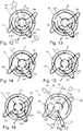
- Figure 14 (corresponding to Figure 4 and Figure 9 ): jumper loop (third fluid accommodation volume 204) alone in the second dimension, both loops (i.e. first fluid accommodation volume 200 and second fluid accommodation volume 202) in the first dimension
- Pos A+Pos 3 corresponds to Figure 7 .
- Pos A+Pos 1 corresponds to Figure 8 .
- Pos B+Pos 2 corresponds to Figure 9 .
- Pos B+Pos 1 corresponds to Figure 11 .
- Pos B+Pos 3 corresponds to Figure 10 .
Landscapes
- Chemical & Material Sciences (AREA)
- Analytical Chemistry (AREA)
- Health & Medical Sciences (AREA)
- Life Sciences & Earth Sciences (AREA)
- General Health & Medical Sciences (AREA)
- Physics & Mathematics (AREA)
- Biochemistry (AREA)
- General Physics & Mathematics (AREA)
- Immunology (AREA)
- Pathology (AREA)
- Chemical Kinetics & Catalysis (AREA)
- Dispersion Chemistry (AREA)
- Engineering & Computer Science (AREA)
- General Engineering & Computer Science (AREA)
- Molecular Biology (AREA)
- Hematology (AREA)
- Clinical Laboratory Science (AREA)
- Mechanical Engineering (AREA)
- Electrochemistry (AREA)
- Treatment Of Liquids With Adsorbents In General (AREA)
Claims (11)
- Eine Fluidverarbeitungsvorrichtung (10) zum Verarbeiten eines Fluids, wobei die Fluidverarbeitungsvorrichtung (10) aufweist:eine erste Fluid Antriebseinheit (20), welche konfiguriert ist zum Antreiben eines ersten Fluids entlang eines ersten Strömungspfads (85);eine zweite Fluid Antriebseinheit (20'), welche konfiguriert ist zum Antreiben eines zweiten Fluids entlang eines zweiten Strömungspfads (86);einen fluidischen Schalter (90), welcher mit dem ersten Strömungspfad (85) und mit dem zweiten Strömungspfad (86) fluidisch gekoppelt ist, wobei der erste Strömungspfad und der zweite Strömungspfad über ihre gesamten Längen, ausgenommen in dem fluidischen Schalter (90), fluidisch voneinander entkoppelt sind, wobei der fluidische Schalter (90) konfiguriert ist, zwischen verschiedenen Fluid Schaltzuständen schaltbar zu sein zum Übertragen eines ersten Fluids von dem ersten Strömungspfad (85) in den zweiten Strömungspfad (86), ohne eine Unterbrechung des Fluidstroms entlang zumindest eines des ersten Strömungspfads (85) und des zweiten Strömungspfads (86),ein erstes Fluid Aufnahmevolumen (200), ein zweites Fluid Aufnahmevolumen (202) und ein drittes Fluid Aufnahmevolumen (204), wobei jedes davon fluidische Schnittstellen hat, welche mit dem fluidischen Schalter (90) fluidisch gekoppelt sind, und welche zum Zusammenwirken konfiguriert sind, um einen Fluidstrom unabhängig entlang des ersten Strömungspfads (85) und entlang des zweiten Strömungspfads (86) via zumindest eines der Fluid Aufnahmevolumen (200, 202, 204) aufrechtzuerhalten, während der fluidische Schalter (90) zum Übertragen des ersten Fluids von dem ersten Strömungspfad (85) in den zweiten Strömungspfad (86) geschaltet wird;wobei der fluidische Schalter (90) konfiguriert ist, in einen Fluidverarbeitung Schaltzustand schaltbar zu sein, in welchem der erste Strömungspfad (85) eines von dem ersten Fluid Aufnahmevolumen (200) oder dem zweiten Fluid Aufnahmevolumen (202) enthält, während der zweite Strömungspfad (86) das jeweils andere des ersten Fluid Aufnahmevolumens (200) oder des zweiten Fluid Aufnahmevolumens (202) enthält, während keiner des ersten Strömungspfads (85) oder des zweiten Strömungspfads (86) das dritte Fluid Aufnahmevolumen (204) enthält,dadurch gekennzeichnet, dassder fluidische Schalter (90) konfiguriert ist, in einen ersten Fluidteilungsschaltzustand schaltbar zu sein, in welchem der erste Strömungspfad (85) sowohl das erste Fluid Aufnahmevolumen (200) als auch das zweite Fluid Aufnahmevolumen (202) enthält, um dadurch das erste Fluid aufzuteilen, durch das erste Fluid Aufnahmevolumen (200) und durch das zweite Fluid Aufnahmevolumen (202) zu fließen, während der zweite Strömungspfad (86) das dritte Fluid Aufnahmevolumen (204) enthält, undder fluidische Schalter (90) konfiguriert ist, in einen zweiten Fluidteilungsschaltzustand schaltbar zu sein, in welchem der erste Strömungspfad (85) das erste Fluid Aufnahmevolumen (200) oder das zweite Fluid Aufnahmevolumen (202) enthält, während der zweite Strömungspfad (86) das jeweils andere von dem ersten Fluid Aufnahmevolumen (200) oder dem zweiten Fluid Aufnahmevolumen (202) enthält und zusätzlich das dritte Fluid Aufnahmevolumen (204) enthält, um dadurch das zweite Fluid aufzuteilen, durch das andere von dem ersten Fluid Aufnahmevolumen (200) oder dem zweiten Fluid Aufnahmevolumen (202) und zusätzlich durch das dritte Fluid Aufnahmevolumen (204) zu fließen.
- Die Fluidverarbeitungsvorrichtung (10) gemäß Anspruch 1, wobei der fluidische Schalter (90) zwischen verschiedenen Fluid Schaltzuständen schaltbar ist, zum Übertragen des ersten Fluids von dem ersten Strömungspfad (85) in den zweiten Strömungspfad (86) derartig, dass während einer Übergangsperiode, welche beim Schalten zwischen den verschiedenen Fluid Schaltzuständen auftritt, der Fluidstrom entlang des ersten Strömungspfads (85) und der Fluidstrom entlang des zweiten Strömungspfads (86) ununterbrochen fortbestehen.
- Die Fluidverarbeitungsvorrichtung (10) gemäß Anspruch 1,
wobei zumindest eines von dem ersten Fluid Aufnahmevolumen (200), dem zweiten Fluid Aufnahmevolumen (202) und dem dritten Fluid Aufnahmevolumen (204) als eines aus der Gruppe konfiguriert ist, bestehend aus einem Kapillarabschnitt, welcher zwischen zwei fluidischen Schnittstellen des fluidischen Schalters (90) fluidisch verbunden ist, einer Nut, insbesondere einer radialen Nut, einem Ventilelement des fluidischen Schalters (90) und einem Kanal, insbesondere einem mikrofluidischen Kanal oder einem eingebetteten Kanal, inkorporiert in einem Ventilelement des fluidischen Schalters (90). - Die Fluidverarbeitungsvorrichtung (10) gemäß irgendeinem der Ansprüche 1 bis 3, konfiguriert als eine Probentrennvorrichtung, welche zum Trennen des ersten Fluids, insbesondere zum Trennen des ersten Fluids, welches in den zweiten Strömungspfad (86) zu übertragen ist, konfiguriert ist.
- Die Fluidverarbeitungsvorrichtung (10) gemäß irgendeinem der Ansprüche 1 bis 4, konfiguriert als eine zweidimensionale Probentrennvorrichtung, welche konfiguriert ist zum Trennen, in einer ersten Trenndimension, des ersten Fluids in Fraktionen und, in einer zweiten Trenndimension, zumindest einer Fraktion in dem übertragenen ersten Fluid in Teilfraktionen.
- Die Fluidverarbeitungsvorrichtung (10) gemäß Anspruch 5, wobei der fluidische Schalter (90) konfiguriert ist, zwischen einer Mehrzahl von Fluid Schaltzuständen schaltbar zu sein, so dass ein Fluidstrom bei einem fluidischen Auslass der ersten Trenndimension nie unterbrochen wird und ein Fluidstrom an einem fluidischen Einlass der zweiten Trenndimension nie unterbrochen wird.
- Die Fluidverarbeitungsvorrichtung (10) gemäß irgendeinem der Ansprüche 4 bis 6, aufweisend einen Detektor (55), welcher in dem ersten Strömungspfad (85) stromaufwärts des fluidischen Schalters (90) angeordnet ist und zum Detektieren der getrennten Komponenten oder Fraktionen des ersten Fluids konfiguriert ist.
- Die Fluidverarbeitungsvorrichtung (10) gemäß irgendeinem der Ansprüche 1 bis 7, aufweisend zumindest eines von:die Fluidverarbeitungsvorrichtung (10) weist einen Fluidreaktor (206) auf, welcher zum Durchführen einer chemischen, biochemischen oder biologischen Reaktion in dem ersten Fluid konfiguriert ist, insbesondere wobei der Fluidreaktor (206) eines aus der Gruppe ist, bestehend aus einer Quelle des ersten Fluids, welches in den ersten Strömungspfad (85) transportiert wird, und einem Durchflussreaktor, welcher fluidisch in dem ersten Strömungspfad (85) angeordnet ist;wobei der fluidische Schalter (90) konfiguriert ist, schaltbar zu sein, ohne eine übermäßige Druckänderung in dem ersten Strömungspfad (85) zu bewirken, insbesondere ohne einen Druckanstieg oder einen Druckabfall in dem ersten Strömungspfad (85) stromaufwärts des fluidischen Schalters (90) während einer Schaltoperation zu bewirken;ein fluidischer Kurzschlusspfad (204) ist integriert in oder fluidisch gekoppelt mit dem fluidischen Schalter (90), um das Fluid während eines Schaltintervalls zwischen verschiedenen Fluid Schaltzuständen zu leiten;der fluidische Schalter (90) ist konfiguriert, zwischen einer Mehrzahl von Fluid Schaltzuständen schaltbar zu sein, so dass ein Fluidstrom durch die Fluidverarbeitungsvorrichtung (10) nie unterbrochen wird.
- Die Fluidverarbeitungsvorrichtung (10) gemäß irgendeinem der Ansprüche 1 bis 8, wobei der fluidische Schalter (90) als eines aus der Gruppe konfiguriert ist, welche besteht aus:einer einzelnen fluidischen Schaltvorrichtung aufweisend ein einzelnes fluidisches Ventil mit einem oder mehreren Fluid Aufnahmevolumen (200, 202, 204), wobei jedes davon zwischen zwei Anschlüssen des fluidischen Ventils fluidisch verbunden ist,einer fluidischen Schaltvorrichtung aufweisend eine Mehrzahl von zusammenwirkenden fluidischen Ventilen (1800, 1802) mit zumindest einem fluidischen Ventil mit einem oder mehreren Fluid Aufnahmevolumen (200, 202, 204), wobei jedes davon zwischen zwei Anschlüssen des zumindest einen fluidischen Ventils fluidisch verbunden ist, undeinem fluidischen Ventil aufweisend zumindest drei Schleifen (I, II, III), welche in einem beweglichen Element des fluidischen Ventils inkorporiert sind.
- Die Fluidverarbeitungsvorrichtung (10) gemäß irgendeinem der Ansprüche 1 bis 9, aufweisend zumindest eines der folgenden Merkmale:die Fluidverarbeitungsvorrichtung (10) weist eine Trenneinheit (30) zum Trennen des ersten Fluids in dem ersten Strömungspfad (85) stromaufwärts des fluidischen Schalters (90) auf;die Fluidverarbeitungsvorrichtung (10) weist ferner eine weitere Trenneinheit (30') stromabwärts der zweiten Fluid Antriebseinheit (20') und konfiguriert zum weiteren Trennen des übertragenen ersten Fluids auf;die Fluid Antriebseinheit (20) ist konfiguriert zum Antreiben des ersten Fluids mit einem Druck von zumindest 500 bar, insbesondere von zumindest 1200 bar, weiter insbesondere von zumindest 1500 bar;die Fluidverarbeitungsvorrichtung (10) ist als Chromatographie Probentrennvorrichtung konfiguriert, insbesondere eine Flüssigchromatographie Probentrennvorrichtung, eine Gaschromatographie Probentrennvorrichtung oder eine superkritisches Fluid Chromatographie Probentrennvorrichtung;die Fluidverarbeitungsvorrichtung (10) ist als eine Elektrophorese Probentrennvorrichtung konfiguriert, insbesondere eine Kapillarelektrophorese Probentrennvorrichtung;das erste Fluid enthält eine mobile Phase und eine fluidische Probe, welche in die mobile Phase injiziert ist;das zweite Fluid besteht aus einer mobilen Phase;die Fluidverarbeitungsvorrichtung (10) weist einen Injektor (40) auf, welcher insbesondere in dem ersten Strömungspfad (85) angeordnet ist, welcher konfiguriert ist zum Injizieren einer fluidischen Probe in eine mobile Phase, um dadurch das erste Fluid zu bilden;die Fluidverarbeitungsvorrichtung (10) weist einen Prozessor (70) auf, welcher zum Steuern der Fluidverarbeitung konfiguriert ist;die Fluidverarbeitungsvorrichtung (10) weist einen Prozessor (70) auf, welcher zum Steuern des Schaltens des fluidischen Schalters (90) konfiguriert ist;die Fluidverarbeitungsvorrichtung (10) weist eine Entgasungsvorrichtung (27) zum Entgasen von zumindest einem des ersten Fluids und des zweiten Fluids auf.
- Ein Verfahren zum Verarbeiten eines Fluids unter Verwendung der Fluidverarbeitungsvorrichtung gemäß Anspruch 1, wobei das Verfahren aufweist:Antreiben eines ersten Fluids entlang des ersten Strömungspfads (85);Antreiben eines zweiten Fluids entlang des zweiten Strömungspfads (86);Schalten des fluidischen Schalters (90), welcher mit dem ersten Strömungspfad (85) und mit dem zweiten Strömungspfad (86) derartig fluidisch gekoppelt ist, dass der erste Strömungspfad und der zweite Strömungspfad über ihre gesamten Längen, ausgenommen in dem fluidischen Schalter (90), fluidisch voneinander entkoppelt sind, zwischen verschiedenen Fluid Schaltzuständen, wobei dadurch das erste Fluid von dem ersten Strömungspfad (85) in den zweiten Strömungspfad (86) übertragen wird , ohne Unterbrechung des Fluidstroms entlang zumindest eines des ersten Strömungspfads (85) und des zweiten Strömungspfads (86),Aufrechterhalten eines Fluidstroms unabhängig entlang des ersten Strömungspfads (85) und entlang des zweiten Strömungspfads (86) via zumindest eines von dem ersten Fluid Aufnahmevolumen (200), dem zweiten Fluid Aufnahmevolumen (202) und dem dritten Fluid Aufnahmevolumen (204), während der fluidische Schalter (90) geschaltet wird zum Übertragen des ersten Fluids von dem ersten Strömungspfad (85) in den zweiten Strömungspfad (86).
Applications Claiming Priority (1)
| Application Number | Priority Date | Filing Date | Title |
|---|---|---|---|
| GB1422161.8A GB2533162A (en) | 2014-12-12 | 2014-12-12 | Uninterrupted fluid flow while modulating fluid |
Publications (2)
| Publication Number | Publication Date |
|---|---|
| EP3032253A1 EP3032253A1 (de) | 2016-06-15 |
| EP3032253B1 true EP3032253B1 (de) | 2020-09-09 |
Family
ID=54848476
Family Applications (1)
| Application Number | Title | Priority Date | Filing Date |
|---|---|---|---|
| EP15199320.1A Active EP3032253B1 (de) | 2014-12-12 | 2015-12-10 | Unterbrechungsfreier fluidstrom während der modulation des fluids |
Country Status (4)
| Country | Link |
|---|---|
| US (1) | US10281058B2 (de) |
| EP (1) | EP3032253B1 (de) |
| CN (1) | CN105699558B (de) |
| GB (1) | GB2533162A (de) |
Families Citing this family (20)
| Publication number | Priority date | Publication date | Assignee | Title |
|---|---|---|---|---|
| CN109414631B (zh) * | 2016-08-10 | 2021-01-01 | 株式会社村田制作所 | 过滤器设备 |
| US10487954B2 (en) * | 2017-02-03 | 2019-11-26 | Micromeritics Instrument Corporation | Blend valve |
| CN107045032A (zh) * | 2017-03-13 | 2017-08-15 | 雪景电子科技(上海)有限公司 | 一种用于全二维气相色谱仪的调制柱、调制器及全二维气相色谱仪 |
| JP7120802B2 (ja) * | 2017-07-20 | 2022-08-17 | 株式会社神戸製鋼所 | 流体流通装置及びその流通異常検知方法 |
| US11680955B2 (en) * | 2018-04-04 | 2023-06-20 | Total Synthesis Ltd. | Fluid diverting module |
| US12055526B2 (en) | 2018-04-06 | 2024-08-06 | Agilent Technologies, Inc. | Sample handling and dispatching individual sample packages for fluid processing |
| US11441978B1 (en) * | 2018-04-12 | 2022-09-13 | Elemental Scientific, Inc. | Automatic evaporative sample preparation |
| US10935156B2 (en) | 2019-02-11 | 2021-03-02 | Cantok International Inc. | Fluid control valve system and device for intermittently stopping fluid flow |
| GB2586064B (en) | 2019-08-01 | 2022-01-12 | Agilent Technologies Inc | Sample dispatching with fluidic sample retaining |
| EP4007915B1 (de) | 2019-08-01 | 2026-03-25 | Agilent Technologies, Inc. | Fluidverarbeitung mit entnahme-transfer-modulation |
| GB2590418B (en) | 2019-12-17 | 2024-04-10 | Agilent Technologies Inc | Fluid separation with sampling unit selectively coupling upstream and downstream of separation unit |
| GB2592430B (en) | 2020-02-28 | 2022-12-21 | Agilent Technologies Inc | Sample injector with sample fluid filtering |
| DE102020111414A1 (de) | 2020-04-27 | 2021-10-28 | Agilent Technologies, Inc. - A Delaware Corporation - | Probeninjektor mit leitungsspitze, die in nadelöffnung eindringt |
| WO2021236928A1 (en) | 2020-05-22 | 2021-11-25 | Waters Technologies Corporation | Multiple sample channel device for liquid chromatography |
| US12507925B2 (en) | 2020-06-30 | 2025-12-30 | Agilent Technologies, Inc. | Sampling with fitting between needle and housing |
| CN116057375B (zh) | 2020-07-30 | 2026-03-20 | 安捷伦科技有限公司 | 具有轴向角补偿件的阀 |
| GB2598327B (en) * | 2020-08-26 | 2024-04-17 | Agilent Technologies Inc | Multi-dimensional liquid chromatography with second dimension having a variable flow rate |
| CN116829937A (zh) | 2021-01-26 | 2023-09-29 | 沃特世科技公司 | 具有旁路状态的旋转阀 |
| GB2607021B (en) | 2021-05-21 | 2024-09-04 | Agilent Technologies Inc | Fluidically coupling of sampling and separation paths |
| DE102021128649A1 (de) | 2021-11-03 | 2023-05-04 | Agilent Technologies, Inc. | Rotationsventil mit Ausgleichselement zum Ausgleich eines axialen Versatzes |
Family Cites Families (9)
| Publication number | Priority date | Publication date | Assignee | Title |
|---|---|---|---|---|
| DE19946654B4 (de) | 1999-09-29 | 2005-10-27 | Agilent Technologies, Inc. (n.d.Ges.d.Staates Delaware), Palo Alto | Ventil für die Flüssigkeitstrenntechnik |
| US20060186028A1 (en) * | 2004-02-06 | 2006-08-24 | Micromass Uk Limited | Mass spectrometer |
| EP1577012B1 (de) | 2004-03-08 | 2014-11-05 | Agilent Technologies, Inc. | Aufnahmevorrichtung mit mikrofluidischem Chip |
| US8123949B2 (en) * | 2005-01-20 | 2012-02-28 | Waters Technologies Corporation | Methods for separating compounds |
| EP2795504B1 (de) | 2011-12-21 | 2019-05-08 | Akamai Technologies, Inc. | Editor für sicherheitspolitik |
| EP2847585A1 (de) * | 2012-05-10 | 2015-03-18 | Agilent Technologies, Inc. | Zweidimensionale fluidabtrennung mit gesteuertem druck |
| EP2807410B1 (de) * | 2012-07-17 | 2017-08-30 | Idex Health & Science LLC | Verfahren zur übertragung einer flüssigen probe mittels eines probeentnahmeventils |
| EP2706352B1 (de) * | 2012-09-05 | 2014-11-05 | Siemens Aktiengesellschaft | Umfassender, zweidimensionaler Gaschromatograph und Modulator für einen derartigen Chromatographen |
| EP3008464B1 (de) | 2013-06-14 | 2019-10-23 | Agilent Technologies, Inc. | Hplc-probeneinführung mit parallel zwischen einem mobilphasenantrieb und einer trennvorrichtung geschalteten kupplungsprobenreservoirs |
-
2014
- 2014-12-12 GB GB1422161.8A patent/GB2533162A/en not_active Withdrawn
-
2015
- 2015-12-10 EP EP15199320.1A patent/EP3032253B1/de active Active
- 2015-12-11 CN CN201510920932.2A patent/CN105699558B/zh active Active
- 2015-12-18 US US14/975,342 patent/US10281058B2/en active Active
Non-Patent Citations (1)
| Title |
|---|
| None * |
Also Published As
| Publication number | Publication date |
|---|---|
| US10281058B2 (en) | 2019-05-07 |
| US20160334031A1 (en) | 2016-11-17 |
| GB2533162A (en) | 2016-06-15 |
| CN105699558A (zh) | 2016-06-22 |
| EP3032253A1 (de) | 2016-06-15 |
| CN105699558B (zh) | 2020-03-03 |
Similar Documents
| Publication | Publication Date | Title |
|---|---|---|
| US10281058B2 (en) | Uninterrupted fluid flow while modulating fluid | |
| CN107449852B (zh) | 以对源流路小影响的方式对流体样品分流 | |
| EP2438435B1 (de) | Probeninjektor mit messvorrichtung zum ausgleich von druckunterschieden in einem zwischenventilstatus | |
| US6012487A (en) | Prime purge injection valve or multi-route selections valve | |
| CN101730844B (zh) | 用于液相色谱的两阀结构 | |
| EP3869193B1 (de) | Füllen einer dosiervorrichtung mit lösungsmittel aus einem analysepfad eines fluidtrennsystems | |
| US10473632B2 (en) | Metering device with defined enabled flow direction | |
| US20150247827A1 (en) | Liquid Sampling Valve | |
| EP4007915B1 (de) | Fluidverarbeitung mit entnahme-transfer-modulation | |
| US10953345B2 (en) | HPLC sample introduction with bypass channel | |
| CN112074723B (zh) | 具有压力调节的多维样品分离 | |
| US12589329B2 (en) | Fluid separation with sampling unit selectively coupling upstream and downstream of separation unit | |
| GB2591435A (en) | Sample injection in a combined chromatography system | |
| WO2022243867A2 (en) | Fluidically coupling of sampling and separation paths | |
| GB2635329A (en) | Sample separation device with fluid drive unit decoupling |
Legal Events
| Date | Code | Title | Description |
|---|---|---|---|
| PUAI | Public reference made under article 153(3) epc to a published international application that has entered the european phase |
Free format text: ORIGINAL CODE: 0009012 |
|
| AK | Designated contracting states |
Kind code of ref document: A1 Designated state(s): AL AT BE BG CH CY CZ DE DK EE ES FI FR GB GR HR HU IE IS IT LI LT LU LV MC MK MT NL NO PL PT RO RS SE SI SK SM TR |
|
| AX | Request for extension of the european patent |
Extension state: BA ME |
|
| STAA | Information on the status of an ep patent application or granted ep patent |
Free format text: STATUS: REQUEST FOR EXAMINATION WAS MADE |
|
| 17P | Request for examination filed |
Effective date: 20161214 |
|
| RBV | Designated contracting states (corrected) |
Designated state(s): AL AT BE BG CH CY CZ DE DK EE ES FI FR GB GR HR HU IE IS IT LI LT LU LV MC MK MT NL NO PL PT RO RS SE SI SK SM TR |
|
| STAA | Information on the status of an ep patent application or granted ep patent |
Free format text: STATUS: EXAMINATION IS IN PROGRESS |
|
| 17Q | First examination report despatched |
Effective date: 20181112 |
|
| GRAP | Despatch of communication of intention to grant a patent |
Free format text: ORIGINAL CODE: EPIDOSNIGR1 |
|
| STAA | Information on the status of an ep patent application or granted ep patent |
Free format text: STATUS: GRANT OF PATENT IS INTENDED |
|
| RIC1 | Information provided on ipc code assigned before grant |
Ipc: F16K 11/072 20060101ALN20200508BHEP Ipc: G01N 30/32 20060101AFI20200508BHEP Ipc: B01D 15/18 20060101ALI20200508BHEP Ipc: G01N 30/20 20060101ALN20200508BHEP Ipc: B01D 15/40 20060101ALN20200508BHEP Ipc: B01D 15/10 20060101ALI20200508BHEP Ipc: G01N 30/46 20060101ALI20200508BHEP |
|
| INTG | Intention to grant announced |
Effective date: 20200604 |
|
| GRAS | Grant fee paid |
Free format text: ORIGINAL CODE: EPIDOSNIGR3 |
|
| GRAA | (expected) grant |
Free format text: ORIGINAL CODE: 0009210 |
|
| STAA | Information on the status of an ep patent application or granted ep patent |
Free format text: STATUS: THE PATENT HAS BEEN GRANTED |
|
| AK | Designated contracting states |
Kind code of ref document: B1 Designated state(s): AL AT BE BG CH CY CZ DE DK EE ES FI FR GB GR HR HU IE IS IT LI LT LU LV MC MK MT NL NO PL PT RO RS SE SI SK SM TR |
|
| REG | Reference to a national code |
Ref country code: GB Ref legal event code: FG4D |
|
| REG | Reference to a national code |
Ref country code: AT Ref legal event code: REF Ref document number: 1312207 Country of ref document: AT Kind code of ref document: T Effective date: 20200915 Ref country code: CH Ref legal event code: EP |
|
| REG | Reference to a national code |
Ref country code: DE Ref legal event code: R096 Ref document number: 602015058705 Country of ref document: DE |
|
| REG | Reference to a national code |
Ref country code: IE Ref legal event code: FG4D |
|
| REG | Reference to a national code |
Ref country code: LT Ref legal event code: MG4D |
|
| PG25 | Lapsed in a contracting state [announced via postgrant information from national office to epo] |
Ref country code: FI Free format text: LAPSE BECAUSE OF FAILURE TO SUBMIT A TRANSLATION OF THE DESCRIPTION OR TO PAY THE FEE WITHIN THE PRESCRIBED TIME-LIMIT Effective date: 20200909 Ref country code: GR Free format text: LAPSE BECAUSE OF FAILURE TO SUBMIT A TRANSLATION OF THE DESCRIPTION OR TO PAY THE FEE WITHIN THE PRESCRIBED TIME-LIMIT Effective date: 20201210 Ref country code: HR Free format text: LAPSE BECAUSE OF FAILURE TO SUBMIT A TRANSLATION OF THE DESCRIPTION OR TO PAY THE FEE WITHIN THE PRESCRIBED TIME-LIMIT Effective date: 20200909 Ref country code: LT Free format text: LAPSE BECAUSE OF FAILURE TO SUBMIT A TRANSLATION OF THE DESCRIPTION OR TO PAY THE FEE WITHIN THE PRESCRIBED TIME-LIMIT Effective date: 20200909 Ref country code: NO Free format text: LAPSE BECAUSE OF FAILURE TO SUBMIT A TRANSLATION OF THE DESCRIPTION OR TO PAY THE FEE WITHIN THE PRESCRIBED TIME-LIMIT Effective date: 20201209 Ref country code: SE Free format text: LAPSE BECAUSE OF FAILURE TO SUBMIT A TRANSLATION OF THE DESCRIPTION OR TO PAY THE FEE WITHIN THE PRESCRIBED TIME-LIMIT Effective date: 20200909 Ref country code: BG Free format text: LAPSE BECAUSE OF FAILURE TO SUBMIT A TRANSLATION OF THE DESCRIPTION OR TO PAY THE FEE WITHIN THE PRESCRIBED TIME-LIMIT Effective date: 20201209 |
|
| REG | Reference to a national code |
Ref country code: AT Ref legal event code: MK05 Ref document number: 1312207 Country of ref document: AT Kind code of ref document: T Effective date: 20200909 |
|
| REG | Reference to a national code |
Ref country code: NL Ref legal event code: MP Effective date: 20200909 |
|
| PG25 | Lapsed in a contracting state [announced via postgrant information from national office to epo] |
Ref country code: PL Free format text: LAPSE BECAUSE OF FAILURE TO SUBMIT A TRANSLATION OF THE DESCRIPTION OR TO PAY THE FEE WITHIN THE PRESCRIBED TIME-LIMIT Effective date: 20200909 Ref country code: RS Free format text: LAPSE BECAUSE OF FAILURE TO SUBMIT A TRANSLATION OF THE DESCRIPTION OR TO PAY THE FEE WITHIN THE PRESCRIBED TIME-LIMIT Effective date: 20200909 Ref country code: LV Free format text: LAPSE BECAUSE OF FAILURE TO SUBMIT A TRANSLATION OF THE DESCRIPTION OR TO PAY THE FEE WITHIN THE PRESCRIBED TIME-LIMIT Effective date: 20200909 |
|
| PG25 | Lapsed in a contracting state [announced via postgrant information from national office to epo] |
Ref country code: NL Free format text: LAPSE BECAUSE OF FAILURE TO SUBMIT A TRANSLATION OF THE DESCRIPTION OR TO PAY THE FEE WITHIN THE PRESCRIBED TIME-LIMIT Effective date: 20200909 Ref country code: PT Free format text: LAPSE BECAUSE OF FAILURE TO SUBMIT A TRANSLATION OF THE DESCRIPTION OR TO PAY THE FEE WITHIN THE PRESCRIBED TIME-LIMIT Effective date: 20210111 Ref country code: EE Free format text: LAPSE BECAUSE OF FAILURE TO SUBMIT A TRANSLATION OF THE DESCRIPTION OR TO PAY THE FEE WITHIN THE PRESCRIBED TIME-LIMIT Effective date: 20200909 Ref country code: RO Free format text: LAPSE BECAUSE OF FAILURE TO SUBMIT A TRANSLATION OF THE DESCRIPTION OR TO PAY THE FEE WITHIN THE PRESCRIBED TIME-LIMIT Effective date: 20200909 Ref country code: SM Free format text: LAPSE BECAUSE OF FAILURE TO SUBMIT A TRANSLATION OF THE DESCRIPTION OR TO PAY THE FEE WITHIN THE PRESCRIBED TIME-LIMIT Effective date: 20200909 Ref country code: CZ Free format text: LAPSE BECAUSE OF FAILURE TO SUBMIT A TRANSLATION OF THE DESCRIPTION OR TO PAY THE FEE WITHIN THE PRESCRIBED TIME-LIMIT Effective date: 20200909 |
|
| PG25 | Lapsed in a contracting state [announced via postgrant information from national office to epo] |
Ref country code: IS Free format text: LAPSE BECAUSE OF FAILURE TO SUBMIT A TRANSLATION OF THE DESCRIPTION OR TO PAY THE FEE WITHIN THE PRESCRIBED TIME-LIMIT Effective date: 20210109 Ref country code: AT Free format text: LAPSE BECAUSE OF FAILURE TO SUBMIT A TRANSLATION OF THE DESCRIPTION OR TO PAY THE FEE WITHIN THE PRESCRIBED TIME-LIMIT Effective date: 20200909 Ref country code: AL Free format text: LAPSE BECAUSE OF FAILURE TO SUBMIT A TRANSLATION OF THE DESCRIPTION OR TO PAY THE FEE WITHIN THE PRESCRIBED TIME-LIMIT Effective date: 20200909 Ref country code: ES Free format text: LAPSE BECAUSE OF FAILURE TO SUBMIT A TRANSLATION OF THE DESCRIPTION OR TO PAY THE FEE WITHIN THE PRESCRIBED TIME-LIMIT Effective date: 20200909 |
|
| REG | Reference to a national code |
Ref country code: DE Ref legal event code: R097 Ref document number: 602015058705 Country of ref document: DE |
|
| PG25 | Lapsed in a contracting state [announced via postgrant information from national office to epo] |
Ref country code: SK Free format text: LAPSE BECAUSE OF FAILURE TO SUBMIT A TRANSLATION OF THE DESCRIPTION OR TO PAY THE FEE WITHIN THE PRESCRIBED TIME-LIMIT Effective date: 20200909 |
|
| PLBE | No opposition filed within time limit |
Free format text: ORIGINAL CODE: 0009261 |
|
| STAA | Information on the status of an ep patent application or granted ep patent |
Free format text: STATUS: NO OPPOSITION FILED WITHIN TIME LIMIT |
|
| 26N | No opposition filed |
Effective date: 20210610 |
|
| PG25 | Lapsed in a contracting state [announced via postgrant information from national office to epo] |
Ref country code: SI Free format text: LAPSE BECAUSE OF FAILURE TO SUBMIT A TRANSLATION OF THE DESCRIPTION OR TO PAY THE FEE WITHIN THE PRESCRIBED TIME-LIMIT Effective date: 20200909 Ref country code: DK Free format text: LAPSE BECAUSE OF FAILURE TO SUBMIT A TRANSLATION OF THE DESCRIPTION OR TO PAY THE FEE WITHIN THE PRESCRIBED TIME-LIMIT Effective date: 20200909 Ref country code: MC Free format text: LAPSE BECAUSE OF FAILURE TO SUBMIT A TRANSLATION OF THE DESCRIPTION OR TO PAY THE FEE WITHIN THE PRESCRIBED TIME-LIMIT Effective date: 20200909 |
|
| REG | Reference to a national code |
Ref country code: BE Ref legal event code: MM Effective date: 20201231 |
|
| PG25 | Lapsed in a contracting state [announced via postgrant information from national office to epo] |
Ref country code: LU Free format text: LAPSE BECAUSE OF NON-PAYMENT OF DUE FEES Effective date: 20201210 Ref country code: IE Free format text: LAPSE BECAUSE OF NON-PAYMENT OF DUE FEES Effective date: 20201210 Ref country code: IT Free format text: LAPSE BECAUSE OF FAILURE TO SUBMIT A TRANSLATION OF THE DESCRIPTION OR TO PAY THE FEE WITHIN THE PRESCRIBED TIME-LIMIT Effective date: 20200909 |
|
| PG25 | Lapsed in a contracting state [announced via postgrant information from national office to epo] |
Ref country code: TR Free format text: LAPSE BECAUSE OF FAILURE TO SUBMIT A TRANSLATION OF THE DESCRIPTION OR TO PAY THE FEE WITHIN THE PRESCRIBED TIME-LIMIT Effective date: 20200909 Ref country code: MT Free format text: LAPSE BECAUSE OF FAILURE TO SUBMIT A TRANSLATION OF THE DESCRIPTION OR TO PAY THE FEE WITHIN THE PRESCRIBED TIME-LIMIT Effective date: 20200909 Ref country code: CY Free format text: LAPSE BECAUSE OF FAILURE TO SUBMIT A TRANSLATION OF THE DESCRIPTION OR TO PAY THE FEE WITHIN THE PRESCRIBED TIME-LIMIT Effective date: 20200909 |
|
| PG25 | Lapsed in a contracting state [announced via postgrant information from national office to epo] |
Ref country code: MK Free format text: LAPSE BECAUSE OF FAILURE TO SUBMIT A TRANSLATION OF THE DESCRIPTION OR TO PAY THE FEE WITHIN THE PRESCRIBED TIME-LIMIT Effective date: 20200909 |
|
| PG25 | Lapsed in a contracting state [announced via postgrant information from national office to epo] |
Ref country code: BE Free format text: LAPSE BECAUSE OF NON-PAYMENT OF DUE FEES Effective date: 20201231 |
|
| PGFP | Annual fee paid to national office [announced via postgrant information from national office to epo] |
Ref country code: FR Payment date: 20221110 Year of fee payment: 8 |
|
| PG25 | Lapsed in a contracting state [announced via postgrant information from national office to epo] |
Ref country code: FR Free format text: LAPSE BECAUSE OF NON-PAYMENT OF DUE FEES Effective date: 20231231 |
|
| PG25 | Lapsed in a contracting state [announced via postgrant information from national office to epo] |
Ref country code: FR Free format text: LAPSE BECAUSE OF NON-PAYMENT OF DUE FEES Effective date: 20231231 |
|
| REG | Reference to a national code |
Ref country code: CH Ref legal event code: U11 Free format text: ST27 STATUS EVENT CODE: U-0-0-U10-U11 (AS PROVIDED BY THE NATIONAL OFFICE) Effective date: 20260101 |
|
| PGFP | Annual fee paid to national office [announced via postgrant information from national office to epo] |
Ref country code: DE Payment date: 20251022 Year of fee payment: 11 |
|
| PGFP | Annual fee paid to national office [announced via postgrant information from national office to epo] |
Ref country code: GB Payment date: 20251016 Year of fee payment: 11 |
|
| PGFP | Annual fee paid to national office [announced via postgrant information from national office to epo] |
Ref country code: CH Payment date: 20260101 Year of fee payment: 11 |