EP3032209B1 - Quench cooling system - Google Patents
Quench cooling system Download PDFInfo
- Publication number
- EP3032209B1 EP3032209B1 EP15003372.8A EP15003372A EP3032209B1 EP 3032209 B1 EP3032209 B1 EP 3032209B1 EP 15003372 A EP15003372 A EP 15003372A EP 3032209 B1 EP3032209 B1 EP 3032209B1
- Authority
- EP
- European Patent Office
- Prior art keywords
- cooling
- quench
- cooling channels
- tube
- tunnel
- Prior art date
- Legal status (The legal status is an assumption and is not a legal conclusion. Google has not performed a legal analysis and makes no representation as to the accuracy of the status listed.)
- Active
Links
- 238000001816 cooling Methods 0.000 title claims description 129
- 238000010791 quenching Methods 0.000 title claims description 88
- XLYOFNOQVPJJNP-UHFFFAOYSA-N water Substances O XLYOFNOQVPJJNP-UHFFFAOYSA-N 0.000 claims description 40
- 238000007689 inspection Methods 0.000 claims description 37
- 238000004140 cleaning Methods 0.000 claims description 34
- 239000002826 coolant Substances 0.000 claims description 12
- 230000009467 reduction Effects 0.000 claims description 7
- 230000008859 change Effects 0.000 claims description 5
- 238000012423 maintenance Methods 0.000 claims description 3
- 239000007789 gas Substances 0.000 description 59
- 239000000498 cooling water Substances 0.000 description 13
- 239000002245 particle Substances 0.000 description 7
- 230000004992 fission Effects 0.000 description 6
- 239000007787 solid Substances 0.000 description 6
- 230000015572 biosynthetic process Effects 0.000 description 3
- 238000005260 corrosion Methods 0.000 description 3
- 230000007797 corrosion Effects 0.000 description 3
- 239000012530 fluid Substances 0.000 description 3
- SZVJSHCCFOBDDC-UHFFFAOYSA-N iron(II,III) oxide Inorganic materials O=[Fe]O[Fe]O[Fe]=O SZVJSHCCFOBDDC-UHFFFAOYSA-N 0.000 description 3
- 239000000203 mixture Substances 0.000 description 3
- 238000013021 overheating Methods 0.000 description 3
- 230000008901 benefit Effects 0.000 description 2
- 238000002485 combustion reaction Methods 0.000 description 2
- 230000001419 dependent effect Effects 0.000 description 2
- 208000028659 discharge Diseases 0.000 description 2
- 239000012528 membrane Substances 0.000 description 2
- 239000002184 metal Substances 0.000 description 2
- 239000000126 substance Substances 0.000 description 2
- 230000005641 tunneling Effects 0.000 description 2
- VGGSQFUCUMXWEO-UHFFFAOYSA-N Ethene Chemical compound C=C VGGSQFUCUMXWEO-UHFFFAOYSA-N 0.000 description 1
- 239000005977 Ethylene Substances 0.000 description 1
- 229910000831 Steel Inorganic materials 0.000 description 1
- 238000009835 boiling Methods 0.000 description 1
- 238000006243 chemical reaction Methods 0.000 description 1
- 238000005336 cracking Methods 0.000 description 1
- 230000008021 deposition Effects 0.000 description 1
- 230000004907 flux Effects 0.000 description 1
- 230000017525 heat dissipation Effects 0.000 description 1
- 238000009434 installation Methods 0.000 description 1
- 238000004519 manufacturing process Methods 0.000 description 1
- 238000000034 method Methods 0.000 description 1
- 230000008569 process Effects 0.000 description 1
- 230000005855 radiation Effects 0.000 description 1
- 239000012495 reaction gas Substances 0.000 description 1
- 239000010802 sludge Substances 0.000 description 1
- 239000010959 steel Substances 0.000 description 1
- 230000008016 vaporization Effects 0.000 description 1
- 239000002918 waste heat Substances 0.000 description 1
Images


Classifications
-
- F—MECHANICAL ENGINEERING; LIGHTING; HEATING; WEAPONS; BLASTING
- F28—HEAT EXCHANGE IN GENERAL
- F28D—HEAT-EXCHANGE APPARATUS, NOT PROVIDED FOR IN ANOTHER SUBCLASS, IN WHICH THE HEAT-EXCHANGE MEDIA DO NOT COME INTO DIRECT CONTACT
- F28D7/00—Heat-exchange apparatus having stationary tubular conduit assemblies for both heat-exchange media, the media being in contact with different sides of a conduit wall
- F28D7/16—Heat-exchange apparatus having stationary tubular conduit assemblies for both heat-exchange media, the media being in contact with different sides of a conduit wall the conduits being arranged in parallel spaced relation
- F28D7/163—Heat-exchange apparatus having stationary tubular conduit assemblies for both heat-exchange media, the media being in contact with different sides of a conduit wall the conduits being arranged in parallel spaced relation with conduit assemblies having a particular shape, e.g. square or annular; with assemblies of conduits having different geometrical features; with multiple groups of conduits connected in series or parallel and arranged inside common casing
-
- C—CHEMISTRY; METALLURGY
- C07—ORGANIC CHEMISTRY
- C07C—ACYCLIC OR CARBOCYCLIC COMPOUNDS
- C07C4/00—Preparation of hydrocarbons from hydrocarbons containing a larger number of carbon atoms
- C07C4/02—Preparation of hydrocarbons from hydrocarbons containing a larger number of carbon atoms by cracking a single hydrocarbon or a mixture of individually defined hydrocarbons or a normally gaseous hydrocarbon fraction
-
- F—MECHANICAL ENGINEERING; LIGHTING; HEATING; WEAPONS; BLASTING
- F28—HEAT EXCHANGE IN GENERAL
- F28D—HEAT-EXCHANGE APPARATUS, NOT PROVIDED FOR IN ANOTHER SUBCLASS, IN WHICH THE HEAT-EXCHANGE MEDIA DO NOT COME INTO DIRECT CONTACT
- F28D7/00—Heat-exchange apparatus having stationary tubular conduit assemblies for both heat-exchange media, the media being in contact with different sides of a conduit wall
- F28D7/0066—Multi-circuit heat-exchangers, e.g. integrating different heat exchange sections in the same unit or heat-exchangers for more than two fluids
- F28D7/0075—Multi-circuit heat-exchangers, e.g. integrating different heat exchange sections in the same unit or heat-exchangers for more than two fluids with particular circuits for the same heat exchange medium, e.g. with the same heat exchange medium flowing through sections having different heat exchange capacities or for heating or cooling the same heat exchange medium at different temperatures
-
- F—MECHANICAL ENGINEERING; LIGHTING; HEATING; WEAPONS; BLASTING
- F28—HEAT EXCHANGE IN GENERAL
- F28D—HEAT-EXCHANGE APPARATUS, NOT PROVIDED FOR IN ANOTHER SUBCLASS, IN WHICH THE HEAT-EXCHANGE MEDIA DO NOT COME INTO DIRECT CONTACT
- F28D7/00—Heat-exchange apparatus having stationary tubular conduit assemblies for both heat-exchange media, the media being in contact with different sides of a conduit wall
- F28D7/10—Heat-exchange apparatus having stationary tubular conduit assemblies for both heat-exchange media, the media being in contact with different sides of a conduit wall the conduits being arranged one within the other, e.g. concentrically
- F28D7/106—Heat-exchange apparatus having stationary tubular conduit assemblies for both heat-exchange media, the media being in contact with different sides of a conduit wall the conduits being arranged one within the other, e.g. concentrically consisting of two coaxial conduits or modules of two coaxial conduits
-
- F—MECHANICAL ENGINEERING; LIGHTING; HEATING; WEAPONS; BLASTING
- F28—HEAT EXCHANGE IN GENERAL
- F28D—HEAT-EXCHANGE APPARATUS, NOT PROVIDED FOR IN ANOTHER SUBCLASS, IN WHICH THE HEAT-EXCHANGE MEDIA DO NOT COME INTO DIRECT CONTACT
- F28D7/00—Heat-exchange apparatus having stationary tubular conduit assemblies for both heat-exchange media, the media being in contact with different sides of a conduit wall
- F28D7/16—Heat-exchange apparatus having stationary tubular conduit assemblies for both heat-exchange media, the media being in contact with different sides of a conduit wall the conduits being arranged in parallel spaced relation
- F28D7/163—Heat-exchange apparatus having stationary tubular conduit assemblies for both heat-exchange media, the media being in contact with different sides of a conduit wall the conduits being arranged in parallel spaced relation with conduit assemblies having a particular shape, e.g. square or annular; with assemblies of conduits having different geometrical features; with multiple groups of conduits connected in series or parallel and arranged inside common casing
- F28D7/1653—Heat-exchange apparatus having stationary tubular conduit assemblies for both heat-exchange media, the media being in contact with different sides of a conduit wall the conduits being arranged in parallel spaced relation with conduit assemblies having a particular shape, e.g. square or annular; with assemblies of conduits having different geometrical features; with multiple groups of conduits connected in series or parallel and arranged inside common casing the conduit assemblies having a square or rectangular shape
-
- F—MECHANICAL ENGINEERING; LIGHTING; HEATING; WEAPONS; BLASTING
- F28—HEAT EXCHANGE IN GENERAL
- F28F—DETAILS OF HEAT-EXCHANGE AND HEAT-TRANSFER APPARATUS, OF GENERAL APPLICATION
- F28F13/00—Arrangements for modifying heat-transfer, e.g. increasing, decreasing
- F28F13/06—Arrangements for modifying heat-transfer, e.g. increasing, decreasing by affecting the pattern of flow of the heat-exchange media
- F28F13/08—Arrangements for modifying heat-transfer, e.g. increasing, decreasing by affecting the pattern of flow of the heat-exchange media by varying the cross-section of the flow channels
-
- F—MECHANICAL ENGINEERING; LIGHTING; HEATING; WEAPONS; BLASTING
- F28—HEAT EXCHANGE IN GENERAL
- F28F—DETAILS OF HEAT-EXCHANGE AND HEAT-TRANSFER APPARATUS, OF GENERAL APPLICATION
- F28F9/00—Casings; Header boxes; Auxiliary supports for elements; Auxiliary members within casings
- F28F9/02—Header boxes; End plates
- F28F9/0219—Arrangements for sealing end plates into casing or header box; Header box sub-elements
- F28F9/0224—Header boxes formed by sealing end plates into covers
- F28F9/0226—Header boxes formed by sealing end plates into covers with resilient gaskets
-
- F—MECHANICAL ENGINEERING; LIGHTING; HEATING; WEAPONS; BLASTING
- F28—HEAT EXCHANGE IN GENERAL
- F28F—DETAILS OF HEAT-EXCHANGE AND HEAT-TRANSFER APPARATUS, OF GENERAL APPLICATION
- F28F9/00—Casings; Header boxes; Auxiliary supports for elements; Auxiliary members within casings
- F28F9/02—Header boxes; End plates
- F28F9/0229—Double end plates; Single end plates with hollow spaces
-
- F—MECHANICAL ENGINEERING; LIGHTING; HEATING; WEAPONS; BLASTING
- F28—HEAT EXCHANGE IN GENERAL
- F28D—HEAT-EXCHANGE APPARATUS, NOT PROVIDED FOR IN ANOTHER SUBCLASS, IN WHICH THE HEAT-EXCHANGE MEDIA DO NOT COME INTO DIRECT CONTACT
- F28D21/00—Heat-exchange apparatus not covered by any of the groups F28D1/00 - F28D20/00
- F28D2021/0019—Other heat exchangers for particular applications; Heat exchange systems not otherwise provided for
- F28D2021/0022—Other heat exchangers for particular applications; Heat exchange systems not otherwise provided for for chemical reactors
-
- F—MECHANICAL ENGINEERING; LIGHTING; HEATING; WEAPONS; BLASTING
- F28—HEAT EXCHANGE IN GENERAL
- F28D—HEAT-EXCHANGE APPARATUS, NOT PROVIDED FOR IN ANOTHER SUBCLASS, IN WHICH THE HEAT-EXCHANGE MEDIA DO NOT COME INTO DIRECT CONTACT
- F28D21/00—Heat-exchange apparatus not covered by any of the groups F28D1/00 - F28D20/00
- F28D2021/0019—Other heat exchangers for particular applications; Heat exchange systems not otherwise provided for
- F28D2021/0056—Other heat exchangers for particular applications; Heat exchange systems not otherwise provided for for ovens or furnaces
-
- F—MECHANICAL ENGINEERING; LIGHTING; HEATING; WEAPONS; BLASTING
- F28—HEAT EXCHANGE IN GENERAL
- F28D—HEAT-EXCHANGE APPARATUS, NOT PROVIDED FOR IN ANOTHER SUBCLASS, IN WHICH THE HEAT-EXCHANGE MEDIA DO NOT COME INTO DIRECT CONTACT
- F28D21/00—Heat-exchange apparatus not covered by any of the groups F28D1/00 - F28D20/00
- F28D2021/0019—Other heat exchangers for particular applications; Heat exchange systems not otherwise provided for
- F28D2021/0059—Other heat exchangers for particular applications; Heat exchange systems not otherwise provided for for petrochemical plants
-
- F—MECHANICAL ENGINEERING; LIGHTING; HEATING; WEAPONS; BLASTING
- F28—HEAT EXCHANGE IN GENERAL
- F28D—HEAT-EXCHANGE APPARATUS, NOT PROVIDED FOR IN ANOTHER SUBCLASS, IN WHICH THE HEAT-EXCHANGE MEDIA DO NOT COME INTO DIRECT CONTACT
- F28D21/00—Heat-exchange apparatus not covered by any of the groups F28D1/00 - F28D20/00
- F28D2021/0019—Other heat exchangers for particular applications; Heat exchange systems not otherwise provided for
- F28D2021/0075—Other heat exchangers for particular applications; Heat exchange systems not otherwise provided for for syngas or cracked gas cooling systems
Definitions
- the invention relates to a quench cooling system having the features of the preamble of patent claim 1.
- fission gas furnaces or cracking furnaces are used in a two-stage cooling system.
- a vertically arranged double tube heat exchanger is provided as a primary quench cooler and a conventional vertically or horizontally arranged tube bundle heat exchanger as a secondary quench cooler.
- Such a tube bundle heat exchanger serves as a process gas waste heat boiler for rapid cooling of reaction gases from Spaltgasöfen or chemical plant reactors with simultaneous generation of high pressure steam as the heat dissipating cooling medium.
- a shell-tube heat exchanger in which at least one tube bundle is enclosed by a jacket to form an inner space which is formed between two spaced-apart tubesheets, wherein in the tubesheets tubes of the tube bundle are held on both sides.
- the tubesheet is provided on the gas inlet side with the tubes concentrically surrounding open grooves and parallel cooling channels, which communicate with each other and are flowed through by a cooling medium.
- a tubular shell heat exchanger with a pressurized jacket and a lower tube plate which separates the interior of the shell from an inlet manifold for the entry of the fluid to be cooled.
- the lower tube plate has passages for the fluid, and near the inner surface of the tube plate are laterally cleaning passages for Connected to the exterior of the shell and intended to introduce through the jacket a device to clean the tube plate at the bottom of the tube bundle. There may also be inspection passages near the disk surface to visually inspect the zone to be cleaned.
- Typical arrangements of such quench cooling systems are in Fig. 1 and Fig. 2 shown schematically.
- the primary quench cooler is always designed as a double-tube heat exchanger in a vertical position, while serving as a secondary quench cooler tube bundle heat exchanger once in a horizontal position according to Fig. 1 and the other time in a vertical position in two different circuits for the gas inlet and the gas outlet after Fig. 2A and 2 B is arranged.
- the arrangements of the two different primary and secondary quench coolers which serve a common, elevated steam drum are the preferred embodiments in connection with the combustion chamber of a fission gas furnace. In most cases, the quench coolers are arranged above the radiation part of the fission gas furnace.
- the tube bottom design of the secondary quench cooler is designed as a so-called membrane design and consists of a thin plate with a thickness of about 25 mm.
- the bundle tubes of the quench cooler are welded onto the thin plate.
- An object of the present invention is to provide a quench cooling system with a medium flow arrangement in which the medium flow is guided over the tube bottom of the gas inlet side or the gas outlet side depending on the circuit of the secondary quench cooler so that deposits are prevented.
- a further object is to provide an access to the medium flow arrangement on the tubesheet on the gas inlet or gas outlet side through which the tubesheet can be inspected and easily cleaned depending on the inspection.
- the underlying object is achieved by a quench cooling system with a primary quench cooler as Double tube heat exchanger and a tube bundle heat exchanger as a secondary quench cooler with at least one tube bundle, wherein the tube bundle is enclosed by a jacket to form a jacket space formed between two spaced apart tube plates, between which bundle tubes of the tube bundle are held on both sides in the tube sheets.
- the tube plate is formed on the side of the gas inlet or gas outlet with the bundle tubes as a thin tube plate in membrane design.
- the thin tubesheet is provided with parallel cooling channels, which communicate with each other and are flowed through by a cooling medium.
- the cooling channels are formed in a tunnel arrangement and arranged on the thin tubesheet as a tube plate.
- the cooling channels in tunnel arrangement have a quadrangular tunnel geometry.
- the cooling channels with tunnel geometry are formed from the thin tubesheet, which separates a gas side from a water / steam side and is connected to an annular flange which is connected to the shell of the enclosed tube bundle; from arranged on the tube bottom parallel webs, which are connected to the tubesheet and separate individual water / vapor streams from each other; a cover plate provided with openings for bundle tubes, which is connected to the webs and limits the flow in the tunnel arrangement of the cooling channels and closes an escape of the flow in a jacket space enclosed by the shell of the enclosed tube bundle to a predetermined proportion.
- the cooling channels formed in the tunnel arrangement accomplish a clearly directed flow from the inlet openings in the direction of the outlet openings of the cooling channels.
- the formed between the vertical line of the outlet opening of a cooling duct and the cover plate predetermined angle ⁇ in the range of greater than / equal to 90 ° to 110 °, since the angle is dependent on the predetermined increase in the required speed Flow over predetermined areas of the tube bottom to be cooled.
- caps or individual caps of the respective opposite inspection or cleaning nozzle as an opening for cleaning of existing deposits in the region of the cooling channels in tunnel arrangement are removably attached with a water jet.
- the inspection or cleaning nozzles are arranged on the outside of the Abschlämmsammlers opposite the outlet pipes.
- the inspection holes or cleaning nozzles are arranged directly on the ring flange relative to the side with the arrangement of the blowdown collector.
- the preferred tunnel flow design ensures a high fluid flow rate over the tube bottom of the gas inlet side or the gas outlet side. Because of the high speed of the medium flow, basically no solid particles can settle on the tubesheet. Since settling of solid particles on the tubesheet does not substantially occur, overheating of the tubesheet and hot water corrosion can not occur.
- the tunnel flow arrangement has two crucial features. Firstly, due to the high medium flow velocity generated, solid particles essentially do not settle due to the advantageous tunnel flow arrangement, and secondly, an overheating of the tube bottom occurs due to an intended guided intensive cooling and thus a Hot water corrosion not a.
- the tunneling flow arrangement ensures a continuous and uniform flow of water to and along the tube bottom of the gas entrance side or the gas exit side of a vertically arranged secondary quench cooler, substantially preventing deposition of solid particles and sludge on the water side.
- the quench cooling system shown generally consists of a vertically arranged double tube heat exchanger as a primary quench cooler 10 and a conventional horizontally disposed tube bundle heat exchanger as a secondary quench cooler 20.
- the arrangement of the two different quench coolers, which serve a common, elevated steam drum 40 is one of the preferred circuits in conjunction with the combustion chamber, not shown, of a likewise not shown fission gas furnace according to the prior art.
- a gas inlet 11 for a gas flow in the direction of the arrow is arranged at the lower end of the vertically positioned primary quench cooler 10.
- the gas stream leaves the upper end at the gas outlet 12, the vertically placed primary quench cooler 10 in a predetermined cooled state.
- the cooled gas stream is fed to the secondary quench cooler 20 on the side of the gas inlet via a pipe 17 placed between the gas outlet 12 of the primary quench cooler 10 and a gas inlet 21 of an inlet head 22 of the horizontally disposed secondary quench cooler 20, and leaves the latter secondary quench cooler 20 on the opposite side at the gas outlet 23 of an outlet head 24th
- the cooling medium in particular water, is fed to the primary quench cooler 10 from the steam drum 40 according to the arrow direction via a feed pipe 15 above the gas inlet 11 at the cooling water inlet 13 and leaves the quench cooler as a water / vapor mixture via a discharge pipe 16 below the gas outlet 12 at the cooling water outlet 14 In the steam drum 40.
- the horizontally disposed secondary quench cooler 20, the cooling medium is supplied in the direction of arrow via a secondary feed pipe 44 behind the inlet head 22 at the cooling water inlet 25 from the steam drum 40 and leaves as a water / vapor mixture quench cooler in front of the outlet head 24 via a cooling water outlet 26th and a secondary discharge conduit 45 back to the steam drum.
- Such quench cooling systems are used for the rapid cooling of reaction gas or fission gas from a fission gas furnace or a chemical plant reactor with the aid of a pressurized, boiling and partially vaporizing medium, in particular water.
- Fig. 2A an arrangement of a quench cooling system is shown in which the primary quench cooler 10 and the secondary quench cooler 20 are arranged vertically below the steam drum 40.
- Fig. 1 used reference numerals for the same illustrated components remain the same, so that a further description of the schematic circuit can be omitted in principle.
- the gas is supplied in the direction of the arrow as in the case of the primary quench cooler 10 from the lower end of the secondary quench cooler via the gas inlet 21 at the inlet head 22.
- the gas inlet 21 is connected via the pipe 17 to the gas outlet 12 of the primary quench cooler 10.
- the gas leaves the vertical quench cooler 20 at the upper end of the outlet head 24 at the gas outlet 23.
- the cooling medium, in particular water, from the steam drum 40 is in Fig. 2A according to the arrow on the secondary feed pipe 44 at the cooling water inlet 25 above the inlet head 22 to the secondary quench cooler 20 and leaves via the secondary Abnaturalrohrtechnisch 45 at the cooling water outlet 26 below the outlet head 24, the secondary quench cooler 20 back into the steam drum 40th
- Fig. 2B is a schematic circuit similar to the one in 2A of the quench cooling system.
- the gas according to the arrow is fed via the pipe 17 from the gas outlet 12 of the vertically mounted primary quench cooler 10 via the gas inlet 21 of the inlet head 22 arranged at the upper end of the vertically positioned secondary quench cooler 20.
- the gas leaves the vertical quench cooler 20 at the gas outlet 23 at the lower end of the gas outlet head 24.
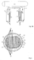
- FIG. 3 the formation of cooling channels 27 in a tunnel arrangement on a thin tube plate 28 of the secondary quench cooler 20 is shown in section just above the tube sheet.
- the cooling channels 27 are arranged in parallel as a tunnel.
- the cooling channels 27 are provided on the surface formed by a cover plate 34 perpendicular to the tube sheet 28 with openings 18 which are arranged at a predetermined distance.
- Fig. 3 combined with Fig. 4, 4B and Fig. 5 can be better seen, are passed through the openings 18 perpendicular to the tube sheet 28 at a distance from each other bundle tubes 29 of tube bundles with an opening formed between the opening and bundle tube annular gap 19, which is predetermined between the respective opening 18 and the bundle tube 29.
- the one ends of the bundle tubes 29 are welded to the thin tube sheet 28, and the opposite ends of the bundle tubes are welded to the tube bottom, not shown, on the opposite side of the quench cooler 20, not shown.
- the medium of the water / steam mass flow flows according to Fig. 4B via the secondary feed pipe 44, not shown, to the cooling water inlet 25, not shown, of the secondary quench cooler 20.
- the mass flow is conducted by means of a deflecting plate 43 adapted to the outer circumference of the arranged cooling channels 27 to inlet openings 30 of the cooling channels 27 formed in tunnel arrangement.
- the entire mass flow is divided into the individual tunnels or cooling channels 27 and passes from the Inlet openings 30 under flow around and thus cooling the perpendicular to the cooling channels with spaced apart plugged bundle tubes 29 all tunnels or cooling channels in the direction of outlet openings 31 which are arranged at a distance from the inlet openings 30 aligned. This results in a clearly directed flow from the inlet openings 30 to the outlet openings 31.
- annular gaps 19 are preferably provided so that an intensive cooling of the bundle tubes 29 in the region of the annular gaps can take place, because a part of the mass flow passes through the annular gaps 19 and an effective heat dissipation is achieved.
- Fig. 4A shows a section along the line A - A after Fig. 3 and Fig. 4B shows a section along the line B - B after Fig. 3 ,
- Fig. 4A are the on the thin tube sheet 28 separated by webs 33 and parallel cooling channels 27 or tunnel clearly visible through the cover 34th covered and separated by webs 33 from each other, wherein for the sake of clarity, the plugged through the openings 18 bundle tubes 29 are omitted.
- the cooling channels 27 are arranged in parallel on the tube plate 28, which is connected to the annular flange 35, which is welded to the jacket 32 of the quench cooler 20.
- the cooling channels 27 in tunnel arrangement are in the water / steam region of the jacket 32 enclosed by the enclosed tube bundle shell space 36.
- the tube sheet 28 with the cooling channels 27 mounted thereon in tunnel arrangement is on the side of the gas inlet 21 or the gas outlet 23 according to the arrow depending on the circuit according to Fig. 2A or Fig. 2B the quench cooling system arranged.
- Fig. 4B is a cooling channel 27 or tunnel with the cover plate 34 shown, the inlet opening 30 is greater than the outlet opening 31.
- the cooling channel 27 is disposed on the thin tube sheet 28 which is connected to the annular flange 35.
- the annular flange 35 is welded to the jacket 32 of the quench cooler 20, which surrounds the jacket space 36.
- the deflection plate 43 is arranged on the tube plate 28 to form a water chamber 46, which is adapted to the outer circumference of the cooling channels and divides the water / steam mass flow to the individual cooling channels 27.
- the in Fig. 4B shown cooling channel 27 in the tunnel arrangement has a change in the cross section of the tunnel by a continuous reduction of the tunnel height from the inlet opening 30 to the outlet opening 31.
- the continuous reduction of the tunnel height between the vertical line of the outlet opening and the cover plate is determined by an angle ⁇ .
- the predetermined angle is dependent on the required increase in speed the flow over predetermined areas of the tube sheet and is in the range of greater than or equal to 90 ° to 110 °.
- Fig. 5 shows a detail X after 4A , wherein the cooling channels 27 formed by the parallel webs 33 and the cover plate 34 with the openings 18 for inserted bundled tubes 29 including the annular gaps 19 in tunnel arrangement in conjunction with the tube sheet 28 can be clearly seen.
- cooling channels 27 Surrounding the arranged on the thin tube plate 28 cooling channels 27 in tunneling arrangement of the annular flange 35 which is connected to the tube plate and the jacket 32 of the quench cooler 20.
- the tunnel arrangement In the case of vertically arranged secondary quench coolers 20, the tunnel arrangement is always installed on the water / steam side at the lowest points of the quench cooler. It is not important whether it is the gas inlet or the gas outlet. In the case of horizontally arranged secondary quench coolers 20, the tunnel arrangement is mounted on the side of the gas inlet 21 on the water / steam side.
- the webs 33 which separate the individual water / vapor streams from each other, so that a clearly directed flow from the inlet openings 30 in the direction of Outlet openings 31 of the cooling channels 27 or tunnel can be achieved, wherein the webs are connected to the tube plate 28.
- the cover plate 34 which ensures a limitation of the flow in the tunnel arrangement of the cooling channels 27 and substantially prevents escape of the flow to the intended proportion, which passes through the annular gaps 19, in a jacket space 32 enclosed by the jacket space 36, the bundle tubes 29th of the tube bundle.
- the cover plate 34 is connected to the webs 33, in particular welded.
- FIG. 6 is the representation of a cooling channel 27 in tunnel arrangement according to Fig. 4B shown with the flow of the cooling medium.
- the annular flange 35 is clearly visible, which is connected to the tube plate 28 on which the cooling channels 27 are mounted in a tunnel arrangement.
- the annular flange 35 is connected to the jacket 32 of the quench cooler 20, not shown, wherein the jacket space 36 is formed, which encloses the bundle tubes, not shown, of the tube bundle and includes a water / steam region.
- the cooling medium passes according to the arrow direction at the cooling water inlet 25 in the inlet chamber 46, which extends over one half of the circumference of the shell 32 and is essentially bounded by the baffle 43, with the tube sheet 28 along the inlet openings 30 of the cooling channels 27 and is therefore connected to the jacket 32 just above the cooling water inlet, preferably welded. From the inlet chamber 46, the cooling medium reaches the individual inlet openings 30 of the cooling channels 27 and leaves the cooling channels at the outlet openings 31 and enters the shell space 36. Furthermore, indicated by arrows that the tube plate 28 on the side of the gas inlet 21 or the gas outlet 23rd can be arranged depending on the circuit of the quench cooler.
- the predetermined reduction of the cross section from the inlet opening 30 to the outlet opening 31 of the cooling channel 27 or tunnel is intended to increase the flow velocity of the water / steam mass flow.
- the increase in the flow rate of the mass flow associated with the reduction of the cross section is primarily important for more intensive cooling of heavily loaded parts of the tube bottom 28, especially the middle of the tube plate, for a longer service life of the quench cooler 20 and thus of the quench cooling system.
- the special design of the cooling channels 27 in a tunnel arrangement is required to preclude that form deposits on the inner side or water side of the tube plate 28.
- the directed flow has to have a defined speed over the tubesheet. Therefore, while maintaining the mass flow in the tunnels, adjust the required speed under the change in the cross section of the tunnels.
- the change in the cross section of the tunnels is achieved by a continuous reduction of the tunnel height.
- Fig. 7 is a similar representation as in Fig. 3 shown, wherein in each case the inlet openings 30 and outlet openings 31 of the tunnels designed in tunnel arrangement 27 each inspection or cleaning nozzle 37 are assigned, which are mounted on the shell side opposite to the annular flange 35 in alignment.
- the inspection or cleaning nozzle 37 are each provided with a cap 38 which are removably mounted in the region of the tunnel assembly in the case of a water-side maintenance or inspection of the bundle tubes 29.
- the caps or only individual caps 38 can be removed at the inspection or cleaning nozzle 37, which are opposite each other.
- the separably arranged caps 38 of the inspection or cleaning nozzle 37 are provided as an opening or access for inspection or for cleaning the tunnel arrangement of the cooling channels 27.
- the caps 38 of the respectively opposite inspection or cleaning nozzle 37 are removed.
- a measuring device 37 any deposits can be detected at the removed caps 38 through the inspection or cleaning nozzle 37.
- the deposits to be removed with a high-pressure water jet are supplied to a blowdown collector 39 which is mounted on one side of the inspection or cleaning nozzles 37 and receives and discharges the blowdown water.
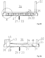
- Fig. 8 is the detail Y in an enlarged scale according to Fig. 7 shown.
- the Abschlämmsammler 39 for receiving the Abschlämmwassers on one side is connected to drain pipes 41.
- the drain pipes 41 are welded to the annular flange 35 at the level of the tunnel arrangement of the cooling channels 27, not shown, and formed via holes 42 in the annular flange 35 as accesses to the tunnel arrangement of the cooling channels.
- the inspection or cleaning nozzles 37 with the caps 38 are arranged on the other side of the Abschlämmsammlers 39, which lie opposite the drain pipes 41.
- Fig. 9 shows a detail Z on an enlarged scale according to Fig. 7 .
- the inspection or cleaning nozzles 37 are attached directly to the annular flange 35, parallel and aligned with the direction of the one on the side opposite the arrangement of the blowdown collector 39 Fig. 8 arranged inspection or cleaning nozzle.
- the inspection or cleaning nozzles 37 each provide access to the tunnel arrangement of the cooling channels 27 for inspection or cleaning of the cooling channels or tunnels.
Description
Die Erfindung betrifft ein Quenchkühlsystem mit den Merkmalen des Oberbegriffs des Patentanspruchs 1.The invention relates to a quench cooling system having the features of the preamble of patent claim 1.
Bei einigen Anlagen zur Äthylenherstellung werden Spaltgasöfen oder Cracking Furnaces in einem zweistufigen Kühlsystem verwendet. Dabei wird gewöhnlich ein vertikal angeordneter Doppelrohrwärmetauscher als primärer Quenchkühler und ein herkömmlicher vertikal oder horizontal angeordneter Rohrbündel-Wärmetauscher als sekundärer Quenchkühler vorgesehen.In some ethylene production plants, fission gas furnaces or cracking furnaces are used in a two-stage cooling system. In this case, usually a vertically arranged double tube heat exchanger is provided as a primary quench cooler and a conventional vertically or horizontally arranged tube bundle heat exchanger as a secondary quench cooler.
Ein solcher Rohrbündel-Wärmetauscher dient als Prozessgas-Abhitzekessel zur schnellen Abkühlung von Reaktionsgasen aus Spaltgasöfen oder Chemieanlagen-Reaktoren bei gleichzeitiger Erzeugung von Hochdruckdampf als die entstehende Wärme abführendes Kühlmedium.Such a tube bundle heat exchanger serves as a process gas waste heat boiler for rapid cooling of reaction gases from Spaltgasöfen or chemical plant reactors with simultaneous generation of high pressure steam as the heat dissipating cooling medium.
Aus der
Aus der
Typische Anordnungen solcher Quenchkühlsysteme sind in
Die Anordnungen der beiden unterschiedlichen primären und sekundären Quenchkühler, die einer gemeinsamen, erhöht angeordneten Dampftrommel dienen, sind die bevorzugten Ausführungen in Verbindung mit der Brennkammer eines Spaltgasofens. In den meisten Fällen werden die Quenchkühler oberhalb des Strahlungsteils des Spaltgasofens angeordnet.
Bei vertikal angeordneten sekundären Quenchkühlern, bei denen der Rohrboden beim Gaseintritt nach
Kleine feste Partikel treten sehr oft in das Wasser des Wasserkreislaufes des Quenchkühlers ein, insbesondere während der Inbetriebnahme einer solchen Anlage, wie zum Beispiel für die Äthylenherstellung. Zusätzlich erzeugen die wasserseitigen Metalloberflächen des Rohrbodens, der Rohre und des Mantels eine Schicht aus Magnetit oder Fe3O4. Die Schicht aus Magnetit schützt den Stahl des Rohrbodens und erneuert sich stetig langsam selbst aus der Metalloberfläche bei Betriebstemperatur, wobei eine kleine Menge von Partikeln bestehend aus Magnetit in das Wasser freigesetzt wird.Typical arrangements of such quench cooling systems are in
The arrangements of the two different primary and secondary quench coolers which serve a common, elevated steam drum are the preferred embodiments in connection with the combustion chamber of a fission gas furnace. In most cases, the quench coolers are arranged above the radiation part of the fission gas furnace.
For vertically arranged secondary quench coolers in which the tube bottom after gas entry
Small solid particles are very often in the water of the water cycle of the quench cooler, especially during commissioning of such a system, such as for Äthylenherstellung. In addition, the generate water-side metal surfaces of the tubesheet, the tubes and the jacket a layer of magnetite or Fe 3 O 4 . The layer of magnetite protects the steel of the tubesheet and continuously renews itself from the metal surface at operating temperature, releasing a small amount of particles of magnetite into the water.
Neben der hohen Geschwindigkeit des Wasserflusses ist ebenso wichtig, den Wasserfluss über den Rohrboden weg von empfindlichen Bereichen des Rohrbodens, z. B. die Rohrbodenmitte mit dem höchsten Wärmefluss, zu Stellen zu führen, an denen ein wirksames Umwehen oder Blow-Down angewendet werden kann.In addition to the high speed of the water flow is just as important, the flow of water through the tube bottom away from sensitive areas of the tube sheet, z. As the tube bottom center with the highest heat flux, to lead to places where an effective blow or blow-down can be applied.
Das Rohrbodendesign des sekundären Quenchkühlers ist als sogenanntes Membrandesign ausgebildet und besteht aus einer dünnen Platte mit einer Stärke von ungefähr 25 mm. Die Bündelrohre des Quenchkühlers werden auf die dünne Platte geschweißt.The tube bottom design of the secondary quench cooler is designed as a so-called membrane design and consists of a thin plate with a thickness of about 25 mm. The bundle tubes of the quench cooler are welded onto the thin plate.
Es sind keine Vorrichtungen auf der Platte vorgesehen, um den Wasserfluss über den Rohrboden des Gaseintritts oder des Gasaustritts zu führen.There are no devices on the plate provided to guide the flow of water through the tube bottom of the gas inlet or the gas outlet.
Eine Aufgabe der vorliegenden Erfindung besteht darin, ein Quenchkühlsystem mit einer Mediumflussanordnung zu schaffen, bei welcher der Mediumfluss je nach Schaltung des sekundären Quenchkühlers über den Rohrboden der Gaseintrittsseite oder der Gasaustrittsseite so geführt ist, dass Ablagerungen verhindert werden. Eine weitere Aufgabe besteht darin, zu der Mediumflussanordnung auf dem Rohrboden auf Seiten des Gaseintritts oder des Gasaustritts einen Zugriff vorzusehen, durch den der Rohrboden inspiziert und abhängig von der Inspektion auf einfache Weise gereinigt werden kann.An object of the present invention is to provide a quench cooling system with a medium flow arrangement in which the medium flow is guided over the tube bottom of the gas inlet side or the gas outlet side depending on the circuit of the secondary quench cooler so that deposits are prevented. A further object is to provide an access to the medium flow arrangement on the tubesheet on the gas inlet or gas outlet side through which the tubesheet can be inspected and easily cleaned depending on the inspection.
Die zugrundeliegende Aufgabe wird gelöst durch ein Quenchkühlsystem mit einem primären Quenchkühler als Doppelrohrwärmetauscher und einem Rohrbündelwärmetauscher als sekundären Quenchkühler mit mindestens einem Rohrbündel, wobei das Rohrbündel von einem Mantel unter Bildung eines Mantelraumes umschlossen ist, der zwischen zwei mit Abstand voneinander angeordneten Rohrböden ausgebildet ist, zwischen denen Bündelrohre des Rohrbündels beidseitig in den Rohrböden gehalten sind. Dabei ist der Rohrboden auf der Seite vom Gaseintritt oder Gasaustritt mit den Bündelrohren als dünner Rohrboden in Membrandesign ausgebildet. Der dünne Rohrboden ist mit parallelen Kühlkanälen versehen, die miteinander in Verbindung stehen und von einem Kühlmedium durchströmt sind. Die Kühlkanäle sind in Tunnelanordnung ausgebildet und auf dem dünnen Rohrboden als Rohrplatte angeordnet. Die Kühlkanäle in Tunnelanordnung weisen eine viereckige Tunnelgeometrie auf. Die Kühlkanäle mit Tunnelgeometrie sind gebildet aus dem dünnen Rohrboden, der eine Gasseite von einer Wasser-/Dampfseite trennt und mit einem Ringflansch verbunden ist, der mit dem Mantel des umschlossenen Rohrbündels verbunden ist; aus auf dem Rohrboden angeordneten parallelen Stegen, die mit dem Rohrboden verbunden sind und einzelne Wasser-/Dampfströme voneinander trennen; aus einem mit Öffnungen für Bündelrohre versehenen Abdeckblech, das mit den Stegen verbunden ist und die Strömung in der Tunnelanordnung der Kühlkanäle begrenzt und ein Entweichen der Strömung in einen vom Mantel des eingeschlossenen Rohrbündels umschlossenen Mantelraum bis auf einen vorbestimmten Anteil verschließt. Die in Tunnelanordnung ausgebildeten Kühlkanäle bewerkstelligen eine eindeutig gerichtete Strömung von den Eintrittsöffnungen in Richtung der Austrittsöffnungen der Kühlkanäle.The underlying object is achieved by a quench cooling system with a primary quench cooler as Double tube heat exchanger and a tube bundle heat exchanger as a secondary quench cooler with at least one tube bundle, wherein the tube bundle is enclosed by a jacket to form a jacket space formed between two spaced apart tube plates, between which bundle tubes of the tube bundle are held on both sides in the tube sheets. In this case, the tube plate is formed on the side of the gas inlet or gas outlet with the bundle tubes as a thin tube plate in membrane design. The thin tubesheet is provided with parallel cooling channels, which communicate with each other and are flowed through by a cooling medium. The cooling channels are formed in a tunnel arrangement and arranged on the thin tubesheet as a tube plate. The cooling channels in tunnel arrangement have a quadrangular tunnel geometry. The cooling channels with tunnel geometry are formed from the thin tubesheet, which separates a gas side from a water / steam side and is connected to an annular flange which is connected to the shell of the enclosed tube bundle; from arranged on the tube bottom parallel webs, which are connected to the tubesheet and separate individual water / vapor streams from each other; a cover plate provided with openings for bundle tubes, which is connected to the webs and limits the flow in the tunnel arrangement of the cooling channels and closes an escape of the flow in a jacket space enclosed by the shell of the enclosed tube bundle to a predetermined proportion. The cooling channels formed in the tunnel arrangement accomplish a clearly directed flow from the inlet openings in the direction of the outlet openings of the cooling channels.
Als besonders vorteilhaft hat sich herausgestellt, wenn mindestens zwei der jeweiligen Kühlkanäle in Tunnelanordnung eine Veränderung des Querschnitts der Kühlkanäle oder der Tunnel durch eine kontinuierliche Reduzierung der Tunnelhöhe von der Eintrittsöffnung zur Austrittsöffnung um einen vorbestimmten Winkel α aufweisen, der zwischen der senkrechten Linie der Austrittsöffnung und dem Abdeckblech gebildet ist.It has proven to be particularly advantageous if at least two of the respective cooling ducts in tunnel arrangement have a change in the cross section of the cooling ducts or the tunnels by a continuous reduction of the tunnel height from the inlet opening to the outlet opening by a predetermined angle .alpha vertical line of the outlet opening and the cover plate is formed.
Weiterhin hat sich als vorteilhaft erwiesen, wenn der zwischen der senkrechten Linie der Austrittsöffnung eines Kühlkanals und dem Abdeckblech gebildete vorbestimmte Winkel α im Bereich von größer/gleich 90° bis 110° liegt, da der Winkel abhängig ist von der vorbestimmten Erhöhung der erforderlichen Geschwindigkeit der Strömung über vorbestimmte Bereiche des zu kühlenden Rohrbodens.Furthermore, it has proved to be advantageous if the formed between the vertical line of the outlet opening of a cooling duct and the cover plate predetermined angle α in the range of greater than / equal to 90 ° to 110 °, since the angle is dependent on the predetermined increase in the required speed Flow over predetermined areas of the tube bottom to be cooled.
Als weiteren Vorteil bei einer anderen Ausbildung des erfindungsgemäßen Quenchkühlsystems hat zu gelten, dass auf Höhe der Kühlkanäle in Tunnelanordnung an der äußeren Oberflächenseite des mit dem Mantel verbundenen Ringflansches jeweils gegenüberliegend und fluchtend Inspektions- oder Reinigungsstutzen angebracht sind und dass die Inspektions- oder Reinigungsstutzen über Bohrungen im Ringflansch mit den Kühlkanälen in Tunnelanordnung kommunizieren.As a further advantage of another embodiment of the quench cooling system according to the invention has to be considered that at the level of the cooling channels in tunnel arrangement on the outer surface side of the jacket connected to the annular flange each opposite and aligned inspection or cleaning nozzle are mounted and that the inspection or cleaning nozzle via holes communicate in the annular flange with the cooling channels in tunnel arrangement.
Weiter ist als vorteilhaft festgestellt worden, wenn die den Kühlkanälen zugeordneten und jeweils gegenüberliegend und fluchtend am Ringflansch angebrachten Inspektions- oder Reinigungsstutzen mit Kappen ausgerüstet sind und wenn die Kappen oder einzelne Kappen der jeweils gegenüberliegenden Inspektions- oder Reinigungsstutzen als Öffnung zur wasserseitigen Wartung oder Inspektion der Bündelrohre im Bereich der Kühlkanäle in Tunnelanordnung entfernbar angebracht sind.Next has been found to be advantageous if the cooling channels assigned and each opposite and aligned on the annular flange mounted inspection or cleaning nozzle are equipped with caps and if the caps or caps of each opposite inspection or cleaning nozzle as an opening for water-side maintenance or inspection of the Bundle tubes in the region of the cooling channels in the tunnel assembly are removably mounted.
Bei dem erfindungsgemäßen Quenchkühlsystem hat sich weiter als vorteilhaft erwiesen, dass die Kappen oder einzelne Kappen der jeweils gegenüberliegenden Inspektions- oder Reinigungsstutzen als Öffnung zur Reinigung von vorhandenen Ablagerungen im Bereich der Kühlkanäle in Tunnelanordnung mit einem Wasserstrahl entfernbar angebracht sind.In the quench cooling system according to the invention has proved to be further advantageous that the caps or individual caps of the respective opposite inspection or cleaning nozzle as an opening for cleaning of existing deposits in the region of the cooling channels in tunnel arrangement are removably attached with a water jet.
Bei einer weiteren Ausbildung des erfindungsgemäßen Quenchkühlsystems hat sich als vorteilhaft herausgestellt, dass die den Kühlkanälen zugeordneten und jeweils gegenüberliegend und fluchtend am Ringflansch angebrachten Inspektions- oder Reinigungsstutzen über die Bohrungen im Ringflansch und über als Weiterführung der Bohrungen an dem Ringflansch angeschweißte Ablaufrohre mit einem an einer Seite auf Höhe der Kühlkanäle in Tunnelanordnung angebrachten Abschlämmsammler kommunizieren.In a further embodiment of the quench cooling system according to the invention has been found to be advantageous that the cooling channels associated and each opposite and flush mounted on the annular flange inspection or cleaning nozzle on the holes in the annular flange and as a continuation of the holes on the annular flange welded drain pipes with a on a Side communicating at the height of the cooling ducts in the tunnel arrangement Ablähmmsammler communicate.
Weiter ist besonders vorteilhaft, dass die Inspektions- oder Reinigungsstutzen an der den Ablaufrohren gegenüberliegenden Außenseite des Abschlämmsammlers angeordnet sind.It is also particularly advantageous that the inspection or cleaning nozzles are arranged on the outside of the Abschlämmsammlers opposite the outlet pipes.
Bei der Ausbildung des Quenchkühlsystems mit dem Abschlämmsammler ist vorteilhaft, dass die Inspektions- öder Reinigungsstutzen gegenüber der Seite mit der Anordnung des Abschlämmsammlers direkt am Ringflansch angeordnet sind.When forming the quench cooling system with the blowdown collector, it is advantageous for the inspection holes or cleaning nozzles to be arranged directly on the ring flange relative to the side with the arrangement of the blowdown collector.
Das bevorzugte Tunnelflussdesign sichert eine hohe Mediumflussgeschwindigkeit über den Rohrboden der Gaseintrittsseite oder der Gasaustrittsseite. Wegen der hohen Geschwindigkeit des Mediumflusses können sich grundsätzlich nicht irgendwelche festen Partikel auf dem Rohrboden absetzen. Da ein Absetzen von festen Partikeln auf dem Rohrboden im wesentlichen nicht eintritt, können eine Überhitzung des Rohrbodens und eine Heißwasserkorrosion nicht eintreten.The preferred tunnel flow design ensures a high fluid flow rate over the tube bottom of the gas inlet side or the gas outlet side. Because of the high speed of the medium flow, basically no solid particles can settle on the tubesheet. Since settling of solid particles on the tubesheet does not substantially occur, overheating of the tubesheet and hot water corrosion can not occur.
Die Tunnelflussanordnung weist zwei entscheidende Merkmale auf. Erstens setzen sich feste Partikel aufgrund der erzeugten hohen Mediumflussgeschwindigkeit durch die vorteilhafte Tunnelflussanordnung im wesentlichen nicht ab, und zweitens tritt eine Überhitzung des Rohrbodens durch eine vorgesehene geführte intensive Kühlung und somit eine Heißwasserkorrosion nicht ein. Die Tunnelflussanordnung stellt einen kontinuierlichen und gleichförmigen Wasserfluss zu und entlang dem Rohrboden der Gaseintrittsseite oder der Gasaustrittsseite eines vertikal angeordneten sekundären Quenchkühlers sicher, wobei im wesentlichen eine Ablagerung von festen Partikeln und Schlamm auf der Wasserseite verhindert wird.The tunnel flow arrangement has two crucial features. Firstly, due to the high medium flow velocity generated, solid particles essentially do not settle due to the advantageous tunnel flow arrangement, and secondly, an overheating of the tube bottom occurs due to an intended guided intensive cooling and thus a Hot water corrosion not a. The tunneling flow arrangement ensures a continuous and uniform flow of water to and along the tube bottom of the gas entrance side or the gas exit side of a vertically arranged secondary quench cooler, substantially preventing deposition of solid particles and sludge on the water side.
Auf eine solche Weise wird die Laufzeit und Zuverlässigkeit eines Quenchkühlsystems durch die Ausbildung der vorteilhaften Tunnelflussanordnung auf dem jeweiligen Rohrboden beträchtlich gesteigert.In such a way, the running time and reliability of a quench cooling system is considerably increased by the formation of the advantageous tunnel flow arrangement on the respective tubesheet.
In weiterer Ausbildung des erfindungsgemäßen Quenchkühlsystems ist in vorteilhafter Weise vorgesehen, dass über die Inspektions- und Reinigungsstutzen bei entfernten Kappen ein durchgehender Zugriff auf jeden auf dem Rohrboden angeordneten Kühlkanal zu erreichen ist, der dann durch Einleiten von Wasser als bevorzugtes Medium unter Hochdruck entweder von beiden Seiten oder von nur einer Seite zu reinigen ist. Das Abschlämmwasser verlässt den Kühlkanal jeweils auf der gegenüberliegenden Seite, bevorzugter Weise über Ablaufrohre in den angebrachten Abschlämmsammler.In a further embodiment of the quench cooling system according to the invention is provided in an advantageous manner that on the inspection and cleaning nozzle with remote caps continuous access to each arranged on the tubesheet cooling channel is reached, which then by introducing water as a preferred medium under high pressure either of two Pages or from just one page to clean. The Abschlämmwasser leaves the cooling channel respectively on the opposite side, preferably via drain pipes in the attached Abschlämmsammler.
Weitere Vorteile der Erfindung sind in der Zeichnung anhand von Ausführungsbeispielen dargestellt und nachfolgend näher beschrieben. Es zeigen:
-
Fig. 1 ein Quenchkühlsystem mit einem primären Quenchkühler in vertikaler Anordnung und einem sekundären Quenchkühler in horizontaler Anordnung gemäß dem Stand der Technik; -
Fig. 2A eine ähnliche Anordnung wie inFig. 1 mit einem primären Quenchkühler in vertikaler Anordnung und einem sekundären Quenchkühler in einer vertikalen Aufstellung mit einem am unteren Ende angebrachten Gaseintritt gemäß dem Stand der Technik; -
Fig. 2B eine ähnliche Anordnung wie inFig. 2A mit einem am oberen Ende angeordneten Gaseintritt beim sekundären Quenchkühler in einer vertikalen Aufstellung gemäß dem Stand der Technik; -
Fig. 3 ein erfindungsgemäßes Quenchkühlsystem mit einer Ausführung von Kühlkanälen in Tunnelanordnung auf einem dünnen Rohrboden eines sekundären Quenchkühlers im Schnitt kurz über dem Rohrboden in verkleinertem Maßstab in Draufsicht; -
Fig. 4A ein erfindungsgemäßes Quenchkühlsystem mit einer Ausführung von Kühlkanälen in Tunnelanordnung nachFig. 3 im Schnitt entlang der Linie A - A; -
Fig. 4B ein erfindungsgemäßes Quenchkühlsystem mit einer Ausführung eines Kühlkanals in Tunnelanordnung nachFig.3 im Schnitt entlang der Linie B - B; -
Fig. 5 eine Einzelheit X nachFig. 4A im vergrößerten Maßstab; -
Fig. 6 eine Ausbildung eines Kühlkanals oder Tunnels zur Erhöhung der Mediumflussgeschwindigkeit über einen Rohrboden eines sekundären Quenchkühlers für das erfindungsgemäße Quenchkühlsystem gemäßFig.4B mit Kühlwassereintritt; -
Fig. 7 eine Ausführung für einen Zugang zu angeordneten Kühlkanälen in Tunnelanordnung auf einem dünnen Rohrboden. eines sekundären Quenchkühlers des erfindungsgemäßen Quenchkühlsystems im Schnitt gemäßFig. 3 ; -
Fig 8 eine Einzelheit Y nachFig. 7 in einem vergrößerten Maßstab und -
Fig. 9 eine Einzelheit Z nachFig. 7 in einem vergrößerten Maßstab.
-
Fig. 1 a quench cooling system with a primary quench cooler in a vertical arrangement and a secondary quench cooler in a horizontal arrangement according to the prior art; -
Fig. 2A a similar arrangement as inFig. 1 with a primary quench cooler in a vertical arrangement and a secondary quench cooler in a vertical setup with a bottom-mounted gas inlet according to the prior art; -
Fig. 2B a similar arrangement as inFig. 2A with a gas inlet arranged at the upper end of the secondary quench cooler in a vertical installation according to the prior art; -
Fig. 3 a quench cooling system according to the invention with a design of cooling ducts in tunnel arrangement on a thin tube plate of a secondary quench cooler in section just above the tubesheet on a reduced scale in plan view; -
Fig. 4A an inventive Quenchkühlsystem with an execution of cooling ducts in tunnel arrangement afterFig. 3 in section along the line A - A; -
Fig. 4B a quench cooling system according to the invention with an embodiment of a cooling duct in tunnel arrangement according toFigure 3 in section along the line B - B; -
Fig. 5 a detail X afterFig. 4A on an enlarged scale; -
Fig. 6 an embodiment of a cooling channel or tunnel for increasing the medium flow rate over a tube plate of a secondary quench cooler for the quench cooling system according to the invention according to4B with cooling water inlet; -
Fig. 7 an embodiment for access to arranged cooling channels in tunnel arrangement on a thin tube sheet. a secondary quench cooler of the quench cooling system according to the invention in section according toFig. 3 ; -
Fig. 8 a detail Y afterFig. 7 on an enlarged scale and -
Fig. 9 a detail Z afterFig. 7 on an enlarged scale.
Das in
Ein Gaseinlass 11 für einen Gasstrom gemäß Pfeilrichtung ist am unteren Ende des vertikal aufgestellten primären Quenchkühlers 10 angeordnet. Der Gasstrom verlässt am oberen Ende beim Gasauslass 12 den vertikal aufgestellten primären Quenchkühler 10 in einem vorbestimmten abgekühlten Zustand. Der abgekühlte Gasstrom wird über eine zwischen dem Gasauslass 12 des primären Quenchkühlers 10 und einem Gaseintritt 21 eines Eintrittskopfes 22 des horizontal angeordneten sekundären Quenchkühlers 20 angebrachte Rohrleitung 17 dem sekundären Quenchkühler 20 auf der Seite des Gaseintritts zugeführt, um weiter heruntergekühlt zu werden, und verlässt den sekundären Quenchkühler 20 auf der gegenüberliegenden Seite beim Gasaustritt 23 eines Austrittskopfes 24.A
Das Kühlmedium, insbesondere Wasser, wird dem primären Quenchkühler 10 aus der Dampftrommel 40 gemäß Pfeilrichtung über eine Zulaufrohrleitung 15 oberhalb des Gaseinlasses 11 beim Kühlwassereinlass 13 zugeführt und verlässt als Wasser-/Dampfgemisch den Quenchkühler über eine Abführrohrleitung 16 unterhalb des Gasauslasses 12 beim Kühlwasserauslass 14 zurück in die Dampftrommel 40. Dem horizontal angeordneten sekundären Quenchkühler 20 wird das Kühlmedium gemäß Pfeilrichtung über eine sekundäre Zulaufrohrleitung 44 hinter dem Eintrittskopf 22 beim Kühlwassereintritt 25 aus der Dampftrommel 40 zugeführt und verlässt als Wasser-/ Dampfgemisch den Quenchkühler vor dem Austrittskopf 24 über einen Kühlwasseraustritt 26 und eine sekundäre Abführrohrleitung 45 zurück zur Dampftrommel.The cooling medium, in particular water, is fed to the primary quench cooler 10 from the
Solche Quenchkühlsysteme dienen zum schnellen Kühlen von Reaktionsgas oder Spaltgas aus einem Spaltgasofen oder einem Chemieanlagen-Reaktor mit Hilfe von einem unter Hochdruck stehenden, siedenden und teilweise verdampfenden Medium, insbesondere Wasser.Such quench cooling systems are used for the rapid cooling of reaction gas or fission gas from a fission gas furnace or a chemical plant reactor with the aid of a pressurized, boiling and partially vaporizing medium, in particular water.
In
Das Kühlmedium, insbesondere Wasser, aus der Dampftrommel 40 wird in
In
Bei der in
In
Wie aus
Das Medium des Wasser-/Dampf-Massenstroms strömt gemäß
Bei der Durchströmung der Tunnel oder Kühlkanäle 27 dringt ein kleiner Teil des Massenstroms gemäß
Hinter den Austrittsöffnungen 31 nach
In
In
Der in
Die Tunnelanordnung wird bei vertikal angeordneten sekundären Quenchkühlern 20 wasser-/dampfseitig immer an den am tiefsten liegenden Stellen des Quenchkühlers angebracht. Dabei ist es nicht wichtig, ob es sich um den Gaseintritt oder den Gasaustritt handelt. Bei horizontal angeordneten sekundären Quenchkühlern 20 ist die Tunnelanordnung wasser-/dampfseitig an der Seite des Gaseintritts 21 angebracht.In the case of vertically arranged secondary quench
Die gesamte Tunnelanordnung der Kühlkanäle 27 oder Tunnel ist von dem Ringflansch 35 umgeben. Eine bevorzugte viereckige Tunnelgeometrie ist im wesentlichen durch drei Bauteile gebildet:
- Der dünne Rohrboden 28, der die Gasseite von der Wasser-/Dampfseite trennt und
mit dem Ringflansch 35 verbunden ist.
- The
thin tube sheet 28, which separates the gas side from the water / steam side and is connected to theannular flange 35.
Die Stege 33, welche die einzelnen Wasser-/Dampfströme voneinander trennen, so dass eine eindeutig gerichtete Strömung von den Eintrittsöffnungen 30 in Richtung der Austrittsöffnungen 31 der Kühlkanäle 27 oder Tunnel erzielbar ist, wobei die Stege mit dem Rohrboden 28 verbunden sind.The
Das Abdeckblech 34, das eine Begrenzung der Strömung in der Tunnelanordnung der Kühlkanäle 27 sicherstellt und im wesentlichen ein Entweichen der Strömung bis auf den vorgesehenen Anteil, der durch die Ringspalte 19 hindurchtritt, in einen vom Mantel 32 umschlossenen Mantelraum 36 verhindert, der die Bündelrohre 29 des Rohrbündels einschließt. Das Abdeckblech 34 ist mit den Stegen 33 verbunden, insbesondere verschweißt.The
Mit der Ausbildung der Kühlkanäle 27 in Tunnelanordnung ist eine eindeutig gerichtete Strömung von den Eintrittsöffnungen 30 in Richtung der Austrittsöffnungen 31 der Kühlkanäle 27 sichergestellt.With the formation of the
In
Das Kühlmedium gelangt gemäß Pfeilrichtung beim Kühlwassereintritt 25 in die Eintrittskammer 46, die sich über eine Hälfte des Umfangs des Mantels 32 erstreckt und im wesentlichen vom Umlenkblech 43 begrenzt ist, das mit dem Rohrboden 28 entlang den Eintrittsöffnungen 30 der Kühlkanäle 27 und dementsprechend mit dem Mantel 32 kurz oberhalb des Kühlwassereintritts verbunden ist, vorzugsweise verschweißt ist. Aus der Eintrittskammer 46 gelangt das Kühlmedium zu den einzelnen Eintrittsöffnungen 30 der Kühlkanäle 27 und verlässt die Kühlkanäle bei den Austrittsöffnungen 31 und gelangt in den Mantelraum 36. Weiterhin ist durch Pfeile angedeutet, dass der Rohrboden 28 auf der Seite des Gaseintritts 21 oder des Gasaustritts 23 je nach Schaltung des Quenchkühlers angeordnet sein kann.The cooling medium passes according to the arrow direction at the cooling
Die vorbestimmte Reduzierung des Querschnitts von der Eintrittsöffnung 30 zur Austrittsöffnung 31 des Kühlkanals 27 oder Tunnels ist für eine Erhöhung der Flussgeschwindigkeit des Wasser-/Dampf-Massenstroms vorgesehen. Die mit der Reduzierung des Querschnitts verbundene Erhöhung der Flussgeschwindigkeit des Massenstroms ist zur intensiveren Kühlung von stark belasteten Teilen des Rohrbodens 28, vor allem der Mitte des Rohrbodens, für eine längere Standzeit des Quenchkühlers 20 und damit des Quenchkühlsystems vorrangig wesentlich.The predetermined reduction of the cross section from the inlet opening 30 to the outlet opening 31 of the cooling
Die besondere Ausbildung der Kühlkanäle 27 in Tunnelanordnung ist erforderlich, um auszuschließen, dass sich Ablagerungen an der inneren Seite oder Wasserseite des Rohrbodens 28 bilden. Zur Verhinderung von Ablagerungen hat die gerichtete Strömung über den Rohrboden eine definierte Geschwindigkeit aufzuweisen. Daher ist unter Beibehaltung des Massenstroms in den Tunneln die erforderliche Geschwindigkeit unter der Veränderung des Querschnitts der Tunnel anzupassen. Die Veränderung des Querschnitts der Tunnel wird durch eine kontinuierliche Reduzierung der Tunnelhöhe erreicht.The special design of the
In
Die abtrennbar angeordneten Kappen 38 der Inspektions- oder Reinigungsstutzen 37 sind als Öffnung oder Zugriff zur Inspektion oder zum Reinigen der Tunnelanordnung der Kühlkanäle 27 vorgesehen. Zur Inspektion oder zum Reinigen werden die Kappen 38 der sich jeweils gegenüberliegenden Inspektions- oder Reinigungsstutzen 37 entfernt. Mittels eines Messgerätes sind bei entfernten Kappen 38 durch die Inspektions- oder Reinigungsstutzen 37 etwaige Ablagerungen erfassbar. Mit Hilfe eines Hochdruckwasserstrahls sind die festgestellten Ablagerungen von einer Öffnung bis zur gegenüberliegenden Öffnung entfernbar. Vorzugsweise werden die mit einem Hochdruckwasserstrahl zu entfernenden Ablagerungen einem Abschlämmsammler 39 zugeführt, der auf einer Seite der Inspektions- oder Reinigungsstutzen 37 angebracht ist und das Abschlämmwasser aufnimmt und ableitet.The separably arranged
In
Claims (11)
- Quench-cooling system with a primary quench cooler (10) as a double-tube heat exchanger and with a tube bundle heat exchanger as a secondary quench cooler (20) with at least one tube bundle, wherein said tube bundle is enclosed by a casing (32), forming a casing room (36), which is formed between two tube sheets (28) arranged at spaced locations from one another, with bundle tubes (29) of the tube bundle being held between said tube sheets (28) in the tube sheets on both sides, and wherein the tube sheet is designed on the side of the gas inlet (21) or gas outlet (23) with the bundle tubes (29) as a thin tube sheet, wherein the thin tube sheet (28) is provided with parallel cooling channels (27), which are in connection with one another and through which a cooling medium flows, characterized in that the cooling channels (27) are designed in a tunnel arrangement and are arranged as a tube plate on the thin tube sheet (28); that the cooling channels (27) in a tunnel arrangement have a rectangular tunnel geometry; that the cooling channels (27) are formed in a tunnel geometry; that the cooling channels (27) are formed with a tunnel geometry (i) from the thin tube sheet (28), which separates a gas side from a water/steam side and is connected to a ring flange (35), which is connected to the casing (32) of the enclosed tube bundle; (ii) from parallel webs (33), which are arranged on the tube sheet (28) and separate individual water/steam flows from one another; (iii) from a covering sheet (34), which is provided with openings (18) for bundle tubes (29) and which is connected to the webs (33) and defines the flow in the tunnel arrangement of the cooling channels (27) and closes the escape of the flow into a casing room (36) enclosed by the casing (32) of the enclosed tube bundle aside from a predetermined percentage; and that the cooling channels (27) designed in a tunnel arrangement bring about an unambiguously directed flow from the inlet holes (30) to the outlet holes (31) of the cooling channels (27).
- Quench-cooling system in accordance with claim 1, characterized in that at least two cooling channels (27) in a tunnel arrangement have a change in the cross section of the cooling channel or tunnel due to a continuous reduction of the tunnel height from the inlet hole (30) to the outlet hole (31) by a predetermined angle α between the vertical line of the outlet hole and of the covering sheet (34).
- Quench-cooling system in accordance with claim 2, characterized in that the predetermined angle α depends on the predetermined increase in the velocity of flow of the cooling medium over predetermined areas of the tube sheet (28) to be cooled and is in the range of greater than/equal to 90° to 110°.
- Quench-cooling system in accordance with claim 1, characterized in that the cooling channels (27) in the covering sheet (34) have the provided openings (18) in the horizontal direction at spaced locations from one another; that the openings (18) are designed such that respective ring clearances (19) are formed for the respective bundle tubes (29) passed through; and that the respective ring clearance (19) brings about the passage of the cooling medium for intensive cooling of the area between the bundle tube (29) and the opening (18).
- Quench-cooling system in accordance with claim 1, characterized in that the cooling channels (27) in a tunnel arrangement communicate via drill holes (42) in the ring flange (35) with inspection or cleaning nozzles (37), which are arranged on the outer surface side of the ring flange (35) connected to the casing (32) opposite each other and flush with the cooling channels (27).
- Quench-cooling system in accordance with claim 4, characterized in that the inspection or cleaning nozzles (37), which are associated with the cooling channels (27) and are arranged opposite and flush with the cooling channels on the ring flange (35), are equipped with covers (38) and that the covers or individual covers (38) of the respective inspection or cleaning nozzles (37) located opposite each other are arranged removably as a hole for the water-side maintenance or inspection of the bundle tubes (29) in the area of the cooling channels (27) in a tunnel arrangement.
- Quench-cooling system in accordance with claim 5, characterized in that the covers or individual covers (38) of the inspection or cleaning nozzles (37) arranged opposite each other and flush are arranged removably as an opening for removing deposits present in the area of the cooling channels (27) in a tunnel arrangement.
- Quench-cooling system in accordance with claim 4, characterized in that the inspection or cleaning nozzles (37), which are associated with the cooling channels (27) and are arranged opposite each other and flush with one another on the ring flange (35), communicate with a boiler blow-down tank (39) arranged on one side at the level of the cooling channels (27) in a tunnel arrangement via the drill holes (42) in the ring flange (35) and via welded-on drain pipes (41) as an extension of the drill holes (42) on the ring flange (35).
- Quench-cooling system in accordance with claim 7 characterized in that the inspection or cleaning nozzles (37) associated with the cooling channels (27) are arranged on the outer side of the boiler blow-down tank (39), which side is located opposite the drain pipes (41).
- Quench-cooling system in accordance with claim 8, characterized in that the inspection or cleaning nozzles (37) are arranged directly on the ring flange (35) opposite the side on which the boiler blow-down tank (39) is arranged as a continuation of the drill holes (42) in the ring flange.
- Quench-cooling system in accordance with claim 8, characterized in that with the covers (38) removed, a continuous access can be obtained to each cooling channel (27) arranged on the tube sheet (28) via the inspection or cleaning nozzles (37); that each cooling channel (27) is arranged such that it can be cleaned either from both sides or from only one side by introducing water as a medium under high pressure into the inspection or cleaning nozzles (37); and that the respective cooling channel (27) is connected to the provided boiler blow-down tank (39) for draining the blow-down water on the drain side via the associated drain pipe (41).
Priority Applications (1)
| Application Number | Priority Date | Filing Date | Title |
|---|---|---|---|
| PL15003372T PL3032209T3 (en) | 2014-12-11 | 2015-11-25 | Quench cooling system |
Applications Claiming Priority (1)
| Application Number | Priority Date | Filing Date | Title |
|---|---|---|---|
| DE102014018261.4A DE102014018261A1 (en) | 2014-12-11 | 2014-12-11 | Quenchkühlsystem |
Publications (2)
| Publication Number | Publication Date |
|---|---|
| EP3032209A1 EP3032209A1 (en) | 2016-06-15 |
| EP3032209B1 true EP3032209B1 (en) | 2017-09-06 |
Family
ID=54707503
Family Applications (1)
| Application Number | Title | Priority Date | Filing Date |
|---|---|---|---|
| EP15003372.8A Active EP3032209B1 (en) | 2014-12-11 | 2015-11-25 | Quench cooling system |
Country Status (12)
| Country | Link |
|---|---|
| US (1) | US10190829B2 (en) |
| EP (1) | EP3032209B1 (en) |
| JP (1) | JP6752570B2 (en) |
| KR (1) | KR102443517B1 (en) |
| CN (1) | CN105698572B (en) |
| BR (1) | BR102015030843B1 (en) |
| CA (1) | CA2911728C (en) |
| DE (1) | DE102014018261A1 (en) |
| ES (1) | ES2647420T3 (en) |
| HU (1) | HUE035644T2 (en) |
| NO (1) | NO3051028T3 (en) |
| PL (1) | PL3032209T3 (en) |
Families Citing this family (3)
| Publication number | Priority date | Publication date | Assignee | Title |
|---|---|---|---|---|
| DE102016217765A1 (en) * | 2016-09-16 | 2018-03-22 | Thyssenkrupp Ag | Arrangement and method for the condensation of a hot acid gas mixture |
| DE102018002086A1 (en) | 2018-03-09 | 2019-09-12 | Borsig Gmbh | quench |
| CN108592660B (en) * | 2018-05-22 | 2023-09-19 | 中国工程物理研究院机械制造工艺研究所 | Double-coil cooler for Stirling thermoelectric conversion device |
Family Cites Families (18)
| Publication number | Priority date | Publication date | Assignee | Title |
|---|---|---|---|---|
| JPS5333561B1 (en) * | 1968-09-12 | 1978-09-14 | ||
| US3833058A (en) | 1973-01-09 | 1974-09-03 | Sulzer Ag | Evaporator |
| DE7305711U (en) * | 1973-01-09 | 1973-08-30 | Gebrueder Sulzer Ag | Evaporator |
| US3913531A (en) * | 1974-06-20 | 1975-10-21 | Combustion Eng | Sediment blowdown arrangement for a shell and tube vapor generator |
| DE7827519U1 (en) * | 1978-09-14 | 1980-04-03 | Borsig Gmbh, 1000 Berlin | TUBE BUNDLE HEAT EXCHANGER |
| AT361953B (en) * | 1979-07-10 | 1981-04-10 | Borsig Gmbh | TUBE BUNDLE HEAT EXCHANGER |
| EP0034223A1 (en) * | 1980-02-18 | 1981-08-26 | BBC Aktiengesellschaft Brown, Boveri & Cie. | Air duct for cooling semiconductor devices |
| DE8121511U1 (en) * | 1981-07-22 | 1981-10-08 | Funke Wärmeaustauscher Apparatebau KG, 3212 Gronau | Heat exchanger. |
| JPS6020674B2 (en) * | 1983-01-10 | 1985-05-23 | バブコツク日立株式会社 | Two-stage heat exchange device |
| DE3533219C1 (en) * | 1985-09-18 | 1986-11-13 | Borsig Gmbh, 1000 Berlin | Tube bundle heat exchanger |
| DE3715712C1 (en) * | 1987-05-12 | 1988-07-21 | Borsig Gmbh | Heat exchanger especially for cooling cracked gas |
| DE3930205A1 (en) | 1989-09-09 | 1991-03-14 | Borsig Babcock Ag | TUBE BUNCH HEAT EXCHANGER |
| CN2112132U (en) * | 1992-01-04 | 1992-08-05 | 佛山市液压件厂 | Cyclone-fin-pipe cooler |
| DE4445687A1 (en) | 1994-12-21 | 1996-06-27 | Borsig Babcock Ag | Heat exchanger for cooling cracked gas |
| SE510240C3 (en) * | 1996-10-14 | 1999-05-25 | Edmeston Ab | Pipe heat exchanger with beam plate divided into a number of channels |
| IT246964Y1 (en) | 1999-12-23 | 2002-04-10 | Olmi Spa | TUBE BAND HEAT EXCHANGER WITH CLEANING ACCESS |
| CN101928816A (en) * | 2010-09-13 | 2010-12-29 | 北京京诚之星科技开发有限公司 | Cooling device of steel plate |
| US9688927B2 (en) * | 2012-09-13 | 2017-06-27 | General Electric Company | System for accommodating differential thermal expansion in syngas cooler |
-
2014
- 2014-12-11 DE DE102014018261.4A patent/DE102014018261A1/en not_active Withdrawn
-
2015
- 2015-11-10 CA CA2911728A patent/CA2911728C/en active Active
- 2015-11-25 HU HUE15003372A patent/HUE035644T2/en unknown
- 2015-11-25 EP EP15003372.8A patent/EP3032209B1/en active Active
- 2015-11-25 PL PL15003372T patent/PL3032209T3/en unknown
- 2015-11-25 ES ES15003372.8T patent/ES2647420T3/en active Active
- 2015-12-09 US US14/963,605 patent/US10190829B2/en active Active
- 2015-12-09 BR BR102015030843-4A patent/BR102015030843B1/en active IP Right Grant
- 2015-12-10 CN CN201510907511.6A patent/CN105698572B/en active Active
- 2015-12-10 KR KR1020150175868A patent/KR102443517B1/en active IP Right Grant
- 2015-12-11 JP JP2015242741A patent/JP6752570B2/en active Active
-
2016
- 2016-01-27 NO NO16152923A patent/NO3051028T3/no unknown
Non-Patent Citations (1)
| Title |
|---|
| None * |
Also Published As
| Publication number | Publication date |
|---|---|
| JP6752570B2 (en) | 2020-09-09 |
| HUE035644T2 (en) | 2018-05-28 |
| JP2016114349A (en) | 2016-06-23 |
| DE102014018261A1 (en) | 2016-06-16 |
| NO3051028T3 (en) | 2018-05-19 |
| KR20160071334A (en) | 2016-06-21 |
| PL3032209T3 (en) | 2018-01-31 |
| KR102443517B1 (en) | 2022-09-15 |
| US10190829B2 (en) | 2019-01-29 |
| ES2647420T3 (en) | 2017-12-21 |
| US20160169589A1 (en) | 2016-06-16 |
| CN105698572B (en) | 2019-03-08 |
| BR102015030843A2 (en) | 2016-10-25 |
| CA2911728A1 (en) | 2016-06-11 |
| CA2911728C (en) | 2023-03-14 |
| CN105698572A (en) | 2016-06-22 |
| EP3032209A1 (en) | 2016-06-15 |
| BR102015030843B1 (en) | 2021-06-08 |
Similar Documents
| Publication | Publication Date | Title |
|---|---|---|
| EP0290812A1 (en) | Heat-exchanger, especially for cooling cracked gas | |
| EP0219605A1 (en) | Tube bundle exchanger | |
| EP0567674B1 (en) | Heat exchange for cooling synthesis gas produced in a coal gasification plant | |
| EP3032209B1 (en) | Quench cooling system | |
| EP2304370A1 (en) | Conversion set for a tube bundle heat exchanger | |
| EP0251005B1 (en) | Synthesis gas cooler | |
| EP2026895A1 (en) | Device for cooling gases (quenching) with formation of a corrosive condensate | |
| DE3842727C2 (en) | ||
| EP1219892A1 (en) | Heat recovery boiler for cooling hot synthesis gas | |
| EP2459683B1 (en) | Gasification reactor for producing crude gas containing co or h2 | |
| EP2312252B1 (en) | Waste heat boiler and method for cooling synthesis gas | |
| DE3406893C2 (en) | ||
| DE102006054415A1 (en) | Method and device for injecting oxygen into a reaction gas flowing through a synthesis reactor | |
| DE102018002086A1 (en) | quench | |
| EP0436828B1 (en) | Heat exchanger for cooling hot reaction gas | |
| DE3538515C2 (en) | ||
| DE2913748C2 (en) | Tube bundle heat exchanger for cooling slag-containing hot gases from coal gasification | |
| DE2441706A1 (en) | HEATING BOILER WITH CAST-IRON RIBBED PIPES | |
| EP0053248A2 (en) | Heat exchanger | |
| DE2224899A1 (en) | Heat-exchanger - for steam raising in pipes surrounding hot gas pipes fed from an inlet chamber | |
| DE202016106513U1 (en) | Device for applying a coolant film on the inner surface of a hot gas pipe | |
| DE19926402C1 (en) | Generating steam from gases produced by non-catalytic cracking of hydrocarbons comprises passing them through one tube of double-walled heat exchanger in water-filled container, with different fluid being passed through other tube | |
| DE102009048592A1 (en) | Waste heat recovery boiler has multiple heat transfer tubes and bypass tube inside cylindrical outer cover, where heat transfer tubes and bypass tube have inlet end and outlet end | |
| EP3366789B1 (en) | Coolant guide unit for a converter waste gas hood | |
| DE102006057734B4 (en) | Method and apparatus for the sludging of solids depositing on a tube sheet |
Legal Events
| Date | Code | Title | Description |
|---|---|---|---|
| PUAI | Public reference made under article 153(3) epc to a published international application that has entered the european phase |
Free format text: ORIGINAL CODE: 0009012 |
|
| AK | Designated contracting states |
Kind code of ref document: A1 Designated state(s): AL AT BE BG CH CY CZ DE DK EE ES FI FR GB GR HR HU IE IS IT LI LT LU LV MC MK MT NL NO PL PT RO RS SE SI SK SM TR |
|
| AX | Request for extension of the european patent |
Extension state: BA ME |
|
| 17P | Request for examination filed |
Effective date: 20161102 |
|
| RBV | Designated contracting states (corrected) |
Designated state(s): AL AT BE BG CH CY CZ DE DK EE ES FI FR GB GR HR HU IE IS IT LI LT LU LV MC MK MT NL NO PL PT RO RS SE SI SK SM TR |
|
| GRAP | Despatch of communication of intention to grant a patent |
Free format text: ORIGINAL CODE: EPIDOSNIGR1 |
|
| RIC1 | Information provided on ipc code assigned before grant |
Ipc: F28F 9/02 20060101AFI20170214BHEP Ipc: F28D 7/10 20060101ALI20170214BHEP Ipc: F28D 21/00 20060101ALN20170214BHEP Ipc: F28F 13/08 20060101ALI20170214BHEP Ipc: F28D 7/16 20060101ALI20170214BHEP Ipc: F28D 7/00 20060101ALI20170214BHEP |
|
| GRAJ | Information related to disapproval of communication of intention to grant by the applicant or resumption of examination proceedings by the epo deleted |
Free format text: ORIGINAL CODE: EPIDOSDIGR1 |
|
| INTG | Intention to grant announced |
Effective date: 20170321 |
|
| INTC | Intention to grant announced (deleted) | ||
| GRAP | Despatch of communication of intention to grant a patent |
Free format text: ORIGINAL CODE: EPIDOSNIGR1 |
|
| RIC1 | Information provided on ipc code assigned before grant |
Ipc: F28D 7/10 20060101ALI20170509BHEP Ipc: F28D 7/00 20060101ALI20170509BHEP Ipc: F28F 13/08 20060101ALI20170509BHEP Ipc: F28F 9/02 20060101AFI20170509BHEP Ipc: F28D 7/16 20060101ALI20170509BHEP Ipc: F28D 21/00 20060101ALN20170509BHEP |
|
| INTG | Intention to grant announced |
Effective date: 20170602 |
|
| GRAS | Grant fee paid |
Free format text: ORIGINAL CODE: EPIDOSNIGR3 |
|
| GRAA | (expected) grant |
Free format text: ORIGINAL CODE: 0009210 |
|
| AK | Designated contracting states |
Kind code of ref document: B1 Designated state(s): AL AT BE BG CH CY CZ DE DK EE ES FI FR GB GR HR HU IE IS IT LI LT LU LV MC MK MT NL NO PL PT RO RS SE SI SK SM TR |
|
| REG | Reference to a national code |
Ref country code: GB Ref legal event code: FG4D Free format text: NOT ENGLISH |
|
| REG | Reference to a national code |
Ref country code: CH Ref legal event code: EP Ref country code: AT Ref legal event code: REF Ref document number: 926338 Country of ref document: AT Kind code of ref document: T Effective date: 20170915 |
|
| REG | Reference to a national code |
Ref country code: IE Ref legal event code: FG4D Free format text: LANGUAGE OF EP DOCUMENT: GERMAN |
|
| REG | Reference to a national code |
Ref country code: SE Ref legal event code: TRGR |
|
| REG | Reference to a national code |
Ref country code: NL Ref legal event code: FP |
|
| REG | Reference to a national code |
Ref country code: DE Ref legal event code: R096 Ref document number: 502015001807 Country of ref document: DE |
|
| REG | Reference to a national code |
Ref country code: FR Ref legal event code: PLFP Year of fee payment: 3 |
|
| REG | Reference to a national code |
Ref country code: RO Ref legal event code: EPE |
|
| REG | Reference to a national code |
Ref country code: ES Ref legal event code: FG2A Ref document number: 2647420 Country of ref document: ES Kind code of ref document: T3 Effective date: 20171221 |
|
| REG | Reference to a national code |
Ref country code: NO Ref legal event code: T2 Effective date: 20170906 |
|
| REG | Reference to a national code |
Ref country code: LT Ref legal event code: MG4D |
|
| PG25 | Lapsed in a contracting state [announced via postgrant information from national office to epo] |
Ref country code: LT Free format text: LAPSE BECAUSE OF FAILURE TO SUBMIT A TRANSLATION OF THE DESCRIPTION OR TO PAY THE FEE WITHIN THE PRESCRIBED TIME-LIMIT Effective date: 20170906 Ref country code: HR Free format text: LAPSE BECAUSE OF FAILURE TO SUBMIT A TRANSLATION OF THE DESCRIPTION OR TO PAY THE FEE WITHIN THE PRESCRIBED TIME-LIMIT Effective date: 20170906 |
|
| PG25 | Lapsed in a contracting state [announced via postgrant information from national office to epo] |
Ref country code: LV Free format text: LAPSE BECAUSE OF FAILURE TO SUBMIT A TRANSLATION OF THE DESCRIPTION OR TO PAY THE FEE WITHIN THE PRESCRIBED TIME-LIMIT Effective date: 20170906 Ref country code: BG Free format text: LAPSE BECAUSE OF FAILURE TO SUBMIT A TRANSLATION OF THE DESCRIPTION OR TO PAY THE FEE WITHIN THE PRESCRIBED TIME-LIMIT Effective date: 20171206 Ref country code: GR Free format text: LAPSE BECAUSE OF FAILURE TO SUBMIT A TRANSLATION OF THE DESCRIPTION OR TO PAY THE FEE WITHIN THE PRESCRIBED TIME-LIMIT Effective date: 20171207 Ref country code: RS Free format text: LAPSE BECAUSE OF FAILURE TO SUBMIT A TRANSLATION OF THE DESCRIPTION OR TO PAY THE FEE WITHIN THE PRESCRIBED TIME-LIMIT Effective date: 20170906 |
|
| REG | Reference to a national code |
Ref country code: HU Ref legal event code: AG4A Ref document number: E035644 Country of ref document: HU |
|
| PG25 | Lapsed in a contracting state [announced via postgrant information from national office to epo] |
Ref country code: EE Free format text: LAPSE BECAUSE OF FAILURE TO SUBMIT A TRANSLATION OF THE DESCRIPTION OR TO PAY THE FEE WITHIN THE PRESCRIBED TIME-LIMIT Effective date: 20170906 Ref country code: SK Free format text: LAPSE BECAUSE OF FAILURE TO SUBMIT A TRANSLATION OF THE DESCRIPTION OR TO PAY THE FEE WITHIN THE PRESCRIBED TIME-LIMIT Effective date: 20170906 Ref country code: SM Free format text: LAPSE BECAUSE OF FAILURE TO SUBMIT A TRANSLATION OF THE DESCRIPTION OR TO PAY THE FEE WITHIN THE PRESCRIBED TIME-LIMIT Effective date: 20170906 Ref country code: IS Free format text: LAPSE BECAUSE OF FAILURE TO SUBMIT A TRANSLATION OF THE DESCRIPTION OR TO PAY THE FEE WITHIN THE PRESCRIBED TIME-LIMIT Effective date: 20180106 |
|
| REG | Reference to a national code |
Ref country code: DE Ref legal event code: R097 Ref document number: 502015001807 Country of ref document: DE |
|
| PG25 | Lapsed in a contracting state [announced via postgrant information from national office to epo] |
Ref country code: MC Free format text: LAPSE BECAUSE OF FAILURE TO SUBMIT A TRANSLATION OF THE DESCRIPTION OR TO PAY THE FEE WITHIN THE PRESCRIBED TIME-LIMIT Effective date: 20170906 |
|
| PLBE | No opposition filed within time limit |
Free format text: ORIGINAL CODE: 0009261 |
|
| STAA | Information on the status of an ep patent application or granted ep patent |
Free format text: STATUS: NO OPPOSITION FILED WITHIN TIME LIMIT |
|
| PG25 | Lapsed in a contracting state [announced via postgrant information from national office to epo] |
Ref country code: DK Free format text: LAPSE BECAUSE OF FAILURE TO SUBMIT A TRANSLATION OF THE DESCRIPTION OR TO PAY THE FEE WITHIN THE PRESCRIBED TIME-LIMIT Effective date: 20170906 |
|
| 26N | No opposition filed |
Effective date: 20180607 |
|
| PG25 | Lapsed in a contracting state [announced via postgrant information from national office to epo] |
Ref country code: LU Free format text: LAPSE BECAUSE OF NON-PAYMENT OF DUE FEES Effective date: 20171125 Ref country code: SI Free format text: LAPSE BECAUSE OF FAILURE TO SUBMIT A TRANSLATION OF THE DESCRIPTION OR TO PAY THE FEE WITHIN THE PRESCRIBED TIME-LIMIT Effective date: 20170906 |
|
| REG | Reference to a national code |
Ref country code: IE Ref legal event code: MM4A |
|
| PG25 | Lapsed in a contracting state [announced via postgrant information from national office to epo] |
Ref country code: MT Free format text: LAPSE BECAUSE OF FAILURE TO SUBMIT A TRANSLATION OF THE DESCRIPTION OR TO PAY THE FEE WITHIN THE PRESCRIBED TIME-LIMIT Effective date: 20170906 |
|
| PG25 | Lapsed in a contracting state [announced via postgrant information from national office to epo] |
Ref country code: IE Free format text: LAPSE BECAUSE OF NON-PAYMENT OF DUE FEES Effective date: 20171125 |
|
| REG | Reference to a national code |
Ref country code: CH Ref legal event code: PL |
|
| PG25 | Lapsed in a contracting state [announced via postgrant information from national office to epo] |
Ref country code: CH Free format text: LAPSE BECAUSE OF NON-PAYMENT OF DUE FEES Effective date: 20181130 Ref country code: LI Free format text: LAPSE BECAUSE OF NON-PAYMENT OF DUE FEES Effective date: 20181130 |
|
| PG25 | Lapsed in a contracting state [announced via postgrant information from national office to epo] |
Ref country code: CY Free format text: LAPSE BECAUSE OF FAILURE TO SUBMIT A TRANSLATION OF THE DESCRIPTION OR TO PAY THE FEE WITHIN THE PRESCRIBED TIME-LIMIT Effective date: 20170906 |
|
| PG25 | Lapsed in a contracting state [announced via postgrant information from national office to epo] |
Ref country code: MK Free format text: LAPSE BECAUSE OF FAILURE TO SUBMIT A TRANSLATION OF THE DESCRIPTION OR TO PAY THE FEE WITHIN THE PRESCRIBED TIME-LIMIT Effective date: 20170906 |
|
| PG25 | Lapsed in a contracting state [announced via postgrant information from national office to epo] |
Ref country code: PT Free format text: LAPSE BECAUSE OF FAILURE TO SUBMIT A TRANSLATION OF THE DESCRIPTION OR TO PAY THE FEE WITHIN THE PRESCRIBED TIME-LIMIT Effective date: 20170906 |
|
| PG25 | Lapsed in a contracting state [announced via postgrant information from national office to epo] |
Ref country code: AL Free format text: LAPSE BECAUSE OF FAILURE TO SUBMIT A TRANSLATION OF THE DESCRIPTION OR TO PAY THE FEE WITHIN THE PRESCRIBED TIME-LIMIT Effective date: 20170906 |
|
| PGFP | Annual fee paid to national office [announced via postgrant information from national office to epo] |
Ref country code: PL Payment date: 20221114 Year of fee payment: 8 Ref country code: BE Payment date: 20221118 Year of fee payment: 8 |
|
| PGFP | Annual fee paid to national office [announced via postgrant information from national office to epo] |
Ref country code: ES Payment date: 20230125 Year of fee payment: 8 |
|
| PGFP | Annual fee paid to national office [announced via postgrant information from national office to epo] |
Ref country code: NL Payment date: 20231120 Year of fee payment: 9 |
|
| PGFP | Annual fee paid to national office [announced via postgrant information from national office to epo] |
Ref country code: GB Payment date: 20231123 Year of fee payment: 9 |
|
| PGFP | Annual fee paid to national office [announced via postgrant information from national office to epo] |
Ref country code: TR Payment date: 20231123 Year of fee payment: 9 Ref country code: SE Payment date: 20231120 Year of fee payment: 9 Ref country code: RO Payment date: 20231116 Year of fee payment: 9 Ref country code: NO Payment date: 20231124 Year of fee payment: 9 Ref country code: IT Payment date: 20231124 Year of fee payment: 9 Ref country code: HU Payment date: 20231122 Year of fee payment: 9 Ref country code: FR Payment date: 20231120 Year of fee payment: 9 Ref country code: FI Payment date: 20231121 Year of fee payment: 9 Ref country code: DE Payment date: 20231122 Year of fee payment: 9 Ref country code: CZ Payment date: 20231116 Year of fee payment: 9 Ref country code: AT Payment date: 20231121 Year of fee payment: 9 |
|
| PGFP | Annual fee paid to national office [announced via postgrant information from national office to epo] |
Ref country code: PL Payment date: 20231019 Year of fee payment: 9 Ref country code: BE Payment date: 20231120 Year of fee payment: 9 |
|
| PGFP | Annual fee paid to national office [announced via postgrant information from national office to epo] |
Ref country code: ES Payment date: 20240129 Year of fee payment: 9 |