EP3032208A1 - Gasket groove for a plate heat exchanger - Google Patents
Gasket groove for a plate heat exchanger Download PDFInfo
- Publication number
- EP3032208A1 EP3032208A1 EP15184715.9A EP15184715A EP3032208A1 EP 3032208 A1 EP3032208 A1 EP 3032208A1 EP 15184715 A EP15184715 A EP 15184715A EP 3032208 A1 EP3032208 A1 EP 3032208A1
- Authority
- EP
- European Patent Office
- Prior art keywords
- dimples
- heat exchanger
- gasket
- wavy
- plate
- Prior art date
- Legal status (The legal status is an assumption and is not a legal conclusion. Google has not performed a legal analysis and makes no representation as to the accuracy of the status listed.)
- Granted
Links
Images




Classifications
-
- F—MECHANICAL ENGINEERING; LIGHTING; HEATING; WEAPONS; BLASTING
- F28—HEAT EXCHANGE IN GENERAL
- F28F—DETAILS OF HEAT-EXCHANGE AND HEAT-TRANSFER APPARATUS, OF GENERAL APPLICATION
- F28F3/00—Plate-like or laminated elements; Assemblies of plate-like or laminated elements
- F28F3/08—Elements constructed for building-up into stacks, e.g. capable of being taken apart for cleaning
- F28F3/10—Arrangements for sealing the margins
-
- F—MECHANICAL ENGINEERING; LIGHTING; HEATING; WEAPONS; BLASTING
- F28—HEAT EXCHANGE IN GENERAL
- F28D—HEAT-EXCHANGE APPARATUS, NOT PROVIDED FOR IN ANOTHER SUBCLASS, IN WHICH THE HEAT-EXCHANGE MEDIA DO NOT COME INTO DIRECT CONTACT
- F28D9/00—Heat-exchange apparatus having stationary plate-like or laminated conduit assemblies for both heat-exchange media, the media being in contact with different sides of a conduit wall
- F28D9/0031—Heat-exchange apparatus having stationary plate-like or laminated conduit assemblies for both heat-exchange media, the media being in contact with different sides of a conduit wall the conduits for one heat-exchange medium being formed by paired plates touching each other
- F28D9/0043—Heat-exchange apparatus having stationary plate-like or laminated conduit assemblies for both heat-exchange media, the media being in contact with different sides of a conduit wall the conduits for one heat-exchange medium being formed by paired plates touching each other the plates having openings therein for circulation of at least one heat-exchange medium from one conduit to another
- F28D9/005—Heat-exchange apparatus having stationary plate-like or laminated conduit assemblies for both heat-exchange media, the media being in contact with different sides of a conduit wall the conduits for one heat-exchange medium being formed by paired plates touching each other the plates having openings therein for circulation of at least one heat-exchange medium from one conduit to another the plates having openings therein for both heat-exchange media
-
- F—MECHANICAL ENGINEERING; LIGHTING; HEATING; WEAPONS; BLASTING
- F28—HEAT EXCHANGE IN GENERAL
- F28F—DETAILS OF HEAT-EXCHANGE AND HEAT-TRANSFER APPARATUS, OF GENERAL APPLICATION
- F28F3/00—Plate-like or laminated elements; Assemblies of plate-like or laminated elements
- F28F3/08—Elements constructed for building-up into stacks, e.g. capable of being taken apart for cleaning
Definitions
- the present invention relates to a heat exchanger of the kind where a plurality of plates is stacked and where they, due to surface structures, form flow paths between neighboring plates.
- the invention relates to a gasket plate heat exchanger where the plates define gasket holding wavy sections where a gasket is located and / or squeezed between two neighbouring heat exchanger plates.
- a plate heat exchanger uses plates to transfer heat between two media, typically fluids flowing in separated first and second flow paths. Compared with a conventional heat exchanger, the fluids are exposed to a large surface area defined by the surfaces of the plates. This increases the exchange of thermal energy between the fluids.
- Plate heat exchangers are common for hot water boilers, and particularly for instantaneous preparation of domestic hot water or for heating circuits etc.
- the flow paths each connects to either a primary or a secondary fluid connection e.g. for supplying heating fluid or domestic hot water.
- the first and second flow paths are on opposite sides of the plates, and the plates come with a number of different structures such as fishbone or herringbone corrugations.
- fishbone heat exchanger plates When stacking fishbone heat exchanger plates, taken as an example, they are positioned such that they connect in crossing points of the corrugations and as the corrugations form relatively sharp pointed tops, the contact area between tops of adjacent plates becomes small and less well defined. In case the fluids are pressurized it results in concentrated contact forces leading to permanent deformations of the contact points.
- An alternative design is the surface structures to be defined as dimple patterns making it possible to design contact areas with well-defined areas, and thus well-defined and optimized strength and hydraulic characteristics.
- the profile height for the dimple pattern can be reduced by typically 30% compared to the traditional herring bone pattern and still maintaining the same pressure drop and heat transfer.
- the reduced profile height results in approximately twice the number of brazing points thus increasing the strength.
- thinner plates can be applied.
- the invention is related to gasket exchangers where the stack of heat exchanger plates are held together by an external force, such as when located and / or squeezed between top and bottom plates being fixed by bolts, and is based on the discovery that the essential in realizing a strong heat exchanger is not the surface area if the tops respectively bottoms of the dimples, but rather the length of their circumference.
- the heat exchanger plates may define inlets and outlets for the flow paths defined between neighboring plates, where these typically are formed as four corner openings connecting the fluid such that two openings connects a first fluid supply to an upper side of the plate by an inlet and an outlet and a second supply connecting to the two other openings on the lower side of the plate.
- Heat transferring areas then are formed in the flow paths from inlet to outlet by the surface structures. Opening areas are the areas in the circumference of the openings and usually comprises structures to support these. Further a transition zone may exist in the zone from the opening to the heat transferring areas for distributing the fluids to the full extent of the heat transferring area.
- a gasket, or packing usually are positioned close to the rim of the heat exchange plates encircling the heat transfer area to seal it from the externals preventing the fluids to leak out of the flow paths between the plates. This sealing will be necessary for the flow paths at both sides of any of the plates and thus by placing the upper and lower gasket relative to a plate at the same position they will form a support to the heat exchanger plate and thus protecting it from deformations due to the pressures of the media or the pre-pressurization of the gasket.
- a heat exchanger comprising plurality of stacked plates that due to surface structures forms flow paths between neighbouring plates, where at least one plate comprises at a first wavy section aligned with a second wavy section of a neighbouring plate and where a gasket is positioned between the first and second wavy sections, thereby forming a support for the neighboring flow paths where no gasket exists at the oppsing side of the plate in this section.
- each dimple of the first set of dimples forms a first contact face arranged against a contact face of an adjacent plate
- each dimple of the second set of dimples forms a second contact face arranged against a contact face of an adjacentplate.
- the kind and nature of the wavy sections may be designed according to the need, suchas as forming a regular pattern of waves or a changing pattern of waves, even a irregular pattern of waves.
- the uncompressed gasket height is larger than the height from a first surface area to a second surface area, such as at least 110% of that of the height from a first surface area to a second surface area.
- At least a section of a gasket is positioned between said first and second wavy sections are positioned to separate a section of a plate comprising a port hole from the rest of the plate comprising a heat exchange area, thus sealing the port openings from the heat exchanging sections.
- This section is especially vunrable due to the lack of a supporting gasket at the neighboring sides of the plates.
- the undeformed gasket have flat upper and lower surfaces but deformed when positioned between the first and second wavy sections to a shape definde by the first and second wavy sections. This enables the possiblility to use standard gaskets where they simply are deformed into the gasket section between the wavy sections, and further helps keeping them firmly in position. The gasket then may deform through the openings in the sides formed between the side dimples.
- each plate comprises both first and second sets of dimples in the first and second wavy sections where the first sets of dimples of the first wavy section contacts second set of dimples of the second set of dimples through openings in the gasket.
- the surface structures forming the flow paths in the heat transferring sections of the plates also are formed by two sets of dimples protruding at the opposing sides of each plate and having flat surface areas forming contact faces arranged against contact faces of an adjacent plate. Then the gaskets simply are positioned in sections where they seales off selected sections from other sections.
- the gasket could also be positioned at the rim of the heat exchanger plates sealing the whole of the flow paths from the externals.
- this offers the special problem the opposing side of a plate does not form a vally free of dimples protruding in the direction towards the dimple, but rather the oppositie situation, hence the formed stability, and therefore one solution is to shift the gasket such that they at the opposing sides will be positioned slightly un-alinged in the next free valleys.
- Fig. 1 illustrates a plate heat exchanger 1 comprising a plurality of heat exchanger plates 2 which are stacked in a stacking direction visualized by the arrow 3.
- the heat exchanging plates are stacked with tops against bottoms.
- Fig. 2 illustrates the heat exchanger in a top view of the dimple kind surface structure, this being the design of illustration, but the present invention may also apply to other designs such as fish bone.
- the heat exchanger plate has four corner openings 4, 5, 6, 7 for connecting to the fluid connections such that two openings 5, 7 connect a first fluid supply to an upper side of the plate by an inlet and an outlet - an overall flow direction from the inlet to outlet is illustrated by the solid arrow.
- a second supply is connected to the two openings 4, 6 on the lower side of the plate.
- An overall flow direction from the inlet to the outlet is illustrated by the slashed arrow.
- the flow is counter flow.
- cross-counter flow is an option, where 5+6 and 4+7 are connected.
- parallel flow or parallel cross flow is an option.
- a dimple structure with flat dimple tops and bottoms is illustrated by the white and black oval marks 9, 10 shown as an enlargement of a section 8 of the heat transfer area of the plate, where the dimples protrude in opposite directions.
- the plates could e.g. be made from a planar plate which is deformed by stamping to form the dimples extending in opposite directions relative to the central plane of the original planar plate.
- Fig. 3 shows four plates 14, 15, 16, 17 where each plate forms a first set of dimples 12 having flat top areas 9 and a second set of dimples 13 having flat bottom areas 10.
- the first and second sets of dimples extend from a fictive central plane 11 (illustrated for plate 15) in opposite directions away from the central plane.
- the plates and thus the dimples can be manufactured by pressing a thin plate of metal, e.g. stainless steel, aluminum, cobber, brass or zinc or plastic into the desired shape, e.g. in a die.
- the plates can also be made by molding, e.g. by pressure molding of plastic in a mold or die.
- the figure illustrates a side view and the dimples could have top surfaces of any shape, e.g. an elliptical shaped design of dimples according to the embodiment of illustration of the present invention.
- Other shapes may apply, e.g. super-elliptically, rectangular etc. as long as they have a well-defined extension in a first direction and a well-defined extension in a second direction being orthogonal to the first direction.
- dimple tops 12 are placed against dimple bottoms 13 of an upper neighboring plate and in the same manner that dimple bottoms 13 are connected to dimple tops 12 of the lower neighboring plate.
- Fig. 3 also illustrates that the side walls of the dimples are roughly 45 degrees, c.f. the angle indication.
- the top and bottom dimples are as close as possible to each other. This leads to a higher number of dimples and to a higher strength.
- the angle of 45 degrees is limited by e.g. the maximum elongation of the stainless steel material. For practical reasons, e.g. due to tolerances of the pressing tools, a smaller angle is often applied.
- the walls are smoothly formed by free floating of the material without sharp edges and without flat or plane plate sections except from those appearing at the dimple tops and dimple bottoms, i.e. where one plate meet an adjacent plate.
- any such additional flat section would have created weak sections and could have allowed a pressure difference between fluids in the first and second paths to deform the plates - potentially, plates could bulge and crack at the edges. There is no pressure gradient over the connected tops and bottoms as the same fluids flow with the same pressures at the opposing sides of the connections.
- the structure illustrated in Fig. 3 enables a reduced plate thickness. Due to the absence of edges and flat sections between dimple tops and bottoms the pressures are directed into the dimple walls in a manner where they are absorbed essentially without plastic deformation. Further, all the connections have enlarged contact areas relative to the fishbone structures and the pressure-forces are therefore distributed over a larger area.
- the dimples of the first set of dimples form a first contact face arranged against contact faces of an adjacent plate, and such that the dimples of the second set of dimples form a second contact face arranged against a contact face of an adjacent plate.
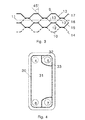
- Fig. 4 is a further top view of a general heat exchanger plate illustrating a gasket part 30 positioned close to the rim of the plate sealing the heat transfer area 31 from the externals.
- the gasket 32 traditionally are positioned in a gasket groove, or well, where the cross sections of groove and gasket often are shaped alike and the gasket groove usually has essentially flat bottoms, that if unsupported at the opposite side of the heat exchanger plate may risk to deform under e.g. media pressure or pre-pressurized gaskets by especially thin plates.
- Fig. 5 illustrates one solution according to the present invention, where a heat exchanger plate 15 comprising at a first wavy section 34 aligned with a second wavy 35 section of a neighbouring plate 16 thus defing a gasket section 37 between them, where the wavy sections 34, 35 in the illustration of Fig. 5 is the area between the lines 36.
- the gasket section 37 is where a gasket 30, 32 is to be be positioned between the two plates 15, 16 and thus extends in a length direction being longer than its transverse direction, where the length direction may form a straight linear tajectory, such as illustrated in e.g. Figs.8-10 or a curvatured trajectory such as illustrated e.g. in Figs. 13 and 14 .
- the transverse length may be constant or may be changing, such as illustrated e.g. in Fig. 7 , or it may itself be wavy, regular or irregular.
- the waves of the wavy sections 34, 35 may be waves in the plate 15, 16 surfaces and are in a first embodiment of the present invention such that the surface waves seen in the length direction, either with regular or irregular waves.
- the waves in the wavy sections 34, 35 extend with waves in the transverse direction, such that the waves may be either, or such that surface of the plates waves in both the length and transverse directions of the wavy sections 34, 35, where one way to form this is by shaping the wavy sections 34, 35 with first sets of dimples 22 corresponding to dimple tops of the upper plate 15 having flat first surface areas 19 and dimple bottoms 23 of the neighboring lower plate 16 having flat second surface areas 20, and where the wall sections from the edges of the dimples 22, 23 comprises no edges or corners but may be curved or straightnor does it comprise any flat unsuported surface areas parallel to the imagiary plane 11. That the flat surface areas 19, 20 are supported in the present context means they forms contact area to a flat surface opposite to the respective neighboring plate 16, 15. Unsupported in the same manner means it is not in contact with any such feature.
- unsupportet flat surfaces 19, 20 refer to planes essential parallel to the fictive plane 11, the waves may comprise unsupported turning tops and bottoms of the wavy structures.
- the waves are formed by dimples 22, 23where the flat first surface areas 19 within the first wavy section 34 forms a first contact face arranged against a contact face of a plane surface being upper to the plate 15, such as second surface areas 20 of dimple bottoms 23 of an upper plate.
- the flat second surface areas 20 within the second wavy section 35 forms a second contact face arranged against a contact face of a plane surface being lower to the plate 16,such as first surface areas 19 of dimple tops 22 of a lower plate.
- Fig.6 illustrate the same first wavy section 34 of the lower plate for the gasket section 37 Fig. 5 with a gasket 30, 32.
- the uncompressed gasket height usually is larger than the maximum height within the gasket section 37 from a first surface area to a second surface area such as at least 110%, this usually being the doubble of the distance form a first flat surface area 19 to a second flat surface area 20 of a plate 15.
- the gasket 32 may have flat top and bottom suraces or may have a wavy topology reflecting the surface structures of the wavy first and second sections 34, 35 but with an factor of e.g. 1,1 larger that the height between the wawy sections 34, 35. When the plates are mounted in the frame, the gasket will be deformed.
- each of the plates 15, 16 further may comprise respectively dimples 23a, 22a, reaching in the direction towards the gasket 30, 32 forming contact faces against the other of the respective of the two neighboring platesl5, 16, in the same manner as illustrated in e.g. Fig. 3 where first set dimples 22 of lower plate 15 forms contact faces agains second set dimples 23 of the upper plate 16. Since these will be positioned outside but at the edges of the wavy sections 34, 35 they forms edge dimples to the gasket section 37 helping both to strengthen it but also to confine and fix the gasket 30, 32 within the gasket section 37.
- the gaskets experience wavy 'sides' just as they lean against sloping sides. All of this assists in keeping the gasket firmly in position,
- the dimples 22, 23 may in one embodiment be special to the wavy sections 34, 35 different from the surface structures such as in the heat transfer area 31, either differently designed dimples or a quite different design such as fish bone.
- the whole of, or at least a section of the heat transfer area 31, and / or the opening area 33 and / or an optional transition zone therebetween comprises dimples 22, 23, the gasket simply being positioned in sections between the dimples.
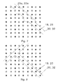
- Figs. 7-18 illustrates a number of different embodiments of the present invention where all the figures illustrate a top view of a plate 15, 16 the white shapes 22 representing eiher a first or a second set of dimples and the black shapes correspondingly representing the other of either the first or second kind of dimples 23.
- Fig. 7 thus illustrates a top view of a further embodiement of the present invention where the gasket is shaped to reach out of the openings formed between connected edge dimples 22a, 23a.
- This gasket design has the advangage of being more stable and to give an easier fixation during mounting.
- Fig. 8 illustrates a top view of an embodiment where the gasket may comprise branches extending in different directions.
- Fig. 9 illustrates a top view of an embodiment where the gasket may bend in different directions.
- Fig. 10 is an embodiment where the gasket changes direction and fig. 10 is an embodiment combining the embodiments of fig. 8 and 9 and further forming a sealed enclosure encircling e.g. a opening 4, 5, 6, 7.
- Fig. 11 illustrates a further embodiment where the wavy sections 34, 35 not only comprises dimples 22, 23 extending opposite to the gasket, but also a set of opposite directed dimples 22b, 23b extending towards the gasket just as the dimples at the sides of the wavy sections 34, 35, thus reaching through the gasket section 37 forming contact faces to the dimples of the other plate within the gasket section 37.
- the gasket 30, 32 in this gasket section 37 then will be shaped to allow the flat surface areas 19, 20 of the dimples 22b, 23b to contact, such as comprising openings 38 through the gasket 30, 32, or being essentially S-shaped making a slalom kind of trajectory around the the dimples 22b, 23b being in contact within the gasket section
- Fig. 12 illustrates an embodiment combining the featuers of figs. 8 and 11 .
- Fig. 13 illustrate an embodiment with cicular arranged wavy sections 34, 35 possible encircling an opening 4, 5, 6, 7, and in the illustrated embodiment having larger edge dimples 22a, 23a at the outside edge 39 than at the inner edge 40, though the opposite may also be the situation, or the outer and inner edge dimples being of the same size.
- the inner and outer edge dimples has different forms such as curvature of the walls or shape of the top and bottom surface areas.
- edge dimples 22a, 23 at the one side of the wavy sections 34, 35 may be differently shaped or differently sized relative to the edge dimples 22a, 23a at the other side.
- Fig. 14 illustrate an alternative embodiment with curved wavy sections 34, 35 spiralling away from a center section such as but not limited to an opening 4, 5, 6, 7, but any other curvatures of the trajectory of the wavy sections 34, 35 also applies to the present invention.
- dimple tops 19, 20 are differently sized to the dimple bottoms 20, 19, the plates thus positioned with the large dimples 23, 22 being top at one plate and the small dimples 22, 23 being bottoms, but vice verca at the neighboring plates, thus that dimples of essentially the same sizes and shapes forms the flat contact surfaces.
- Fig. 16 illustrate an alternative embodiment to that of Fig. 15 , but where the opposing dimples 22, 23 are of different size and shapes, such as respectively elliptical and circular.
- Fig. 17 illustrate an alternative embodiment to that of Fig. 15 , but where the opposing dimples 22, 23 are of different size and shapes, such as respectively elliptical and rectangular.
- the dimples 22, 23 are positioned in a lattice structure where each of the dimples 22 of the first set are neighboured by four dimples 23 of the second set and vice versa.
- the dimples 22, 23 could represent any of the dimples such as those forming the surface structures in the heat transfering area, in the opening area and / or in the transition zone between the opening and the heat transfering areas.
- rows 41 of lines of sight extends in a 45 degrees angle relative lattice directions given by arrows 42 and 43.
- These lines of sight forms natural wavy sections 34, 35 according to the present invention and could therefore in one embodiment of the present invention be used as gasket section 37, such as by sealing an opening area from the heat transfering area by connecting two egde parts 30 of the gasket with a part 32 extending at a 45 degrees angle relative to the lattice directions 42, 43 sealing off an opening 4, 5, 6, 7.
- all or some of the different dimples 12, 13, 22, 23, 22a, 22b, 23a, 23b may be similar shaped and sized.
Landscapes
- Engineering & Computer Science (AREA)
- Physics & Mathematics (AREA)
- Thermal Sciences (AREA)
- Mechanical Engineering (AREA)
- General Engineering & Computer Science (AREA)
- Heat-Exchange Devices With Radiators And Conduit Assemblies (AREA)
Abstract
Description
- The present invention relates to a heat exchanger of the kind where a plurality of plates is stacked and where they, due to surface structures, form flow paths between neighboring plates.
- Particularly, the invention relates to a gasket plate heat exchanger where the plates define gasket holding wavy sections where a gasket is located and / or squeezed between two neighbouring heat exchanger plates.
- A plate heat exchanger uses plates to transfer heat between two media, typically fluids flowing in separated first and second flow paths. Compared with a conventional heat exchanger, the fluids are exposed to a large surface area defined by the surfaces of the plates. This increases the exchange of thermal energy between the fluids.
- Plate heat exchangers are common for hot water boilers, and particularly for instantaneous preparation of domestic hot water or for heating circuits etc.
- The flow paths each connects to either a primary or a secondary fluid connection e.g. for supplying heating fluid or domestic hot water. The first and second flow paths are on opposite sides of the plates, and the plates come with a number of different structures such as fishbone or herringbone corrugations. When stacking fishbone heat exchanger plates, taken as an example, they are positioned such that they connect in crossing points of the corrugations and as the corrugations form relatively sharp pointed tops, the contact area between tops of adjacent plates becomes small and less well defined. In case the fluids are pressurized it results in concentrated contact forces leading to permanent deformations of the contact points.
- An alternative design is the surface structures to be defined as dimple patterns making it possible to design contact areas with well-defined areas, and thus well-defined and optimized strength and hydraulic characteristics.
- Due to the reduced speed variation of the media when passing through the heat exchanger profile, the profile height for the dimple pattern can be reduced by typically 30% compared to the traditional herring bone pattern and still maintaining the same pressure drop and heat transfer. The reduced profile height results in approximately twice the number of brazing points thus increasing the strength. Alternatively, thinner plates can be applied.
- The invention is related to gasket exchangers where the stack of heat exchanger plates are held together by an external force, such as when located and / or squeezed between top and bottom plates being fixed by bolts, and is based on the discovery that the essential in realizing a strong heat exchanger is not the surface area if the tops respectively bottoms of the dimples, but rather the length of their circumference.
- The heat exchanger plates may define inlets and outlets for the flow paths defined between neighboring plates, where these typically are formed as four corner openings connecting the fluid such that two openings connects a first fluid supply to an upper side of the plate by an inlet and an outlet and a second supply connecting to the two other openings on the lower side of the plate. Heat transferring areas then are formed in the flow paths from inlet to outlet by the surface structures. Opening areas are the areas in the circumference of the openings and usually comprises structures to support these. Further a transition zone may exist in the zone from the opening to the heat transferring areas for distributing the fluids to the full extent of the heat transferring area.
- For gasketed heat exchangers a gasket, or packing, usually are positioned close to the rim of the heat exchange plates encircling the heat transfer area to seal it from the externals preventing the fluids to leak out of the flow paths between the plates. This sealing will be necessary for the flow paths at both sides of any of the plates and thus by placing the upper and lower gasket relative to a plate at the same position they will form a support to the heat exchanger plate and thus protecting it from deformations due to the pressures of the media or the pre-pressurization of the gasket.
- Further as two of the openings are to communicate with the flow path formed at the upper side of a plate, and the other two to communicate with the flow path formed at the lower side, this means that two of the opening areas are to be sealed from the heat transferring area, meaning the one side of the plate relative to the other. Therefore the plates in these areas only will have a gasket at the one side and thus not being supported at the other side. One way to prevent the plates from deformations due to e.g. the media pressure or the pressurization of the gasket itself in this area is to introduce substantially thick plates. This however then leads to a reduction in the heat transfer, heavier heat exchangers and more use of raw materials.
- It is an object of the invention to provide other means to make a section of the plate designed to contain a gasket with sufficient strength even for thinner plates such as at 0.5 millimeters, or 0.4 mm, or 0.3 mm or even less, depending of the pressure rating of the heat exchanger. This especially is essential for the gasket in the opening area where the gasket is unsupported from the opposite plate side. There is only a gasket located in every second flow channel. This is generally known as a weak section of the gasket heat exchanger.
- This is solved by introducing a heat exchanger comprising plurality of stacked plates that due to surface structures forms flow paths between neighbouring plates, where at least one plate comprises at a first wavy section aligned with a second wavy section of a neighbouring plate and where a gasket is positioned between the first and second wavy sections, thereby forming a support for the neighboring flow paths where no gasket exists at the oppsing side of the plate in this section.
- By forming the waves of the first wavy section by a first set of dimples with flat first surface areas, and the waves of the second wavy section of the neighbouring plate by a second set of dimples protruding in the opposite direction relative to the first set of dimples and having flat second surface areas, where each dimple of the first set of dimples forms a first contact face arranged against a contact face of an adjacent plate, and each dimple of the second set of dimples forms a second contact face arranged against a contact face of an adjacentplate., then it increases the contact area of the neighboring plates and thus increases the strength of the section.
- The kind and nature of the wavy sections may be designed according to the need, suchas as forming a regular pattern of waves or a changing pattern of waves, even a irregular pattern of waves.
- To ensure the gakets may expand during possible minor deformations of the plates, and to assist fixing it firmly within the wavy section, the uncompressed gasket height is larger than the height from a first surface area to a second surface area, such as at least 110% of that of the height from a first surface area to a second surface area.
- In one embodiment at least a section of a gasket is positioned between said first and second wavy sections are positioned to separate a section of a plate comprising a port hole from the rest of the plate comprising a heat exchange area, thus sealing the port openings from the heat exchanging sections. This section is especially vunrable due to the lack of a supporting gasket at the neighboring sides of the plates.
- In one embodiment the undeformed gasket have flat upper and lower surfaces but deformed when positioned between the first and second wavy sections to a shape definde by the first and second wavy sections. This enables the possiblility to use standard gaskets where they simply are deformed into the gasket section between the wavy sections, and further helps keeping them firmly in position. The gasket then may deform through the openings in the sides formed between the side dimples.
- In an even more advanced embodiment of the present invention helping to keep the gasket even more firm in position, each plate comprises both first and second sets of dimples in the first and second wavy sections where the first sets of dimples of the first wavy section contacts second set of dimples of the second set of dimples through openings in the gasket.
- If the dimples of the first wavy section contacts dimples of the second wavy section through openings in the gasket this increases stability of the sections and helps fixing the gasket firmly.
- In one preferred embodiment of the present invention the surface structures forming the flow paths in the heat transferring sections of the plates also are formed by two sets of dimples protruding at the opposing sides of each plate and having flat surface areas forming contact faces arranged against contact faces of an adjacent plate. Then the gaskets simply are positioned in sections where they seales off selected sections from other sections.
- The gasket could also be positioned at the rim of the heat exchanger plates sealing the whole of the flow paths from the externals. In the embodimen where all the microstructures of all the sections of the plates are formed by dimples and when positioning the gasket in the naturally formed valleys of these dimples, this offers the special problem the opposing side of a plate does not form a vally free of dimples protruding in the direction towards the dimple, but rather the oppositie situation, hence the formed stability, and therefore one solution is to shift the gasket such that they at the opposing sides will be positioned slightly un-alinged in the next free valleys.
-
-
Fig. 1 illustrates a perspective view of a heat exchanger according to the invention; -
Fig. 2 illustrates in a top view, a plate heat exchanger; -
Fig. 3 illustrates a stack of plates in a sideview; -
Fig. 4 illustrates a plate for a heat exchanger including an example of the gasket; -
Figs. 5 illustrates two plates of the dimple type with an example of the gasket location inbetween, according to the invention; -
Fig. 6 illustrates one plate of the dimple type with an example of a compresssed gasket located into the gasket groove, according to the invention; -
Fig. 7 illustrates one plate of the dimple type with an example of a gasket geometry, according to the invention; -
Fig. 8 illustrates one plate of the dimple type with an example of a gasket geometry including branches, according to the invention; -
Fig. 9 illustrates one plate of the dimple type with an example of a gasket geometry including bending, according to the invention; -
Fig. 10 illustrates one plate of the dimple type with an example of a gasket geometry, according to the invention; -
Fig. 11 Illustrates one plate of the dimple type with an example of a gasket geometry, where some of the dimples reach trough the gasket, according to the invention; -
Fig. 12 Illustrates one plate of the dimple type with an example of a gasket geometry, where some of the dimples reach trough the gasket itself including a branch; -
Fig. 13 Illustrates one plate of the dimple type with an example of a gasket geometry, in an circular pattern; -
Fig. 14 Illustrates one plate of the dimple type with an example of a gasket geometry, in curved pattern; -
Fig. 15 Illustrates one plate of the dimple type with an example of a gasket geometry, where the top and bottom dimples have different size -
Fig. 16 Illustrates one plate of the dimple type with an example of a gasket geometry, where the top and bottom dimples have different shape and size; -
Fig. 17 Illustrates one plate of the dimple type with an example of a gasket geometry, where the top and bottom dimples have different shape and size; -
Fig. 18 Illustrates a special version of positioning the gasket to seal off an opening. - It should be understood that the detailed description and specific examples, while indicating embodiments of the invention, are given by way of illustration only, since various changes and modifications within the spirit and scope of the invention will become apparent to those skilled in the art from the detailed description.
-
Fig. 1 illustrates aplate heat exchanger 1 comprising a plurality ofheat exchanger plates 2 which are stacked in a stacking direction visualized by thearrow 3. The heat exchanging plates are stacked with tops against bottoms. -
Fig. 2 illustrates the heat exchanger in a top view of the dimple kind surface structure, this being the design of illustration, but the present invention may also apply to other designs such as fish bone. The heat exchanger plate has fourcorner openings openings openings - A dimple structure with flat dimple tops and bottoms is illustrated by the white and black
oval marks section 8 of the heat transfer area of the plate, where the dimples protrude in opposite directions. The plates could e.g. be made from a planar plate which is deformed by stamping to form the dimples extending in opposite directions relative to the central plane of the original planar plate. -
Fig. 3 shows fourplates dimples 12 having flattop areas 9 and a second set ofdimples 13 having flatbottom areas 10. The first and second sets of dimples extend from a fictive central plane 11 (illustrated for plate 15) in opposite directions away from the central plane. The plates and thus the dimples can be manufactured by pressing a thin plate of metal, e.g. stainless steel, aluminum, cobber, brass or zinc or plastic into the desired shape, e.g. in a die. The plates can also be made by molding, e.g. by pressure molding of plastic in a mold or die. - The figure illustrates a side view and the dimples could have top surfaces of any shape, e.g. an elliptical shaped design of dimples according to the embodiment of illustration of the present invention. Other shapes may apply, e.g. super-elliptically, rectangular etc. as long as they have a well-defined extension in a first direction and a well-defined extension in a second direction being orthogonal to the first direction.
- Further to be seen in the surface structure example of
figure 3 is how dimple tops 12 are placed againstdimple bottoms 13 of an upper neighboring plate and in the same manner that dimplebottoms 13 are connected to dimple tops 12 of the lower neighboring plate. -
Fig. 3 also illustrates that the side walls of the dimples are roughly 45 degrees, c.f. the angle indication. In this way, the top and bottom dimples are as close as possible to each other. This leads to a higher number of dimples and to a higher strength. The angle of 45 degrees is limited by e.g. the maximum elongation of the stainless steel material. For practical reasons, e.g. due to tolerances of the pressing tools, a smaller angle is often applied. The walls are smoothly formed by free floating of the material without sharp edges and without flat or plane plate sections except from those appearing at the dimple tops and dimple bottoms, i.e. where one plate meet an adjacent plate. - Any such additional flat section would have created weak sections and could have allowed a pressure difference between fluids in the first and second paths to deform the plates - potentially, plates could bulge and crack at the edges. There is no pressure gradient over the connected tops and bottoms as the same fluids flow with the same pressures at the opposing sides of the connections.
- The structure illustrated in
Fig. 3 enables a reduced plate thickness. Due to the absence of edges and flat sections between dimple tops and bottoms the pressures are directed into the dimple walls in a manner where they are absorbed essentially without plastic deformation. Further, all the connections have enlarged contact areas relative to the fishbone structures and the pressure-forces are therefore distributed over a larger area. - One drawback is, however, that the relatively large contact areas reduce the thermal distribution from one path to the other. This drawback is counteracted by an increased convective heat transfer for a given pressure loss and the ability to reduce the plate thicknesses which again contributes to an increased heat transfer.
- In the plate heat exchanger shown in
Fig. 3 are arranged such that the dimples of the first set of dimples form a first contact face arranged against contact faces of an adjacent plate, and such that the dimples of the second set of dimples form a second contact face arranged against a contact face of an adjacent plate. -
Fig. 4 is a further top view of a general heat exchanger plate illustrating agasket part 30 positioned close to the rim of the plate sealing theheat transfer area 31 from the externals. - Further two parts of the
gasket 32 are positioned to seal two of theopenings opening areas 33, from theheat transfer area 31. - The
gasket 32 traditionally are positioned in a gasket groove, or well, where the cross sections of groove and gasket often are shaped alike and the gasket groove usually has essentially flat bottoms, that if unsupported at the opposite side of the heat exchanger plate may risk to deform under e.g. media pressure or pre-pressurized gaskets by especially thin plates. -
Fig. 5 illustrates one solution according to the present invention, where aheat exchanger plate 15 comprising at a firstwavy section 34 aligned with a second wavy 35 section of a neighbouringplate 16 thus defing agasket section 37 between them, where thewavy sections Fig. 5 is the area between thelines 36. Thegasket section 37 is where agasket plates Figs.8-10 or a curvatured trajectory such as illustrated e.g. inFigs. 13 and 14 . The transverse length may be constant or may be changing, such as illustrated e.g. inFig. 7 , or it may itself be wavy, regular or irregular. - The waves of the
wavy sections plate - In an alternative or additional embodiment the waves in the
wavy sections wavy sections wavy sections dimples 22 corresponding to dimple tops of theupper plate 15 having flatfirst surface areas 19 anddimple bottoms 23 of the neighboringlower plate 16 having flatsecond surface areas 20, and where the wall sections from the edges of thedimples imagiary plane 11. That theflat surface areas plate - In the present context unsupportet
flat surfaces fictive plane 11, the waves may comprise unsupported turning tops and bottoms of the wavy structures.. - In the illustrated embodiment of example the waves are formed by
dimples 22, 23where the flatfirst surface areas 19 within the firstwavy section 34 forms a first contact face arranged against a contact face of a plane surface being upper to theplate 15, such assecond surface areas 20 ofdimple bottoms 23 of an upper plate. - Correspondingly the flat
second surface areas 20 within the secondwavy section 35 forms a second contact face arranged against a contact face of a plane surface being lower to theplate 16,such asfirst surface areas 19 of dimple tops 22 of a lower plate. -
Fig.6 illustrate the same firstwavy section 34 of the lower plate for thegasket section 37Fig. 5 with agasket - The uncompressed gasket height usually is larger than the maximum height within the
gasket section 37 from a first surface area to a second surface area such as at least 110%, this usually being the doubble of the distance form a firstflat surface area 19 to a secondflat surface area 20 of aplate 15. Thegasket 32 may have flat top and bottom suraces or may have a wavy topology reflecting the surface structures of the wavy first andsecond sections wawy sections - In the illustrated embodiment the dimples within the
wavy sections gasket upper plate 15 anddimple bottoms 23 of thelower plate 16, but each of theplates dimples gasket Fig. 3 where first set dimples 22 oflower plate 15 forms contact faces agains second set dimples 23 of theupper plate 16. Since these will be positioned outside but at the edges of thewavy sections gasket section 37 helping both to strengthen it but also to confine and fix thegasket gasket section 37. - Especially given the sloped sides of the
side dimples - Due to the volume preservation of the gasket material, when compressed the gasket material needs room for the thanslocated gasket material, and due to the construction with
edge dimples wavy sections gasket - The
dimples wavy sections heat transfer area 31, either differently designed dimples or a quite different design such as fish bone. - In another embodiment the whole of, or at least a section of the
heat transfer area 31, and / or theopening area 33 and / or an optional transition zone therebetween comprisesdimples -
Figs. 7-18 illustrates a number of different embodiments of the present invention where all the figures illustrate a top view of aplate white shapes 22 representing eiher a first or a second set of dimples and the black shapes correspondingly representing the other of either the first or second kind ofdimples 23. -
Fig. 7 thus illustrates a top view of a further embodiement of the present invention where the gasket is shaped to reach out of the openings formed betweenconnected edge dimples Fig. 8 illustrates a top view of an embodiment where the gasket may comprise branches extending in different directions. -
Fig. 9 illustrates a top view of an embodiment where the gasket may bend in different directions. -
Fig. 10 is an embodiment where the gasket changes direction andfig. 10 is an embodiment combining the embodiments offig. 8 and9 and further forming a sealed enclosure encircling e.g. aopening Fig. 11 illustrates a further embodiment where thewavy sections dimples dimples wavy sections gasket section 37 forming contact faces to the dimples of the other plate within the gasket section 37.Thegasket gasket section 37 then will be shaped to allow theflat surface areas dimples openings 38 through thegasket dimples gasket section 37. -
Fig. 12 illustrates an embodiment combining the featuers offigs. 8 and11 . -
Fig. 13 illustrate an embodiment with cicular arrangedwavy sections opening larger edge dimples outside edge 39 than at theinner edge 40, though the opposite may also be the situation, or the outer and inner edge dimples being of the same size. In one embodiment the inner and outer edge dimples has different forms such as curvature of the walls or shape of the top and bottom surface areas. - In general in relation to any of the embodiments the
edge dimples wavy sections edge dimples Fig. 14 illustrate an alternative embodiment with curvedwavy sections opening wavy sections Fig. 15 illustrate another alternative embodiment where the dimple tops 19, 20 are differently sized to thedimple bottoms large dimples small dimples -
Fig. 16 illustrate an alternative embodiment to that ofFig. 15 , but where the opposingdimples -
Fig. 17 illustrate an alternative embodiment to that ofFig. 15 , but where the opposingdimples - Looking at
fig. 18 illustraing a top view of a further embodiement of the present invention, thedimples dimples 22 of the first set are neighboured by fourdimples 23 of the second set and vice versa. In this embodiment thedimples - In such a
lattice structure rows 41 of lines of sight extends in a 45 degrees angle relative lattice directions given byarrows wavy sections gasket section 37, such as by sealing an opening area from the heat transfering area by connecting twoegde parts 30 of the gasket with apart 32 extending at a 45 degrees angle relative to thelattice directions opening - In this and most of the illustrated previous embodiments all or some of the
different dimples
Claims (19)
- A heat exchanger comprising plurality of stacked plates that due to surface structures forms flow paths between neighbouring plates, where at least one plate comprises at a first wavy section aligned with a second wavy section of a neighbouring plate, characterized in a gasket is positioned between the first and second wavy sections.
- A heat exchanger according to claim 1, wherein the waves are formed in a length direction of the trajectory of the gasket section 37.
- A heat exchanger according to claim 1 or 2, wherein the waves are formed in a transverse direction to the trajectory of the gasket section 37.
- A heat exchanger according to any of claims 1-3, where the waves of the first wavy section are formed by a first set of dimples with flat first surface areas, and the waves of the second wavy section of the neighbouring plate are formed by a second set of dimples protruding in the opposite direction relative to the first set of dimples and having flat second surface areas, and where each dimple of the first set of dimples forms a first contact face arranged against a contact face of an adjacent plate, and each dimple of the second set of dimples forms a second contact face arranged against a contact face of an adjacent plate.
- A heat exchanger according to claim 4 where all flat areas in said first and second wavy sections are aligned with neighbouring plates.
- A heat exchanger according to claim 4 or 5, where the first and second wavy sections form a regular pattern of waves.
- A heat exchanger according to claim 4 or 5, where the first and second wavy sections form a changing pattern of waves.
- A heat exchanger according to claim 7, where the first and second wavy sections form a irregular pattern of waves.
- A heat exchanger according to any of the preceding claims, where the uncompressed gasket height is larger than the height from a first surface area to a second surface area.
- A heat exchanger according to claim 9, where the uncompressed gasket height is at least 110% of that of the height from a first surface area to a second surface area.
- A heat exchanger according to any of the preceding claims where the gasket between said first and second wavy sections are positioned to separate a section of a plate comprising a port hole from the rest of the plate comprising a heat exchange area.
- A heat exchanger according to any of the preceding claims where gaskets only are positioned at one side the wavy sections of the plates
- A heat exchanger according to any of the claims 1-11, where gaskets are positioned at both sides of the wavy sections of the plates.
- A heat exchanger according to any of the preceding claims where the gaskets have flat upper and lower surfaces but are deformed when positioned between the first and second wavy sections
- A heat exchanger according to any of the preceding claims, where each plate comprises both first and second sets of dimples in the first and second wavy sections where the first sets of dimples of the first wavy section contacts second set of dimples of the second set of dimples through openings in the gasket.
- A heat exchanger according to any of the preceding claims, where dimples of the first wavy section contacts dimples of the second wavy section through openings in the gasket.
- A heat exchanger according to any of the preceding claims, where each of the first and second wavy sections comprises both first and second sets of dimples and where the gasket are squeezed between first sets of dimples of the first wavy section and second sets of dimples of the second wavy section and where second sets of dimples of the first wavy section contacts first set of dimples of the second wavy section through holes in the gasket.
- A heat exchanger according to any of the preceding claims where the surface structures forming the flow paths in the heat transferring sections of the plates also are formed by two sets of dimples protruding at the opposing sides of each plate and having flat surface areas forming contact faces arranged against contact faces of an adjacent plate.
- A heat exchanger where the first and second sets of dimples of the first and second wavy sections are part of the two sets of dimples according to claim 18.
Applications Claiming Priority (1)
| Application Number | Priority Date | Filing Date | Title |
|---|---|---|---|
| DKPA201400716 | 2014-12-10 |
Publications (2)
| Publication Number | Publication Date |
|---|---|
| EP3032208A1 true EP3032208A1 (en) | 2016-06-15 |
| EP3032208B1 EP3032208B1 (en) | 2017-04-19 |
Family
ID=54105736
Family Applications (1)
| Application Number | Title | Priority Date | Filing Date |
|---|---|---|---|
| EP15184715.9A Active EP3032208B1 (en) | 2014-12-10 | 2015-09-10 | Gasket groove for a plate heat exchanger |
Country Status (3)
| Country | Link |
|---|---|
| EP (1) | EP3032208B1 (en) |
| CN (1) | CN105698585B (en) |
| RU (1) | RU2626032C2 (en) |
Cited By (6)
| Publication number | Priority date | Publication date | Assignee | Title |
|---|---|---|---|---|
| CN106247829A (en) * | 2016-08-15 | 2016-12-21 | 安徽天祥空调科技有限公司 | A kind of preparation technology of plate type heat exchanger |
| EP3640577A3 (en) * | 2018-10-15 | 2020-07-29 | Danfoss A/S | Heat exchanger plate with strenghened diagonal area |
| US10775086B2 (en) | 2015-10-20 | 2020-09-15 | Danfoss A/S | Method for controlling a vapour compression system in ejector mode for a prolonged time |
| US10816245B2 (en) | 2015-08-14 | 2020-10-27 | Danfoss A/S | Vapour compression system with at least two evaporator groups |
| US11460230B2 (en) | 2015-10-20 | 2022-10-04 | Danfoss A/S | Method for controlling a vapour compression system with a variable receiver pressure setpoint |
| CN118176070A (en) * | 2021-12-02 | 2024-06-11 | 株式会社前川制作所 | Method for producing plate stack unit for heat exchanger |
Citations (6)
| Publication number | Priority date | Publication date | Assignee | Title |
|---|---|---|---|---|
| US2281754A (en) * | 1937-01-27 | 1942-05-05 | Cherry Burreil Corp | Heat exchanger |
| GB1043224A (en) * | 1961-09-05 | 1966-09-21 | Howden James & Co Ltd | Improvements in or relating to heat exchangers |
| WO1993006426A1 (en) * | 1991-09-16 | 1993-04-01 | Apv Corporation Limited | Plate heat exchanger |
| DE19540271C1 (en) * | 1995-10-28 | 1996-11-07 | Gea Ecoflex Gmbh | Plate heat exchanger with plates arranged in series |
| EP1722184A2 (en) * | 2005-05-09 | 2006-11-15 | DHP Engineering Co., Ltd., | Coupling structure of heat transfer plate and gasket of plate type heat exchanger |
| WO2009080692A1 (en) * | 2007-12-21 | 2009-07-02 | Alfa Laval Corporate Ab | Heat exchanger |
Family Cites Families (3)
| Publication number | Priority date | Publication date | Assignee | Title |
|---|---|---|---|---|
| SU974090A1 (en) * | 1979-03-05 | 1982-11-15 | Предприятие П/Я Р-6273 | Plate-type heat exchanging element |
| SE528847C2 (en) * | 2005-01-28 | 2007-02-27 | Alfa Laval Corp Ab | Gasket assembly for plate heat exchanger |
| CN102393155A (en) * | 2011-11-02 | 2012-03-28 | 山东大学 | Novel three-dimensional mesh base plate-typed heat exchanger |
-
2015
- 2015-09-10 EP EP15184715.9A patent/EP3032208B1/en active Active
- 2015-11-03 CN CN201510736976.XA patent/CN105698585B/en active Active
- 2015-12-03 RU RU2015151736A patent/RU2626032C2/en active
Patent Citations (6)
| Publication number | Priority date | Publication date | Assignee | Title |
|---|---|---|---|---|
| US2281754A (en) * | 1937-01-27 | 1942-05-05 | Cherry Burreil Corp | Heat exchanger |
| GB1043224A (en) * | 1961-09-05 | 1966-09-21 | Howden James & Co Ltd | Improvements in or relating to heat exchangers |
| WO1993006426A1 (en) * | 1991-09-16 | 1993-04-01 | Apv Corporation Limited | Plate heat exchanger |
| DE19540271C1 (en) * | 1995-10-28 | 1996-11-07 | Gea Ecoflex Gmbh | Plate heat exchanger with plates arranged in series |
| EP1722184A2 (en) * | 2005-05-09 | 2006-11-15 | DHP Engineering Co., Ltd., | Coupling structure of heat transfer plate and gasket of plate type heat exchanger |
| WO2009080692A1 (en) * | 2007-12-21 | 2009-07-02 | Alfa Laval Corporate Ab | Heat exchanger |
Cited By (7)
| Publication number | Priority date | Publication date | Assignee | Title |
|---|---|---|---|---|
| US10816245B2 (en) | 2015-08-14 | 2020-10-27 | Danfoss A/S | Vapour compression system with at least two evaporator groups |
| US10775086B2 (en) | 2015-10-20 | 2020-09-15 | Danfoss A/S | Method for controlling a vapour compression system in ejector mode for a prolonged time |
| US11460230B2 (en) | 2015-10-20 | 2022-10-04 | Danfoss A/S | Method for controlling a vapour compression system with a variable receiver pressure setpoint |
| CN106247829A (en) * | 2016-08-15 | 2016-12-21 | 安徽天祥空调科技有限公司 | A kind of preparation technology of plate type heat exchanger |
| EP3640577A3 (en) * | 2018-10-15 | 2020-07-29 | Danfoss A/S | Heat exchanger plate with strenghened diagonal area |
| US11333449B2 (en) | 2018-10-15 | 2022-05-17 | Danfoss A/S | Heat exchanger plate with strengthened diagonal area |
| CN118176070A (en) * | 2021-12-02 | 2024-06-11 | 株式会社前川制作所 | Method for producing plate stack unit for heat exchanger |
Also Published As
| Publication number | Publication date |
|---|---|
| RU2015151736A (en) | 2017-06-08 |
| CN105698585A (en) | 2016-06-22 |
| RU2626032C2 (en) | 2017-07-21 |
| CN105698585B (en) | 2018-06-22 |
| EP3032208B1 (en) | 2017-04-19 |
Similar Documents
| Publication | Publication Date | Title |
|---|---|---|
| EP3032208B1 (en) | Gasket groove for a plate heat exchanger | |
| JP6166375B2 (en) | Heat transfer plate and flat plate heat exchanger comprising such a heat transfer plate | |
| KR101445474B1 (en) | A heat exchanger plate and a plate heat exchanger | |
| AU2008354066B2 (en) | A plate heat exchanger | |
| US7490660B2 (en) | Coupling structure of heat transfer plate and gasket of plate type heat exchanger | |
| EP2878909A1 (en) | Plate-type heat exchanger and refrigeration cycle device comprising same | |
| KR20160114626A (en) | Heat exchanging board and board-type heat exchanger provided with heat exchanging board | |
| CN103217049B (en) | A kind of plate type heat exchanger and plate thereof | |
| EP3640577B1 (en) | Heat exchanger comprising plates with strenghened diagonal area | |
| EP3745072A1 (en) | A dual media safety heat exchanger | |
| US10145625B2 (en) | Dimple pattern gasketed heat exchanger | |
| US11639829B2 (en) | Gasket and assembly for a plate heat exchanger | |
| JP7328348B2 (en) | Heat transfer plates and plate heat exchangers | |
| EP2257758A1 (en) | A plate heat exchanger | |
| EP3489606B1 (en) | Heat transfer plate for plate heat exchanger and plate heat exchanger with the same | |
| KR101987599B1 (en) | The plate heat exchanger of welding type | |
| EP3812682A1 (en) | Lining for heat exchanger | |
| US20160146543A1 (en) | Plate heat exchanger | |
| US20190316847A9 (en) | Plate heat exchanger with dual flow path | |
| CN111141163A (en) | Welded plate heat exchanger | |
| CN109813159B (en) | Heat transfer plate for a plate heat exchanger and plate heat exchanger with a heat transfer plate |
Legal Events
| Date | Code | Title | Description |
|---|---|---|---|
| PUAI | Public reference made under article 153(3) epc to a published international application that has entered the european phase |
Free format text: ORIGINAL CODE: 0009012 |
|
| AK | Designated contracting states |
Kind code of ref document: A1 Designated state(s): AL AT BE BG CH CY CZ DE DK EE ES FI FR GB GR HR HU IE IS IT LI LT LU LV MC MK MT NL NO PL PT RO RS SE SI SK SM TR |
|
| AX | Request for extension of the european patent |
Extension state: BA ME |
|
| 17P | Request for examination filed |
Effective date: 20161206 |
|
| RBV | Designated contracting states (corrected) |
Designated state(s): AL AT BE BG CH CY CZ DE DK EE ES FI FR GB GR HR HU IE IS IT LI LT LU LV MC MK MT NL NO PL PT RO RS SE SI SK SM TR |
|
| GRAP | Despatch of communication of intention to grant a patent |
Free format text: ORIGINAL CODE: EPIDOSNIGR1 |
|
| INTG | Intention to grant announced |
Effective date: 20170202 |
|
| GRAS | Grant fee paid |
Free format text: ORIGINAL CODE: EPIDOSNIGR3 |
|
| GRAA | (expected) grant |
Free format text: ORIGINAL CODE: 0009210 |
|
| AK | Designated contracting states |
Kind code of ref document: B1 Designated state(s): AL AT BE BG CH CY CZ DE DK EE ES FI FR GB GR HR HU IE IS IT LI LT LU LV MC MK MT NL NO PL PT RO RS SE SI SK SM TR |
|
| REG | Reference to a national code |
Ref country code: GB Ref legal event code: FG4D |
|
| REG | Reference to a national code |
Ref country code: CH Ref legal event code: EP |
|
| REG | Reference to a national code |
Ref country code: AT Ref legal event code: REF Ref document number: 886393 Country of ref document: AT Kind code of ref document: T Effective date: 20170515 |
|
| REG | Reference to a national code |
Ref country code: IE Ref legal event code: FG4D |
|
| REG | Reference to a national code |
Ref country code: DE Ref legal event code: R096 Ref document number: 602015002326 Country of ref document: DE |
|
| REG | Reference to a national code |
Ref country code: NL Ref legal event code: MP Effective date: 20170419 |
|
| REG | Reference to a national code |
Ref country code: FR Ref legal event code: PLFP Year of fee payment: 3 |
|
| REG | Reference to a national code |
Ref country code: LT Ref legal event code: MG4D |
|
| REG | Reference to a national code |
Ref country code: AT Ref legal event code: MK05 Ref document number: 886393 Country of ref document: AT Kind code of ref document: T Effective date: 20170419 |
|
| PG25 | Lapsed in a contracting state [announced via postgrant information from national office to epo] |
Ref country code: NL Free format text: LAPSE BECAUSE OF FAILURE TO SUBMIT A TRANSLATION OF THE DESCRIPTION OR TO PAY THE FEE WITHIN THE PRESCRIBED TIME-LIMIT Effective date: 20170419 |
|
| PG25 | Lapsed in a contracting state [announced via postgrant information from national office to epo] |
Ref country code: LT Free format text: LAPSE BECAUSE OF FAILURE TO SUBMIT A TRANSLATION OF THE DESCRIPTION OR TO PAY THE FEE WITHIN THE PRESCRIBED TIME-LIMIT Effective date: 20170419 Ref country code: ES Free format text: LAPSE BECAUSE OF FAILURE TO SUBMIT A TRANSLATION OF THE DESCRIPTION OR TO PAY THE FEE WITHIN THE PRESCRIBED TIME-LIMIT Effective date: 20170419 Ref country code: GR Free format text: LAPSE BECAUSE OF FAILURE TO SUBMIT A TRANSLATION OF THE DESCRIPTION OR TO PAY THE FEE WITHIN THE PRESCRIBED TIME-LIMIT Effective date: 20170720 Ref country code: FI Free format text: LAPSE BECAUSE OF FAILURE TO SUBMIT A TRANSLATION OF THE DESCRIPTION OR TO PAY THE FEE WITHIN THE PRESCRIBED TIME-LIMIT Effective date: 20170419 Ref country code: HR Free format text: LAPSE BECAUSE OF FAILURE TO SUBMIT A TRANSLATION OF THE DESCRIPTION OR TO PAY THE FEE WITHIN THE PRESCRIBED TIME-LIMIT Effective date: 20170419 Ref country code: AT Free format text: LAPSE BECAUSE OF FAILURE TO SUBMIT A TRANSLATION OF THE DESCRIPTION OR TO PAY THE FEE WITHIN THE PRESCRIBED TIME-LIMIT Effective date: 20170419 Ref country code: NO Free format text: LAPSE BECAUSE OF FAILURE TO SUBMIT A TRANSLATION OF THE DESCRIPTION OR TO PAY THE FEE WITHIN THE PRESCRIBED TIME-LIMIT Effective date: 20170719 |
|
| PG25 | Lapsed in a contracting state [announced via postgrant information from national office to epo] |
Ref country code: SE Free format text: LAPSE BECAUSE OF FAILURE TO SUBMIT A TRANSLATION OF THE DESCRIPTION OR TO PAY THE FEE WITHIN THE PRESCRIBED TIME-LIMIT Effective date: 20170419 Ref country code: RS Free format text: LAPSE BECAUSE OF FAILURE TO SUBMIT A TRANSLATION OF THE DESCRIPTION OR TO PAY THE FEE WITHIN THE PRESCRIBED TIME-LIMIT Effective date: 20170419 Ref country code: LV Free format text: LAPSE BECAUSE OF FAILURE TO SUBMIT A TRANSLATION OF THE DESCRIPTION OR TO PAY THE FEE WITHIN THE PRESCRIBED TIME-LIMIT Effective date: 20170419 Ref country code: PL Free format text: LAPSE BECAUSE OF FAILURE TO SUBMIT A TRANSLATION OF THE DESCRIPTION OR TO PAY THE FEE WITHIN THE PRESCRIBED TIME-LIMIT Effective date: 20170419 Ref country code: BG Free format text: LAPSE BECAUSE OF FAILURE TO SUBMIT A TRANSLATION OF THE DESCRIPTION OR TO PAY THE FEE WITHIN THE PRESCRIBED TIME-LIMIT Effective date: 20170719 Ref country code: IS Free format text: LAPSE BECAUSE OF FAILURE TO SUBMIT A TRANSLATION OF THE DESCRIPTION OR TO PAY THE FEE WITHIN THE PRESCRIBED TIME-LIMIT Effective date: 20170819 |
|
| REG | Reference to a national code |
Ref country code: DE Ref legal event code: R097 Ref document number: 602015002326 Country of ref document: DE |
|
| PG25 | Lapsed in a contracting state [announced via postgrant information from national office to epo] |
Ref country code: SK Free format text: LAPSE BECAUSE OF FAILURE TO SUBMIT A TRANSLATION OF THE DESCRIPTION OR TO PAY THE FEE WITHIN THE PRESCRIBED TIME-LIMIT Effective date: 20170419 Ref country code: DK Free format text: LAPSE BECAUSE OF FAILURE TO SUBMIT A TRANSLATION OF THE DESCRIPTION OR TO PAY THE FEE WITHIN THE PRESCRIBED TIME-LIMIT Effective date: 20170419 Ref country code: CZ Free format text: LAPSE BECAUSE OF FAILURE TO SUBMIT A TRANSLATION OF THE DESCRIPTION OR TO PAY THE FEE WITHIN THE PRESCRIBED TIME-LIMIT Effective date: 20170419 Ref country code: EE Free format text: LAPSE BECAUSE OF FAILURE TO SUBMIT A TRANSLATION OF THE DESCRIPTION OR TO PAY THE FEE WITHIN THE PRESCRIBED TIME-LIMIT Effective date: 20170419 Ref country code: RO Free format text: LAPSE BECAUSE OF FAILURE TO SUBMIT A TRANSLATION OF THE DESCRIPTION OR TO PAY THE FEE WITHIN THE PRESCRIBED TIME-LIMIT Effective date: 20170419 |
|
| PLBE | No opposition filed within time limit |
Free format text: ORIGINAL CODE: 0009261 |
|
| STAA | Information on the status of an ep patent application or granted ep patent |
Free format text: STATUS: NO OPPOSITION FILED WITHIN TIME LIMIT |
|
| PG25 | Lapsed in a contracting state [announced via postgrant information from national office to epo] |
Ref country code: SM Free format text: LAPSE BECAUSE OF FAILURE TO SUBMIT A TRANSLATION OF THE DESCRIPTION OR TO PAY THE FEE WITHIN THE PRESCRIBED TIME-LIMIT Effective date: 20170419 Ref country code: IT Free format text: LAPSE BECAUSE OF FAILURE TO SUBMIT A TRANSLATION OF THE DESCRIPTION OR TO PAY THE FEE WITHIN THE PRESCRIBED TIME-LIMIT Effective date: 20170419 |
|
| 26N | No opposition filed |
Effective date: 20180122 |
|
| PG25 | Lapsed in a contracting state [announced via postgrant information from national office to epo] |
Ref country code: SI Free format text: LAPSE BECAUSE OF FAILURE TO SUBMIT A TRANSLATION OF THE DESCRIPTION OR TO PAY THE FEE WITHIN THE PRESCRIBED TIME-LIMIT Effective date: 20170419 Ref country code: MC Free format text: LAPSE BECAUSE OF FAILURE TO SUBMIT A TRANSLATION OF THE DESCRIPTION OR TO PAY THE FEE WITHIN THE PRESCRIBED TIME-LIMIT Effective date: 20170419 |
|
| REG | Reference to a national code |
Ref country code: IE Ref legal event code: MM4A |
|
| REG | Reference to a national code |
Ref country code: BE Ref legal event code: MM Effective date: 20170930 |
|
| PG25 | Lapsed in a contracting state [announced via postgrant information from national office to epo] |
Ref country code: LU Free format text: LAPSE BECAUSE OF NON-PAYMENT OF DUE FEES Effective date: 20170910 |
|
| PG25 | Lapsed in a contracting state [announced via postgrant information from national office to epo] |
Ref country code: IE Free format text: LAPSE BECAUSE OF NON-PAYMENT OF DUE FEES Effective date: 20170910 |
|
| REG | Reference to a national code |
Ref country code: FR Ref legal event code: PLFP Year of fee payment: 4 |
|
| PG25 | Lapsed in a contracting state [announced via postgrant information from national office to epo] |
Ref country code: BE Free format text: LAPSE BECAUSE OF NON-PAYMENT OF DUE FEES Effective date: 20170930 |
|
| PG25 | Lapsed in a contracting state [announced via postgrant information from national office to epo] |
Ref country code: MT Free format text: LAPSE BECAUSE OF NON-PAYMENT OF DUE FEES Effective date: 20170910 |
|
| REG | Reference to a national code |
Ref country code: CH Ref legal event code: PL |
|
| PG25 | Lapsed in a contracting state [announced via postgrant information from national office to epo] |
Ref country code: HU Free format text: LAPSE BECAUSE OF FAILURE TO SUBMIT A TRANSLATION OF THE DESCRIPTION OR TO PAY THE FEE WITHIN THE PRESCRIBED TIME-LIMIT; INVALID AB INITIO Effective date: 20150910 |
|
| PG25 | Lapsed in a contracting state [announced via postgrant information from national office to epo] |
Ref country code: LI Free format text: LAPSE BECAUSE OF NON-PAYMENT OF DUE FEES Effective date: 20180930 Ref country code: CH Free format text: LAPSE BECAUSE OF NON-PAYMENT OF DUE FEES Effective date: 20180930 |
|
| PG25 | Lapsed in a contracting state [announced via postgrant information from national office to epo] |
Ref country code: CY Free format text: LAPSE BECAUSE OF FAILURE TO SUBMIT A TRANSLATION OF THE DESCRIPTION OR TO PAY THE FEE WITHIN THE PRESCRIBED TIME-LIMIT Effective date: 20170419 |
|
| PG25 | Lapsed in a contracting state [announced via postgrant information from national office to epo] |
Ref country code: MK Free format text: LAPSE BECAUSE OF FAILURE TO SUBMIT A TRANSLATION OF THE DESCRIPTION OR TO PAY THE FEE WITHIN THE PRESCRIBED TIME-LIMIT Effective date: 20170419 |
|
| PG25 | Lapsed in a contracting state [announced via postgrant information from national office to epo] |
Ref country code: TR Free format text: LAPSE BECAUSE OF FAILURE TO SUBMIT A TRANSLATION OF THE DESCRIPTION OR TO PAY THE FEE WITHIN THE PRESCRIBED TIME-LIMIT Effective date: 20170419 |
|
| PG25 | Lapsed in a contracting state [announced via postgrant information from national office to epo] |
Ref country code: PT Free format text: LAPSE BECAUSE OF FAILURE TO SUBMIT A TRANSLATION OF THE DESCRIPTION OR TO PAY THE FEE WITHIN THE PRESCRIBED TIME-LIMIT Effective date: 20170419 |
|
| PG25 | Lapsed in a contracting state [announced via postgrant information from national office to epo] |
Ref country code: AL Free format text: LAPSE BECAUSE OF FAILURE TO SUBMIT A TRANSLATION OF THE DESCRIPTION OR TO PAY THE FEE WITHIN THE PRESCRIBED TIME-LIMIT Effective date: 20170419 |
|
| P01 | Opt-out of the competence of the unified patent court (upc) registered |
Effective date: 20230617 |
|
| PGFP | Annual fee paid to national office [announced via postgrant information from national office to epo] |
Ref country code: DE Payment date: 20250805 Year of fee payment: 11 |
|
| PGFP | Annual fee paid to national office [announced via postgrant information from national office to epo] |
Ref country code: GB Payment date: 20250731 Year of fee payment: 11 |
|
| PGFP | Annual fee paid to national office [announced via postgrant information from national office to epo] |
Ref country code: FR Payment date: 20250821 Year of fee payment: 11 |