EP3745072A1 - A dual media safety heat exchanger - Google Patents
A dual media safety heat exchanger Download PDFInfo
- Publication number
- EP3745072A1 EP3745072A1 EP19177262.3A EP19177262A EP3745072A1 EP 3745072 A1 EP3745072 A1 EP 3745072A1 EP 19177262 A EP19177262 A EP 19177262A EP 3745072 A1 EP3745072 A1 EP 3745072A1
- Authority
- EP
- European Patent Office
- Prior art keywords
- chamber
- medium
- heat exchanger
- apertures
- plate
- Prior art date
- Legal status (The legal status is an assumption and is not a legal conclusion. Google has not performed a legal analysis and makes no representation as to the accuracy of the status listed.)
- Withdrawn
Links
Images


Classifications
-
- F—MECHANICAL ENGINEERING; LIGHTING; HEATING; WEAPONS; BLASTING
- F28—HEAT EXCHANGE IN GENERAL
- F28F—DETAILS OF HEAT-EXCHANGE AND HEAT-TRANSFER APPARATUS, OF GENERAL APPLICATION
- F28F1/00—Tubular elements; Assemblies of tubular elements
- F28F1/003—Multiple wall conduits, e.g. for leak detection
-
- F—MECHANICAL ENGINEERING; LIGHTING; HEATING; WEAPONS; BLASTING
- F28—HEAT EXCHANGE IN GENERAL
- F28D—HEAT-EXCHANGE APPARATUS, NOT PROVIDED FOR IN ANOTHER SUBCLASS, IN WHICH THE HEAT-EXCHANGE MEDIA DO NOT COME INTO DIRECT CONTACT
- F28D9/00—Heat-exchange apparatus having stationary plate-like or laminated conduit assemblies for both heat-exchange media, the media being in contact with different sides of a conduit wall
- F28D9/0031—Heat-exchange apparatus having stationary plate-like or laminated conduit assemblies for both heat-exchange media, the media being in contact with different sides of a conduit wall the conduits for one heat-exchange medium being formed by paired plates touching each other
- F28D9/0043—Heat-exchange apparatus having stationary plate-like or laminated conduit assemblies for both heat-exchange media, the media being in contact with different sides of a conduit wall the conduits for one heat-exchange medium being formed by paired plates touching each other the plates having openings therein for circulation of at least one heat-exchange medium from one conduit to another
- F28D9/005—Heat-exchange apparatus having stationary plate-like or laminated conduit assemblies for both heat-exchange media, the media being in contact with different sides of a conduit wall the conduits for one heat-exchange medium being formed by paired plates touching each other the plates having openings therein for circulation of at least one heat-exchange medium from one conduit to another the plates having openings therein for both heat-exchange media
-
- F—MECHANICAL ENGINEERING; LIGHTING; HEATING; WEAPONS; BLASTING
- F28—HEAT EXCHANGE IN GENERAL
- F28F—DETAILS OF HEAT-EXCHANGE AND HEAT-TRANSFER APPARATUS, OF GENERAL APPLICATION
- F28F21/00—Constructions of heat-exchange apparatus characterised by the selection of particular materials
- F28F21/08—Constructions of heat-exchange apparatus characterised by the selection of particular materials of metal
- F28F21/081—Heat exchange elements made from metals or metal alloys
-
- F—MECHANICAL ENGINEERING; LIGHTING; HEATING; WEAPONS; BLASTING
- F28—HEAT EXCHANGE IN GENERAL
- F28F—DETAILS OF HEAT-EXCHANGE AND HEAT-TRANSFER APPARATUS, OF GENERAL APPLICATION
- F28F3/00—Plate-like or laminated elements; Assemblies of plate-like or laminated elements
- F28F3/08—Elements constructed for building-up into stacks, e.g. capable of being taken apart for cleaning
- F28F3/086—Elements constructed for building-up into stacks, e.g. capable of being taken apart for cleaning having one or more openings therein forming tubular heat-exchange passages
-
- F—MECHANICAL ENGINEERING; LIGHTING; HEATING; WEAPONS; BLASTING
- F28—HEAT EXCHANGE IN GENERAL
- F28F—DETAILS OF HEAT-EXCHANGE AND HEAT-TRANSFER APPARATUS, OF GENERAL APPLICATION
- F28F21/00—Constructions of heat-exchange apparatus characterised by the selection of particular materials
- F28F21/08—Constructions of heat-exchange apparatus characterised by the selection of particular materials of metal
- F28F21/081—Heat exchange elements made from metals or metal alloys
- F28F21/084—Heat exchange elements made from metals or metal alloys from aluminium or aluminium alloys
-
- F—MECHANICAL ENGINEERING; LIGHTING; HEATING; WEAPONS; BLASTING
- F28—HEAT EXCHANGE IN GENERAL
- F28F—DETAILS OF HEAT-EXCHANGE AND HEAT-TRANSFER APPARATUS, OF GENERAL APPLICATION
- F28F2265/00—Safety or protection arrangements; Arrangements for preventing malfunction
- F28F2265/16—Safety or protection arrangements; Arrangements for preventing malfunction for preventing leakage
-
- F—MECHANICAL ENGINEERING; LIGHTING; HEATING; WEAPONS; BLASTING
- F28—HEAT EXCHANGE IN GENERAL
- F28F—DETAILS OF HEAT-EXCHANGE AND HEAT-TRANSFER APPARATUS, OF GENERAL APPLICATION
- F28F2270/00—Thermal insulation; Thermal decoupling
- F28F2270/02—Thermal insulation; Thermal decoupling by using blind conduits
Definitions
- the present invention relates to a dual media safety heat exchanger comprising
- Dual media safety heat exchangers are known in the prior art. They are used to separate a working fluid to be cooled from a heat transfer medium in a heat exchanger. When special working fluid is being used which may not be mixed with a heat transfer medium, the heat exchanger has safety chambers incorporated between other medium chambers which act as a buffer zone between the medium chambers.
- all chamber plates are substantially identical in configu ration.
- the heat exchanger may comprise a plurality of first medium chambers, a plurality of second medium chambers and a plurality of intermediate chambers, all being arranged in a stacked manner.
- the chamber plates may be made from a blank material.
- the material may be metal, preferably aluminium or any alloys thereof.
- first inlet and the first outlet may be extending through the stacked chamber plates and provide a first inlet channel and a first outlet channel being fluidly connected with the plurality of first medium chambers
- second inlet and the second outlet may be extending through the stacked chamber plates and provide a second inlet channel and a second outlet channel being fluidly connected with the plurality of second medium chambers.
- first inlet channel may be configured to distribute the first medium to all the first medium chambers
- second inlet channel is configured to distribute the second medium to all the second medium chambers
- first medium chambers may be arranged in parallel in relation to the first inlet channel
- second medium chambers are arranged in parallel in relation to the second inlet channel.
- one or more turbulators may be arranged in the first medium chamber, the second medium chamber and/or the intermediate chamber.
- the intermediate chamber may comprise a chamber outlet wherefrom the first medium or the second medium eventually leaked into the intermediate chamber may be drained.
- embossments may enhance the heat transfer between the chambers and provide stability to the heat exchanger structure.
- embossments may be provided in the chamber plates, the embossments being herringbone-shaped.
- the herringbone-shaped embossments may be provided in the intermediate chamber when stacked.
- each chamber plate may be substantially square-formed provided with four apertures at each corner, the apertures are configured to defining the first inlet channel, the first outlet channel, the second inlet channel and the second outlet channel, respectively.
- the chamber plate may have a centre axis, two of the apertures are arranged on a first side of the centre axis and the other two apertures are arranged on a second side of the centre axis, the second side being opposite side of the first side in relation to the centre axis.
- the two apertures may be arranged on the first side being the first apertures and have a first diameter, the two apertures arranged on the second side being the second apertures have a second diameter, the first diameter being larger than the second diameter.
- the chamber plate may have a first face and a second face, first rim sections are provided around the first apertures, the first rim sections are projecting from the first face having a first distance, second rim sections are provided around the second apertures, the second rim sections are extending from the second face having a second distance.
- the second distance may be larger than the first distance, preferably the second distance is at least twice the distance of the first distance.
- a first end plate may be arranged on a first end of the stacked chamber plates, and a second end plate is arranged on a second end of the stacked chamber plates.
- the first end plate and the second end plate may be part of the stacked plates.
- chamber plates of the heat exchanger may be soldered together.
- the first medium may be oil or water.
- the second medium may be oil or water.
- the invention also relates to a method for preparing a dual media safety heat exchanger according to any of the preceding claims, comprising
- the connecting of the chamber plates may be performed by soldering.
- first end plate and a second end plate may be stacked with the chamber plates.
- the invention also relates to a use of a dual media safety heat exchanger as described above for applications wherein the first medium and the second medium may not be mixed.
- Fig. 1 shows a dual media safety heat exchanger 1 in a perspective view.
- the dual media safety heat exchanger 1 is configured to allow a first medium and a second medium flow through the heat exchanger 1.
- the dual media safety heat exchanger 1 comprises a first inlet 2 and a first outlet 3.
- the first inlet 2 and the first outlet 3 are fluidly connected with a first medium chamber (not shown) or a plurality of first medium chambers for allowing a first medium flowing through the heat exchanger 1.
- the dual media safety heat exchanger 1 also comprises a second inlet 4 and a second outlet 5.
- the second inlet 4 and the second outlet 5 are fluidly connected with a second medium chamber (not shown) or a plurality of second medium chambers for allowing a second medium flowing through the heat exchanger 1.
- the dual media safety heat exchanger 1 comprises a plurality of first medium chambers, a plurality of second medium chambers and a plurality of intermediate chambers being arranged between adjacent first medium chamber and second medium chamber, the intermediate chamber being configured to separate the first medium chamber from the second medium chamber so that the first medium is prevented from being mixed with the second medium or vice versa in the circumstance of a leak within the safety heat exchanger 1.
- the plurality of first medium chambers, the plurality of second medium chambers and the plurality of intermediate chambers are advantageously stacked on each other. The construction of the dual media safety heat exchanger 1 will be described further below.
- the dual media safety heat exchanger 1 is shown in a partly exploded view, the dual media safety heat exchanger 1 comprising a first medium chamber 6 configured to allow a first medium flow through the first medium chamber 6, a second medium chamber 7 configured to allow a second medium flow through the second medium chamber 7 and an intermediate chamber 8 arranged between the first medium chamber 6 and the second medium chamber 7.
- the intermediate chamber 8 is configured to separate the first medium chamber 6 from the second medium chamber 7 so that the first medium is prevented from being mixed with the second medium or vice versa in the circumstance of a leak within the safety heat exchanger 1.
- the heat exchanger 1 may comprise a plurality of first medium chambers 6, a plurality of second medium chambers 7 and a plurality of intermediate chambers 8 and thereby be configured to the specific heat transfer demand and application.
- the first medium chamber 6, the second medium chamber 7 and the intermediate chamber 8 are defined by a plurality of chamber plates 9 having a configuration.
- the configuration of each chamber plate 9 is substantially identical irrespective of which chamber 6, 7, 8 it is part of.
- configuration means the design and layout of the chamber plates.
- the chamber plates 9 may be made from a blank material.
- the material is metal, preferably aluminium or any alloys thereof.
- each chamber plate 9 is substantially square-formed provided with four apertures, one at each corner.
- the apertures are configured to defining the first inlet channel, the first outlet channel, the second inlet channel and the second outlet channel, respectively.
- the chamber plate 9 has a centre axis A, two of the apertures are arranged on a first side 10 of the centre axis, and the other two apertures are arranged on a second side 11 of the centre axis, the second side 11 being opposite side of the first side 10 in relation to the centre axis A.
- the two apertures arranged on the first side 10 being the first apertures 12 have a first diameter D1
- the two apertures arranged on the second side 11 being the second apertures 13 have a second diameter D2, the first diameter D1 being larger than the second diameter D2.
- the chamber plate 9 has a first face 14 and a second face 15, first rim sections 16 are provided around the first apertures 12, the first rim sections 16 project from the first face 14 having a first height h1.
- Second rim sections 17 are provided around the second apertures 13, the second rim sections 17 project from the second face 15 having a second height h2.
- the second distance is larger than the first distance, preferably the second distance is at least twice the distance of the first distance.
- the heat exchanger 1 also comprises a first end plate 18 being arranged on a first end 20 of the stacked chamber plates 9 and a second end plate 19 being arranged on a second end 21 of the stacked chamber plates 9, whereby the first end plate 18 and the second end plate 19 are part of the stacked plates defining the heat exchanger 1.
- the first end plate 18 and the second end plate 19 being different of the chamber plates 9, however, is made in the same size as the chamber plates.
- the end plates 18, 19 may also be part of defining either a first medium chamber, a second medium chamber or an intermediate chamber.
- the first end plate 18 comprises the first inlet 2, the first outlet 3, the second inlet 4 and the second outlet 5.
- the second end plate 19 has in this embodiment four plug parts 22 being configured close off the first inlet channel, the first outlet channel, the second inlet channel and the second outlet channel.
- Each chamber plate 9 also has an embossment section 23 which projects from the first face 14 and is extending around near the circumference of the chamber plate 9.
- Each chamber plate 9 also has an edge section 24 which projects from the second face 15 and is extending around the circumference of the chamber plate 9.
- the edge section 24 is arranged closer to the circumference than the embossment section 23.
- the embossment section 23 and the edge section 24 are configured to provide a space between adjacent chamber plates 9 when they are being stacked whereby the chambers are created between the chamber plates 9.
- the edge section 24 comprises two depressions 25.
- the depressions 25 provide two chamber outlets 26 of the intermediate chamber 8 when the chamber plates 9 are stacked.
- the chamber outlets 26 are configured to drain the first medium or the second medium which has eventually leaked into the intermediate chamber from the adjacent first medium chamber and/or the adjacent second medium chamber.
- Figs. 3 and 4 show the heat exchanger 1 in two different cross-sectional views.
- the chamber plates 9 are stacked for providing the first medium chambers, the second medium chambers and the intermediate chambers.
- Fig. 3 shows a cross-sectional view taken along the longitudinal extension of the heat exchanger 1.
- the first medium chamber has a first inlet 2 and a first outlet 3.
- the first inlet 2 and the first outlet 3 are extending through the stacked chamber plates 9 and provide a first inlet channel 27 and a first outlet channel 28 being fluidly connected with the plurality of first medium chambers.
- the second medium chamber has a second inlet and a second outlet.
- the second inlet and the second outlet are extending through the stacked chamber plates 9 and provide a second inlet channel (not shown) and a second outlet channel being fluidly connected with the plurality of second medium chambers.
- FIG. 4 another cross-sectional view is shown.
- the first inlet 2 and the first inlet channel 27 and the second outlet 5 and the second outlet channel 29 are shown.
- Fig. 4 also shows how the identical chamber plates 9 are stacked for providing the heat exchanger 1 and the first end plate 18 and the second end plate 19. As shown, the embossment sections 23 of two adjacent chamber plates 9 are abutting, and the edge sections 24 of two adjacent chamber plates 9 are also abutting for providing the chambers between them.
- the second rim section 17 is configured to abut another second rim section of a chamber plate 9 being in a position where two other chamber plates 9 are arranged between them. Hence, the abutment of two second rim sections provide the channel through the chamber plates 9.
- all the chamber plates 9 and end plates 18, 19 are soldered together in leak-tight manner.
- the heights of the projecting first and second rim sections 16, 17 are shown (see also Fig. 2 ).
- Fig. 5 shows the same cross-sectional view as in Fig. 4 with a first medium 30 and a second medium 31 flowing in the heat exchanger 1.
- the first inlet channel 27 is configured to distribute the first medium 30 to all the first medium chambers 6.
- the second inlet channel (not shown) is configured to distribute the second medium to all the second medium chambers.
- the second outlet channel 29 is shown and the second medium chamber 7. Between the first medium chambers 6 and the second medium chambers 7, the intermediate chambers 8 are arranged providing safety to the heat exchanger 1.
- the first medium chambers 6 are arranged in parallel in relation to the first inlet channel 27.
- the second medium chambers (not shown) are arranged in parallel in relation to the second inlet channel.
- Fig. 6 shows in a partly exploded view the flow of the first medium 30 and the second medium 31 through the heat exchanger 1.
- the first medium 30 enters through the first inlet 2 and therefrom into the first inlet channel and hereinafter into the first medium chambers 6 wherefrom it is led out of the heat exchanger 1 via the first outlet channel to the first outlet 3.
- the second medium 31 enters through the second inlet 4 and therefrom into the second inlet channel and hereinafter into the second medium chambers 7 wherefrom it is led out of the heat exchanger 1 via the second outlet channel to the second outlet 5.
- the two media flow counter current through the heat exchanger 1.
- one or more turbulators may be arranged in the first medium chamber, the second medium chamber and/or the intermediate chamber.
- Fig. 7 shows another embodiment of the heat exchanger 1.
- the construction of the heat exchanger 1 is substantially identical with the one described above.
- the chamber plates 9 are provided with a plurality of embossments 32.
- the embossments 32 are configured to abut in the intermediate chamber 8 whereby the heat transfer through the intermediate chamber 8 is enhanced.
- the embossments 32 furthermore provide structure to the heat exchanger 1.
- Fig. 8a the chamber plate 9 is shown in a top view.
- the plurality of embossment 32 are provided in the chamber plate 9.
- the chamber plate has the same configuration as described above in that inter alia provided with the first inlet 2, the first outlet 3, the second inlet 4 and the second outlet 5.
- the first rim section 16 is seen surrounding the second rim section 17, the first and second rim sections being separated by a safety passage 40.
- Fig. 8b a cross-sectional view taken along the line VIIIB of Fig. 8a is shown.
- Two chamber plates 9 are stacked in the predetermined manner having the plurality of embossments 32.
- the embossments 32 of two adjacent chamber plates 9 are abutting so that the intermediate chamber 8 is provided with enhanced heat transfer and structure.
- an enlarged view of the details of the chamber plates 9 near the second inlet 4 and the second outlet 5 is shown. It is shown that the second rim section 17 having a height h1 projects to the same level as the first rim section 16 having a lower height h2.
- a safety passage 40 is present.
- the embossments 32 are in the present embodiment shown as being herring-bone shaped. Other configurations of the embossments may be applied.
- the first medium may be the medium which has to be treated, for instance cooled.
- the second medium may then be the heat transfer medium configured to cool the first medium.
- the connecting of the chamber plates may be performed by means of soldering.
Abstract
The present invention relates to a dual media safety heat exchanger comprising a first medium chamber configured to allow a first medium flow through the first medium chamber, a second medium chamber configured to allow a second medium flow through the second medium chamber and an intermediate chamber arranged between the first medium chamber and the second medium chamber and being configured to separate the first medium chamber from the second medium chamber so that the first medium is prevented from being mixed with the second medium or vice versa in the circumstance of a leak within the safety heat exchanger. The first medium chamber, the second medium chamber and the intermediate chamber are arranged in a stacked manner, the first medium chamber having a first inlet and a first outlet, the second medium chamber having a second inlet and a second outlet, the first medium chamber, the second medium chamber and the intermediate chamber being defined by a plurality of chamber plates having a configuration, wherein the configuration of each chamber plate is substantially identical irrespective of which chamber it is part of. The invention also relates to a method for preparing a dual media safety heat exchanger.
Description
- The present invention relates to a dual media safety heat exchanger comprising
- a first medium chamber configured to allow a first medium flow through the first medium chamber,
- a second medium chamber configured to allow a second medium flow through the second medium chamber, and
- an intermediate chamber arranged between the first medium chamber and the second medium chamber and being configured to separate the first medium chamber from the second medium chamber so that the first medium is prevented from being mixed with the second medium or vice versa in the circumstance of a leak within the safety heat exchanger,
- the first medium chamber, the second medium chamber and the intermediate chamber being arranged in a stacked manner,
- the first medium chamber having a first inlet and a first outlet,
- the second medium chamber having a second inlet and a second outlet,
- the first medium chamber, the second medium chamber and the intermediate chamber being defined by a plurality of chamber plates having a configuration.
- Dual media safety heat exchangers are known in the prior art. They are used to separate a working fluid to be cooled from a heat transfer medium in a heat exchanger. When special working fluid is being used which may not be mixed with a heat transfer medium, the heat exchanger has safety chambers incorporated between other medium chambers which act as a buffer zone between the medium chambers.
- However, due to the special construction of the known heat exchangers they may be difficult to manufacture which may often jeopardise leakage tightness of the chambers which again may result in unintended leak of the working fluid and/or heat transfer medium, and hence a potential mix of the fluids.
- Accordingly, there is a need for providing an enhanced dual media safety heat exchanger.
- It is an object of the present invention to wholly or partly overcome the above disadvantages and drawbacks of the prior art. More specifically, it is an object to provide an improved dual media safety heat exchanger which has enhanced fluid tightness and at the same time is easy to manufacture without jeopardising the heat transfer properties between a first medium and a second medium.
- The above objects, together with numerous other objects, advantages and features, which will become evident from the below description, are accomplished by a solution in accordance with the present invention by a dual media safety heat exchanger comprising
- a first medium chamber configured to allow a first medium flow through the first medium chamber,
- a second medium chamber configured to allow a second medium flow through the second medium chamber, and
- an intermediate chamber arranged between the first medium chamber and the second medium chamber and being configured to separate the first medium chamber from the second medium chamber so that the first medium is prevented from being mixed with the second medium or vice versa in the circumstance of a leak within the safety heat exchanger,
- the first medium chamber, the second medium chamber and the intermediate chamber being arranged in a stacked manner,
- the first medium chamber having a first inlet and a first outlet,
- the second medium chamber having a second inlet and a second outlet,
- the first medium chamber, the second medium chamber and the intermediate chamber being defined by a plurality of chamber plates having a configuration, wherein the configuration of each chamber plate is substantially identical irrespective of which chamber it is part of.
- According to the inventive idea, all chamber plates are substantially identical in configu ration.
- Furthermore, the heat exchanger may comprise a plurality of first medium chambers, a plurality of second medium chambers and a plurality of intermediate chambers, all being arranged in a stacked manner.
- Moreover, the chamber plates may be made from a blank material.
- The material may be metal, preferably aluminium or any alloys thereof.
- Also, the first inlet and the first outlet may be extending through the stacked chamber plates and provide a first inlet channel and a first outlet channel being fluidly connected with the plurality of first medium chambers, the second inlet and the second outlet may be extending through the stacked chamber plates and provide a second inlet channel and a second outlet channel being fluidly connected with the plurality of second medium chambers.
- In addition, the first inlet channel may be configured to distribute the first medium to all the first medium chambers, and the second inlet channel is configured to distribute the second medium to all the second medium chambers.
- Furthermore, the first medium chambers may be arranged in parallel in relation to the first inlet channel, and the second medium chambers are arranged in parallel in relation to the second inlet channel.
- Also, one or more turbulators may be arranged in the first medium chamber, the second medium chamber and/or the intermediate chamber.
- Moreover, the intermediate chamber may comprise a chamber outlet wherefrom the first medium or the second medium eventually leaked into the intermediate chamber may be drained.
- Further, the embossments may enhance the heat transfer between the chambers and provide stability to the heat exchanger structure.
- Additionally, embossments may be provided in the chamber plates, the embossments being herringbone-shaped.
- The herringbone-shaped embossments may be provided in the intermediate chamber when stacked.
- Also, each chamber plate may be substantially square-formed provided with four apertures at each corner, the apertures are configured to defining the first inlet channel, the first outlet channel, the second inlet channel and the second outlet channel, respectively.
- Moreover, the chamber plate may have a centre axis, two of the apertures are arranged on a first side of the centre axis and the other two apertures are arranged on a second side of the centre axis, the second side being opposite side of the first side in relation to the centre axis.
- The two apertures may be arranged on the first side being the first apertures and have a first diameter, the two apertures arranged on the second side being the second apertures have a second diameter, the first diameter being larger than the second diameter.
- Furthermore, the chamber plate may have a first face and a second face, first rim sections are provided around the first apertures, the first rim sections are projecting from the first face having a first distance, second rim sections are provided around the second apertures, the second rim sections are extending from the second face having a second distance.
- Also, the second distance may be larger than the first distance, preferably the second distance is at least twice the distance of the first distance.
- A first end plate may be arranged on a first end of the stacked chamber plates, and a second end plate is arranged on a second end of the stacked chamber plates.
- The first end plate and the second end plate may be part of the stacked plates.
- Furthermore, the chamber plates of the heat exchanger may be soldered together.
- The first medium may be oil or water.
- The second medium may be oil or water.
- The invention also relates to a method for preparing a dual media safety heat exchanger according to any of the preceding claims, comprising
- providing a plurality of chamber plates being substantially identical,
- providing a first chamber plate,
- providing a second chamber plate,
- stacking the second chamber plate on top of the first chamber plate by arranging the second face of the first chamber plate opposite to the second face of the second
- chamber plate while aligning the first apertures of the first chamber plate with the second apertures of the second chamber plate,
- providing a third chamber plate,
- stacking the third chamber plate on top of the second chamber plate by arranging the first face of the third chamber plate opposite to the first face of the second chamber plate while aligning the second apertures of the second chamber plate with the second apertures of the third chamber plate,
- providing a fourth chamber plate,
- stacking the fourth chamber plate on top of the third chamber plate by arranging the second face of the third chamber plate opposite to the second face of the fourth chamber plate while aligning the first apertures of the third chamber plate with the second apertures of the fourth chamber plate,
- continuing stacking chamber plates in the same manner until a predetermined size of the heat exchanger is obtained, and
- connecting the chamber plates in a fluid tight manner providing the first medium chambers, the second medium chamber and the intermediate chambers.
- The connecting of the chamber plates may be performed by soldering.
- In addition, a first end plate and a second end plate may be stacked with the chamber plates.
- The invention also relates to a use of a dual media safety heat exchanger as described above for applications wherein the first medium and the second medium may not be mixed.
- The invention and its many advantages will be described in more detail below with reference to the accompanying schematic drawings, which for the purpose of illustration show some non-limiting embodiments and in which
-
Fig. 1 shows a dual media safety heat exchanger according to the invention, -
Fig. 2 shows the dual media safety heat exchanger ofFig. 1 in a partly exploded view, -
Fig. 3 shows a cross-sectional view of the dual media safety heat exchanger ofFig. 1 , -
Fig. 4 shows another cross-sectional view of the dual media safety heat exchanger ofFig. 1 , -
Fig. 5 shows the cross-sectional view ofFig. 4 with the first medium and the second medium, -
Fig. 6 shows a partly exploded view of the dual media safety heat exchanger ofFig. 1 indicating the flow of the first medium and the second medium, -
Fig. 7 shows another embodiment of the dual media safety heat exchanger, and -
Figs. 8a and8b show an embodiment of a chamber plate and a cross-sectional view of two chamber plates being connected. - All the figures are highly schematic and not necessarily to scale, and they show only those parts which are necessary in order to elucidate the invention, other parts being omitted or merely suggested.
-
Fig. 1 shows a dual mediasafety heat exchanger 1 in a perspective view. The dual mediasafety heat exchanger 1 is configured to allow a first medium and a second medium flow through theheat exchanger 1. - The dual media
safety heat exchanger 1 comprises afirst inlet 2 and afirst outlet 3. Thefirst inlet 2 and thefirst outlet 3 are fluidly connected with a first medium chamber (not shown) or a plurality of first medium chambers for allowing a first medium flowing through theheat exchanger 1. The dual mediasafety heat exchanger 1 also comprises asecond inlet 4 and asecond outlet 5. Thesecond inlet 4 and thesecond outlet 5 are fluidly connected with a second medium chamber (not shown) or a plurality of second medium chambers for allowing a second medium flowing through theheat exchanger 1. - The dual media
safety heat exchanger 1 according to the present invention comprises a plurality of first medium chambers, a plurality of second medium chambers and a plurality of intermediate chambers being arranged between adjacent first medium chamber and second medium chamber, the intermediate chamber being configured to separate the first medium chamber from the second medium chamber so that the first medium is prevented from being mixed with the second medium or vice versa in the circumstance of a leak within thesafety heat exchanger 1. The plurality of first medium chambers, the plurality of second medium chambers and the plurality of intermediate chambers are advantageously stacked on each other. The construction of the dual mediasafety heat exchanger 1 will be described further below. - In
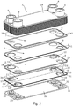
Fig. 2 the dual mediasafety heat exchanger 1 is shown in a partly exploded view, the dual mediasafety heat exchanger 1 comprising a firstmedium chamber 6 configured to allow a first medium flow through the firstmedium chamber 6, a secondmedium chamber 7 configured to allow a second medium flow through the secondmedium chamber 7 and anintermediate chamber 8 arranged between the firstmedium chamber 6 and the secondmedium chamber 7. As mentioned above, theintermediate chamber 8 is configured to separate the firstmedium chamber 6 from the secondmedium chamber 7 so that the first medium is prevented from being mixed with the second medium or vice versa in the circumstance of a leak within thesafety heat exchanger 1. - As shown in
Fig. 2 , the firstmedium chamber 6, the secondmedium chamber 7 and theintermediate chamber 8 are arranged in a stacked manner. Theheat exchanger 1 may comprise a plurality of firstmedium chambers 6, a plurality of secondmedium chambers 7 and a plurality ofintermediate chambers 8 and thereby be configured to the specific heat transfer demand and application. - The first
medium chamber 6, the secondmedium chamber 7 and theintermediate chamber 8 are defined by a plurality ofchamber plates 9 having a configuration. The configuration of eachchamber plate 9 is substantially identical irrespective of whichchamber - The term "configuration" means the design and layout of the chamber plates.
- The
chamber plates 9 may be made from a blank material. The material is metal, preferably aluminium or any alloys thereof. - In the present embodiment, each
chamber plate 9 is substantially square-formed provided with four apertures, one at each corner. The apertures are configured to defining the first inlet channel, the first outlet channel, the second inlet channel and the second outlet channel, respectively. - The
chamber plate 9 has a centre axis A, two of the apertures are arranged on afirst side 10 of the centre axis, and the other two apertures are arranged on asecond side 11 of the centre axis, thesecond side 11 being opposite side of thefirst side 10 in relation to the centre axis A. The two apertures arranged on thefirst side 10 being thefirst apertures 12 have a first diameter D1, the two apertures arranged on thesecond side 11 being thesecond apertures 13 have a second diameter D2, the first diameter D1 being larger than the second diameter D2. - Furthermore, the
chamber plate 9 has afirst face 14 and a second face 15,first rim sections 16 are provided around thefirst apertures 12, thefirst rim sections 16 project from thefirst face 14 having a first height h1.Second rim sections 17 are provided around thesecond apertures 13, thesecond rim sections 17 project from the second face 15 having a second height h2. The second distance is larger than the first distance, preferably the second distance is at least twice the distance of the first distance. Hereby is obtained that when thechamber plates 9 are stacked in correct manner, thesecond rim sections 17 may project up in thefirst apertures 12. - How the plurality of
chamber plates 9 are stacked for providing the first medium chambers, the second medium chambers and the intermediate chambers will be described further below. - The
heat exchanger 1 also comprises afirst end plate 18 being arranged on a first end 20 of the stackedchamber plates 9 and asecond end plate 19 being arranged on asecond end 21 of the stackedchamber plates 9, whereby thefirst end plate 18 and thesecond end plate 19 are part of the stacked plates defining theheat exchanger 1. In the present embodiment, thefirst end plate 18 and thesecond end plate 19 being different of thechamber plates 9, however, is made in the same size as the chamber plates. Theend plates first end plate 18 comprises thefirst inlet 2, thefirst outlet 3, thesecond inlet 4 and thesecond outlet 5. Thesecond end plate 19 has in this embodiment fourplug parts 22 being configured close off the first inlet channel, the first outlet channel, the second inlet channel and the second outlet channel. - Each
chamber plate 9 also has anembossment section 23 which projects from thefirst face 14 and is extending around near the circumference of thechamber plate 9. - Each
chamber plate 9 also has anedge section 24 which projects from the second face 15 and is extending around the circumference of thechamber plate 9. Theedge section 24 is arranged closer to the circumference than theembossment section 23. - The
embossment section 23 and theedge section 24 are configured to provide a space betweenadjacent chamber plates 9 when they are being stacked whereby the chambers are created between thechamber plates 9. - In the present embodiment, the
edge section 24 comprises twodepressions 25. Thedepressions 25 provide twochamber outlets 26 of theintermediate chamber 8 when thechamber plates 9 are stacked. Thechamber outlets 26 are configured to drain the first medium or the second medium which has eventually leaked into the intermediate chamber from the adjacent first medium chamber and/or the adjacent second medium chamber. -
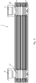
Figs. 3 and4 show theheat exchanger 1 in two different cross-sectional views. Thechamber plates 9 are stacked for providing the first medium chambers, the second medium chambers and the intermediate chambers. -
Fig. 3 shows a cross-sectional view taken along the longitudinal extension of theheat exchanger 1. As mentioned above, the first medium chamber has afirst inlet 2 and afirst outlet 3. In the present embodiment, thefirst inlet 2 and thefirst outlet 3 are extending through thestacked chamber plates 9 and provide afirst inlet channel 27 and afirst outlet channel 28 being fluidly connected with the plurality of first medium chambers. - In the same manner, the second medium chamber has a second inlet and a second outlet. In the present embodiment, the second inlet and the second outlet are extending through the
stacked chamber plates 9 and provide a second inlet channel (not shown) and a second outlet channel being fluidly connected with the plurality of second medium chambers. - In
Fig. 4 , another cross-sectional view is shown. Thefirst inlet 2 and thefirst inlet channel 27 and thesecond outlet 5 and thesecond outlet channel 29 are shown. -
Fig. 4 also shows how theidentical chamber plates 9 are stacked for providing theheat exchanger 1 and thefirst end plate 18 and thesecond end plate 19. As shown, theembossment sections 23 of twoadjacent chamber plates 9 are abutting, and theedge sections 24 of twoadjacent chamber plates 9 are also abutting for providing the chambers between them. - In addition, the
second rim section 17 is configured to abut another second rim section of achamber plate 9 being in a position where twoother chamber plates 9 are arranged between them. Hence, the abutment of two second rim sections provide the channel through thechamber plates 9. - Preferably, all the
chamber plates 9 andend plates second rim sections Fig. 2 ). -
Fig. 5 shows the same cross-sectional view as inFig. 4 with afirst medium 30 and a second medium 31 flowing in theheat exchanger 1. Thefirst inlet channel 27 is configured to distribute the first medium 30 to all the firstmedium chambers 6. In the same manner, the second inlet channel (not shown) is configured to distribute the second medium to all the second medium chambers. InFig. 5 , thesecond outlet channel 29 is shown and the secondmedium chamber 7. Between the firstmedium chambers 6 and the secondmedium chambers 7, theintermediate chambers 8 are arranged providing safety to theheat exchanger 1. - As shown in
Fig. 5 , the firstmedium chambers 6 are arranged in parallel in relation to thefirst inlet channel 27. In the same manner, the second medium chambers (not shown) are arranged in parallel in relation to the second inlet channel. -
Fig. 6 shows in a partly exploded view the flow of thefirst medium 30 and the second medium 31 through theheat exchanger 1. Thefirst medium 30 enters through thefirst inlet 2 and therefrom into the first inlet channel and hereinafter into the firstmedium chambers 6 wherefrom it is led out of theheat exchanger 1 via the first outlet channel to thefirst outlet 3. In the same manner, thesecond medium 31 enters through thesecond inlet 4 and therefrom into the second inlet channel and hereinafter into the secondmedium chambers 7 wherefrom it is led out of theheat exchanger 1 via the second outlet channel to thesecond outlet 5. - For providing enhanced heat transfer between the first medium and the second medium, the two media flow counter current through the
heat exchanger 1. - For enhancing the heat transfer, one or more turbulators (not shown) may be arranged in the first medium chamber, the second medium chamber and/or the intermediate chamber.
-
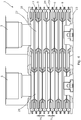
Fig. 7 shows another embodiment of theheat exchanger 1. The construction of theheat exchanger 1 is substantially identical with the one described above. In the present embodiment thechamber plates 9 are provided with a plurality ofembossments 32. Hence when the chamber plates are stacked in the predetermined process, theembossments 32 are configured to abut in theintermediate chamber 8 whereby the heat transfer through theintermediate chamber 8 is enhanced. Theembossments 32 furthermore provide structure to theheat exchanger 1. - In
Fig. 8a , thechamber plate 9 is shown in a top view. The plurality ofembossment 32 are provided in thechamber plate 9. Still, the chamber plate has the same configuration as described above in that inter alia provided with thefirst inlet 2, thefirst outlet 3, thesecond inlet 4 and thesecond outlet 5. In this view, thefirst rim section 16 is seen surrounding thesecond rim section 17, the first and second rim sections being separated by asafety passage 40. - In
Fig. 8b , a cross-sectional view taken along the line VIIIB ofFig. 8a is shown. Twochamber plates 9 are stacked in the predetermined manner having the plurality ofembossments 32. In the enlarged view, theembossments 32 of twoadjacent chamber plates 9 are abutting so that theintermediate chamber 8 is provided with enhanced heat transfer and structure. Furthermore, an enlarged view of the details of thechamber plates 9 near thesecond inlet 4 and thesecond outlet 5 is shown. It is shown that thesecond rim section 17 having a height h1 projects to the same level as thefirst rim section 16 having a lower height h2. Around thesecond rim section 17, asafety passage 40 is present. Hence, when a further set ofchamber plates 9 are placed on top of a first set ofchamber plates 9, the connection betweenfirst rim sections 16 and the connection of thesecond rim sections 17 are separated by thesafety passage 40. Therefore, if a leak should occur in either of the connections, the leak will flow into thesafety passage 40 and out. - The
embossments 32 are in the present embodiment shown as being herring-bone shaped. Other configurations of the embossments may be applied. - The first medium may be the medium which has to be treated, for instance cooled. The second medium may then be the heat transfer medium configured to cool the first medium.
- The dual media safety heat exchanger may in an embodiment be made as follows:
- providing a plurality of chamber plates being substantially identical,
- providing a first chamber plate,
- providing a second chamber plate,
- stacking the second chamber plate on top of the first chamber plate by arranging the second face of the first chamber plate opposite to the second face of the second chamber plate while aligning the first apertures of the first chamber plate with the second apertures of the second chamber plate,
- providing a third chamber plate,
- stacking the third chamber plate on top of the second chamber plate by arranging the first face of the third chamber plate opposite to the first face of the second chamber plate while aligning the second apertures of the second chamber plate with the second apertures of the third chamber plate,
- providing a fourth chamber plate,
- stacking the fourth chamber plate on top of the third chamber plate by arranging the second face of the third chamber plate opposite to the second face of the fourth chamber plate while aligning the first apertures of the third chamber plate with the second apertures of the fourth chamber plate,
- continuing stacking chamber plates in the same manner until a predetermined size of the heat exchanger is obtained, and
- connecting the chamber plates in a fluid tight manner providing the first medium chambers, the second medium chamber and the intermediate chambers.
- Advantageously, the connecting of the chamber plates may be performed by means of soldering.
- Although the invention has been described in the above in connection with preferred embodiments of the invention, it will be evident for a person skilled in the art that several modifications are conceivable without departing from the invention as defined by the following claims.
Claims (15)
- A dual media safety heat exchanger comprising- a first medium chamber configured to allow a first medium flow through the first medium chamber,- a second medium chamber configured to allow a second medium flow through the second medium chamber, and- an intermediate chamber arranged between the first medium chamber and the second medium chamber and being configured to separate the first medium chamber from the second medium chamber so that the first medium is prevented from being mixed with second medium or vice versa in the circumstance of a leak within the safety heat exchanger,- the first medium chamber, the second medium chamber and the intermediate chamber being arranged in a stacked manner,- the first medium chamber having a first inlet and a first outlet,- the second medium chamber having a second inlet and a second outlet,- the first medium chamber, the second medium chamber and the intermediate chamber being defined by a plurality of chamber plates having a configuration, wherein the configuration of each chamber plate is substantially identical irrespective of which chamber it is part of.
- A dual media safety heat exchanger according to claim 1, wherein the heat exchanger comprises a plurality of first medium chambers, a plurality of second medium chambers and a plurality of intermediate chambers, all being arranged in a stacked manner.
- A dual media safety heat exchanger according to claim 1 or 2, wherein the chamber plates are made from a blank material.
- A dual media safety heat exchanger according to claim 3, wherein the material is metal, preferably aluminium or any alloys thereof.
- A dual media safety heat exchanger according to any of the preceding claims, wherein the first inlet and the first outlet are extending through the stacked chamber plates and provide a first inlet channel and a first outlet channel being fluidly connected with the plurality of first medium chambers,
the second inlet and the second outlet are extending through the stacked chamber plates and provide a second inlet channel and a second outlet channel being fluidly connected with the plurality of second medium chambers. - A dual media safety heat exchanger according to claim 5, wherein the first inlet channel is configured to distribute the first medium to all the first medium chambers, and the second inlet channel is configured to distribute the second medium to all the second medium chambers.
- A dual media safety heat exchanger according to claim 5 or 6, wherein the first medium chambers are arranged in parallel in relation to the first inlet channel, and the second medium chambers are arranged in parallel in relation to the second inlet channel.
- A dual media safety heat exchanger according to any of the preceding claims, wherein embossments have been provided in the chamber plates, the embossments being herringbone-shaped.
- A dual media safety heat exchanger according to claim 5, wherein each chamber plate is substantially square-formed provided with four apertures at each corner, the apertures are configured to define the first inlet channel, the first outlet channel, the second inlet channel and the second outlet channel, respectively.
- A dual media safety heat exchanger according to claim 9, wherein the chamber plate has a centre axis, two of the apertures are arranged on a first side of the centre axis and the other two apertures are arranged on a second side of the centre axis, the second side being opposite side of the first side in relation to the centre axis.
- A dual media safety heat exchanger according to claim 9 and/or 10, wherein the two apertures arranged on the first side being the first apertures have a first diameter, the two apertures arranged on the second side being the second apertures have a second diameter, the first diameter being larger than the second diameter.
- A dual media safety heat exchanger according to any of the claims 9 to 11, wherein the chamber plate has a first face and a second face, first rim sections are provided around the first apertures, the first rim sections are projecting from the first face having a first distance, second rim sections are provided around the second apertures, the second rim sections are extending from the second face having a second distance.
- A dual media safety heat exchanger according to claim 12, wherein the second distance is larger than the first distance, preferably the second distance is at least twice the distance of the first distance.
- A dual media safety heat exchanger according to any of the preceding claims, wherein a first end plate is arranged on a first end of the stacked chamber plates, and a second end plate is arranged on a second end of the stacked chamber plates.
- A method for preparing a dual media safety heat exchanger according to any of the preceding claims, comprising- providing a plurality of chamber plates being substantially identical,- providing a first chamber plate,- providing a second chamber plate,- stacking the second chamber plate on top of the first chamber plate by arranging the second face of the first chamber plate opposite to the second face of the second chamber plate while aligning the first apertures of the first chamber plate with the second apertures of the second chamber plate,- providing a third chamber plate,- stacking the third chamber plate on top of the second chamber plate by arranging the first face of the third chamber plate opposite to the first face of the second chamber plate while aligning the second apertures of the second chamber plate with the second apertures of the third chamber plate,- providing a fourth chamber plate,- stacking the fourth chamber plate on top of the third chamber plate by arranging the second face of the third chamber plate opposite to the second face of the fourth chamber plate while aligning the first apertures of the third chamber plate with the second apertures of the fourth chamber plate,- continuing stacking chamber plates in the same manner until a predetermined size of the heat exchanger is obtained, and- connecting the chamber plates in a fluid tight manner providing the first medium chambers, the second medium chamber and the intermediate chambers.
Priority Applications (6)
| Application Number | Priority Date | Filing Date | Title |
|---|---|---|---|
| EP19177262.3A EP3745072A1 (en) | 2019-05-29 | 2019-05-29 | A dual media safety heat exchanger |
| EP20729690.6A EP3977034A1 (en) | 2019-05-29 | 2020-05-28 | A dual media safety heat exchanger |
| PCT/EP2020/064811 WO2020239894A1 (en) | 2019-05-29 | 2020-05-28 | A dual media safety heat exchanger |
| CN202080036084.8A CN113825969A (en) | 2019-05-29 | 2020-05-28 | Double-medium safety heat exchanger |
| US17/611,759 US20220228816A1 (en) | 2019-05-29 | 2020-05-28 | A dual media safety heat exchanger |
| TW109117864A TW202120877A (en) | 2019-05-29 | 2020-05-28 | A dual media safety heat exchanger |
Applications Claiming Priority (1)
| Application Number | Priority Date | Filing Date | Title |
|---|---|---|---|
| EP19177262.3A EP3745072A1 (en) | 2019-05-29 | 2019-05-29 | A dual media safety heat exchanger |
Publications (1)
| Publication Number | Publication Date |
|---|---|
| EP3745072A1 true EP3745072A1 (en) | 2020-12-02 |
Family
ID=66676361
Family Applications (2)
| Application Number | Title | Priority Date | Filing Date |
|---|---|---|---|
| EP19177262.3A Withdrawn EP3745072A1 (en) | 2019-05-29 | 2019-05-29 | A dual media safety heat exchanger |
| EP20729690.6A Pending EP3977034A1 (en) | 2019-05-29 | 2020-05-28 | A dual media safety heat exchanger |
Family Applications After (1)
| Application Number | Title | Priority Date | Filing Date |
|---|---|---|---|
| EP20729690.6A Pending EP3977034A1 (en) | 2019-05-29 | 2020-05-28 | A dual media safety heat exchanger |
Country Status (5)
| Country | Link |
|---|---|
| US (1) | US20220228816A1 (en) |
| EP (2) | EP3745072A1 (en) |
| CN (1) | CN113825969A (en) |
| TW (1) | TW202120877A (en) |
| WO (1) | WO2020239894A1 (en) |
Cited By (2)
| Publication number | Priority date | Publication date | Assignee | Title |
|---|---|---|---|---|
| EP4102170A1 (en) * | 2021-06-09 | 2022-12-14 | Danfoss A/S | Double plate heat exchanger |
| DE102022112039A1 (en) | 2022-05-13 | 2023-11-16 | Akg Verwaltungsgesellschaft Mbh | Safety heat exchanger |
Families Citing this family (3)
| Publication number | Priority date | Publication date | Assignee | Title |
|---|---|---|---|---|
| CN114413660A (en) * | 2021-12-14 | 2022-04-29 | 浙江银轮机械股份有限公司 | Heat exchanger |
| CN114413661A (en) * | 2021-12-14 | 2022-04-29 | 浙江银轮机械股份有限公司 | Heat exchanger |
| CN114413662A (en) * | 2021-12-14 | 2022-04-29 | 浙江银轮机械股份有限公司 | Heat exchanger |
Citations (5)
| Publication number | Priority date | Publication date | Assignee | Title |
|---|---|---|---|---|
| EP0252275A2 (en) * | 1986-07-03 | 1988-01-13 | W. Schmidt GmbH & Co. KG | Panel heat exchanger |
| EP1469270A1 (en) * | 2003-04-14 | 2004-10-20 | Peter Dipl.-Ing. Rehberg | Plate heat exchanger with double-walled heat exchanger plates |
| EP1526350A2 (en) * | 2003-10-21 | 2005-04-27 | Modine Manufacturing Company | Plate heat exchanger |
| EP1811255A2 (en) * | 2006-01-20 | 2007-07-25 | Flatplate, Inc. | Double-wall, vented heat exchanger |
| WO2018210392A1 (en) * | 2017-05-18 | 2018-11-22 | Underwood Christopher | Double wall printed circuit heat exchanger |
Family Cites Families (13)
| Publication number | Priority date | Publication date | Assignee | Title |
|---|---|---|---|---|
| US4678027A (en) * | 1984-12-14 | 1987-07-07 | Paul Mueller Company | Dual-walled coiled plate heat exchanger with vented interface |
| SE467275B (en) * | 1990-05-02 | 1992-06-22 | Alfa Laval Thermal Ab | FLOWED DOUBLE WALL PLATE HEAT EXCHANGER WITH BENDED EDGE |
| SE466027B (en) * | 1990-05-16 | 1991-12-02 | Alfa Laval Thermal Ab | DOUBLE WALL PLATE HEAT EXCHANGER WITH LEAKAGE CHANNELS TWO SEALING PARTS |
| US5469914A (en) * | 1993-06-14 | 1995-11-28 | Tranter, Inc. | All-welded plate heat exchanger |
| SE9502135D0 (en) * | 1995-06-13 | 1995-06-13 | Tetra Laval Holdings & Finance | plate heat exchangers |
| JP2001099587A (en) * | 1999-09-30 | 2001-04-13 | Hisaka Works Ltd | Plate type heat exchanger |
| SE516844C3 (en) * | 2000-07-07 | 2002-04-17 | Alfa Laval Ab | Plate heat / plate heat exchanger with electrically heated layers in double wall plate elements |
| US20110024095A1 (en) * | 2009-07-30 | 2011-02-03 | Mark Kozdras | Heat Exchanger with End Plate Providing Mounting Flange |
| CN102042772B (en) * | 2010-05-14 | 2013-03-06 | 南京工业大学 | Laminated board fin structured heat exchanger with medium equipartition device |
| US20160040943A1 (en) * | 2014-08-07 | 2016-02-11 | Kaori Heat Treatment Co., Ltd. | Heat exchanger |
| US20180073811A1 (en) * | 2016-09-12 | 2018-03-15 | Climate Master, Inc. | Double-wall heat exchanger |
| CN206609324U (en) * | 2016-12-21 | 2017-11-03 | 无锡宏盛换热器制造股份有限公司 | Plate type heat exchanger |
| CN111819415B (en) * | 2018-03-15 | 2022-09-27 | 三菱电机株式会社 | Plate heat exchanger, heat pump device provided with same, and heat pump type cooling/heating/water heating system provided with heat pump device |
-
2019
- 2019-05-29 EP EP19177262.3A patent/EP3745072A1/en not_active Withdrawn
-
2020
- 2020-05-28 CN CN202080036084.8A patent/CN113825969A/en active Pending
- 2020-05-28 US US17/611,759 patent/US20220228816A1/en active Pending
- 2020-05-28 TW TW109117864A patent/TW202120877A/en unknown
- 2020-05-28 WO PCT/EP2020/064811 patent/WO2020239894A1/en unknown
- 2020-05-28 EP EP20729690.6A patent/EP3977034A1/en active Pending
Patent Citations (5)
| Publication number | Priority date | Publication date | Assignee | Title |
|---|---|---|---|---|
| EP0252275A2 (en) * | 1986-07-03 | 1988-01-13 | W. Schmidt GmbH & Co. KG | Panel heat exchanger |
| EP1469270A1 (en) * | 2003-04-14 | 2004-10-20 | Peter Dipl.-Ing. Rehberg | Plate heat exchanger with double-walled heat exchanger plates |
| EP1526350A2 (en) * | 2003-10-21 | 2005-04-27 | Modine Manufacturing Company | Plate heat exchanger |
| EP1811255A2 (en) * | 2006-01-20 | 2007-07-25 | Flatplate, Inc. | Double-wall, vented heat exchanger |
| WO2018210392A1 (en) * | 2017-05-18 | 2018-11-22 | Underwood Christopher | Double wall printed circuit heat exchanger |
Cited By (3)
| Publication number | Priority date | Publication date | Assignee | Title |
|---|---|---|---|---|
| EP4102170A1 (en) * | 2021-06-09 | 2022-12-14 | Danfoss A/S | Double plate heat exchanger |
| US11933547B2 (en) | 2021-06-09 | 2024-03-19 | Danfoss A/S | Double plate heat exchanger |
| DE102022112039A1 (en) | 2022-05-13 | 2023-11-16 | Akg Verwaltungsgesellschaft Mbh | Safety heat exchanger |
Also Published As
| Publication number | Publication date |
|---|---|
| WO2020239894A1 (en) | 2020-12-03 |
| EP3977034A1 (en) | 2022-04-06 |
| TW202120877A (en) | 2021-06-01 |
| US20220228816A1 (en) | 2022-07-21 |
| CN113825969A (en) | 2021-12-21 |
Similar Documents
| Publication | Publication Date | Title |
|---|---|---|
| EP3745072A1 (en) | A dual media safety heat exchanger | |
| KR101129897B1 (en) | A plate heat exchanger | |
| US5392849A (en) | Layer-built heat exchanger | |
| US6142221A (en) | Three-circuit plate heat exchanger | |
| RU2606466C2 (en) | Plate of heat exchanger and plate heat exchanger containing such plate of heat exchanger | |
| KR101124874B1 (en) | Plate heat exchanger | |
| EP3115733B1 (en) | Heat exchange plate for plate-type heat exchanger and plate-type heat exchanger provided with said heat exchange plate | |
| US11060795B2 (en) | Double tube for heat exchange | |
| US11774191B2 (en) | Heat transfer plate and a plate pack for a heat exchanger comprising a plurality of such heat transfer plates | |
| EP3017261B1 (en) | Asymmetrical exchanger with ancillary channels for connecting turns | |
| EP0503080A1 (en) | Laminated heat exchanger | |
| EP3032208B1 (en) | Gasket groove for a plate heat exchanger | |
| US20110186274A1 (en) | Plate heat exchanger | |
| EP3816556A1 (en) | Heat exchanger | |
| EP3660436B1 (en) | Plate heat exchanger | |
| EP2990749B1 (en) | Heat exchanger | |
| RU2692857C1 (en) | Heat-transfer plate of plate-type heat exchanger and plate-type heat exchanger with such plate | |
| KR101987599B1 (en) | The plate heat exchanger of welding type | |
| CN216205611U (en) | Adapter for heat exchanger manifold | |
| US10876796B2 (en) | Heat exchanger | |
| KR101897927B1 (en) | The plate heat exchanger of welding type for high pressure condition | |
| WO2020059578A1 (en) | Plate stack and heat exchanger | |
| CN112361852B (en) | Printed circuit board heat exchanger | |
| EP3951305A1 (en) | Heat exchanger and heat exchange device | |
| KR20230061744A (en) | Printed circuit type heat exchanger |
Legal Events
| Date | Code | Title | Description |
|---|---|---|---|
| PUAI | Public reference made under article 153(3) epc to a published international application that has entered the european phase |
Free format text: ORIGINAL CODE: 0009012 |
|
| STAA | Information on the status of an ep patent application or granted ep patent |
Free format text: STATUS: THE APPLICATION HAS BEEN PUBLISHED |
|
| AK | Designated contracting states |
Kind code of ref document: A1 Designated state(s): AL AT BE BG CH CY CZ DE DK EE ES FI FR GB GR HR HU IE IS IT LI LT LU LV MC MK MT NL NO PL PT RO RS SE SI SK SM TR |
|
| AX | Request for extension of the european patent |
Extension state: BA ME |
|
| STAA | Information on the status of an ep patent application or granted ep patent |
Free format text: STATUS: THE APPLICATION IS DEEMED TO BE WITHDRAWN |
|
| 18D | Application deemed to be withdrawn |
Effective date: 20210603 |