EP3032083B1 - Cmc-oxid-oxid-mischerdesign - Google Patents
Cmc-oxid-oxid-mischerdesign Download PDFInfo
- Publication number
- EP3032083B1 EP3032083B1 EP15197419.3A EP15197419A EP3032083B1 EP 3032083 B1 EP3032083 B1 EP 3032083B1 EP 15197419 A EP15197419 A EP 15197419A EP 3032083 B1 EP3032083 B1 EP 3032083B1
- Authority
- EP
- European Patent Office
- Prior art keywords
- annulus
- shaft
- lobed
- exhaust
- leg
- Prior art date
- Legal status (The legal status is an assumption and is not a legal conclusion. Google has not performed a legal analysis and makes no representation as to the accuracy of the status listed.)
- Active
Links
Images



Classifications
-
- F—MECHANICAL ENGINEERING; LIGHTING; HEATING; WEAPONS; BLASTING
- F02—COMBUSTION ENGINES; HOT-GAS OR COMBUSTION-PRODUCT ENGINE PLANTS
- F02K—JET-PROPULSION PLANTS
- F02K1/00—Plants characterised by the form or arrangement of the jet pipe or nozzle; Jet pipes or nozzles peculiar thereto
- F02K1/46—Nozzles having means for adding air to the jet or for augmenting the mixing region between the jet and the ambient air, e.g. for silencing
-
- F—MECHANICAL ENGINEERING; LIGHTING; HEATING; WEAPONS; BLASTING
- F02—COMBUSTION ENGINES; HOT-GAS OR COMBUSTION-PRODUCT ENGINE PLANTS
- F02K—JET-PROPULSION PLANTS
- F02K1/00—Plants characterised by the form or arrangement of the jet pipe or nozzle; Jet pipes or nozzles peculiar thereto
- F02K1/38—Introducing air inside the jet
- F02K1/386—Introducing air inside the jet mixing devices in the jet pipe, e.g. for mixing primary and secondary flow
-
- F—MECHANICAL ENGINEERING; LIGHTING; HEATING; WEAPONS; BLASTING
- F01—MACHINES OR ENGINES IN GENERAL; ENGINE PLANTS IN GENERAL; STEAM ENGINES
- F01D—NON-POSITIVE DISPLACEMENT MACHINES OR ENGINES, e.g. STEAM TURBINES
- F01D25/00—Component parts, details, or accessories, not provided for in, or of interest apart from, other groups
- F01D25/28—Supporting or mounting arrangements, e.g. for turbine casing
-
- F—MECHANICAL ENGINEERING; LIGHTING; HEATING; WEAPONS; BLASTING
- F02—COMBUSTION ENGINES; HOT-GAS OR COMBUSTION-PRODUCT ENGINE PLANTS
- F02K—JET-PROPULSION PLANTS
- F02K1/00—Plants characterised by the form or arrangement of the jet pipe or nozzle; Jet pipes or nozzles peculiar thereto
- F02K1/78—Other construction of jet pipes
- F02K1/80—Couplings or connections
-
- F—MECHANICAL ENGINEERING; LIGHTING; HEATING; WEAPONS; BLASTING
- F01—MACHINES OR ENGINES IN GENERAL; ENGINE PLANTS IN GENERAL; STEAM ENGINES
- F01D—NON-POSITIVE DISPLACEMENT MACHINES OR ENGINES, e.g. STEAM TURBINES
- F01D25/00—Component parts, details, or accessories, not provided for in, or of interest apart from, other groups
- F01D25/24—Casings; Casing parts, e.g. diaphragms, casing fastenings
- F01D25/243—Flange connections; Bolting arrangements
-
- F—MECHANICAL ENGINEERING; LIGHTING; HEATING; WEAPONS; BLASTING
- F02—COMBUSTION ENGINES; HOT-GAS OR COMBUSTION-PRODUCT ENGINE PLANTS
- F02K—JET-PROPULSION PLANTS
- F02K1/00—Plants characterised by the form or arrangement of the jet pipe or nozzle; Jet pipes or nozzles peculiar thereto
- F02K1/46—Nozzles having means for adding air to the jet or for augmenting the mixing region between the jet and the ambient air, e.g. for silencing
- F02K1/48—Corrugated nozzles
-
- F—MECHANICAL ENGINEERING; LIGHTING; HEATING; WEAPONS; BLASTING
- F05—INDEXING SCHEMES RELATING TO ENGINES OR PUMPS IN VARIOUS SUBCLASSES OF CLASSES F01-F04
- F05D—INDEXING SCHEME FOR ASPECTS RELATING TO NON-POSITIVE-DISPLACEMENT MACHINES OR ENGINES, GAS-TURBINES OR JET-PROPULSION PLANTS
- F05D2230/00—Manufacture
- F05D2230/60—Assembly methods
- F05D2230/64—Assembly methods using positioning or alignment devices for aligning or centring, e.g. pins
- F05D2230/642—Assembly methods using positioning or alignment devices for aligning or centring, e.g. pins using maintaining alignment while permitting differential dilatation
-
- F—MECHANICAL ENGINEERING; LIGHTING; HEATING; WEAPONS; BLASTING
- F05—INDEXING SCHEMES RELATING TO ENGINES OR PUMPS IN VARIOUS SUBCLASSES OF CLASSES F01-F04
- F05D—INDEXING SCHEME FOR ASPECTS RELATING TO NON-POSITIVE-DISPLACEMENT MACHINES OR ENGINES, GAS-TURBINES OR JET-PROPULSION PLANTS
- F05D2250/00—Geometry
- F05D2250/60—Structure; Surface texture
- F05D2250/61—Structure; Surface texture corrugated
-
- F—MECHANICAL ENGINEERING; LIGHTING; HEATING; WEAPONS; BLASTING
- F05—INDEXING SCHEMES RELATING TO ENGINES OR PUMPS IN VARIOUS SUBCLASSES OF CLASSES F01-F04
- F05D—INDEXING SCHEME FOR ASPECTS RELATING TO NON-POSITIVE-DISPLACEMENT MACHINES OR ENGINES, GAS-TURBINES OR JET-PROPULSION PLANTS
- F05D2260/00—Function
- F05D2260/30—Retaining components in desired mutual position
-
- F—MECHANICAL ENGINEERING; LIGHTING; HEATING; WEAPONS; BLASTING
- F05—INDEXING SCHEMES RELATING TO ENGINES OR PUMPS IN VARIOUS SUBCLASSES OF CLASSES F01-F04
- F05D—INDEXING SCHEME FOR ASPECTS RELATING TO NON-POSITIVE-DISPLACEMENT MACHINES OR ENGINES, GAS-TURBINES OR JET-PROPULSION PLANTS
- F05D2260/00—Function
- F05D2260/96—Preventing, counteracting or reducing vibration or noise
-
- F—MECHANICAL ENGINEERING; LIGHTING; HEATING; WEAPONS; BLASTING
- F05—INDEXING SCHEMES RELATING TO ENGINES OR PUMPS IN VARIOUS SUBCLASSES OF CLASSES F01-F04
- F05D—INDEXING SCHEME FOR ASPECTS RELATING TO NON-POSITIVE-DISPLACEMENT MACHINES OR ENGINES, GAS-TURBINES OR JET-PROPULSION PLANTS
- F05D2300/00—Materials; Properties thereof
- F05D2300/60—Properties or characteristics given to material by treatment or manufacturing
- F05D2300/603—Composites; e.g. fibre-reinforced
- F05D2300/6033—Ceramic matrix composites [CMC]
Definitions
- An improved exhaust mixing system is disclosed. Although the improvements are applicable to exhaust mixing systems for turbine engines used for propulsive power in air, the improvements are also applicable to exhaust mixing systems for turbine engines employed in marine, underwater, and land applications.
- an exhaust mixing system according to the features of claim 1, and a method of manufacturing an exhaust mixing system according to the method steps of claim 9.
- the mixing system includes an attachment system for securing a lobed mixer to an engine interface.
- a novel method of manufacturing an exhaust mixing system is further disclosed.
- Figure 1 illustrates an exemplary gas turbine engine 10, which includes a fan 12, a low pressure compressor and a high pressure compressor, 14 and 16, a combustor 18, and a high pressure, mid pressure and low pressure turbine, 20, 21 and 22, respectively.
- the high pressure compressor 16 is connected to a first rotor shaft 24 while the low pressure compressor 14 is connected to a second rotor shaft 26.
- the low pressure turbine 22 is connected to another shaft 27.
- the shafts extend axially and are parallel to a longitudinal center line axis 28.
- Figure 1 illustrates a three shaft engine, it will be appreciated that exemplary embodiments further contemplate two shaft and/or single shaft configurations.
- Ambient air 30 enters the fan 12 and is directed across a fan rotor 32 in an annular duct 34, which in part is circumscribed by fan case 36.
- the bypass airflow 38 provides a large fraction of engine thrust while the primary gas stream 40 (a.k.a. core airflow) is directed to the combustor 18 and the turbines 20, 21, 22, and then exhausted through a nozzle generating thrust.
- the engine 10 includes an improved exhaust mixing system 44.
- the system 44 may include a lobed mixer 46 which can be coupled to an engine interface or support 48 (e.g., rear turbine support).
- the exhaust mixing system 44 enhances the mixing of the core airflow 40 that passes through the low pressure turbine 22 with the bypass airflow 38 that passes over the lobed mixer 46, thus increasing thrust.
- the mixing of the core airflow 40 and the bypass airflow 38, while each pass over a tail cone 50 and exit at exhaust nozzle 52, may also reduce turbine noise.
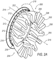
- the exhaust mixing system 200 includes a lobed exhaust mixer 204 and coupling attachment or flange 206, which couples the lobed exhaust mixer 200 to the engine interface 202.
- the lobed exhaust mixer 204 may, for example, be comprised of a single unit that circumscribes 360 degrees. Alternatively, though not shown, the lobed exhaust mixer 204 may be comprised of two or more semi-annular components that together circumscribe 360 degrees.
- the lobed exhaust mixer 204 is fabricated from, for example, ceramic matrix composite (CMC) materials, such as high strength ceramics alumina fibers in an alumina oxide composite matrix. Alternate embodiments may include other CMC materials such as alumino-silicate fibers in a ceramic matrix. Regardless of the CMC materials employed, the CMC lobed exhaust mixer 204 includes a plurality of lobes 208 that enhance mixing of core airflow and bypass airflow in such a manner to increase thrust and decrease engine noise. According to alternate embodiments, the number of lobes of the CMC lobed exhaust mixer may be more or less than the number of lobes illustrated in Figure 2A .
- CMC ceramic matrix composite
- the CMC lobed exhaust mixer 204 is configured to mix generally warm or hot core airflow (e.g., primary gas stream 40 of Figure 1 ) with cooler bypass flow (e.g., bypass airflow 38 of Figure 1 ) via the plurality of lobes 208, Figure 2A .
- the mixing of the two airflows by the CMC lobed exhaust mixer 204 generally increases thrust when compared to exhaust systems (not shown) that are not configured to mix, or to enhance the mixture of, core airflow and bypass airflow.
- the mixing of the core and bypass airflows enhanced by the plurality of lobes 208 may decrease jet induced noise.
- Structures comprised of CMC materials generally weigh less than similar structures comprised of metallic materials. Further, structures comprised of CMC materials also tend to outperform many comparable metallic structures in their ability to maintain structural shape at higher temperatures. As such, the CMC lobed exhaust mixer 204 generally weighs less and is more durable than comparable mixers comprised of metallic materials. The reduction of weight, in turn, generally enhances fuel efficiencies of the turbofan engine (e.g., gas turbine engine 10 of Figure 1 ).
- the coupling attachment or flange 206 of the exhaust system 200 includes an annulus or coupling ring 210 having a plurality of projections (a.k.a. finger couplings) 212 extending linearly therefrom.
- the coupling attachment 206 may, for example, be comprised of a metal alloy or super alloy such as Inconel® 625. Further, the coupling attachment 206 may be a single fabricated unit circumscribing 360 degrees or, alternatively, the coupling attachment 206 may be comprised of a plurality of semi-annular components that together circumscribe 360 degrees.
- the plurality of projections 212 of the coupling attachment 206 project from the annulus 210 in a first direction 214 that is substantially parallel to a central axis 216 of the annulus 210.
- the coupling attachment 206 couples the CMC lobed exhaust mixer 204 to an engine support or interface 202 of a turbofan engine (alternatively see, e.g., support 48 of engine 10 illustrated in Figure 1 ). That is, as illustrated in Figure 2A , the annulus 210 of the coupling attachment 206 couples to the engine interface 202, while the plurality of projections 212 of the coupling attachment 206 couples to the CMC lobed exhaust mixer 204.
- Each projection of the plurality of projections 212 has the ability to flex. As such, the plurality of projections or finger couplings 212 maintain integrity when the CMC lobed exhaust mixer 204 is subjected to a range aerodynamic or thermal loads.
- the quantity of projections in the plurality of projections 212 is proportional to the quantity of lobes in the CMC lobed exhaust mixer 204. For example, there may be two to four times as many projections 212 as there are lobes 208. It is noted, however, that there need not be a 2:1, 3:1, or 4:1 relationship between the number of projections and the number of lobes. For example, based on weight and/or size factors of the CMC lobed mixer (e.g., CMC lobed exhaust mixer 204), fewer or more projection may be employed.
- the coupling attachment 206 In addition to coupling the CMC lobed exhaust mixer 204 to the engine (e.g., engine 10 of Figure 1 ), the coupling attachment 206 also serves to reduce stress on the system minimizing structural deflections to the mixer lobes. That is, load is able to pass from the support 202, through coupling attachment 206, and to CMC lobed exhaust mixer 204 without causing (or at least by minimizing) local or structural stresses on the system. Since the coupling attachment 206 has the ability to flex, it serves as an intermediary between the rear turbine support 202 and the CMC lobed exhaust mixer 204.
- FIG. 2B a cross-sectional view of a portion 218 of the exemplary exhaust mixing system 200 of Figure 2A is illustrated.
- the annulus 210 is coupled to the engine interface or rear turbine support 202 via a plurality of annulus mounting hardware 220.
- each projection of the plurality of projections 212 couples to the CMC lobed exhaust mixer 204 via a plurality of projection mounting hardware 222.
- the mounting means or hardware 220, 222 may, for example, include machined bolts and nuts or other fasteners (not shown).
- the portion of the exhaust mixing system 300 includes a portion of a coupling means or attachment 302 (a.k.a. attachment flange) and a portion of a CMC lobed exhaust mixer 304.
- the partial coupling attachment 302 includes a portion of an annulus 306 having a finger coupling 308 projecting linearly therefrom along a first direction 310.
- the annulus 306 affixes to an engine interface 312 and the finger coupling 308 affixes to the CMC lobed exhaust mixer 304, thus coupling the exhaust mixing system 300 to the turbine engine (e.g., engine 10 of Figure 1 ).
- the annulus 306 includes a first leg 314 in union with a second leg 316.
- the second leg 316 is substantially perpendicular to the first leg 314, while the first leg 314 is substantially parallel with the first direction 310.
- the finger coupling 308 includes a void 318 that aligns with a void 320 in the CMC lobed exhaust mixer 304.
- a fastener or mounting hardware e.g., the plurality of projection mounting hardware 222 of Figure 2B
- the annulus 306 includes a plurality of voids (see exemplary annulus void 332), which allow mounting hardware (e.g., plurality of annulus mounting hardware 220 of Figure 2B ) to pass therethrough so that the annulus 306 may be coupled to the engine interface 312.
- the exhaust mixing system 300 is coupled to an engine (e.g., engine 10 of Figure 1 ).
- finger couplings e.g., finger coupling 308
- the manner in which the CMC lobed exhaust mixer 304 is coupled to the engine interface 312 loads due to aerodynamic pressure and thermal growth are reduced and substantially in shear.
- the finger coupling 308 has a finger length 324 of L 1 , a head length 326 of L 2 , a shaft width 328 of W 1 , a head width 330 of W 2 , a shaft thickness 332 of T 1 , and a head thickness 334 of T 2 .
- finger coupling dimensions may fall within the following guidelines: finger length 324 (L 1 ) is four to six times the dimension of the shaft width 328 (W 1 ); the head thickness 334 (T 2 ) is two to three times the dimension of the shaft thickness 332 (T 1 ); the shaft width 328 is one to 1.3 times the dimension of the head width 330 (W 2 ); and the shaft thickness 332 (T 1 ) is approximately 0.10 times the dimension of the shaft width 328 (W 1 ). Finger couplings manufactured within these guidelines enhance the couplings ability to flex, thus enhancing the coupling attachment's 302 ability to operate through a range of aerodynamic or thermal loads.
- the exhaust mixing system 300 of Figure 3B includes a set of finger mounting hardware 336 (a.k.a. projection mounting hardware).
- the finger mounting hardware 336 includes a flat head bolt 338 that passes through the CMC lobed exhaust mixer 304 and a head 340 of the finger coupling 308.
- the finger mounting hardware 336 also includes a nut 342 that, in conjunction with the flat head bolt 338, affixes the finger coupling 308 to the CMC lobed exhaust mixer 304.
- the finger mounting hardware 336 depicted in Figure 3B includes the nut 342 and the flat head bolt 338, embodiments (not shown) employing other mounting hardware or fastening systems are envisioned.
- a thickness 348 (T 3 ) at a mounting region 350 of the CMC lobed exhaust mixer 304 is greater than a thickness 352 (T 4 ) at the first edge 354 of the CMC lobed exhaust mixer 304.
- the increased thickness 348 (T 3 ) adds integrity to the CMC lobed exhaust mixer 304 where the mounting region 350 meets the head 340 of the finger coupling 308.
- a flowchart 400 represents an exemplary method of manufacturing an exhaust mixing system, (e.g., exhaust mixing system 44 of Figure 1 , exhaust mixing system 200 of Figures 2A-2B , and/or exhaust mixing system 300 of Figures 3A-3B ).
- Process control begins at block 402, where the method includes forming a ring having a first leg and a second leg substantially perpendicular to the first leg. Process control then proceeds to block 404, where the method further includes forming a plurality of coupling fingers projecting from the second leg of the ring in a direction substantially parallel to the first leg. Together, the ring and the plurality of coupling fingers form an annular lobed mixer attachment flange. It is contemplated that the ring and coupling fingers may be formed as separate features and then later joined. As such, forming of the coupling fingers may occur prior to, or at the same time as, the forming of the ring. Alternatively, a mold may be employed to fabricate the attachment flange with the ring and coupling fingers as a single unit (or a plurality of semi-annular units).
- process control proceeds to block 406, where the method of manufacturing includes fabricating a CMC lobed mixer.
- the flowchart 400 depicts the fabrication of the CMC lobed mixer (i.e., block 406) occurring prior to the fabrication of the attachment flange (i.e., block 402, 404)
- alternate methods of manufacture may fabricate the CMC mixer prior to, or at the same time as, the fabrication off the attachment flange.
- the Oxide-Oxide CMC mixer may be formed or shaped as a laminate. The laminate process is similar to a process that employs polymer composites, except it is sintered at high temperature and trimmed to design.
- process control proceeds to block 408, where the method includes affixing the CMC lobed mixer to each coupling finger of the plurality of coupling fingers.
- the CMC lobed mixer is coupled to each coupling finger in such a manner to ensure that the CMC lobed mixer does not come in contact with the ring of the attachment flange. That is, the CMC lobed mixer is affixed to the attachment flange such that there is a gap between an upstream end of the CMC lobed mixer and the ring of the attachment flange. It is contemplated that this gap allows for thermal growth of the lobed mixer and/or attachment flange. Accordingly, the possibility of the CMC lobed mixer coming in contact with the ring of the attachment flange during normal high temperature operation is at least minimized.
- process control proceeds to block 410, where the method includes affixing the second leg of the attachment flange ring to an engine interface (e.g., a rear turbine support).
- the engine interface is an interface employed to couple the exhaust mixer system (i.e., the CMC lobed mixer and the attachment flange) to the turbofan engine.
- the CMC lobed mixer and attachment flange are coupled to a turbofan engine via the engine interface.
- the attachment flange serves as an intermediary between the engine interface and the CMC lobed mixer and, as such, allows loads to pass through the system while minimizing local stresses. It is noted that rivets, nuts and bolts, and/or another type of fastener may be used to fasten the attachment flange to the engine interface.
- Process control then proceeds to an end after affixing the ring to the engine interface.
- the attachment flange may be attached to the engine interface prior to, or at the same time as, attachment of the CMC lobed mixer to the attachment flange.
Landscapes
- Engineering & Computer Science (AREA)
- Mechanical Engineering (AREA)
- General Engineering & Computer Science (AREA)
- Chemical & Material Sciences (AREA)
- Combustion & Propulsion (AREA)
- Exhaust Silencers (AREA)
- Exhaust Gas After Treatment (AREA)
- Materials Engineering (AREA)
Claims (14)
- Abgasmischsystem (44, 200, 300) eines Turbinentriebwerks (10), wobei das Abgasmischsystem (44, 200, 300) umfasst:einen gelappten Abgasmischer (204, 304) und einen Befestigungsflansch (206, 302), der so ausgestaltet ist, dass er den gelappten Abgasmischer (204, 304) an das Turbinentriebwerk (10) koppelt, wobei der Befestigungsflansch (206, 302) umfasst:einen Ring (210, 306), der so ausgestaltet ist, dass er sich an das Turbinentriebwerk (10) koppelt; undeine Mehrzahl von Vorsprüngen (212, 308), die sich von dem Ring (210, 306) aus entlang einer ersten Richtung (214, 310) zu dem gelappten Abgasmischer (204, 304) hin und im Wesentlichen parallel zu einer Mittelachse (216) des Rings (210, 306) erstreckt, wobei jeder der Mehrzahl von Vorsprüngen (212, 308) einen Schaft, der sich von dem Ring (210, 306) aus erstreckt, und einen Kopf, mittels dessen jeder der Mehrzahl von Vorsprüngen (212, 308) so ausgestaltet ist, dass er sich an den gelappten Abgasmischer (204, 304) koppelt, beinhaltet, wobei der Kopf eine Kopfdicke (334) aufweist, die, gemessen in einer radialen Richtung des Rings (210, 306), größer als eine Schaftdicke (332) des Schaftes ist; undwobei der gelappte Abgasmischer (204, 304) aus einem Keramik-Matrix-Verbundwerkstoff zusammengesetzt ist.
- Abgasmischsystem (44, 200, 300) nach Anspruch 1, wobei der Ring (210, 306) umfasst:einen ersten Schenkel (314), von dem aus sich die Mehrzahl von Vorsprüngen (212, 308) erstreckt; undeinen zweiten Schenkel (316) in Verbindung mit dem ersten Schenkel (314).
- Abgasmischsystem (44, 200, 300) nach Anspruch 2, wobei der erste Schenkel (314) im Wesentlichen lotrecht zu dem zweiten Schenkel (316) verläuft.
- Abgasmischsystem (44, 200, 300) nach einem der Ansprüche 1 bis 3, wobei der Ring (210, 306) aus einer Mehrzahl von Halbringen zusammengesetzt ist.
- Abgasmischsystem (44, 200, 300) nach einem der vorangehenden Ansprüche, wobei eine Gesamtzahl von Vorsprüngen (212, 308) in der Mehrzahl von Vorsprüngen (212, 308) mindestens das Doppelte einer Gesamtzahl von Lappen (208) in dem gelappten Abgasmischer (204, 304) beträgt.
- Abgasmischsystem (44, 200, 300) nach einem der vorangehenden Ansprüche, wobei der Befestigungsflansch (206, 302) aus einer Superlegierung zusammengesetzt ist.
- Abgasmischsystem (44, 200, 300) nach einem der vorangehenden Ansprüche, wobei:eine Länge (324) jedes der Mehrzahl von Vorsprüngen (212, 308) vier- bis sechsmal größer als eine Schaftbreite (328) des Schaftes, gemessen in einer Umfangsrichtung des Rings (210, 306), ist; oder/unddie Kopfdicke (334) zwei- bis dreimal größer als die Schaftdicke (332) ist; oder/unddie Schaftbreite (328) ein- bis 1,3-mal größer als eine Kopfbreite (330) des Kopfes, gemessen in einer Umfangsrichtung des Rings (210, 306), ist; oder/unddie Schaftdicke (332) ca. 0,10-mal kleiner als die Schaftbreite (328) ist.
- Abgasmischsystem (44, 200, 300) nach einem der vorangehenden Ansprüche, wobei jeder Vorsprung (212, 308) der Mehrzahl von Vorsprüngen (212, 308) einen Hohlraum (318) an einem Ende beinhaltet, der so ausgestaltet ist, dass er ermöglicht, dass Montagekleinteile (220, 222, 336) durch ihn hindurch zu dem gelappten Abgasmischer (204, 304) gehen, um jeden Vorsprung (212, 308) an den gelappten Abgasmischer (204, 304) zu koppeln.
- Verfahren (400) zur Herstellung eines Abgasmischsystems (44, 200, 300) nach Anspruch 1, umfassend:
Fertigen (402, 404) des Befestigungsflansches (206, 302), wobei das Fertigen des Befestigungsflansches (206, 302) umfasst:Bilden (402) des Rings (210, 306) mit einem ersten Schenkel (314) und einem zweiten Schenkel (316), der im Wesentlichen lotrecht zu dem ersten Schenkel (314) verläuft; undBilden (404) der Mehrzahl von Vorsprüngen (212, 308), die jeweils einen Schaft, der von dem zweiten Schenkel (316) in einer im Wesentlichen parallel zu dem ersten Schenkel (314) verlaufenden Richtung (214, 310) vorspringt, und einen Kopf an einem dem zweiten Schenkel gegenüber liegenden Ende des Schaftes aufweisen, wobei der Kopf eine Dicke (334) aufweist, die größer als eine Dicke (332) des Schaftes ist. - Verfahren (400) zur Herstellung nach Anspruch 9, ferner umfassend das Fertigen (406) eines gelappten Abgasmischers (204, 304), der so ausgestaltet ist, dass er das Mischen eines Nebenluftstroms (38) mit einem Kernluftstrom (40) verbessert, wobei der gelappte Abgasmischer (204, 304) eine Mehrzahl von Lappen (208) umfasst.
- Verfahren (400) zur Herstellung nach Anspruch 10, ferner umfassend das Befestigen (410) des zweiten Schenkels (316) des Rings (210, 306) an einer Triebwerksanschlussstelle (202, 312), um den Befestigungsflansch (206, 302) an ein Turbofantriebwerk (10) zu koppeln.
- Verfahren (400) zur Herstellung nach Anspruch 10 oder 11,
wobei das Bilden (404) der Vorsprünge (212, 308) das Bilden von zwei- bis viermal so vielen Vorsprüngen (212, 308) umfasst, wie Lappen (208) in der Mehrzahl von Lappen (208) vorhanden sind. - Verfahren (400) nach einem der Ansprüche 10 bis 12, wobei:eine Länge (324) jedes der Mehrzahl von Vorsprüngen (212, 308) vier- bis sechsmal größer als eine Schaftbreite (328) des Schaftes, gemessen in einer Umfangsrichtung des Rings (210, 306), ist; oder/unddie Kopfdicke (334) zwei- bis dreimal größer als die Schaftdicke (332), gemessen in einer radialen Richtung des Rings (210, 306), ist; oder/unddie Schaftbreite (328) ein- bis 1,3-mal größer als eine Kopfbreite (330) des Kopfes, gemessen in einer Umfangsrichtung des Rings (210, 306), ist; oder/unddie Schaftdicke (332) ca. 0,10-mal kleiner als die Schaftbreite (328) ist.
- Verfahren (400) zur Herstellung nach Anspruch 13, wobei das Befestigen (408) des gelappten Abgasmischers (204, 304) an jedem Vorsprung (212, 308) der Mehrzahl von Vorsprüngen (212, 308) das Befestigen des gelappten Abgasmischers (204, 304) an jedem Vorsprung (212, 308) derart, dass eine Lücke (344) zwischen dem gelappten Abgasmischer (204, 304) und dem zweiten Schenkel (316) des Rings (210, 306) vorhanden ist, umfasst.
Applications Claiming Priority (1)
| Application Number | Priority Date | Filing Date | Title |
|---|---|---|---|
| US201462089452P | 2014-12-09 | 2014-12-09 |
Publications (2)
| Publication Number | Publication Date |
|---|---|
| EP3032083A1 EP3032083A1 (de) | 2016-06-15 |
| EP3032083B1 true EP3032083B1 (de) | 2019-05-22 |
Family
ID=54834626
Family Applications (1)
| Application Number | Title | Priority Date | Filing Date |
|---|---|---|---|
| EP15197419.3A Active EP3032083B1 (de) | 2014-12-09 | 2015-12-02 | Cmc-oxid-oxid-mischerdesign |
Country Status (3)
| Country | Link |
|---|---|
| US (2) | US10451001B2 (de) |
| EP (1) | EP3032083B1 (de) |
| CN (1) | CN105697193B (de) |
Families Citing this family (16)
| Publication number | Priority date | Publication date | Assignee | Title |
|---|---|---|---|---|
| US10451001B2 (en) * | 2014-12-09 | 2019-10-22 | Rolls-Royce Corporation | CMC oxide-oxide mixer design |
| DE102016217033A1 (de) | 2016-09-07 | 2018-03-08 | Rolls-Royce Deutschland Ltd & Co Kg | Mischerbaugruppe für ein Turbofan-Triebwerk |
| DE102016222583A1 (de) | 2016-11-16 | 2018-05-17 | Rolls-Royce Deutschland Ltd & Co Kg | Mischer für ein Triebwerk hergestellt aus mindestens einem Verbundwerkstoff, Herstellungsverfahren und Herstellungsvorrichtung |
| FR3061749B1 (fr) * | 2017-01-11 | 2020-05-01 | Safran Aircraft Engines | Melangeur de flux a epaisseur evolutive |
| US11118481B2 (en) | 2017-02-06 | 2021-09-14 | Raytheon Technologies Corporation | Ceramic matrix composite turbine exhaust assembly for a gas turbine engine |
| US10738649B2 (en) * | 2017-08-03 | 2020-08-11 | Rolls-Royce Corporation | Reinforced oxide-oxide ceramic matrix composite (CMC) component and method of making a reinforced oxide-oxide CMC component |
| FR3084397B1 (fr) * | 2018-07-24 | 2021-04-16 | Safran Aircraft Engines | Carter de turbine basse pression a ensemble de protection contre des chocs |
| US10895170B2 (en) * | 2018-10-22 | 2021-01-19 | Raytheon Technologies Corporation | Shear wave resistant flange assembly |
| CN110454298A (zh) * | 2019-07-26 | 2019-11-15 | 中国航发沈阳发动机研究所 | 一种具有降噪功能的排气装置 |
| US11180421B2 (en) | 2019-09-04 | 2021-11-23 | Rolls-Royce Corporation | Repair and/or reinforcement of oxide-oxide CMC |
| CN111536555A (zh) * | 2020-05-08 | 2020-08-14 | 中国航发湖南动力机械研究所 | 发动机及其发动机燃烧室 |
| CN111981510A (zh) * | 2020-07-31 | 2020-11-24 | 中国航发贵阳发动机设计研究所 | 一种可产生有旋射流的波瓣混合器 |
| US20220161205A1 (en) * | 2020-11-20 | 2022-05-26 | Pratt & Whitney Canada Corp. | Exhaust mixer |
| CN113102868B (zh) * | 2021-04-20 | 2023-02-28 | 中国直升机设计研究所 | 一种直升机主喷管波瓣加工方法 |
| CN113586281B (zh) * | 2021-07-15 | 2022-08-02 | 哈尔滨工程大学 | 一种带非均匀波瓣引射混合器的船舶燃气轮机 |
| CN115875153B (zh) * | 2022-12-27 | 2026-03-17 | 西安鑫垚陶瓷复合材料股份有限公司 | 一种用于安装陶瓷基复合材料混合器的弹性法兰装置 |
Family Cites Families (28)
| Publication number | Priority date | Publication date | Assignee | Title |
|---|---|---|---|---|
| GB2114229B (en) | 1981-11-03 | 1984-11-21 | Rolls Royce | Gas turbine engine infra-red radiation suppressor |
| US4662658A (en) * | 1984-06-04 | 1987-05-05 | General Electric Company | Seal |
| FR2623249A1 (fr) | 1987-11-12 | 1989-05-19 | Snecma | Ensemble constitue de deux pieces en materiaux ayant des coefficients de dilatation differents, reliees entre elles et methode d'assemblage |
| EP0635632B1 (de) * | 1993-06-25 | 1997-10-22 | THE NORDAM GROUP, Inc. | System zur Schalldämpfung |
| EP1141534B1 (de) | 1999-01-04 | 2005-04-06 | Allison Advanced Development Company | Abgasmischvorrichtung und gerät mit einer solchen vorrichtung |
| US20050097893A1 (en) | 2003-11-07 | 2005-05-12 | General Electric Company | Method and apparatus for increasing a durability of a body |
| FR2875854B1 (fr) | 2004-09-29 | 2009-04-24 | Snecma Propulsion Solide Sa | Melangeur pour tuyere a flux separes |
| US8049293B2 (en) * | 2005-03-07 | 2011-11-01 | Sony Corporation | Solid-state image pickup device, electronic apparatus using such solid-state image pickup device and method of manufacturing solid-state image pickup device |
| FR2891272B1 (fr) | 2005-09-28 | 2009-07-10 | Snecma Sa | Procede de protection contre l'usure d'une piece thermostructurale en materiau composite a matrice ceramique, revetement et piece obtenus par ce procede. |
| US7546743B2 (en) * | 2005-10-12 | 2009-06-16 | General Electric Company | Bolting configuration for joining ceramic combustor liner to metal mounting attachments |
| US8141370B2 (en) * | 2006-08-08 | 2012-03-27 | General Electric Company | Methods and apparatus for radially compliant component mounting |
| FR2912469B1 (fr) * | 2007-02-12 | 2009-05-08 | Snecma Propulsion Solide Sa | Procede de fabrication d'une structure a lobes de melangeur de flux en cmc pour moteur aeronautique a turbine de gaz. |
| FR2914955B1 (fr) * | 2007-04-10 | 2009-07-10 | Snecma Propulsion Solide Sa | Melangeur en cmc a capotage externe structural |
| US8726665B2 (en) * | 2007-06-05 | 2014-05-20 | The Boeing Company | Internal mixing of a portion of fan exhaust flow and full core exhaust flow in aircraft turbofan engines |
| US8726675B2 (en) * | 2007-09-07 | 2014-05-20 | The Boeing Company | Scalloped flexure ring |
| FR2935753B1 (fr) | 2008-09-08 | 2011-07-01 | Snecma Propulsion Solide | Liaisons souples a butee pour fixation de piece en cmc |
| FR2949820B1 (fr) | 2009-09-04 | 2011-10-14 | Aircelle Sa | Ensemble structurant pour une tuyere d'ejection. |
| US9938900B2 (en) | 2011-05-26 | 2018-04-10 | United Technologies Corporation | Ceramic matrix composite turbine exhaust case for a gas turbine engine |
| US9021813B2 (en) | 2011-07-18 | 2015-05-05 | The Boeing Company | Cable-actuated variable area fan nozzle with elastomeric seals |
| CN104379918B (zh) * | 2012-04-27 | 2017-12-12 | 通用电气公司 | 燃气涡轮发动机的混合器及其制造方法、燃气涡轮发动机 |
| WO2013163510A1 (en) * | 2012-04-27 | 2013-10-31 | General Electric Company | Connecting gas turbine engine annular members |
| FR2992353B1 (fr) * | 2012-06-21 | 2016-12-30 | Snecma | Ensemble forme d'un cone d'echappement et d'un carter d'echappement dans un moteur a turbine a gaz |
| FR2994712B1 (fr) | 2012-08-27 | 2018-04-13 | Safran Aircraft Engines | Procede d'assemblage d'une tuyere et d'un carter d'echappement d'une turbomachine |
| US9188024B2 (en) | 2013-02-22 | 2015-11-17 | Pratt & Whitney Canada Corp. | Exhaust section for bypass gas turbine engines |
| US9732701B2 (en) * | 2014-05-12 | 2017-08-15 | Rohr, Inc. | Center body attachment system |
| FR3028294B1 (fr) * | 2014-11-06 | 2020-06-12 | Safran Aircraft Engines | Carenage pour melangeur de tuyere de turbomachine a double flux |
| US9784215B2 (en) * | 2014-11-07 | 2017-10-10 | Rohr, Inc. | Exhaust nozzle center body attachment |
| US10451001B2 (en) * | 2014-12-09 | 2019-10-22 | Rolls-Royce Corporation | CMC oxide-oxide mixer design |
-
2015
- 2015-11-20 US US14/947,210 patent/US10451001B2/en active Active
- 2015-12-02 EP EP15197419.3A patent/EP3032083B1/de active Active
- 2015-12-08 CN CN201510896741.7A patent/CN105697193B/zh not_active Expired - Fee Related
-
2019
- 2019-09-09 US US16/564,966 patent/US20190390631A1/en not_active Abandoned
Non-Patent Citations (1)
| Title |
|---|
| None * |
Also Published As
| Publication number | Publication date |
|---|---|
| US10451001B2 (en) | 2019-10-22 |
| US20190390631A1 (en) | 2019-12-26 |
| CN105697193B (zh) | 2020-08-21 |
| EP3032083A1 (de) | 2016-06-15 |
| CN105697193A (zh) | 2016-06-22 |
| US20160160690A1 (en) | 2016-06-09 |
Similar Documents
| Publication | Publication Date | Title |
|---|---|---|
| EP3032083B1 (de) | Cmc-oxid-oxid-mischerdesign | |
| EP2546574B1 (de) | Brennkammerschaufelringanordnung aus keramischem Matrixverbundstoff | |
| EP2255086B1 (de) | Platten- und ring-cmc-düse | |
| US10100664B2 (en) | Ceramic centerbody and method of making | |
| US20120275922A1 (en) | High area ratio turbine vane | |
| CN108868902B (zh) | 具有共同结合复合材料和金属环的部件及其组装方法 | |
| CN110621850B (zh) | 复合翼型单体以及单体的相应组件 | |
| US12196131B2 (en) | Gas turbine engine | |
| EP3913197B1 (de) | Anordnungen zur übertragung von druckbelastungen in flanschen von gasturbinenbauteilen aus verbundwerkstoff | |
| CN107120690B (zh) | 燃烧器组件 | |
| US20250369395A1 (en) | Gas turbine engine | |
| US11112119B2 (en) | Combustor assembly for a turbo machine | |
| US11280202B2 (en) | Balanced composite root region for a blade of a gas turbine engine | |
| US20190170013A1 (en) | Discontinuous Molded Tape Wear Interface for Composite Components | |
| CA2955538C (en) | Flowpath assembly for a gas turbine engine | |
| US12304177B2 (en) | Ceramic matrix composite (CMC) component resistant to edge cracks | |
| US12398660B2 (en) | Systems and methods for attachment of materials having different thermal expansion coefficients | |
| EP3771804B1 (de) | Abgasgehäuse eines gasturbinentriebwerks |
Legal Events
| Date | Code | Title | Description |
|---|---|---|---|
| PUAI | Public reference made under article 153(3) epc to a published international application that has entered the european phase |
Free format text: ORIGINAL CODE: 0009012 |
|
| AK | Designated contracting states |
Kind code of ref document: A1 Designated state(s): AL AT BE BG CH CY CZ DE DK EE ES FI FR GB GR HR HU IE IS IT LI LT LU LV MC MK MT NL NO PL PT RO RS SE SI SK SM TR |
|
| AX | Request for extension of the european patent |
Extension state: BA ME |
|
| STAA | Information on the status of an ep patent application or granted ep patent |
Free format text: STATUS: REQUEST FOR EXAMINATION WAS MADE |
|
| 17P | Request for examination filed |
Effective date: 20161125 |
|
| RBV | Designated contracting states (corrected) |
Designated state(s): AL AT BE BG CH CY CZ DE DK EE ES FI FR GB GR HR HU IE IS IT LI LT LU LV MC MK MT NL NO PL PT RO RS SE SI SK SM TR |
|
| STAA | Information on the status of an ep patent application or granted ep patent |
Free format text: STATUS: EXAMINATION IS IN PROGRESS |
|
| 17Q | First examination report despatched |
Effective date: 20170323 |
|
| GRAP | Despatch of communication of intention to grant a patent |
Free format text: ORIGINAL CODE: EPIDOSNIGR1 |
|
| STAA | Information on the status of an ep patent application or granted ep patent |
Free format text: STATUS: GRANT OF PATENT IS INTENDED |
|
| INTG | Intention to grant announced |
Effective date: 20190124 |
|
| GRAS | Grant fee paid |
Free format text: ORIGINAL CODE: EPIDOSNIGR3 |
|
| GRAA | (expected) grant |
Free format text: ORIGINAL CODE: 0009210 |
|
| STAA | Information on the status of an ep patent application or granted ep patent |
Free format text: STATUS: THE PATENT HAS BEEN GRANTED |
|
| AK | Designated contracting states |
Kind code of ref document: B1 Designated state(s): AL AT BE BG CH CY CZ DE DK EE ES FI FR GB GR HR HU IE IS IT LI LT LU LV MC MK MT NL NO PL PT RO RS SE SI SK SM TR |
|
| REG | Reference to a national code |
Ref country code: GB Ref legal event code: FG4D |
|
| REG | Reference to a national code |
Ref country code: CH Ref legal event code: EP |
|
| REG | Reference to a national code |
Ref country code: IE Ref legal event code: FG4D |
|
| REG | Reference to a national code |
Ref country code: DE Ref legal event code: R096 Ref document number: 602015030681 Country of ref document: DE |
|
| REG | Reference to a national code |
Ref country code: AT Ref legal event code: REF Ref document number: 1136410 Country of ref document: AT Kind code of ref document: T Effective date: 20190615 |
|
| REG | Reference to a national code |
Ref country code: NL Ref legal event code: MP Effective date: 20190522 |
|
| REG | Reference to a national code |
Ref country code: LT Ref legal event code: MG4D |
|
| PG25 | Lapsed in a contracting state [announced via postgrant information from national office to epo] |
Ref country code: AL Free format text: LAPSE BECAUSE OF FAILURE TO SUBMIT A TRANSLATION OF THE DESCRIPTION OR TO PAY THE FEE WITHIN THE PRESCRIBED TIME-LIMIT Effective date: 20190522 Ref country code: ES Free format text: LAPSE BECAUSE OF FAILURE TO SUBMIT A TRANSLATION OF THE DESCRIPTION OR TO PAY THE FEE WITHIN THE PRESCRIBED TIME-LIMIT Effective date: 20190522 Ref country code: NL Free format text: LAPSE BECAUSE OF FAILURE TO SUBMIT A TRANSLATION OF THE DESCRIPTION OR TO PAY THE FEE WITHIN THE PRESCRIBED TIME-LIMIT Effective date: 20190522 Ref country code: FI Free format text: LAPSE BECAUSE OF FAILURE TO SUBMIT A TRANSLATION OF THE DESCRIPTION OR TO PAY THE FEE WITHIN THE PRESCRIBED TIME-LIMIT Effective date: 20190522 Ref country code: LT Free format text: LAPSE BECAUSE OF FAILURE TO SUBMIT A TRANSLATION OF THE DESCRIPTION OR TO PAY THE FEE WITHIN THE PRESCRIBED TIME-LIMIT Effective date: 20190522 Ref country code: HR Free format text: LAPSE BECAUSE OF FAILURE TO SUBMIT A TRANSLATION OF THE DESCRIPTION OR TO PAY THE FEE WITHIN THE PRESCRIBED TIME-LIMIT Effective date: 20190522 Ref country code: SE Free format text: LAPSE BECAUSE OF FAILURE TO SUBMIT A TRANSLATION OF THE DESCRIPTION OR TO PAY THE FEE WITHIN THE PRESCRIBED TIME-LIMIT Effective date: 20190522 Ref country code: PT Free format text: LAPSE BECAUSE OF FAILURE TO SUBMIT A TRANSLATION OF THE DESCRIPTION OR TO PAY THE FEE WITHIN THE PRESCRIBED TIME-LIMIT Effective date: 20190922 Ref country code: NO Free format text: LAPSE BECAUSE OF FAILURE TO SUBMIT A TRANSLATION OF THE DESCRIPTION OR TO PAY THE FEE WITHIN THE PRESCRIBED TIME-LIMIT Effective date: 20190822 |
|
| PG25 | Lapsed in a contracting state [announced via postgrant information from national office to epo] |
Ref country code: RS Free format text: LAPSE BECAUSE OF FAILURE TO SUBMIT A TRANSLATION OF THE DESCRIPTION OR TO PAY THE FEE WITHIN THE PRESCRIBED TIME-LIMIT Effective date: 20190522 Ref country code: LV Free format text: LAPSE BECAUSE OF FAILURE TO SUBMIT A TRANSLATION OF THE DESCRIPTION OR TO PAY THE FEE WITHIN THE PRESCRIBED TIME-LIMIT Effective date: 20190522 Ref country code: GR Free format text: LAPSE BECAUSE OF FAILURE TO SUBMIT A TRANSLATION OF THE DESCRIPTION OR TO PAY THE FEE WITHIN THE PRESCRIBED TIME-LIMIT Effective date: 20190823 Ref country code: BG Free format text: LAPSE BECAUSE OF FAILURE TO SUBMIT A TRANSLATION OF THE DESCRIPTION OR TO PAY THE FEE WITHIN THE PRESCRIBED TIME-LIMIT Effective date: 20190822 |
|
| REG | Reference to a national code |
Ref country code: AT Ref legal event code: MK05 Ref document number: 1136410 Country of ref document: AT Kind code of ref document: T Effective date: 20190522 |
|
| PG25 | Lapsed in a contracting state [announced via postgrant information from national office to epo] |
Ref country code: AT Free format text: LAPSE BECAUSE OF FAILURE TO SUBMIT A TRANSLATION OF THE DESCRIPTION OR TO PAY THE FEE WITHIN THE PRESCRIBED TIME-LIMIT Effective date: 20190522 Ref country code: CZ Free format text: LAPSE BECAUSE OF FAILURE TO SUBMIT A TRANSLATION OF THE DESCRIPTION OR TO PAY THE FEE WITHIN THE PRESCRIBED TIME-LIMIT Effective date: 20190522 Ref country code: SK Free format text: LAPSE BECAUSE OF FAILURE TO SUBMIT A TRANSLATION OF THE DESCRIPTION OR TO PAY THE FEE WITHIN THE PRESCRIBED TIME-LIMIT Effective date: 20190522 Ref country code: RO Free format text: LAPSE BECAUSE OF FAILURE TO SUBMIT A TRANSLATION OF THE DESCRIPTION OR TO PAY THE FEE WITHIN THE PRESCRIBED TIME-LIMIT Effective date: 20190522 Ref country code: EE Free format text: LAPSE BECAUSE OF FAILURE TO SUBMIT A TRANSLATION OF THE DESCRIPTION OR TO PAY THE FEE WITHIN THE PRESCRIBED TIME-LIMIT Effective date: 20190522 Ref country code: DK Free format text: LAPSE BECAUSE OF FAILURE TO SUBMIT A TRANSLATION OF THE DESCRIPTION OR TO PAY THE FEE WITHIN THE PRESCRIBED TIME-LIMIT Effective date: 20190522 |
|
| REG | Reference to a national code |
Ref country code: DE Ref legal event code: R097 Ref document number: 602015030681 Country of ref document: DE |
|
| PG25 | Lapsed in a contracting state [announced via postgrant information from national office to epo] |
Ref country code: SM Free format text: LAPSE BECAUSE OF FAILURE TO SUBMIT A TRANSLATION OF THE DESCRIPTION OR TO PAY THE FEE WITHIN THE PRESCRIBED TIME-LIMIT Effective date: 20190522 Ref country code: IT Free format text: LAPSE BECAUSE OF FAILURE TO SUBMIT A TRANSLATION OF THE DESCRIPTION OR TO PAY THE FEE WITHIN THE PRESCRIBED TIME-LIMIT Effective date: 20190522 |
|
| PLBE | No opposition filed within time limit |
Free format text: ORIGINAL CODE: 0009261 |
|
| STAA | Information on the status of an ep patent application or granted ep patent |
Free format text: STATUS: NO OPPOSITION FILED WITHIN TIME LIMIT |
|
| PG25 | Lapsed in a contracting state [announced via postgrant information from national office to epo] |
Ref country code: TR Free format text: LAPSE BECAUSE OF FAILURE TO SUBMIT A TRANSLATION OF THE DESCRIPTION OR TO PAY THE FEE WITHIN THE PRESCRIBED TIME-LIMIT Effective date: 20190522 |
|
| 26N | No opposition filed |
Effective date: 20200225 |
|
| PG25 | Lapsed in a contracting state [announced via postgrant information from national office to epo] |
Ref country code: PL Free format text: LAPSE BECAUSE OF FAILURE TO SUBMIT A TRANSLATION OF THE DESCRIPTION OR TO PAY THE FEE WITHIN THE PRESCRIBED TIME-LIMIT Effective date: 20190522 |
|
| PG25 | Lapsed in a contracting state [announced via postgrant information from national office to epo] |
Ref country code: SI Free format text: LAPSE BECAUSE OF FAILURE TO SUBMIT A TRANSLATION OF THE DESCRIPTION OR TO PAY THE FEE WITHIN THE PRESCRIBED TIME-LIMIT Effective date: 20190522 |
|
| REG | Reference to a national code |
Ref country code: CH Ref legal event code: PL |
|
| REG | Reference to a national code |
Ref country code: BE Ref legal event code: MM Effective date: 20191231 |
|
| PG25 | Lapsed in a contracting state [announced via postgrant information from national office to epo] |
Ref country code: MC Free format text: LAPSE BECAUSE OF FAILURE TO SUBMIT A TRANSLATION OF THE DESCRIPTION OR TO PAY THE FEE WITHIN THE PRESCRIBED TIME-LIMIT Effective date: 20190522 |
|
| GBPC | Gb: european patent ceased through non-payment of renewal fee |
Effective date: 20191202 |
|
| PG25 | Lapsed in a contracting state [announced via postgrant information from national office to epo] |
Ref country code: IE Free format text: LAPSE BECAUSE OF NON-PAYMENT OF DUE FEES Effective date: 20191202 Ref country code: LU Free format text: LAPSE BECAUSE OF NON-PAYMENT OF DUE FEES Effective date: 20191202 Ref country code: GB Free format text: LAPSE BECAUSE OF NON-PAYMENT OF DUE FEES Effective date: 20191202 |
|
| PG25 | Lapsed in a contracting state [announced via postgrant information from national office to epo] |
Ref country code: LI Free format text: LAPSE BECAUSE OF NON-PAYMENT OF DUE FEES Effective date: 20191231 Ref country code: CH Free format text: LAPSE BECAUSE OF NON-PAYMENT OF DUE FEES Effective date: 20191231 Ref country code: BE Free format text: LAPSE BECAUSE OF NON-PAYMENT OF DUE FEES Effective date: 20191231 |
|
| PG25 | Lapsed in a contracting state [announced via postgrant information from national office to epo] |
Ref country code: CY Free format text: LAPSE BECAUSE OF FAILURE TO SUBMIT A TRANSLATION OF THE DESCRIPTION OR TO PAY THE FEE WITHIN THE PRESCRIBED TIME-LIMIT Effective date: 20190522 |
|
| PG25 | Lapsed in a contracting state [announced via postgrant information from national office to epo] |
Ref country code: IS Free format text: LAPSE BECAUSE OF FAILURE TO SUBMIT A TRANSLATION OF THE DESCRIPTION OR TO PAY THE FEE WITHIN THE PRESCRIBED TIME-LIMIT Effective date: 20190922 |
|
| PG25 | Lapsed in a contracting state [announced via postgrant information from national office to epo] |
Ref country code: HU Free format text: LAPSE BECAUSE OF FAILURE TO SUBMIT A TRANSLATION OF THE DESCRIPTION OR TO PAY THE FEE WITHIN THE PRESCRIBED TIME-LIMIT; INVALID AB INITIO Effective date: 20151202 Ref country code: MT Free format text: LAPSE BECAUSE OF FAILURE TO SUBMIT A TRANSLATION OF THE DESCRIPTION OR TO PAY THE FEE WITHIN THE PRESCRIBED TIME-LIMIT Effective date: 20190522 |
|
| PG25 | Lapsed in a contracting state [announced via postgrant information from national office to epo] |
Ref country code: MK Free format text: LAPSE BECAUSE OF FAILURE TO SUBMIT A TRANSLATION OF THE DESCRIPTION OR TO PAY THE FEE WITHIN THE PRESCRIBED TIME-LIMIT Effective date: 20190522 |
|
| P01 | Opt-out of the competence of the unified patent court (upc) registered |
Effective date: 20230528 |
|
| PGFP | Annual fee paid to national office [announced via postgrant information from national office to epo] |
Ref country code: FR Payment date: 20251230 Year of fee payment: 11 |
|
| PGFP | Annual fee paid to national office [announced via postgrant information from national office to epo] |
Ref country code: DE Payment date: 20251229 Year of fee payment: 11 |