EP3031962A1 - Detaching top roller supporting portion for comber - Google Patents
Detaching top roller supporting portion for comber Download PDFInfo
- Publication number
- EP3031962A1 EP3031962A1 EP15198175.0A EP15198175A EP3031962A1 EP 3031962 A1 EP3031962 A1 EP 3031962A1 EP 15198175 A EP15198175 A EP 15198175A EP 3031962 A1 EP3031962 A1 EP 3031962A1
- Authority
- EP
- European Patent Office
- Prior art keywords
- holding portion
- holding
- metal spring
- top roller
- bearing
- Prior art date
- Legal status (The legal status is an assumption and is not a legal conclusion. Google has not performed a legal analysis and makes no representation as to the accuracy of the status listed.)
- Granted
Links
Images



Classifications
-
- D—TEXTILES; PAPER
- D01—NATURAL OR MAN-MADE THREADS OR FIBRES; SPINNING
- D01G—PRELIMINARY TREATMENT OF FIBRES, e.g. FOR SPINNING
- D01G19/00—Combing machines
- D01G19/06—Details
- D01G19/14—Drawing-off and delivery apparatus
- D01G19/18—Roller, or roller and apron, devices, e.g. operating to draw-off fibres continuously
Definitions
- the present invention relates to a detaching top roller supporting portion for a comber.
- a comber includes a plurality of combing heads.
- Each of the combing heads includes a nipper device, a combing cylinder, and a detaching roller.
- the nipper device holds a lap fed by the combing heads. The leading end of the lap is combed by the combing cylinder. This removes short fiber and the like from the lap to form a fleece.
- the nipper device moves forward in a direction in which the lap is fed from the holding position of a lap to move the fleece toward the detaching roller.
- the detaching roller rotates backward and moves backward the fleece that has been received by the detaching roller (preceding fleece).
- the trailing end of the preceding fleece and the leading end of a newly combed fleece (following fleece) are overlaid with each other.
- the detaching roller rotates forward to receive the following fleece from the nipper device, and the top comb combs the trailing end of the following fleece while the preceding fleece and the following fleece are put together. Operation of the detaching roller in the comber has great influence on sliver quality (the presence or absence of unevenness) and machinery load during a cycle of cut, combing, and piecing (putting together) of a fiber fleece.
- detaching rollers 41 and 42 and detaching top rollers 41a and 42a hold fleece (not shown) while a pressing mechanism 43 presses the top rollers 41 a and 42a to the rear and front detaching rollers 41 and 42.
- the pressing mechanism 43 includes a roller holder (yoke) 45 and a block 48.
- the roller holder 45 rotationally supports the top rollers 41 a and 42a via respective bearings 44.
- the block 48 includes a piston 46, which is coupled to the roller holder 45, and a chamber 47, which supplies compressed air to the piston 46.
- Japanese Laid-Open Patent Publication No. 5-214615 does not disclose the material of the roller holder 45.
- the roller holder 45 is usually made of plastic to avoid abrasion of metal parts contacting each other, which is caused by the machine vibration peculiar to combers.
- the roller holder 45 has claw portions 45a, which hold the respective bearings 44 by the elasticity of plastic.
- the roller holder 45 is configured to be able to move between the pressing position (a position indicated by long dashed two short dashed lines), at which the top rollers 41a and 42a press the fleece 49, and a releasing position indicated by solid lines.
- the roller holder 45 In a state in which the roller holder 45 is separated from the detaching rollers 41 and 42, i.e., a state in which the roller holder 45 is placed at a releasing position, an operator can manually detach the top rollers 41a and 42a from the roller holder 45 or attach the top rollers 41a and 42a to the roller holder 45.
- the elasticity decreases due to temporal change. Along with that, the holding force with which the claw portions 45a hold the bearings 44 decreases.
- the momentum overcomes the holding force of the claw portions 45a, and the top rollers 41 a and 42a may fall off the roller holder 45 due to the own weights of the top rollers 41a and 42a as shown in Fig. 7C . If the top rollers 41a and 42a fall, the top rollers 41a and 42a and the surrounding parts may be damaged.
- a detaching top roller supporting portion for a comber that achieves the objective supports a detaching top roller via a bearing.
- the detaching top roller supporting portion includes a holding portion, which detachably holds the bearing. At least a part of the holding portion that is in contact with the bearing is made of synthetic polymer.
- the detaching top roller supporting portion is characterized by a metal spring, which assists holding force with which the holding portion holds the bearing.
- synthetic polymer refers to plastics or synthetic rubber.
- a roller holder 11 which is a detaching top roller supporting portion, is symmetrically formed.
- An insert portion 12 is formed in the middle of the roller holder 11.
- the insert portion 12 receives one end of a plunger or a piston (not shown), which constitutes a pressing mechanism.
- a pair of supporting walls 13 is arranged to sandwich the insert portion 12.
- Each of the supporting walls 13 includes an insert hole 14.
- a fixing screw (not shown), which fixes the plunger or the piston inserted in the insert portion 12 to the roller holder 11, is inserted into the insert hole 14.
- a detaching top roller 15 (hereinafter, referred to as simply a top roller 15) and a bearing 16 are indicated by long dashed two short dashed lines in Fig. 1 .
- the roller holder 11 includes holding portions 17 on both sides of the insert hole 14.
- the holding portions 17 detachably hold bearings 16.
- the insert portion 12, the supporting walls 13, and the holding portions 17 are made of plastic.
- each holding portion 17 is shaped like an arc.
- Each bearing 16 is attachable to and detachable from the holding portion 17 by moving the bearing 16 with the top roller 15 in a direction perpendicular to the axial direction of the holding portion 17.
- the holding portion 17 is formed such that the inner face (an arc face) of the holding portion 17 has a central angle of 180° or more, i.e., the inner face (the arc face) of the holding portion 17 is larger than a half circle.
- the bearing 16 is attached to or detached from the holding portion 17 by moving the bearing 16 in the direction perpendicular to the axial direction of the holding portion 17 while the space between the circumferential ends of the holding portion 17 is widened.
- the holding portions 17 are integrally formed with the two supporting walls 13.
- Each holding portion 17 includes cutouts formed between the ends in the axial direction of the holding portion 17 and the respective supporting walls 13, which face the ends.
- the entire circumference at either end in the axial direction of the holding portion 17 is not integrally formed with the supporting walls 13.
- the holding portions 17 include arc portions 17a, which are portions that face each other. Spaces 18 are formed between the arc portions 17a and the respective supporting walls 13. The arc portions 17a, which extend in parallel with these spaces18, are deformable.
- Each holding portion 17 is formed such that the inner surface of the holding portion 17 that contacts the outer surface of the bearing 16 has a curvature radius substantially the same as that of the outer surface of the bearing 16.
- the corresponding arc portion 17a which extends in parallel with the corresponding spaces 18, are pushed and widened radially outward.
- the arc portions 17a exert a bias that presses the bearing 16 with its own elastic force.
- a metal spring 19 is attached to the outer circumferential surface of the holding portion 17.
- the metal spring 19 assists the holding force with which the holding portion 17 holds the bearing 16.
- the metal spring 19 is a plate spring made of spring steel. As shown in Fig. 2C , the metal spring 19 is curved to form an arc.
- the circumferential length of the metal spring 19 is longer than the circumferential length of the outer circumferential surface of the holding portion 17.
- the metal spring 19 has hook portions 19a, which are opposed to each other at the circumferential ends.
- the hook portions 19a are formed by bending the circumferential ends of the metal spring 19.
- the inner surface of the metal spring 19 is in contact with the outer circumferential surface of the holding portion 17.
- the hook portions 19a are hooked to the respective ends of the holding portion 17 to mount the metal spring 19 to the holding portion 17.
- the metal spring 19 is a separate member from the holding portion 17.
- the roller holder 11 is used in a state in which the roller holder 11 is fixed to a plunger (not shown), which is inserted in the insert portion 12.
- a roller holder 45 shown in Fig. 6 the roller holder 11 supports the top roller 15 via the bearing 16 held by the holding portion 17, and the plunger presses the top roller 15 against a detaching roller (not shown).
- the roller holder 11 is placed at a pressing position at which the top roller 15 presses a fleece (not shown).
- the holding portion 17 presses and holds the bearing 16 with the elastic force of the corresponding arc portions 17a, which are pressed and widened radially outward.
- An operator manually attaches the top roller 15 to the holding portion 17 or detaches the top roller 15 from the holding portion 17 while the roller holder 11 is separated from the detaching roller, i.e., the roller holder 11 is placed at a released position.
- the holding portion 17 When the holding portion 17 continuously holds the bearing 16 for a long period of time or temporal change occurs, the elasticity of the plastic of which the holding portion 17 is made is decreased. As in the prior arts, in a case in which the holding portion 17 is made of only plastic, when the elasticity of the plastic decrease due to temporal change and the like, the holding force of the holding portion 17 decreases. Thus, in placing the roller holder 11 at the released position for maintenance work and the like, when vigorous release of the pressing mechanism separates the roller holder 11 from the detaching roller, the top roller may fall off the holding portion 17.
- the metal spring 19 arranged to cover the outer circumference of the plastic-made holding portion 17 assists the holding force of the holding portion 17. Even when the elasticity of the plastic-made holding portion 17 decreases due to temporal change and the like, the elasticity of the metal spring 19 does not decrease. Even after long-term use, the holding portion 17 stably holds the bearing 16. Thus, in releasing the pressing mechanism for maintenance work and the like, the top roller 15 is prevented from falling off the holding portion 17 even if releasing operation is not carefully and slowly performed.
- a second embodiment will now be described with reference to Figs. 3 and 4 .
- a manner in which the metal spring 19 is attached to the holding portion 17 according to the first embodiment is modified.
- the description of components that are the same as the corresponding components of the first embodiment is omitted.
- the two metal springs 19 are integrally formed with the roller holder 11.
- the holding portions 17 are formed by insert molding such that the metal springs 19 are embedded in the holding portions 17. As shown in Fig. 3 , the metal springs 19 are not visible from the outside of the roller holder 11.
- Fig. 4 is a cross-sectional perspective view of the roller holder 11 taken along a plane that contains the two holding portions 17.
- each of the metal springs 19 is shaped like a simple arc and arranged over the entire circumferential length of the corresponding holding portion 17 and inside the holding portion 17. In other words, the metal spring 19 does not have the hook portions 19a, and the entirety of the metal spring 19 is embedded in the holding portion 17.
- the top roller 15 in the similar manner to the first embodiment, can be detached from the holding portion 17 without using a tool. Even if the holding force of the holding portion17, which holds the bearing 16, decreases due to temporal change and the like, the bearing 16 can be held without difficulty.
- the metal spring 19 is integrally formed with the holding portion 17. Thus, the metal spring 19 cannot be lost.
- the present invention is not limited to the above-illustrated embodiments, but may be embodied in the following forms.
- the metal spring 19 is not limited to a plate spring.
- the metal spring 19 may be formed by aligning C-shaped wires or bonding C-shaped wires to each other with adhesive.
- the hook portions 19a are arranged at circumferential ends of a plate spring as the metal spring 19.
- the arrangement of the hook portions 19a is not limited to this.
- a hook portion 19a may be arranged only at one of the circumferential ends of the plate spring, or the hook portions 19a may be omitted.
- the metal spring 19 does not need to cover the entire circumference of the holding portion 17.
- the configuration of the metal spring 19 may be modified as long as the arc-shaped metal spring 19 has the central angle of 180° or more.
- a hook portion 19a is arranged only at one of circumferential ends of the metal spring 19.
- the metal spring 19 may have the length shorter than the entire circumference of the holding portion 17 as long as the central angle is 180° or more.
- the configuration of the metal spring 19 may be modified as long as the metal spring 19 functions to assist the holding force of the holding portion 17.
- the configuration of the metal spring 19 is not limited to, as in the above illustrated embodiments, the configuration in which the arc-shaped metal spring 19 is arranged along the outer circumferential surface of the arc-shaped holding portion 17 and the configuration in which the metal spring 19 is embedded in the holding portion 17.
- a metal spring 19 may be bent to be shaped like a channel or U-shape and mounted between the holding portions 17 in a state in which the metal spring 19 is in contact with the outer circumferential surfaces of the arc portions 17a of the holding portions 17.
- the metal spring 19 In fixing the roller holder 11 to a plunger or a piston, the metal spring 19 includes a clearance 19b so that the metal spring 19 does not interrupt a plunger or a piston. In this case, one metal spring 19 can assist the holding force in the arc portions 17a of the two holding portions 17.
- a part of the holding portion 17 that is in contact with the bearing 16 is not limited to a smooth surface, but may be a rough surface.
- the arc portions 17a which have spaces 18 between the holding portions 17 and the supporting walls 13, may be arranged in portions other than the portions in which the holding portions 17 are opposed to each other.
- each of the holding portions 17 may have two arc portions 17a, which are opposed to each other, and spaces 18 may be formed between the arc portions 17a and the respective supporting walls 13.
- each of the holding portions 17 does not necessarily need to be shaped like an arc.
- roller holder 11 may be made of synthetic rubber instead of plastic.
- the entirety of the roller holder 11 does not necessarily need to be made of synthetic polymer.
- the embodiments may be modified as long as at least a portion of the holding portion 17 that contacts the bearing 16 is made of synthetic polymer.
- the other portion of the holding portion 17 may be made of metal or ceramics.
- the metal spring 19 is shaped like a channel as shown in Fig. 5 .
- the shape of the metal spring 19 is not limited to the channel.
- the metal spring 19 may have two curved portions that come into planar contact with two arc portions 17a. Even in this case, one metal spring 19 can press the arc portions 17a of the two holding portions 17.
- the material of the metal spring 19 is not limited to spring steel. Metal that has a desired elasticity other than the spring steel may be used.
- a detaching top roller supporting portion for a comber supports a detaching top roller via a bearing.
- the detaching top roller supporting portion includes a holding portion, which detachably holds the bearing. At least a part of the holding portion that is in contact with the bearing is made of synthetic polymer.
- the detaching top roller supporting portion is characterized by a metal spring, which assists holding force with which the holding portion holds the bearing.
Landscapes
- Engineering & Computer Science (AREA)
- Textile Engineering (AREA)
- Preliminary Treatment Of Fibers (AREA)
- Spinning Or Twisting Of Yarns (AREA)
Abstract
Description
- The present invention relates to a detaching top roller supporting portion for a comber.
- A comber includes a plurality of combing heads. Each of the combing heads includes a nipper device, a combing cylinder, and a detaching roller. The nipper device holds a lap fed by the combing heads. The leading end of the lap is combed by the combing cylinder. This removes short fiber and the like from the lap to form a fleece. The nipper device moves forward in a direction in which the lap is fed from the holding position of a lap to move the fleece toward the detaching roller. Corresponding to the forward movement of the fleece, the detaching roller rotates backward and moves backward the fleece that has been received by the detaching roller (preceding fleece). The trailing end of the preceding fleece and the leading end of a newly combed fleece (following fleece) are overlaid with each other. After that, the detaching roller rotates forward to receive the following fleece from the nipper device, and the top comb combs the trailing end of the following fleece while the preceding fleece and the following fleece are put together. Operation of the detaching roller in the comber has great influence on sliver quality (the presence or absence of unevenness) and machinery load during a cycle of cut, combing, and piecing (putting together) of a fiber fleece.
- In a configuration disclosed in Japanese Laid-Open Patent Publication No.
5-214615 Fig. 6 , detachingrollers top rollers top rollers pressing mechanism 43 presses thetop rollers rollers pressing mechanism 43 includes a roller holder (yoke) 45 and ablock 48. Theroller holder 45 rotationally supports thetop rollers respective bearings 44. Theblock 48 includes apiston 46, which is coupled to theroller holder 45, and achamber 47, which supplies compressed air to thepiston 46. - Japanese Laid-Open Patent Publication No.
5-214615 roller holder 45. However, theroller holder 45 is usually made of plastic to avoid abrasion of metal parts contacting each other, which is caused by the machine vibration peculiar to combers. As shown inFig. 7A , theroller holder 45 hasclaw portions 45a, which hold therespective bearings 44 by the elasticity of plastic. - Moreover, for easy maintenance of the detaching
rollers top roller Fig. 7B , theroller holder 45 is configured to be able to move between the pressing position (a position indicated by long dashed two short dashed lines), at which thetop rollers fleece 49, and a releasing position indicated by solid lines. In a state in which theroller holder 45 is separated from the detachingrollers roller holder 45 is placed at a releasing position, an operator can manually detach thetop rollers roller holder 45 or attach thetop rollers roller holder 45. - In the
claw portions 45a of theroller holder 45, which hold thebearings 44 for a long period of time, the elasticity decreases due to temporal change. Along with that, the holding force with which theclaw portions 45a hold thebearings 44 decreases. In this condition, when thepressing mechanism 43 is vigorously opened to separate theroller holder 45 from the detachingrollers claw portions 45a, and thetop rollers roller holder 45 due to the own weights of thetop rollers Fig. 7C . If thetop rollers top rollers - In a state in which the elasticity of the
claw portions 45a decreases due to temporal change and the like, if theclaw portions 45a are thickened to keep the necessary holding force, the holding force of theclaw portions 45a is too strong before the elasticity decreases. Thus, it may be difficult for an operator to attach thetop rollers roller holder 45 or detach thetop rollers roller holder 45 without using a tool. - It is an objective of the present invention to provide a detaching top roller supporting portion for a comber that allows an operator to detach a detaching top roller from a roller holder without using a tool and that can hold bearings even if holding force with which a plastic portion holds bearings decreases due to temporal change and the like.
- A detaching top roller supporting portion for a comber that achieves the objective supports a detaching top roller via a bearing. The detaching top roller supporting portion includes a holding portion, which detachably holds the bearing. At least a part of the holding portion that is in contact with the bearing is made of synthetic polymer. The detaching top roller supporting portion is characterized by a metal spring, which assists holding force with which the holding portion holds the bearing.
- In this description, "synthetic polymer" refers to plastics or synthetic rubber.
- Other aspects and advantages of the present invention will become apparent from the following description, taken in conjunction with the accompanying drawings, illustrating by way of example the principles of the invention.
- The invention, together with objects and advantages thereof, may best be understood by reference to the following description of the presently preferred embodiments together with the accompanying drawings in which:
-
Fig. 1 is a perspective view of a roller holder according to a first embodiment; -
Fig. 2A is a perspective view of the roller holder ofFig. 1 , with parts cut away; -
Fig. 2B is a perspective view of the roller holder without the metal spring ofFig. 2A , with parts cut away; -
Fig. 2C is a perspective view of the metal spring ofFig. 2A ; -
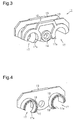
Fig. 3 is a perspective view of a roller holder according to a second embodiment; -
Fig. 4 is a perspective view of the roller holder ofFig. 3 , with parts cut away; -
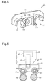
Fig. 5 is a perspective view of a roller holder according to a third embodiment, with parts cut away; -
Fig. 6 is a side view of a detaching top roller in the prior arts, illustrating the supporting structure; -
Fig. 7A is a schematic side view of the detaching top roller ofFig. 6 , illustrating the supporting structure; -
Fig. 7B is a schematic side view ofFig. 6 in the prior arts, illustrating the roller holder placed at a releasing position; and -
Fig. 7C is a schematic side view ofFig. 6 in the prior arts, illustrating a state in which a detaching top roller has fallen off. - A first embodiment of the present invention will now be described with reference to
Figs. 1 to 2C . - As shown
Fig. 1 , aroller holder 11, which is a detaching top roller supporting portion, is symmetrically formed. Aninsert portion 12 is formed in the middle of theroller holder 11. Theinsert portion 12 receives one end of a plunger or a piston (not shown), which constitutes a pressing mechanism. A pair of supportingwalls 13 is arranged to sandwich theinsert portion 12. Each of the supportingwalls 13 includes aninsert hole 14. A fixing screw (not shown), which fixes the plunger or the piston inserted in theinsert portion 12 to theroller holder 11, is inserted into theinsert hole 14. A detaching top roller 15 (hereinafter, referred to as simply a top roller 15) and abearing 16 are indicated by long dashed two short dashed lines inFig. 1 . Theroller holder 11 includes holdingportions 17 on both sides of theinsert hole 14. The holdingportions 17 detachably holdbearings 16. Theinsert portion 12, the supportingwalls 13, and the holdingportions 17 are made of plastic. - As shown in
Figs. 2A and2B , each holdingportion 17 is shaped like an arc. Each bearing 16 is attachable to and detachable from the holdingportion 17 by moving the bearing 16 with thetop roller 15 in a direction perpendicular to the axial direction of the holdingportion 17. The holdingportion 17 is formed such that the inner face (an arc face) of the holdingportion 17 has a central angle of 180° or more, i.e., the inner face (the arc face) of the holdingportion 17 is larger than a half circle. Thebearing 16 is attached to or detached from the holdingportion 17 by moving thebearing 16 in the direction perpendicular to the axial direction of the holdingportion 17 while the space between the circumferential ends of the holdingportion 17 is widened. - As shown in
Fig. 2B , the holdingportions 17 are integrally formed with the two supportingwalls 13. Each holdingportion 17 includes cutouts formed between the ends in the axial direction of the holdingportion 17 and the respective supportingwalls 13, which face the ends. In detail, the entire circumference at either end in the axial direction of the holdingportion 17 is not integrally formed with the supportingwalls 13. As shown inFig. 2B , the holdingportions 17 includearc portions 17a, which are portions that face each other.Spaces 18 are formed between thearc portions 17a and the respective supportingwalls 13. Thearc portions 17a, which extend in parallel with these spaces18, are deformable. Each holdingportion 17 is formed such that the inner surface of the holdingportion 17 that contacts the outer surface of thebearing 16 has a curvature radius substantially the same as that of the outer surface of thebearing 16. In a state in which the holdingportion 17 holds thebearing 16, thecorresponding arc portion 17a, which extends in parallel with the correspondingspaces 18, are pushed and widened radially outward. Thus, thearc portions 17a exert a bias that presses the bearing 16 with its own elastic force. - A
metal spring 19 is attached to the outer circumferential surface of the holdingportion 17. Themetal spring 19 assists the holding force with which the holdingportion 17 holds thebearing 16. Themetal spring 19 is a plate spring made of spring steel. As shown inFig. 2C , themetal spring 19 is curved to form an arc. The circumferential length of themetal spring 19 is longer than the circumferential length of the outer circumferential surface of the holdingportion 17. Themetal spring 19 hashook portions 19a, which are opposed to each other at the circumferential ends. Thehook portions 19a are formed by bending the circumferential ends of themetal spring 19. The inner surface of themetal spring 19 is in contact with the outer circumferential surface of the holdingportion 17. Thehook portions 19a are hooked to the respective ends of the holdingportion 17 to mount themetal spring 19 to the holdingportion 17. Themetal spring 19 is a separate member from the holdingportion 17. - Operation of the above-illustrated
roller holder 11 will now be described. - The
roller holder 11 is used in a state in which theroller holder 11 is fixed to a plunger (not shown), which is inserted in theinsert portion 12. Basically in the similar way to the prior arts (aroller holder 45 shown inFig. 6 ), theroller holder 11 supports thetop roller 15 via thebearing 16 held by the holdingportion 17, and the plunger presses thetop roller 15 against a detaching roller (not shown). At this time, theroller holder 11 is placed at a pressing position at which thetop roller 15 presses a fleece (not shown). - The holding
portion 17 presses and holds the bearing 16 with the elastic force of thecorresponding arc portions 17a, which are pressed and widened radially outward. An operator manually attaches thetop roller 15 to the holdingportion 17 or detaches thetop roller 15 from the holdingportion 17 while theroller holder 11 is separated from the detaching roller, i.e., theroller holder 11 is placed at a released position. - When the holding
portion 17 continuously holds thebearing 16 for a long period of time or temporal change occurs, the elasticity of the plastic of which the holdingportion 17 is made is decreased. As in the prior arts, in a case in which the holdingportion 17 is made of only plastic, when the elasticity of the plastic decrease due to temporal change and the like, the holding force of the holdingportion 17 decreases. Thus, in placing theroller holder 11 at the released position for maintenance work and the like, when vigorous release of the pressing mechanism separates theroller holder 11 from the detaching roller, the top roller may fall off the holdingportion 17. - In the present embodiment, the
metal spring 19 arranged to cover the outer circumference of the plastic-made holdingportion 17 assists the holding force of the holdingportion 17. Even when the elasticity of the plastic-made holdingportion 17 decreases due to temporal change and the like, the elasticity of themetal spring 19 does not decrease. Even after long-term use, the holdingportion 17 stably holds thebearing 16. Thus, in releasing the pressing mechanism for maintenance work and the like, thetop roller 15 is prevented from falling off the holdingportion 17 even if releasing operation is not carefully and slowly performed. - According to the present embodiment, the following advantages are achieved.
- (1) The roller holder 11 (the detaching top roller supporting portion) for the comber supports the
top roller 15 via thebearing 16. Theroller holder 11 includes the holdingportion 17, which detachably holds thebearing 16. Moreover, at least a part of the holdingportion 17 that contacts thebearing 16 is made of synthetic polymer (plastic in the present embodiment). Theroller holder 11 has themetal spring 19, which assists the holding force of the holdingportion 17. Thus, it is possible to detach thetop roller 15 from the holdingportion 17 without using a tool. Even if the holding force of the holdingportion 17, which holds thebearing 16, decreases due to temporal change and the like, the holdingportion 17 can holds thebearing 16 without difficulty. - (2) The
metal spring 19 is a plate spring. Themetal spring 19 is not limited to the plate spring. Themetal spring 19 may be formed by a plurality of C-shaped (an arc shape) wires. However, it is easier to manufacture and attach the plate spring. - (3) The
metal spring 19 is a separate member from the holdingportion 17. Thus, themetal spring 19 can be retrofitted to the detaching top roller supporting portion of an existing comber. - (4) The
metal spring 19 is curved like an arc and has thehook portions 19a at the circumferential ends. Thehook portions 19a are hooked to the circumferential ends of the holdingportion 17 and attached to the holdingportion 17. Thus, themetal spring 19 is easily attached to the holdingportion 17. Change in the attaching position of themetal spring 19, which is caused by the machine vibration, and fall of themetal spring 19 off the holdingportion 17 are prevented after themetal spring 19 is attached. - A second embodiment will now be described with reference to
Figs. 3 and 4 . In the second embodiment, a manner in which themetal spring 19 is attached to the holdingportion 17 according to the first embodiment is modified. The description of components that are the same as the corresponding components of the first embodiment is omitted. - The two
metal springs 19 are integrally formed with theroller holder 11. In detail, the holdingportions 17 are formed by insert molding such that the metal springs 19 are embedded in the holdingportions 17. As shown inFig. 3 , the metal springs 19 are not visible from the outside of theroller holder 11. -
Fig. 4 is a cross-sectional perspective view of theroller holder 11 taken along a plane that contains the two holdingportions 17. As shown inFig. 4 , each of the metal springs 19 is shaped like a simple arc and arranged over the entire circumferential length of the corresponding holdingportion 17 and inside the holdingportion 17. In other words, themetal spring 19 does not have thehook portions 19a, and the entirety of themetal spring 19 is embedded in the holdingportion 17. - In the present embodiment, in the similar manner to the first embodiment, the
top roller 15 can be detached from the holdingportion 17 without using a tool. Even if the holding force of the holding portion17, which holds thebearing 16, decreases due to temporal change and the like, the bearing 16 can be held without difficulty. - The
metal spring 19 is integrally formed with the holdingportion 17. Thus, themetal spring 19 cannot be lost. - The present invention is not limited to the above-illustrated embodiments, but may be embodied in the following forms.
- In the first and second embodiments, the
metal spring 19 is not limited to a plate spring. For example, themetal spring 19 may be formed by aligning C-shaped wires or bonding C-shaped wires to each other with adhesive. - In the first embodiment, the
hook portions 19a are arranged at circumferential ends of a plate spring as themetal spring 19. The arrangement of thehook portions 19a is not limited to this. For example, ahook portion 19a may be arranged only at one of the circumferential ends of the plate spring, or thehook portions 19a may be omitted. - In the first embodiment, the
metal spring 19 does not need to cover the entire circumference of the holdingportion 17. The configuration of themetal spring 19 may be modified as long as the arc-shapedmetal spring 19 has the central angle of 180° or more. In a case in which themetal spring 19 is shaped not to cover the entire circumference of the holdingportion 17, ahook portion 19a is arranged only at one of circumferential ends of themetal spring 19. - Also in the second embodiment, the
metal spring 19 may have the length shorter than the entire circumference of the holdingportion 17 as long as the central angle is 180° or more. - The configuration of the
metal spring 19 may be modified as long as themetal spring 19 functions to assist the holding force of the holdingportion 17. The configuration of themetal spring 19 is not limited to, as in the above illustrated embodiments, the configuration in which the arc-shapedmetal spring 19 is arranged along the outer circumferential surface of the arc-shaped holdingportion 17 and the configuration in which themetal spring 19 is embedded in the holdingportion 17. For example, as in a third embodiment shown inFig. 5 , ametal spring 19 may be bent to be shaped like a channel or U-shape and mounted between the holdingportions 17 in a state in which themetal spring 19 is in contact with the outer circumferential surfaces of thearc portions 17a of the holdingportions 17. In fixing theroller holder 11 to a plunger or a piston, themetal spring 19 includes aclearance 19b so that themetal spring 19 does not interrupt a plunger or a piston. In this case, onemetal spring 19 can assist the holding force in thearc portions 17a of the two holdingportions 17. - In the above-illustrated embodiments, a part of the holding
portion 17 that is in contact with thebearing 16 is not limited to a smooth surface, but may be a rough surface. - In the above-illustrated embodiments, the
arc portions 17a, which havespaces 18 between the holdingportions 17 and the supportingwalls 13, may be arranged in portions other than the portions in which the holdingportions 17 are opposed to each other. - In the above-illustrated embodiments, each of the holding
portions 17 may have twoarc portions 17a, which are opposed to each other, andspaces 18 may be formed between thearc portions 17a and the respective supportingwalls 13. - In the above-illustrated embodiments, each of the holding
portions 17 does not necessarily need to be shaped like an arc. - In the above-illustrated embodiments, the
roller holder 11 may be made of synthetic rubber instead of plastic. - In the above-illustrated embodiments, the entirety of the
roller holder 11 does not necessarily need to be made of synthetic polymer. The embodiments may be modified as long as at least a portion of the holdingportion 17 that contacts thebearing 16 is made of synthetic polymer. For example, the other portion of the holdingportion 17 may be made of metal or ceramics. - In the third embodiment, the
metal spring 19 is shaped like a channel as shown inFig. 5 . The shape of themetal spring 19 is not limited to the channel. Themetal spring 19 may have two curved portions that come into planar contact with twoarc portions 17a. Even in this case, onemetal spring 19 can press thearc portions 17a of the two holdingportions 17. - The material of the
metal spring 19 is not limited to spring steel. Metal that has a desired elasticity other than the spring steel may be used. - The following is a technical idea that can be obtained from the above illustrated embodiments.
- (1) A metal spring, which is attached to a detaching top roller supporting portion for a comber, wherein:
- the detaching top roller supporting portion includes two holding portions, which hold two detaching top rollers via bearings; and
- the metal spring is arranged between the two holding portions and urges the holding portions to assist holding force with which the holding portions hold the bearings.
- Therefore, the present examples and embodiments are to be considered as illustrative and not restrictive and the invention is not to be limited to the details given herein, but may be modified within the scope and equivalence of the appended claims.
- A detaching top roller supporting portion for a comber supports a detaching top roller via a bearing. The detaching top roller supporting portion includes a holding portion, which detachably holds the bearing. At least a part of the holding portion that is in contact with the bearing is made of synthetic polymer. The detaching top roller supporting portion is characterized by a metal spring, which assists holding force with which the holding portion holds the bearing.
Claims (5)
- A detaching top roller supporting portion for a comber that supports a detaching top roller via a bearing, the detaching top roller supporting portion comprising a holding portion, which detachably holds the bearing, wherein at least a part of the holding portion that is in contact with the bearing is made of synthetic polymer,
the detaching top roller supporting portion being characterized by a metal spring, which assists holding force with which the holding portion holds the bearing. - The detaching top roller supporting portion according to claim 1, wherein the metal spring is a plate spring.
- The detaching top roller supporting portion according to claim 1 or 2, wherein the metal spring is a separate member from the holding portion.
- The detaching top roller supporting portion according to claim 1 or 2, the metal spring is integrally formed with the holding portion.
- The detaching top roller supporting portion according to any one of claims 1 to 4, wherein:the holding portion is one of two holding portions;the metal spring is arranged between the holding portions and urges the holding portions to assist the holding force.
Applications Claiming Priority (1)
| Application Number | Priority Date | Filing Date | Title |
|---|---|---|---|
| JP2014250021A JP6156346B2 (en) | 2014-12-10 | 2014-12-10 | Comb detaching top roller support |
Publications (2)
| Publication Number | Publication Date |
|---|---|
| EP3031962A1 true EP3031962A1 (en) | 2016-06-15 |
| EP3031962B1 EP3031962B1 (en) | 2018-10-17 |
Family
ID=54834687
Family Applications (1)
| Application Number | Title | Priority Date | Filing Date |
|---|---|---|---|
| EP15198175.0A Active EP3031962B1 (en) | 2014-12-10 | 2015-12-07 | Detaching top roller supporting portion for comber |
Country Status (3)
| Country | Link |
|---|---|
| EP (1) | EP3031962B1 (en) |
| JP (1) | JP6156346B2 (en) |
| CN (1) | CN105696119B (en) |
Families Citing this family (3)
| Publication number | Priority date | Publication date | Assignee | Title |
|---|---|---|---|---|
| JP3118669B2 (en) | 1992-02-28 | 2000-12-18 | 株式会社バルダン | sewing machine |
| JP3394059B2 (en) | 1993-01-05 | 2003-04-07 | ジューキ株式会社 | Thread cutting device in automatic sewing machine |
| US12617650B2 (en) | 2023-05-30 | 2026-05-05 | Murata Machinery, Ltd. | Yarn path guide mechanism and textile machine |
Citations (7)
| Publication number | Priority date | Publication date | Assignee | Title |
|---|---|---|---|---|
| US1534784A (en) * | 1924-02-12 | 1925-04-21 | John Hetherington & Sons Ltd | Machine for combing cotton, wool, and the like |
| GB500594A (en) * | 1936-09-05 | 1939-02-13 | Spindel Und Spinnfluegelfabrik | Improvements in or relating to pressure rollers for spinning machines |
| GB607400A (en) * | 1946-02-01 | 1948-08-30 | Hoyt Metal Company Of Great Br | Improvements in bearings |
| GB724483A (en) * | 1953-05-12 | 1955-02-23 | Textile Engineering Corp | Improvements in and relating to top rolls for spinning and roving frames |
| JPH05214615A (en) | 1991-09-05 | 1993-08-24 | Mas Fab Rieter Ag | Detaching roller assembly for combing machine |
| US5283621A (en) * | 1990-08-31 | 1994-02-01 | Kabushiki Kaisha Toshiba | Fixing apparatus and method of supporting a roller shaft of the fixing apparatus |
| EP2671979A2 (en) * | 2012-06-07 | 2013-12-11 | Kabushiki Kaisha Toyota Jidoshokki | Combing machine |
Family Cites Families (7)
| Publication number | Priority date | Publication date | Assignee | Title |
|---|---|---|---|---|
| JPS53165053U (en) * | 1977-06-02 | 1978-12-23 | ||
| DE19641160B4 (en) * | 1996-10-07 | 2007-01-04 | Maschinenfabrik Rieter Ag | Loading system for the top rollers of the pull-off and pull-off roller pairs on combing machines |
| CN1185378C (en) * | 2002-01-10 | 2005-01-19 | 山西经纬合力机械制造公司总厂 | Comber |
| DE202005008570U1 (en) * | 2005-06-01 | 2005-09-08 | Trw Automotive Electronics & Components Gmbh & Co. Kg | Cable e.g. hydraulic cable, fastening device for vehicle, has plastic film partially surrounding reinforcing part upto fastening section, gap for insertion of cable, and peripheral wall with flexible projections stretching inward |
| CN1912204A (en) * | 2005-08-09 | 2007-02-14 | 东台纺织机械有限责任公司 | Cotton-network guide device of combing machine |
| CN201236239Y (en) * | 2008-07-25 | 2009-05-13 | 常州市同和纺织机械制造有限公司 | Connecting mechanism of lever pneumatic swing frame matched compact spinning apparatus |
| CN202327371U (en) * | 2011-11-17 | 2012-07-11 | 北汽福田汽车股份有限公司 | Wire harness passing-hole fixing device |
-
2014
- 2014-12-10 JP JP2014250021A patent/JP6156346B2/en active Active
-
2015
- 2015-12-07 EP EP15198175.0A patent/EP3031962B1/en active Active
- 2015-12-08 CN CN201510893150.4A patent/CN105696119B/en active Active
Patent Citations (8)
| Publication number | Priority date | Publication date | Assignee | Title |
|---|---|---|---|---|
| US1534784A (en) * | 1924-02-12 | 1925-04-21 | John Hetherington & Sons Ltd | Machine for combing cotton, wool, and the like |
| GB500594A (en) * | 1936-09-05 | 1939-02-13 | Spindel Und Spinnfluegelfabrik | Improvements in or relating to pressure rollers for spinning machines |
| GB607400A (en) * | 1946-02-01 | 1948-08-30 | Hoyt Metal Company Of Great Br | Improvements in bearings |
| GB724483A (en) * | 1953-05-12 | 1955-02-23 | Textile Engineering Corp | Improvements in and relating to top rolls for spinning and roving frames |
| US5283621A (en) * | 1990-08-31 | 1994-02-01 | Kabushiki Kaisha Toshiba | Fixing apparatus and method of supporting a roller shaft of the fixing apparatus |
| JPH05214615A (en) | 1991-09-05 | 1993-08-24 | Mas Fab Rieter Ag | Detaching roller assembly for combing machine |
| US5271126A (en) * | 1991-09-05 | 1993-12-21 | Rieter Machine Works, Ltd. | Detaching roller aggregate for a combing machine |
| EP2671979A2 (en) * | 2012-06-07 | 2013-12-11 | Kabushiki Kaisha Toyota Jidoshokki | Combing machine |
Also Published As
| Publication number | Publication date |
|---|---|
| EP3031962B1 (en) | 2018-10-17 |
| CN105696119A (en) | 2016-06-22 |
| CN105696119B (en) | 2018-09-18 |
| JP6156346B2 (en) | 2017-07-05 |
| JP2016108711A (en) | 2016-06-20 |
Similar Documents
| Publication | Publication Date | Title |
|---|---|---|
| EP3031962B1 (en) | Detaching top roller supporting portion for comber | |
| EP3584019B1 (en) | Stripping device for press mold | |
| EP2520697B1 (en) | Device for stopping a rove supply in a spinning apparatus | |
| KR20170020534A (en) | Pressing device for pressing a finishing belt against a workpiece surface | |
| KR101957058B1 (en) | Tool grippers for machine tools | |
| CN106012128B (en) | A compression unit for a drafting mechanism of a spinning machine | |
| JP6016901B2 (en) | Guide element in nipper unit of combing machine | |
| CN106133219B (en) | Top comb for combing machine | |
| EP2174919A3 (en) | Brittle material pliers | |
| US12268625B2 (en) | Pincer nail correction tool | |
| JP6169179B2 (en) | Top comb mounting member | |
| US20090265892A1 (en) | Fixing Device For Fixing Toothed Elements To A Component Of A Textile Machine | |
| CN107109713B (en) | Cage assembly with guide elements | |
| CN110382386A (en) | Thread guides | |
| CN109957901B (en) | Sectional roller | |
| GB2502419A (en) | Card flat for a carding machine, comprising a carrying member and drive transfer element with releasable fastening means | |
| CN109023611A (en) | Free end type spinning machine | |
| CN104105555A (en) | Die holder for press brake | |
| KR102106284B1 (en) | Bolster cushion pin guide for press | |
| JP2019201795A (en) | Ingrown nail corrector and retainer | |
| CN217231056U (en) | Yarn is wire instrument for two-for-one twisting | |
| KR200483628Y1 (en) | A wig clip | |
| KR101962264B1 (en) | Vertical full rotation hook | |
| CN114434127B (en) | Assembly equipment and medical device production line | |
| CN111979618B (en) | Compressor unit for a drafting device of a textile machine |
Legal Events
| Date | Code | Title | Description |
|---|---|---|---|
| PUAI | Public reference made under article 153(3) epc to a published international application that has entered the european phase |
Free format text: ORIGINAL CODE: 0009012 |
|
| 17P | Request for examination filed |
Effective date: 20151207 |
|
| AK | Designated contracting states |
Kind code of ref document: A1 Designated state(s): AL AT BE BG CH CY CZ DE DK EE ES FI FR GB GR HR HU IE IS IT LI LT LU LV MC MK MT NL NO PL PT RO RS SE SI SK SM TR |
|
| AX | Request for extension of the european patent |
Extension state: BA ME |
|
| 17Q | First examination report despatched |
Effective date: 20170728 |
|
| GRAP | Despatch of communication of intention to grant a patent |
Free format text: ORIGINAL CODE: EPIDOSNIGR1 |
|
| INTG | Intention to grant announced |
Effective date: 20180507 |
|
| GRAS | Grant fee paid |
Free format text: ORIGINAL CODE: EPIDOSNIGR3 |
|
| GRAA | (expected) grant |
Free format text: ORIGINAL CODE: 0009210 |
|
| AK | Designated contracting states |
Kind code of ref document: B1 Designated state(s): AL AT BE BG CH CY CZ DE DK EE ES FI FR GB GR HR HU IE IS IT LI LT LU LV MC MK MT NL NO PL PT RO RS SE SI SK SM TR |
|
| REG | Reference to a national code |
Ref country code: GB Ref legal event code: FG4D |
|
| REG | Reference to a national code |
Ref country code: CH Ref legal event code: EP Ref country code: CH Ref legal event code: NV Representative=s name: NOVAGRAAF INTERNATIONAL SA, CH |
|
| REG | Reference to a national code |
Ref country code: IE Ref legal event code: FG4D |
|
| REG | Reference to a national code |
Ref country code: DE Ref legal event code: R096 Ref document number: 602015018222 Country of ref document: DE Ref country code: AT Ref legal event code: REF Ref document number: 1054161 Country of ref document: AT Kind code of ref document: T Effective date: 20181115 |
|
| REG | Reference to a national code |
Ref country code: NL Ref legal event code: MP Effective date: 20181017 |
|
| REG | Reference to a national code |
Ref country code: LT Ref legal event code: MG4D |
|
| REG | Reference to a national code |
Ref country code: AT Ref legal event code: MK05 Ref document number: 1054161 Country of ref document: AT Kind code of ref document: T Effective date: 20181017 |
|
| PG25 | Lapsed in a contracting state [announced via postgrant information from national office to epo] |
Ref country code: NL Free format text: LAPSE BECAUSE OF FAILURE TO SUBMIT A TRANSLATION OF THE DESCRIPTION OR TO PAY THE FEE WITHIN THE PRESCRIBED TIME-LIMIT Effective date: 20181017 |
|
| PG25 | Lapsed in a contracting state [announced via postgrant information from national office to epo] |
Ref country code: IS Free format text: LAPSE BECAUSE OF FAILURE TO SUBMIT A TRANSLATION OF THE DESCRIPTION OR TO PAY THE FEE WITHIN THE PRESCRIBED TIME-LIMIT Effective date: 20190217 Ref country code: NO Free format text: LAPSE BECAUSE OF FAILURE TO SUBMIT A TRANSLATION OF THE DESCRIPTION OR TO PAY THE FEE WITHIN THE PRESCRIBED TIME-LIMIT Effective date: 20190117 Ref country code: PL Free format text: LAPSE BECAUSE OF FAILURE TO SUBMIT A TRANSLATION OF THE DESCRIPTION OR TO PAY THE FEE WITHIN THE PRESCRIBED TIME-LIMIT Effective date: 20181017 Ref country code: BG Free format text: LAPSE BECAUSE OF FAILURE TO SUBMIT A TRANSLATION OF THE DESCRIPTION OR TO PAY THE FEE WITHIN THE PRESCRIBED TIME-LIMIT Effective date: 20190117 Ref country code: ES Free format text: LAPSE BECAUSE OF FAILURE TO SUBMIT A TRANSLATION OF THE DESCRIPTION OR TO PAY THE FEE WITHIN THE PRESCRIBED TIME-LIMIT Effective date: 20181017 Ref country code: LT Free format text: LAPSE BECAUSE OF FAILURE TO SUBMIT A TRANSLATION OF THE DESCRIPTION OR TO PAY THE FEE WITHIN THE PRESCRIBED TIME-LIMIT Effective date: 20181017 Ref country code: LV Free format text: LAPSE BECAUSE OF FAILURE TO SUBMIT A TRANSLATION OF THE DESCRIPTION OR TO PAY THE FEE WITHIN THE PRESCRIBED TIME-LIMIT Effective date: 20181017 Ref country code: HR Free format text: LAPSE BECAUSE OF FAILURE TO SUBMIT A TRANSLATION OF THE DESCRIPTION OR TO PAY THE FEE WITHIN THE PRESCRIBED TIME-LIMIT Effective date: 20181017 Ref country code: AT Free format text: LAPSE BECAUSE OF FAILURE TO SUBMIT A TRANSLATION OF THE DESCRIPTION OR TO PAY THE FEE WITHIN THE PRESCRIBED TIME-LIMIT Effective date: 20181017 Ref country code: FI Free format text: LAPSE BECAUSE OF FAILURE TO SUBMIT A TRANSLATION OF THE DESCRIPTION OR TO PAY THE FEE WITHIN THE PRESCRIBED TIME-LIMIT Effective date: 20181017 |
|
| PG25 | Lapsed in a contracting state [announced via postgrant information from national office to epo] |
Ref country code: PT Free format text: LAPSE BECAUSE OF FAILURE TO SUBMIT A TRANSLATION OF THE DESCRIPTION OR TO PAY THE FEE WITHIN THE PRESCRIBED TIME-LIMIT Effective date: 20190217 Ref country code: SE Free format text: LAPSE BECAUSE OF FAILURE TO SUBMIT A TRANSLATION OF THE DESCRIPTION OR TO PAY THE FEE WITHIN THE PRESCRIBED TIME-LIMIT Effective date: 20181017 Ref country code: AL Free format text: LAPSE BECAUSE OF FAILURE TO SUBMIT A TRANSLATION OF THE DESCRIPTION OR TO PAY THE FEE WITHIN THE PRESCRIBED TIME-LIMIT Effective date: 20181017 Ref country code: RS Free format text: LAPSE BECAUSE OF FAILURE TO SUBMIT A TRANSLATION OF THE DESCRIPTION OR TO PAY THE FEE WITHIN THE PRESCRIBED TIME-LIMIT Effective date: 20181017 Ref country code: GR Free format text: LAPSE BECAUSE OF FAILURE TO SUBMIT A TRANSLATION OF THE DESCRIPTION OR TO PAY THE FEE WITHIN THE PRESCRIBED TIME-LIMIT Effective date: 20190118 |
|
| REG | Reference to a national code |
Ref country code: DE Ref legal event code: R097 Ref document number: 602015018222 Country of ref document: DE |
|
| PG25 | Lapsed in a contracting state [announced via postgrant information from national office to epo] |
Ref country code: DK Free format text: LAPSE BECAUSE OF FAILURE TO SUBMIT A TRANSLATION OF THE DESCRIPTION OR TO PAY THE FEE WITHIN THE PRESCRIBED TIME-LIMIT Effective date: 20181017 Ref country code: CZ Free format text: LAPSE BECAUSE OF FAILURE TO SUBMIT A TRANSLATION OF THE DESCRIPTION OR TO PAY THE FEE WITHIN THE PRESCRIBED TIME-LIMIT Effective date: 20181017 |
|
| PLBE | No opposition filed within time limit |
Free format text: ORIGINAL CODE: 0009261 |
|
| STAA | Information on the status of an ep patent application or granted ep patent |
Free format text: STATUS: NO OPPOSITION FILED WITHIN TIME LIMIT |
|
| PG25 | Lapsed in a contracting state [announced via postgrant information from national office to epo] |
Ref country code: LU Free format text: LAPSE BECAUSE OF NON-PAYMENT OF DUE FEES Effective date: 20181207 Ref country code: EE Free format text: LAPSE BECAUSE OF FAILURE TO SUBMIT A TRANSLATION OF THE DESCRIPTION OR TO PAY THE FEE WITHIN THE PRESCRIBED TIME-LIMIT Effective date: 20181017 Ref country code: RO Free format text: LAPSE BECAUSE OF FAILURE TO SUBMIT A TRANSLATION OF THE DESCRIPTION OR TO PAY THE FEE WITHIN THE PRESCRIBED TIME-LIMIT Effective date: 20181017 Ref country code: SK Free format text: LAPSE BECAUSE OF FAILURE TO SUBMIT A TRANSLATION OF THE DESCRIPTION OR TO PAY THE FEE WITHIN THE PRESCRIBED TIME-LIMIT Effective date: 20181017 Ref country code: MC Free format text: LAPSE BECAUSE OF FAILURE TO SUBMIT A TRANSLATION OF THE DESCRIPTION OR TO PAY THE FEE WITHIN THE PRESCRIBED TIME-LIMIT Effective date: 20181017 Ref country code: SM Free format text: LAPSE BECAUSE OF FAILURE TO SUBMIT A TRANSLATION OF THE DESCRIPTION OR TO PAY THE FEE WITHIN THE PRESCRIBED TIME-LIMIT Effective date: 20181017 |
|
| REG | Reference to a national code |
Ref country code: IE Ref legal event code: MM4A |
|
| 26N | No opposition filed |
Effective date: 20190718 |
|
| REG | Reference to a national code |
Ref country code: BE Ref legal event code: MM Effective date: 20181231 |
|
| PG25 | Lapsed in a contracting state [announced via postgrant information from national office to epo] |
Ref country code: IE Free format text: LAPSE BECAUSE OF NON-PAYMENT OF DUE FEES Effective date: 20181207 Ref country code: FR Free format text: LAPSE BECAUSE OF NON-PAYMENT OF DUE FEES Effective date: 20181217 Ref country code: SI Free format text: LAPSE BECAUSE OF FAILURE TO SUBMIT A TRANSLATION OF THE DESCRIPTION OR TO PAY THE FEE WITHIN THE PRESCRIBED TIME-LIMIT Effective date: 20181017 |
|
| PG25 | Lapsed in a contracting state [announced via postgrant information from national office to epo] |
Ref country code: BE Free format text: LAPSE BECAUSE OF NON-PAYMENT OF DUE FEES Effective date: 20181231 |
|
| PG25 | Lapsed in a contracting state [announced via postgrant information from national office to epo] |
Ref country code: MT Free format text: LAPSE BECAUSE OF NON-PAYMENT OF DUE FEES Effective date: 20181207 |
|
| PG25 | Lapsed in a contracting state [announced via postgrant information from national office to epo] |
Ref country code: TR Free format text: LAPSE BECAUSE OF FAILURE TO SUBMIT A TRANSLATION OF THE DESCRIPTION OR TO PAY THE FEE WITHIN THE PRESCRIBED TIME-LIMIT Effective date: 20181017 |
|
| PG25 | Lapsed in a contracting state [announced via postgrant information from national office to epo] |
Ref country code: HU Free format text: LAPSE BECAUSE OF FAILURE TO SUBMIT A TRANSLATION OF THE DESCRIPTION OR TO PAY THE FEE WITHIN THE PRESCRIBED TIME-LIMIT; INVALID AB INITIO Effective date: 20151207 Ref country code: CY Free format text: LAPSE BECAUSE OF FAILURE TO SUBMIT A TRANSLATION OF THE DESCRIPTION OR TO PAY THE FEE WITHIN THE PRESCRIBED TIME-LIMIT Effective date: 20181017 Ref country code: MK Free format text: LAPSE BECAUSE OF NON-PAYMENT OF DUE FEES Effective date: 20181017 |
|
| GBPC | Gb: european patent ceased through non-payment of renewal fee |
Effective date: 20191207 |
|
| PG25 | Lapsed in a contracting state [announced via postgrant information from national office to epo] |
Ref country code: GB Free format text: LAPSE BECAUSE OF NON-PAYMENT OF DUE FEES Effective date: 20191207 |
|
| P01 | Opt-out of the competence of the unified patent court (upc) registered |
Effective date: 20230519 |
|
| REG | Reference to a national code |
Ref country code: CH Ref legal event code: U11 Free format text: ST27 STATUS EVENT CODE: U-0-0-U10-U11 (AS PROVIDED BY THE NATIONAL OFFICE) Effective date: 20260101 |
|
| PGFP | Annual fee paid to national office [announced via postgrant information from national office to epo] |
Ref country code: DE Payment date: 20251028 Year of fee payment: 11 |
|
| PGFP | Annual fee paid to national office [announced via postgrant information from national office to epo] |
Ref country code: IT Payment date: 20251121 Year of fee payment: 11 |
|
| PGFP | Annual fee paid to national office [announced via postgrant information from national office to epo] |
Ref country code: CH Payment date: 20260101 Year of fee payment: 11 |