EP3031767A1 - Elevator door sill - Google Patents
Elevator door sill Download PDFInfo
- Publication number
- EP3031767A1 EP3031767A1 EP14197804.9A EP14197804A EP3031767A1 EP 3031767 A1 EP3031767 A1 EP 3031767A1 EP 14197804 A EP14197804 A EP 14197804A EP 3031767 A1 EP3031767 A1 EP 3031767A1
- Authority
- EP
- European Patent Office
- Prior art keywords
- elevator
- trash
- air channel
- groove
- door
- Prior art date
- Legal status (The legal status is an assumption and is not a legal conclusion. Google has not performed a legal analysis and makes no representation as to the accuracy of the status listed.)
- Granted
Links
Images


Classifications
-
- B—PERFORMING OPERATIONS; TRANSPORTING
- B66—HOISTING; LIFTING; HAULING
- B66B—ELEVATORS; ESCALATORS OR MOVING WALKWAYS
- B66B13/00—Doors, gates, or other apparatus controlling access to, or exit from, cages or lift well landings
- B66B13/30—Constructional features of doors or gates
- B66B13/301—Details of door sills
-
- B—PERFORMING OPERATIONS; TRANSPORTING
- B66—HOISTING; LIFTING; HAULING
- B66B—ELEVATORS; ESCALATORS OR MOVING WALKWAYS
- B66B13/00—Doors, gates, or other apparatus controlling access to, or exit from, cages or lift well landings
- B66B13/24—Safety devices in passenger lifts, not otherwise provided for, for preventing trapping of passengers
- B66B13/28—Safety devices in passenger lifts, not otherwise provided for, for preventing trapping of passengers between car or cage and wells
- B66B13/285—Toe guards or apron devices
Definitions
- the present invention relates to an elevator having at least one elevator car driving in an elevator shaft driven by an elevator drive.
- the elevator car has at least one car door and a door sill at the bottom of the car door on the same level as the floor of the elevator car.
- the door sill comprises at least one groove, in which the car door is guided whereby in the groove at least one trash hole is located to prevent trash from accumulating in the groove.
- these trash holes generate not unessential noise which could increase the noise volume in the elevator car possibly to values about 3dB.
- the trash hole is connected with a toe guard which extends downwards at the landing side edge of the door sill.
- the trash hole is connected with a first upper end of an air channel extending downwards from the door sill and comprises at least one channel portion extending with a direction component in horizontal direction, which air channel is connected with the toe guard.
- the feature that the air channel extends in a direction having a horizontal direction component comprises at least channel portions which extend in horizontal direction or which are tilted with respect to a straight vertical direction by at least 10 degrees, particularly by at least 20 degrees, preferably up to 45 degrees.
- the channel may also extend vertically but may include inner portions which are separated so as to extend in a horizontal direction or with a horizontal direction component.
- the extension of the air channel with a horizontal direction component ensures that the channel is not directed exactly vertically.
- the lower opening of the air channel may be directed sideward, so that the air cannot directly enter the air channel when the elevator car is traveling downwards.
- the blowing of air directly through the air channel with high velocity during the travel of the car is prevented, which reduces noise.
- This air channel having at least also a horizontal extension component acts as a kind of obstacle and therefore prevents wind from blowing from directly upwards or downwards through the trash holes when the car moves upwards or downwards with nominal velocity.
- the horizontal direction component it is ensured that the wind is at least diverted which reduces the wind speed through the air channel and thus reduces generated noise.
- the air channel preferably forms an acoustic labyrinth.
- This acoustic labyrinth not only reduces the velocity of the wind blowing through the air channel and the trash hole but also reduces noise which is generated by said wind.
- the air channel may also reduce noise which comes from the elevator shaft.
- the door sill comprises at least one trash hole, preferably two trash holes, only in its central portion (if the car door is a centrally closing door).
- trash accumulating in the groove is pushed by the guide of the elevator door towards the trash hole. Therefore, the location of the trash hole is advantageous in the region of the end position of the door guide when the door is closed.
- two trash holes in the central part of the door sill are preferable.
- trash holes are provided in the central portion, these trash holes are connected with corresponding air channels, whereby the two air channels extend in a mutual angle of 25 to 90 degrees.
- the air channel has a horizontal component which tends to reduce the airflow in the channel, and on the other hand, the fact that the two air channels are directed away from each other leads to a better stiffening of the toe guard via the air channels over the complete width of the toe guard.
- both trash holes could be connected to a common air channel which is tilted towards the vertical direction and/or has horizontally extending portions.
- the air channel has an outlet opening at its second lower end which outlet opening is directed in horizontal direction, i.e. the normal vector of the opening extends in horizontal direction.
- the orientation of the lower outlet openings of the air channel in horizontal direction has the advantage that the wind cannot blow directly from below into the air channels when the elevator car moves downwards but the wind has to take a path from aside into the air channel. Thus, this measure essentially reduces wind entering the air channel and reduces airflow speed within the air channel.
- the air channel could also have a downwards (vertical) opening which is horizontally offset with respect to the corresponding trash-hole(s) in the door sill, which also leads to a reduced air velocity in the air channel.
- the air channel forms a bracing element stiffening the toe guard.
- the air channels can be provided as a U-profile metal sheet which is fixed to the toe guard plate which is also preferably a metal plate. This fixing can be done with screwing or with welding or other connection techniques.
- the toe guard is on its inner side stiffened by these U-profiles leads to an essential stiffening of the toe guard plate via the air channels.
- the air channels act as a bracing element which reduces vibrations of the toe guard during the ride in the elevator shaft and therefore furthermore reduce the noise level in the shaft and thus the noise level in the elevator car improving riding comfort of the elevator car.
- the air channel as well as the toe guard are formed of sheet metal which is easy to manufacture.
- the connection between the air channel and the toe guard can be realised technically simple, e.g. via welding points.
- the toe guard extends from the door sill in vertical direction downwards as it is most preferable for the protection of passengers.
- the groove does not have any trash holes outside of a central portion of preferably 30 cm, particularly 20 cm of the door sill.
- the noise level can be reduced.
- These outer trash holes have revealed to be only of minor importance regarding the discharge of waste in the grooves. Therefore, on that behalf, the location of the trash holes only in the central portion has been revealed sufficient for waste discharge and advantageous with respect to noise reduction.
- the car door is guided by door rollers or pins running in the groove of the door sill.
- This arrangement has been established as a functional and a reliable element in a per se known manner.
- the second lower end of the air channel does not have any opening extending downwards. Via this measure, it is avoided that wind enters the air channel directly from below when the elevator car is travelling downwards. Thus, air speed in the air channel is reduced to a minimum and the resulting generated noise is reduced.
- the invention also refers to an elevator group having several elevators according to the above-mentioned specifications.
- Fig. 1 shows the floor 10 of an elevator car which is at the car door side terminated by a door sill 12 having two parallel grooves 14, 16 for guiding the car doors between their open and closed position.
- the two grooves 14, 16 have two trash holes 20a, 20b, 22a, 22b respectively, which are on their bottom side connected with a horizontally extending first portion 23a, 23b of an air channel 24a, 24b.
- the first portion 23a,b has a sloped bottom to assist the trash entering through the trash-hole(s) to advance to a vertically extending second portion 25a, 25b which is also tilted with respect to the vertical by about 15 degrees (See Fig. 2 ).
- the air channels 24a, 24b are embodied as a U-profile made of a metal sheet, which profile has flat extensions 26 which with the second air channel portion 25a, 25b is welded to a toe guard 28.
- the toe guard 28 has a first upper portion 29 extending from the front edge of the door sill 12 vertically downwards and a second lower portion 30 which is directed vertically downwards but slightly tilted in-wards to the car.
- the air channel 24 has at its lower end 34 an outlet opening 32 which is open to the side, i.e.
- Both air channels 24a, 24b are extending in a mutual angle of about 30 degrees, i.e. 15 degrees with respect to the vertical direction which leads to a better noise reduction and to a better distribution of the bracing effect of the air channels 24a, 24b along the toe guard 28.
- the air channel forms an acoustic labyrinth and reduces noise created by the trash holes 20a,b and 22a,b essentially.
- the door sill 12 comprises two grooves 12, 14.
- the door sill may also comprise only one groove or three or four grooves according to the number of door leaves to be guided.
- the shown door sill is a door sill for a centrally opening car door. If the door opens to one side, the trash holes are of course located at that side where the door closes.
- trash holes instead of two trash holes per groove, also one or three trash holes may be provided.
- the geometry of the trash holes is shown as elliptic.
- the trash holes can of course have a rectangular or circular form as desired.
- the toe guard 28 consists of a vertical first upper part 29 and an inwardly bent lower part 30.
- the toe guard can be embodied as one single plate which is extending vertically or which is smoothly curved inwardly.
- the toe guard as well as the air channels need not to be manufactured from sheet metal but may also consist of other materials, e.g. plastics.
Landscapes
- Elevator Door Apparatuses (AREA)
- Cage And Drive Apparatuses For Elevators (AREA)
Abstract
Description
- The present invention relates to an elevator having at least one elevator car driving in an elevator shaft driven by an elevator drive. The elevator car has at least one car door and a door sill at the bottom of the car door on the same level as the floor of the elevator car. The door sill comprises at least one groove, in which the car door is guided whereby in the groove at least one trash hole is located to prevent trash from accumulating in the groove. Particularly in fast running elevators, these trash holes generate not unessential noise which could increase the noise volume in the elevator car possibly to values about 3dB.
- It is therefore object of the invention to provide an elevator, particularly fast running elevator, having a reduced noise generation.
- The object of the invention is solved with an elevator according to claim 1. Advantageous embodiments of the invention are subject-matter of the dependent claims. Inventive embodiments are also presented in the description and in the drawings of the present application. The inventive content may also consist of several separate inventions, especially if the invention is considered in the light of explicit or implicit subtasks or with respect to advantages or sets of advantages achieved. In this case, some of the attributes contained in the claims below may be superfluous from the point of view of separate inventive concepts.
- According to the invention, the trash hole is connected with a toe guard which extends downwards at the landing side edge of the door sill. According to the invention, the trash hole is connected with a first upper end of an air channel extending downwards from the door sill and comprises at least one channel portion extending with a direction component in horizontal direction, which air channel is connected with the toe guard. The feature that the air channel extends in a direction having a horizontal direction component comprises at least channel portions which extend in horizontal direction or which are tilted with respect to a straight vertical direction by at least 10 degrees, particularly by at least 20 degrees, preferably up to 45 degrees. Of course, the channel may also extend vertically but may include inner portions which are separated so as to extend in a horizontal direction or with a horizontal direction component. The extension of the air channel with a horizontal direction component ensures that the channel is not directed exactly vertically. Alternatively or additionally to the air channel portion extending with a horizontal component the lower opening of the air channel may be directed sideward, so that the air cannot directly enter the air channel when the elevator car is traveling downwards. Thus the blowing of air directly through the air channel with high velocity during the travel of the car is prevented, which reduces noise.
- This air channel having at least also a horizontal extension component acts as a kind of obstacle and therefore prevents wind from blowing from directly upwards or downwards through the trash holes when the car moves upwards or downwards with nominal velocity. By the horizontal direction component it is ensured that the wind is at least diverted which reduces the wind speed through the air channel and thus reduces generated noise.
- Therefore, the air channel preferably forms an acoustic labyrinth. This acoustic labyrinth not only reduces the velocity of the wind blowing through the air channel and the trash hole but also reduces noise which is generated by said wind. The air channel may also reduce noise which comes from the elevator shaft.
- Preferably, the door sill comprises at least one trash hole, preferably two trash holes, only in its central portion (if the car door is a centrally closing door). Usually, trash accumulating in the groove is pushed by the guide of the elevator door towards the trash hole. Therefore, the location of the trash hole is advantageous in the region of the end position of the door guide when the door is closed. As usually there is a centrally closing car door with two door leaves, two trash holes in the central part of the door sill are preferable.
- Therefore, if two trash holes are provided in the central portion, these trash holes are connected with corresponding air channels, whereby the two air channels extend in a mutual angle of 25 to 90 degrees. By this measure, the air channel has a horizontal component which tends to reduce the airflow in the channel, and on the other hand, the fact that the two air channels are directed away from each other leads to a better stiffening of the toe guard via the air channels over the complete width of the toe guard. Of course also both trash holes could be connected to a common air channel which is tilted towards the vertical direction and/or has horizontally extending portions.
- In a preferred embodiment of the invention, the air channel has an outlet opening at its second lower end which outlet opening is directed in horizontal direction, i.e. the normal vector of the opening extends in horizontal direction. This means that the edges of the opening are preferably in a vertical plane. The orientation of the lower outlet openings of the air channel in horizontal direction has the advantage that the wind cannot blow directly from below into the air channels when the elevator car moves downwards but the wind has to take a path from aside into the air channel. Thus, this measure essentially reduces wind entering the air channel and reduces airflow speed within the air channel.
- Of course, the air channel could also have a downwards (vertical) opening which is horizontally offset with respect to the corresponding trash-hole(s) in the door sill, which also leads to a reduced air velocity in the air channel.
- In a preferred embodiment of the invention, the air channel forms a bracing element stiffening the toe guard. For example, the air channels can be provided as a U-profile metal sheet which is fixed to the toe guard plate which is also preferably a metal plate. This fixing can be done with screwing or with welding or other connection techniques. By the fact that the toe guard is on its inner side stiffened by these U-profiles leads to an essential stiffening of the toe guard plate via the air channels. Accordingly, the air channels act as a bracing element which reduces vibrations of the toe guard during the ride in the elevator shaft and therefore furthermore reduce the noise level in the shaft and thus the noise level in the elevator car improving riding comfort of the elevator car.
- In a preferred embodiment of the invention, the air channel as well as the toe guard are formed of sheet metal which is easy to manufacture. In this case also the connection between the air channel and the toe guard can be realised technically simple, e.g. via welding points. Generally, as it is per se known the toe guard extends from the door sill in vertical direction downwards as it is most preferable for the protection of passengers.
- Preferably, the groove does not have any trash holes outside of a central portion of preferably 30 cm, particularly 20 cm of the door sill. By omitting the currently used trash holes at the outer end portions of the grooves, the noise level can be reduced. These outer trash holes have revealed to be only of minor importance regarding the discharge of waste in the grooves. Therefore, on that behalf, the location of the trash holes only in the central portion has been revealed sufficient for waste discharge and advantageous with respect to noise reduction.
- Preferably, the car door is guided by door rollers or pins running in the groove of the door sill. This arrangement has been established as a functional and a reliable element in a per se known manner.
- In a preferred embodiment of the invention, the second lower end of the air channel does not have any opening extending downwards. Via this measure, it is avoided that wind enters the air channel directly from below when the elevator car is travelling downwards. Thus, air speed in the air channel is reduced to a minimum and the resulting generated noise is reduced.
- The invention also refers to an elevator group having several elevators according to the above-mentioned specifications.
- It shall be clear for the skilled person that the above-mentioned embodiments can be combined with each other as long as it is technically feasible.
- The invention is now described in the drawings by means of an example, wherein
-
Fig. 1 shows a vertical section of a part of an elevator car in the region of the door sill and toe guard, -
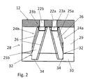
Fig. 2 shows a vertical section II-II fromFig. 1 , and -
Fig. 3 shows a top view III fromFig. 1 . -
Fig. 1 shows thefloor 10 of an elevator car which is at the car door side terminated by adoor sill 12 having twoparallel grooves grooves trash holes first portion air channel first portion 23a,b has a sloped bottom to assist the trash entering through the trash-hole(s) to advance to a vertically extendingsecond portion Fig. 2 ). Theair channels flat extensions 26 which with the secondair channel portion toe guard 28. Thetoe guard 28 has a firstupper portion 29 extending from the front edge of thedoor sill 12 vertically downwards and a secondlower portion 30 which is directed vertically downwards but slightly tilted in-wards to the car. The air channel 24 has at itslower end 34 an outlet opening 32 which is open to the side, i.e. extending horizontally (their normal vector pointing horizontally, which means the edges of the opening lying in a vertical plane), so that air cannot enter the air channel directly from below as thelower end 34 of theair channels bent portion 30 of thetoe guard plate 28. - Both
air channels air channels toe guard 28. - By the first upper
horizontal portions lower portions outlet openings 32 of theair channels trash holes 20a,b and 22a,b essentially. - It is clear, that the above-mentioned embodiment can be varied according to design necessities. For example, the
door sill 12 comprises twogrooves - Instead of two trash holes per groove, also one or three trash holes may be provided. The geometry of the trash holes is shown as elliptic. The trash holes can of course have a rectangular or circular form as desired.
- The
toe guard 28 consists of a vertical firstupper part 29 and an inwardly bentlower part 30. Of course, the toe guard can be embodied as one single plate which is extending vertically or which is smoothly curved inwardly. - The toe guard as well as the air channels need not to be manufactured from sheet metal but may also consist of other materials, e.g. plastics.
Claims (15)
- Elevator comprising at least one elevator car driving in an elevator shaft driven by an elevator drive, which elevator car has at least one car door and a door sill (12) at the bottom of the car door, which door sill comprises at least one groove (14, 16), in which the car door is guided, in which groove at least one trash hole (20a, 20b, 22a, 22b) is located to prevent trash from accumulating in the groove, whereby the elevator car further comprises a toe guard (28) which extends with a direction component in length direction of the shaft, characterized that the trash hole (20a, 20b, 22a, 22b) is connected with a first upper end (23a, 23b) of an air channel (24a, 24b) extending downwards from the door sill and comprises at least one channel portion (23a, 23b, 25a, 25b) extending with a direction component in horizontal direction and/or having an opening directed sideward, which air channel (24a, 24b) is connected with the toe guard (28).
- Elevator according to claim 1, wherein the air channel (24a, 24b) forms an acoustic labyrinth.
- Elevator according to claim 1 or 2, wherein the groove (14, 16) of the door sill (12) comprises at least one trash hole (20a, 20b, 22a, 22b) only in its central portion.
- Elevator according to claim 3, wherein the toe guard (28) comprises at least one plate-like member (29, 30).
- Elevator according to claim 4, wherein two trash holes (20a, 20b, 22a, 22b) are provided in the groove (14, 16), which trash holes are connected with a corresponding air channel (24a, 24b) respectively, whereby the two air channels extend in a mutual angle of 25 to 90 degrees.
- Elevator according to one of the preceding claims, wherein the air channel (24a, 24b) has an outlet opening (32) at its second lower end (34) directed in horizontal direction.
- Elevator according to one of the preceding claims, wherein the air channel (24a, 24b) forms a bracing element stiffening the toe guard (28).
- Elevator according to claim 7, wherein the air channel (24a, 24b) comprises or consist of a U-profile fixed the toe guard (28).
- Elevator according to one of the preceding claims, wherein several trash holes (20a, 20b, 22a, 22b) are located in a central portion of the groove (14, 16) which are connected to several correlated air channels (24a, 24b), which are tilted with respect to the vertical direction, particularly in an angle of 10 to 45 degrees.
- Elevator according to one of the preceding claims, wherein the air channels (24a, 24b) and toe guard (28) are formed of sheet metal.
- Elevator according to one of the preceding claims, wherein the toe guard (28) and at least a part (25a, 25b) of the air channel (24a, 24b) extend from the door sill (12) in vertical direction downwards.
- Elevator according to one of the preceding claims, wherein the groove (14, 16) does not have any trash holes outside a central portion of preferably 30 cm, particularly 20 cm.
- Elevator according to one of the preceding claims, wherein the door rollers run in the groove (14, 16) of the door sill (12).
- Elevator according to one of the preceding claims, wherein the second lower end (34) of the air channel (24a, 24b) does not have any opening extending downwards.
- Elevator group having several elevators according to one of the preceding claims.
Priority Applications (4)
| Application Number | Priority Date | Filing Date | Title |
|---|---|---|---|
| EP14197804.9A EP3031767B1 (en) | 2014-12-12 | 2014-12-12 | Elevator door sill |
| US14/950,195 US9604822B2 (en) | 2014-12-12 | 2015-11-24 | Elevator |
| CN201510903076.XA CN105692377A (en) | 2014-12-12 | 2015-12-09 | Elevator |
| HK16109744.2A HK1221705A1 (en) | 2014-12-12 | 2016-08-15 | Elevator |
Applications Claiming Priority (1)
| Application Number | Priority Date | Filing Date | Title |
|---|---|---|---|
| EP14197804.9A EP3031767B1 (en) | 2014-12-12 | 2014-12-12 | Elevator door sill |
Publications (2)
| Publication Number | Publication Date |
|---|---|
| EP3031767A1 true EP3031767A1 (en) | 2016-06-15 |
| EP3031767B1 EP3031767B1 (en) | 2021-08-25 |
Family
ID=52021137
Family Applications (1)
| Application Number | Title | Priority Date | Filing Date |
|---|---|---|---|
| EP14197804.9A Active EP3031767B1 (en) | 2014-12-12 | 2014-12-12 | Elevator door sill |
Country Status (4)
| Country | Link |
|---|---|
| US (1) | US9604822B2 (en) |
| EP (1) | EP3031767B1 (en) |
| CN (1) | CN105692377A (en) |
| HK (1) | HK1221705A1 (en) |
Cited By (1)
| Publication number | Priority date | Publication date | Assignee | Title |
|---|---|---|---|---|
| CN114194987A (en) * | 2021-12-09 | 2022-03-18 | 江苏省特种设备安全监督检验研究院 | Automatic cleaning device of lift-cabin door guide rail |
Families Citing this family (6)
| Publication number | Priority date | Publication date | Assignee | Title |
|---|---|---|---|---|
| ES2911757T3 (en) * | 2014-12-23 | 2022-05-20 | Otis Elevator Co | Elevator system with ventilation system |
| DE102015006109A1 (en) | 2015-05-11 | 2016-11-17 | Cyrus Zahedy | Alphanumeric one-hand keyboard |
| US10246300B2 (en) * | 2015-06-30 | 2019-04-02 | Otis Elevator Company | Elevator virtual aerodynamic shroud |
| CN107032210B (en) * | 2015-07-13 | 2020-12-01 | 奥的斯电梯公司 | Elevator system muffler assembly and method |
| CN106185560B (en) * | 2016-08-31 | 2018-11-27 | 艾瑞斯股份有限公司 | The terraced gate radix saposhnikoviae denoising structure of high speed |
| CN114585580B (en) * | 2019-10-18 | 2023-06-09 | 株式会社日立制作所 | Elevator hall sill device and elevator device having same |
Citations (4)
| Publication number | Priority date | Publication date | Assignee | Title |
|---|---|---|---|---|
| EP0517130A1 (en) * | 1991-06-06 | 1992-12-09 | KONE Elevator GmbH | Toe guard for an elevator |
| JPH0578071A (en) * | 1991-09-20 | 1993-03-30 | Toshiba Corp | Elevator car floor |
| EP0603681A1 (en) * | 1992-12-22 | 1994-06-29 | Kone Oy | Device for removing the rubbish gathering in the threshold of an elevator car |
| WO2013132151A1 (en) * | 2012-03-09 | 2013-09-12 | Kone Corporation | Arrangement in the sill of an elevator car, and skirting |
Family Cites Families (14)
| Publication number | Priority date | Publication date | Assignee | Title |
|---|---|---|---|---|
| US2027920A (en) * | 1933-12-20 | 1936-01-14 | Otis Elevator Co | Door guiding equipment |
| US4781270A (en) * | 1987-03-02 | 1988-11-01 | Delaware Capital Formation, Inc. | Elevator door arrangement |
| JPH07108756B2 (en) * | 1989-08-21 | 1995-11-22 | 三菱電機株式会社 | Elevator sill equipment |
| ATE94848T1 (en) * | 1989-09-22 | 1993-10-15 | Inventio Ag | DEVICE FOR VENTILATION OF HIGH-SPEED ELEVATOR CARS. |
| JP2502180B2 (en) * | 1990-10-01 | 1996-05-29 | 三菱電機株式会社 | Elevator hall device |
| JPH07285769A (en) * | 1994-04-19 | 1995-10-31 | Mitsubishi Denki Bill Techno Service Kk | Dust entrance preventing device used in elevator entrance |
| FI98363C (en) * | 1994-10-21 | 1997-06-10 | Kone Oy | Threshold system for elevator basket |
| JP2001058784A (en) * | 1999-08-19 | 2001-03-06 | Hitachi Building Systems Co Ltd | Elevator threshold equipment |
| JP2003321179A (en) * | 2002-05-07 | 2003-11-11 | Toshiba Elevator Co Ltd | Door guide mechanism of elevator |
| US20050210768A1 (en) * | 2004-03-04 | 2005-09-29 | Lawson Robert C | Method and apparatus for wall component drainage |
| WO2006081433A1 (en) * | 2005-01-26 | 2006-08-03 | Marvin Lumber And Cedar Company | Flashing assembly with cross channels and method for same |
| JP2010265056A (en) * | 2009-05-13 | 2010-11-25 | Mitsubishi Electric Corp | Elevator landing equipment |
| US8800226B2 (en) * | 2009-12-21 | 2014-08-12 | Inventio Ag | Elevator system having a shaft-side extinguishing water drain system |
| EP3031766A1 (en) * | 2014-12-11 | 2016-06-15 | KONE Corporation | Elevator car |
-
2014
- 2014-12-12 EP EP14197804.9A patent/EP3031767B1/en active Active
-
2015
- 2015-11-24 US US14/950,195 patent/US9604822B2/en active Active
- 2015-12-09 CN CN201510903076.XA patent/CN105692377A/en active Pending
-
2016
- 2016-08-15 HK HK16109744.2A patent/HK1221705A1/en unknown
Patent Citations (4)
| Publication number | Priority date | Publication date | Assignee | Title |
|---|---|---|---|---|
| EP0517130A1 (en) * | 1991-06-06 | 1992-12-09 | KONE Elevator GmbH | Toe guard for an elevator |
| JPH0578071A (en) * | 1991-09-20 | 1993-03-30 | Toshiba Corp | Elevator car floor |
| EP0603681A1 (en) * | 1992-12-22 | 1994-06-29 | Kone Oy | Device for removing the rubbish gathering in the threshold of an elevator car |
| WO2013132151A1 (en) * | 2012-03-09 | 2013-09-12 | Kone Corporation | Arrangement in the sill of an elevator car, and skirting |
Cited By (2)
| Publication number | Priority date | Publication date | Assignee | Title |
|---|---|---|---|---|
| CN114194987A (en) * | 2021-12-09 | 2022-03-18 | 江苏省特种设备安全监督检验研究院 | Automatic cleaning device of lift-cabin door guide rail |
| CN114194987B (en) * | 2021-12-09 | 2022-08-02 | 奥峰电梯有限公司 | Automatic cleaning device of lift-cabin door guide rail |
Also Published As
| Publication number | Publication date |
|---|---|
| EP3031767B1 (en) | 2021-08-25 |
| US20160167927A1 (en) | 2016-06-16 |
| US9604822B2 (en) | 2017-03-28 |
| HK1221705A1 (en) | 2017-06-09 |
| CN105692377A (en) | 2016-06-22 |
Similar Documents
| Publication | Publication Date | Title |
|---|---|---|
| US9604822B2 (en) | Elevator | |
| US11167802B2 (en) | Vehicle pillar structure | |
| US11059528B2 (en) | Air resistance reduction device for vehicle | |
| EP2390125A2 (en) | Front window formed in cabin of construction machine | |
| CN108791519B (en) | Vehicle rear structure | |
| JPH04333486A (en) | Elevator device | |
| US20180037175A1 (en) | Drainage structure for windshield | |
| US10829049B2 (en) | Motor vehicle exterior mirror | |
| CN108137284B (en) | Traveling basket for an elevator in an elevator shaft | |
| FI87642C (en) | Toe protection by a lift | |
| US10040667B2 (en) | Elevator car | |
| JP5493476B2 (en) | Vehicle door structure | |
| JP6488255B2 (en) | Vehicle rectifier | |
| CN107108168A (en) | Elevator device | |
| US11358704B2 (en) | Noise reduced end rib assembly for a high-lift device of an aircraft | |
| CN108032715B (en) | Roof system for a motor vehicle | |
| JP6892886B2 (en) | Cowl top structure | |
| FI123923B (en) | Arrangement at the doorstep of a lift basket and kick plate | |
| JP6603093B2 (en) | Car engine intake duct | |
| JP7439992B2 (en) | elevator | |
| JP6579448B2 (en) | elevator | |
| JP2017071288A (en) | Car body lower part structure | |
| JP5900378B2 (en) | Front body structure of the vehicle | |
| JP2001106460A (en) | Elevator car | |
| JP2021062807A (en) | Vehicle body structure of vehicle |
Legal Events
| Date | Code | Title | Description |
|---|---|---|---|
| PUAI | Public reference made under article 153(3) epc to a published international application that has entered the european phase |
Free format text: ORIGINAL CODE: 0009012 |
|
| AK | Designated contracting states |
Kind code of ref document: A1 Designated state(s): AL AT BE BG CH CY CZ DE DK EE ES FI FR GB GR HR HU IE IS IT LI LT LU LV MC MK MT NL NO PL PT RO RS SE SI SK SM TR |
|
| AX | Request for extension of the european patent |
Extension state: BA ME |
|
| 17P | Request for examination filed |
Effective date: 20161004 |
|
| RBV | Designated contracting states (corrected) |
Designated state(s): AL AT BE BG CH CY CZ DE DK EE ES FI FR GB GR HR HU IE IS IT LI LT LU LV MC MK MT NL NO PL PT RO RS SE SI SK SM TR |
|
| STAA | Information on the status of an ep patent application or granted ep patent |
Free format text: STATUS: EXAMINATION IS IN PROGRESS |
|
| 17Q | First examination report despatched |
Effective date: 20191114 |
|
| GRAP | Despatch of communication of intention to grant a patent |
Free format text: ORIGINAL CODE: EPIDOSNIGR1 |
|
| STAA | Information on the status of an ep patent application or granted ep patent |
Free format text: STATUS: GRANT OF PATENT IS INTENDED |
|
| INTG | Intention to grant announced |
Effective date: 20210525 |
|
| GRAS | Grant fee paid |
Free format text: ORIGINAL CODE: EPIDOSNIGR3 |
|
| GRAA | (expected) grant |
Free format text: ORIGINAL CODE: 0009210 |
|
| STAA | Information on the status of an ep patent application or granted ep patent |
Free format text: STATUS: THE PATENT HAS BEEN GRANTED |
|
| AK | Designated contracting states |
Kind code of ref document: B1 Designated state(s): AL AT BE BG CH CY CZ DE DK EE ES FI FR GB GR HR HU IE IS IT LI LT LU LV MC MK MT NL NO PL PT RO RS SE SI SK SM TR |
|
| REG | Reference to a national code |
Ref country code: GB Ref legal event code: FG4D |
|
| REG | Reference to a national code |
Ref country code: CH Ref legal event code: EP |
|
| REG | Reference to a national code |
Ref country code: DE Ref legal event code: R096 Ref document number: 602014079642 Country of ref document: DE |
|
| REG | Reference to a national code |
Ref country code: IE Ref legal event code: FG4D Ref country code: AT Ref legal event code: REF Ref document number: 1423604 Country of ref document: AT Kind code of ref document: T Effective date: 20210915 |
|
| REG | Reference to a national code |
Ref country code: LT Ref legal event code: MG9D |
|
| REG | Reference to a national code |
Ref country code: NL Ref legal event code: MP Effective date: 20210825 |
|
| REG | Reference to a national code |
Ref country code: AT Ref legal event code: MK05 Ref document number: 1423604 Country of ref document: AT Kind code of ref document: T Effective date: 20210825 |
|
| PG25 | Lapsed in a contracting state [announced via postgrant information from national office to epo] |
Ref country code: HR Free format text: LAPSE BECAUSE OF FAILURE TO SUBMIT A TRANSLATION OF THE DESCRIPTION OR TO PAY THE FEE WITHIN THE PRESCRIBED TIME-LIMIT Effective date: 20210825 Ref country code: RS Free format text: LAPSE BECAUSE OF FAILURE TO SUBMIT A TRANSLATION OF THE DESCRIPTION OR TO PAY THE FEE WITHIN THE PRESCRIBED TIME-LIMIT Effective date: 20210825 Ref country code: SE Free format text: LAPSE BECAUSE OF FAILURE TO SUBMIT A TRANSLATION OF THE DESCRIPTION OR TO PAY THE FEE WITHIN THE PRESCRIBED TIME-LIMIT Effective date: 20210825 Ref country code: BG Free format text: LAPSE BECAUSE OF FAILURE TO SUBMIT A TRANSLATION OF THE DESCRIPTION OR TO PAY THE FEE WITHIN THE PRESCRIBED TIME-LIMIT Effective date: 20211125 Ref country code: AT Free format text: LAPSE BECAUSE OF FAILURE TO SUBMIT A TRANSLATION OF THE DESCRIPTION OR TO PAY THE FEE WITHIN THE PRESCRIBED TIME-LIMIT Effective date: 20210825 Ref country code: LT Free format text: LAPSE BECAUSE OF FAILURE TO SUBMIT A TRANSLATION OF THE DESCRIPTION OR TO PAY THE FEE WITHIN THE PRESCRIBED TIME-LIMIT Effective date: 20210825 Ref country code: NO Free format text: LAPSE BECAUSE OF FAILURE TO SUBMIT A TRANSLATION OF THE DESCRIPTION OR TO PAY THE FEE WITHIN THE PRESCRIBED TIME-LIMIT Effective date: 20211125 Ref country code: PT Free format text: LAPSE BECAUSE OF FAILURE TO SUBMIT A TRANSLATION OF THE DESCRIPTION OR TO PAY THE FEE WITHIN THE PRESCRIBED TIME-LIMIT Effective date: 20211227 Ref country code: FI Free format text: LAPSE BECAUSE OF FAILURE TO SUBMIT A TRANSLATION OF THE DESCRIPTION OR TO PAY THE FEE WITHIN THE PRESCRIBED TIME-LIMIT Effective date: 20210825 Ref country code: ES Free format text: LAPSE BECAUSE OF FAILURE TO SUBMIT A TRANSLATION OF THE DESCRIPTION OR TO PAY THE FEE WITHIN THE PRESCRIBED TIME-LIMIT Effective date: 20210825 |
|
| PG25 | Lapsed in a contracting state [announced via postgrant information from national office to epo] |
Ref country code: PL Free format text: LAPSE BECAUSE OF FAILURE TO SUBMIT A TRANSLATION OF THE DESCRIPTION OR TO PAY THE FEE WITHIN THE PRESCRIBED TIME-LIMIT Effective date: 20210825 Ref country code: LV Free format text: LAPSE BECAUSE OF FAILURE TO SUBMIT A TRANSLATION OF THE DESCRIPTION OR TO PAY THE FEE WITHIN THE PRESCRIBED TIME-LIMIT Effective date: 20210825 Ref country code: GR Free format text: LAPSE BECAUSE OF FAILURE TO SUBMIT A TRANSLATION OF THE DESCRIPTION OR TO PAY THE FEE WITHIN THE PRESCRIBED TIME-LIMIT Effective date: 20211126 |
|
| PG25 | Lapsed in a contracting state [announced via postgrant information from national office to epo] |
Ref country code: NL Free format text: LAPSE BECAUSE OF FAILURE TO SUBMIT A TRANSLATION OF THE DESCRIPTION OR TO PAY THE FEE WITHIN THE PRESCRIBED TIME-LIMIT Effective date: 20210825 |
|
| PG25 | Lapsed in a contracting state [announced via postgrant information from national office to epo] |
Ref country code: DK Free format text: LAPSE BECAUSE OF FAILURE TO SUBMIT A TRANSLATION OF THE DESCRIPTION OR TO PAY THE FEE WITHIN THE PRESCRIBED TIME-LIMIT Effective date: 20210825 |
|
| REG | Reference to a national code |
Ref country code: DE Ref legal event code: R097 Ref document number: 602014079642 Country of ref document: DE |
|
| PG25 | Lapsed in a contracting state [announced via postgrant information from national office to epo] |
Ref country code: SM Free format text: LAPSE BECAUSE OF FAILURE TO SUBMIT A TRANSLATION OF THE DESCRIPTION OR TO PAY THE FEE WITHIN THE PRESCRIBED TIME-LIMIT Effective date: 20210825 Ref country code: SK Free format text: LAPSE BECAUSE OF FAILURE TO SUBMIT A TRANSLATION OF THE DESCRIPTION OR TO PAY THE FEE WITHIN THE PRESCRIBED TIME-LIMIT Effective date: 20210825 Ref country code: RO Free format text: LAPSE BECAUSE OF FAILURE TO SUBMIT A TRANSLATION OF THE DESCRIPTION OR TO PAY THE FEE WITHIN THE PRESCRIBED TIME-LIMIT Effective date: 20210825 Ref country code: EE Free format text: LAPSE BECAUSE OF FAILURE TO SUBMIT A TRANSLATION OF THE DESCRIPTION OR TO PAY THE FEE WITHIN THE PRESCRIBED TIME-LIMIT Effective date: 20210825 Ref country code: CZ Free format text: LAPSE BECAUSE OF FAILURE TO SUBMIT A TRANSLATION OF THE DESCRIPTION OR TO PAY THE FEE WITHIN THE PRESCRIBED TIME-LIMIT Effective date: 20210825 Ref country code: AL Free format text: LAPSE BECAUSE OF FAILURE TO SUBMIT A TRANSLATION OF THE DESCRIPTION OR TO PAY THE FEE WITHIN THE PRESCRIBED TIME-LIMIT Effective date: 20210825 |
|
| PLBE | No opposition filed within time limit |
Free format text: ORIGINAL CODE: 0009261 |
|
| STAA | Information on the status of an ep patent application or granted ep patent |
Free format text: STATUS: NO OPPOSITION FILED WITHIN TIME LIMIT |
|
| PG25 | Lapsed in a contracting state [announced via postgrant information from national office to epo] |
Ref country code: MC Free format text: LAPSE BECAUSE OF FAILURE TO SUBMIT A TRANSLATION OF THE DESCRIPTION OR TO PAY THE FEE WITHIN THE PRESCRIBED TIME-LIMIT Effective date: 20210825 Ref country code: IT Free format text: LAPSE BECAUSE OF FAILURE TO SUBMIT A TRANSLATION OF THE DESCRIPTION OR TO PAY THE FEE WITHIN THE PRESCRIBED TIME-LIMIT Effective date: 20210825 |
|
| REG | Reference to a national code |
Ref country code: CH Ref legal event code: PL |
|
| 26N | No opposition filed |
Effective date: 20220527 |
|
| PG25 | Lapsed in a contracting state [announced via postgrant information from national office to epo] |
Ref country code: SI Free format text: LAPSE BECAUSE OF FAILURE TO SUBMIT A TRANSLATION OF THE DESCRIPTION OR TO PAY THE FEE WITHIN THE PRESCRIBED TIME-LIMIT Effective date: 20210825 |
|
| REG | Reference to a national code |
Ref country code: BE Ref legal event code: MM Effective date: 20211231 |
|
| PG25 | Lapsed in a contracting state [announced via postgrant information from national office to epo] |
Ref country code: LU Free format text: LAPSE BECAUSE OF NON-PAYMENT OF DUE FEES Effective date: 20211212 Ref country code: IE Free format text: LAPSE BECAUSE OF NON-PAYMENT OF DUE FEES Effective date: 20211212 |
|
| PG25 | Lapsed in a contracting state [announced via postgrant information from national office to epo] |
Ref country code: BE Free format text: LAPSE BECAUSE OF NON-PAYMENT OF DUE FEES Effective date: 20211231 |
|
| PG25 | Lapsed in a contracting state [announced via postgrant information from national office to epo] |
Ref country code: LI Free format text: LAPSE BECAUSE OF NON-PAYMENT OF DUE FEES Effective date: 20211231 Ref country code: CH Free format text: LAPSE BECAUSE OF NON-PAYMENT OF DUE FEES Effective date: 20211231 |
|
| PG25 | Lapsed in a contracting state [announced via postgrant information from national office to epo] |
Ref country code: HU Free format text: LAPSE BECAUSE OF FAILURE TO SUBMIT A TRANSLATION OF THE DESCRIPTION OR TO PAY THE FEE WITHIN THE PRESCRIBED TIME-LIMIT; INVALID AB INITIO Effective date: 20141212 |
|
| PG25 | Lapsed in a contracting state [announced via postgrant information from national office to epo] |
Ref country code: CY Free format text: LAPSE BECAUSE OF FAILURE TO SUBMIT A TRANSLATION OF THE DESCRIPTION OR TO PAY THE FEE WITHIN THE PRESCRIBED TIME-LIMIT Effective date: 20210825 |
|
| P01 | Opt-out of the competence of the unified patent court (upc) registered |
Effective date: 20230525 |
|
| PG25 | Lapsed in a contracting state [announced via postgrant information from national office to epo] |
Ref country code: MK Free format text: LAPSE BECAUSE OF FAILURE TO SUBMIT A TRANSLATION OF THE DESCRIPTION OR TO PAY THE FEE WITHIN THE PRESCRIBED TIME-LIMIT Effective date: 20210825 |
|
| PG25 | Lapsed in a contracting state [announced via postgrant information from national office to epo] |
Ref country code: TR Free format text: LAPSE BECAUSE OF FAILURE TO SUBMIT A TRANSLATION OF THE DESCRIPTION OR TO PAY THE FEE WITHIN THE PRESCRIBED TIME-LIMIT Effective date: 20210825 |
|
| PG25 | Lapsed in a contracting state [announced via postgrant information from national office to epo] |
Ref country code: MT Free format text: LAPSE BECAUSE OF FAILURE TO SUBMIT A TRANSLATION OF THE DESCRIPTION OR TO PAY THE FEE WITHIN THE PRESCRIBED TIME-LIMIT Effective date: 20210825 |
|
| PGFP | Annual fee paid to national office [announced via postgrant information from national office to epo] |
Ref country code: DE Payment date: 20251211 Year of fee payment: 12 |
|
| PGFP | Annual fee paid to national office [announced via postgrant information from national office to epo] |
Ref country code: GB Payment date: 20251219 Year of fee payment: 12 |
|
| PGFP | Annual fee paid to national office [announced via postgrant information from national office to epo] |
Ref country code: FR Payment date: 20251223 Year of fee payment: 12 |