EP3031599B1 - Isoliertes Elektroschweissfitting - Google Patents
Isoliertes Elektroschweissfitting Download PDFInfo
- Publication number
- EP3031599B1 EP3031599B1 EP14197261.2A EP14197261A EP3031599B1 EP 3031599 B1 EP3031599 B1 EP 3031599B1 EP 14197261 A EP14197261 A EP 14197261A EP 3031599 B1 EP3031599 B1 EP 3031599B1
- Authority
- EP
- European Patent Office
- Prior art keywords
- insulated
- electrofusion
- fitting
- insulating element
- electric welding
- Prior art date
- Legal status (The legal status is an assumption and is not a legal conclusion. Google has not performed a legal analysis and makes no representation as to the accuracy of the status listed.)
- Active
Links
Images

Classifications
-
- B—PERFORMING OPERATIONS; TRANSPORTING
- B29—WORKING OF PLASTICS; WORKING OF SUBSTANCES IN A PLASTIC STATE IN GENERAL
- B29C—SHAPING OR JOINING OF PLASTICS; SHAPING OF MATERIAL IN A PLASTIC STATE, NOT OTHERWISE PROVIDED FOR; AFTER-TREATMENT OF THE SHAPED PRODUCTS, e.g. REPAIRING
- B29C66/00—General aspects of processes or apparatus for joining preformed parts
- B29C66/50—General aspects of joining tubular articles; General aspects of joining long products, i.e. bars or profiled elements; General aspects of joining single elements to tubular articles, hollow articles or bars; General aspects of joining several hollow-preforms to form hollow or tubular articles
- B29C66/51—Joining tubular articles, profiled elements or bars; Joining single elements to tubular articles, hollow articles or bars; Joining several hollow-preforms to form hollow or tubular articles
- B29C66/52—Joining tubular articles, bars or profiled elements
- B29C66/522—Joining tubular articles
- B29C66/5229—Joining tubular articles involving the use of a socket
- B29C66/52291—Joining tubular articles involving the use of a socket said socket comprising a stop
- B29C66/52292—Joining tubular articles involving the use of a socket said socket comprising a stop said stop being internal
-
- B—PERFORMING OPERATIONS; TRANSPORTING
- B29—WORKING OF PLASTICS; WORKING OF SUBSTANCES IN A PLASTIC STATE IN GENERAL
- B29C—SHAPING OR JOINING OF PLASTICS; SHAPING OF MATERIAL IN A PLASTIC STATE, NOT OTHERWISE PROVIDED FOR; AFTER-TREATMENT OF THE SHAPED PRODUCTS, e.g. REPAIRING
- B29C65/00—Joining or sealing of preformed parts, e.g. welding of plastics materials; Apparatus therefor
- B29C65/02—Joining or sealing of preformed parts, e.g. welding of plastics materials; Apparatus therefor by heating, with or without pressure
- B29C65/34—Joining or sealing of preformed parts, e.g. welding of plastics materials; Apparatus therefor by heating, with or without pressure using heated elements which remain in the joint, e.g. "verlorenes Schweisselement"
- B29C65/3404—Joining or sealing of preformed parts, e.g. welding of plastics materials; Apparatus therefor by heating, with or without pressure using heated elements which remain in the joint, e.g. "verlorenes Schweisselement" characterised by the type of heated elements which remain in the joint
- B29C65/342—Joining or sealing of preformed parts, e.g. welding of plastics materials; Apparatus therefor by heating, with or without pressure using heated elements which remain in the joint, e.g. "verlorenes Schweisselement" characterised by the type of heated elements which remain in the joint comprising at least a single wire, e.g. in the form of a winding
-
- B—PERFORMING OPERATIONS; TRANSPORTING
- B29—WORKING OF PLASTICS; WORKING OF SUBSTANCES IN A PLASTIC STATE IN GENERAL
- B29C—SHAPING OR JOINING OF PLASTICS; SHAPING OF MATERIAL IN A PLASTIC STATE, NOT OTHERWISE PROVIDED FOR; AFTER-TREATMENT OF THE SHAPED PRODUCTS, e.g. REPAIRING
- B29C66/00—General aspects of processes or apparatus for joining preformed parts
- B29C66/01—General aspects dealing with the joint area or with the area to be joined
- B29C66/05—Particular design of joint configurations
- B29C66/10—Particular design of joint configurations particular design of the joint cross-sections
- B29C66/11—Joint cross-sections comprising a single joint-segment, i.e. one of the parts to be joined comprising a single joint-segment in the joint cross-section
- B29C66/112—Single lapped joints
- B29C66/1122—Single lap to lap joints, i.e. overlap joints
-
- B—PERFORMING OPERATIONS; TRANSPORTING
- B29—WORKING OF PLASTICS; WORKING OF SUBSTANCES IN A PLASTIC STATE IN GENERAL
- B29C—SHAPING OR JOINING OF PLASTICS; SHAPING OF MATERIAL IN A PLASTIC STATE, NOT OTHERWISE PROVIDED FOR; AFTER-TREATMENT OF THE SHAPED PRODUCTS, e.g. REPAIRING
- B29C66/00—General aspects of processes or apparatus for joining preformed parts
- B29C66/01—General aspects dealing with the joint area or with the area to be joined
- B29C66/05—Particular design of joint configurations
- B29C66/10—Particular design of joint configurations particular design of the joint cross-sections
- B29C66/12—Joint cross-sections combining only two joint-segments; Tongue and groove joints; Tenon and mortise joints; Stepped joint cross-sections
- B29C66/122—Joint cross-sections combining only two joint-segments, i.e. one of the parts to be joined comprising only two joint-segments in the joint cross-section
- B29C66/1222—Joint cross-sections combining only two joint-segments, i.e. one of the parts to be joined comprising only two joint-segments in the joint cross-section comprising at least a lapped joint-segment
-
- B—PERFORMING OPERATIONS; TRANSPORTING
- B29—WORKING OF PLASTICS; WORKING OF SUBSTANCES IN A PLASTIC STATE IN GENERAL
- B29C—SHAPING OR JOINING OF PLASTICS; SHAPING OF MATERIAL IN A PLASTIC STATE, NOT OTHERWISE PROVIDED FOR; AFTER-TREATMENT OF THE SHAPED PRODUCTS, e.g. REPAIRING
- B29C66/00—General aspects of processes or apparatus for joining preformed parts
- B29C66/01—General aspects dealing with the joint area or with the area to be joined
- B29C66/05—Particular design of joint configurations
- B29C66/10—Particular design of joint configurations particular design of the joint cross-sections
- B29C66/12—Joint cross-sections combining only two joint-segments; Tongue and groove joints; Tenon and mortise joints; Stepped joint cross-sections
- B29C66/122—Joint cross-sections combining only two joint-segments, i.e. one of the parts to be joined comprising only two joint-segments in the joint cross-section
- B29C66/1224—Joint cross-sections combining only two joint-segments, i.e. one of the parts to be joined comprising only two joint-segments in the joint cross-section comprising at least a butt joint-segment
-
- B—PERFORMING OPERATIONS; TRANSPORTING
- B29—WORKING OF PLASTICS; WORKING OF SUBSTANCES IN A PLASTIC STATE IN GENERAL
- B29C—SHAPING OR JOINING OF PLASTICS; SHAPING OF MATERIAL IN A PLASTIC STATE, NOT OTHERWISE PROVIDED FOR; AFTER-TREATMENT OF THE SHAPED PRODUCTS, e.g. REPAIRING
- B29C66/00—General aspects of processes or apparatus for joining preformed parts
- B29C66/50—General aspects of joining tubular articles; General aspects of joining long products, i.e. bars or profiled elements; General aspects of joining single elements to tubular articles, hollow articles or bars; General aspects of joining several hollow-preforms to form hollow or tubular articles
- B29C66/51—Joining tubular articles, profiled elements or bars; Joining single elements to tubular articles, hollow articles or bars; Joining several hollow-preforms to form hollow or tubular articles
- B29C66/52—Joining tubular articles, bars or profiled elements
- B29C66/522—Joining tubular articles
- B29C66/5221—Joining tubular articles for forming coaxial connections, i.e. the tubular articles to be joined forming a zero angle relative to each other
-
- B—PERFORMING OPERATIONS; TRANSPORTING
- B29—WORKING OF PLASTICS; WORKING OF SUBSTANCES IN A PLASTIC STATE IN GENERAL
- B29C—SHAPING OR JOINING OF PLASTICS; SHAPING OF MATERIAL IN A PLASTIC STATE, NOT OTHERWISE PROVIDED FOR; AFTER-TREATMENT OF THE SHAPED PRODUCTS, e.g. REPAIRING
- B29C66/00—General aspects of processes or apparatus for joining preformed parts
- B29C66/50—General aspects of joining tubular articles; General aspects of joining long products, i.e. bars or profiled elements; General aspects of joining single elements to tubular articles, hollow articles or bars; General aspects of joining several hollow-preforms to form hollow or tubular articles
- B29C66/51—Joining tubular articles, profiled elements or bars; Joining single elements to tubular articles, hollow articles or bars; Joining several hollow-preforms to form hollow or tubular articles
- B29C66/54—Joining several hollow-preforms, e.g. half-shells, to form hollow articles, e.g. for making balls, containers; Joining several hollow-preforms, e.g. half-cylinders, to form tubular articles
- B29C66/547—Joining several hollow-preforms, e.g. half-cylinders, to form tubular articles, e.g. endless tubes
-
- B—PERFORMING OPERATIONS; TRANSPORTING
- B29—WORKING OF PLASTICS; WORKING OF SUBSTANCES IN A PLASTIC STATE IN GENERAL
- B29C—SHAPING OR JOINING OF PLASTICS; SHAPING OF MATERIAL IN A PLASTIC STATE, NOT OTHERWISE PROVIDED FOR; AFTER-TREATMENT OF THE SHAPED PRODUCTS, e.g. REPAIRING
- B29C66/00—General aspects of processes or apparatus for joining preformed parts
- B29C66/70—General aspects of processes or apparatus for joining preformed parts characterised by the composition, physical properties or the structure of the material of the parts to be joined; Joining with non-plastics material
- B29C66/73—General aspects of processes or apparatus for joining preformed parts characterised by the composition, physical properties or the structure of the material of the parts to be joined; Joining with non-plastics material characterised by the intensive physical properties of the material of the parts to be joined, by the optical properties of the material of the parts to be joined, by the extensive physical properties of the parts to be joined, by the state of the material of the parts to be joined or by the material of the parts to be joined being a thermoplastic or a thermoset
- B29C66/739—General aspects of processes or apparatus for joining preformed parts characterised by the composition, physical properties or the structure of the material of the parts to be joined; Joining with non-plastics material characterised by the intensive physical properties of the material of the parts to be joined, by the optical properties of the material of the parts to be joined, by the extensive physical properties of the parts to be joined, by the state of the material of the parts to be joined or by the material of the parts to be joined being a thermoplastic or a thermoset characterised by the material of the parts to be joined being a thermoplastic or a thermoset
- B29C66/7392—General aspects of processes or apparatus for joining preformed parts characterised by the composition, physical properties or the structure of the material of the parts to be joined; Joining with non-plastics material characterised by the intensive physical properties of the material of the parts to be joined, by the optical properties of the material of the parts to be joined, by the extensive physical properties of the parts to be joined, by the state of the material of the parts to be joined or by the material of the parts to be joined being a thermoplastic or a thermoset characterised by the material of the parts to be joined being a thermoplastic or a thermoset characterised by the material of at least one of the parts being a thermoplastic
- B29C66/73921—General aspects of processes or apparatus for joining preformed parts characterised by the composition, physical properties or the structure of the material of the parts to be joined; Joining with non-plastics material characterised by the intensive physical properties of the material of the parts to be joined, by the optical properties of the material of the parts to be joined, by the extensive physical properties of the parts to be joined, by the state of the material of the parts to be joined or by the material of the parts to be joined being a thermoplastic or a thermoset characterised by the material of the parts to be joined being a thermoplastic or a thermoset characterised by the material of at least one of the parts being a thermoplastic characterised by the materials of both parts being thermoplastics
-
- B—PERFORMING OPERATIONS; TRANSPORTING
- B29—WORKING OF PLASTICS; WORKING OF SUBSTANCES IN A PLASTIC STATE IN GENERAL
- B29C—SHAPING OR JOINING OF PLASTICS; SHAPING OF MATERIAL IN A PLASTIC STATE, NOT OTHERWISE PROVIDED FOR; AFTER-TREATMENT OF THE SHAPED PRODUCTS, e.g. REPAIRING
- B29C66/00—General aspects of processes or apparatus for joining preformed parts
- B29C66/90—Measuring or controlling the joining process
- B29C66/97—Checking completion of joining or correct joining by using indications on at least one of the joined parts
- B29C66/976—Checking completion of joining or correct joining by using indications on at least one of the joined parts by the use of an indicator pin, e.g. being integral with one of the parts to be joined
-
- F—MECHANICAL ENGINEERING; LIGHTING; HEATING; WEAPONS; BLASTING
- F16—ENGINEERING ELEMENTS AND UNITS; GENERAL MEASURES FOR PRODUCING AND MAINTAINING EFFECTIVE FUNCTIONING OF MACHINES OR INSTALLATIONS; THERMAL INSULATION IN GENERAL
- F16L—PIPES; JOINTS OR FITTINGS FOR PIPES; SUPPORTS FOR PIPES, CABLES OR PROTECTIVE TUBING; MEANS FOR THERMAL INSULATION IN GENERAL
- F16L47/00—Connecting arrangements or other fittings specially adapted to be made of plastics or to be used with pipes made of plastics
- F16L47/02—Welded joints; Adhesive joints
- F16L47/03—Welded joints with an electrical resistance incorporated in the joint
-
- F—MECHANICAL ENGINEERING; LIGHTING; HEATING; WEAPONS; BLASTING
- F16—ENGINEERING ELEMENTS AND UNITS; GENERAL MEASURES FOR PRODUCING AND MAINTAINING EFFECTIVE FUNCTIONING OF MACHINES OR INSTALLATIONS; THERMAL INSULATION IN GENERAL
- F16L—PIPES; JOINTS OR FITTINGS FOR PIPES; SUPPORTS FOR PIPES, CABLES OR PROTECTIVE TUBING; MEANS FOR THERMAL INSULATION IN GENERAL
- F16L59/00—Thermal insulation in general
- F16L59/14—Arrangements for the insulation of pipes or pipe systems
- F16L59/16—Arrangements specially adapted to local requirements at flanges, junctions, valves or the like
- F16L59/18—Arrangements specially adapted to local requirements at flanges, junctions, valves or the like adapted for joints
- F16L59/20—Arrangements specially adapted to local requirements at flanges, junctions, valves or the like adapted for joints for non-disconnectable joints
-
- B—PERFORMING OPERATIONS; TRANSPORTING
- B29—WORKING OF PLASTICS; WORKING OF SUBSTANCES IN A PLASTIC STATE IN GENERAL
- B29C—SHAPING OR JOINING OF PLASTICS; SHAPING OF MATERIAL IN A PLASTIC STATE, NOT OTHERWISE PROVIDED FOR; AFTER-TREATMENT OF THE SHAPED PRODUCTS, e.g. REPAIRING
- B29C66/00—General aspects of processes or apparatus for joining preformed parts
- B29C66/01—General aspects dealing with the joint area or with the area to be joined
- B29C66/05—Particular design of joint configurations
- B29C66/10—Particular design of joint configurations particular design of the joint cross-sections
- B29C66/11—Joint cross-sections comprising a single joint-segment, i.e. one of the parts to be joined comprising a single joint-segment in the joint cross-section
- B29C66/114—Single butt joints
- B29C66/1142—Single butt to butt joints
-
- B—PERFORMING OPERATIONS; TRANSPORTING
- B29—WORKING OF PLASTICS; WORKING OF SUBSTANCES IN A PLASTIC STATE IN GENERAL
- B29C—SHAPING OR JOINING OF PLASTICS; SHAPING OF MATERIAL IN A PLASTIC STATE, NOT OTHERWISE PROVIDED FOR; AFTER-TREATMENT OF THE SHAPED PRODUCTS, e.g. REPAIRING
- B29C66/00—General aspects of processes or apparatus for joining preformed parts
- B29C66/01—General aspects dealing with the joint area or with the area to be joined
- B29C66/05—Particular design of joint configurations
- B29C66/10—Particular design of joint configurations particular design of the joint cross-sections
- B29C66/12—Joint cross-sections combining only two joint-segments; Tongue and groove joints; Tenon and mortise joints; Stepped joint cross-sections
- B29C66/128—Stepped joint cross-sections
- B29C66/1282—Stepped joint cross-sections comprising at least one overlap joint-segment
- B29C66/12821—Stepped joint cross-sections comprising at least one overlap joint-segment comprising at least two overlap joint-segments
-
- B—PERFORMING OPERATIONS; TRANSPORTING
- B29—WORKING OF PLASTICS; WORKING OF SUBSTANCES IN A PLASTIC STATE IN GENERAL
- B29C—SHAPING OR JOINING OF PLASTICS; SHAPING OF MATERIAL IN A PLASTIC STATE, NOT OTHERWISE PROVIDED FOR; AFTER-TREATMENT OF THE SHAPED PRODUCTS, e.g. REPAIRING
- B29C66/00—General aspects of processes or apparatus for joining preformed parts
- B29C66/01—General aspects dealing with the joint area or with the area to be joined
- B29C66/05—Particular design of joint configurations
- B29C66/10—Particular design of joint configurations particular design of the joint cross-sections
- B29C66/12—Joint cross-sections combining only two joint-segments; Tongue and groove joints; Tenon and mortise joints; Stepped joint cross-sections
- B29C66/128—Stepped joint cross-sections
- B29C66/1284—Stepped joint cross-sections comprising at least one butt joint-segment
-
- B—PERFORMING OPERATIONS; TRANSPORTING
- B29—WORKING OF PLASTICS; WORKING OF SUBSTANCES IN A PLASTIC STATE IN GENERAL
- B29C—SHAPING OR JOINING OF PLASTICS; SHAPING OF MATERIAL IN A PLASTIC STATE, NOT OTHERWISE PROVIDED FOR; AFTER-TREATMENT OF THE SHAPED PRODUCTS, e.g. REPAIRING
- B29C66/00—General aspects of processes or apparatus for joining preformed parts
- B29C66/70—General aspects of processes or apparatus for joining preformed parts characterised by the composition, physical properties or the structure of the material of the parts to be joined; Joining with non-plastics material
- B29C66/71—General aspects of processes or apparatus for joining preformed parts characterised by the composition, physical properties or the structure of the material of the parts to be joined; Joining with non-plastics material characterised by the composition of the plastics material of the parts to be joined
-
- B—PERFORMING OPERATIONS; TRANSPORTING
- B29—WORKING OF PLASTICS; WORKING OF SUBSTANCES IN A PLASTIC STATE IN GENERAL
- B29C—SHAPING OR JOINING OF PLASTICS; SHAPING OF MATERIAL IN A PLASTIC STATE, NOT OTHERWISE PROVIDED FOR; AFTER-TREATMENT OF THE SHAPED PRODUCTS, e.g. REPAIRING
- B29C66/00—General aspects of processes or apparatus for joining preformed parts
- B29C66/70—General aspects of processes or apparatus for joining preformed parts characterised by the composition, physical properties or the structure of the material of the parts to be joined; Joining with non-plastics material
- B29C66/72—General aspects of processes or apparatus for joining preformed parts characterised by the composition, physical properties or the structure of the material of the parts to be joined; Joining with non-plastics material characterised by the structure of the material of the parts to be joined
- B29C66/723—General aspects of processes or apparatus for joining preformed parts characterised by the composition, physical properties or the structure of the material of the parts to be joined; Joining with non-plastics material characterised by the structure of the material of the parts to be joined being multi-layered
- B29C66/7232—General aspects of processes or apparatus for joining preformed parts characterised by the composition, physical properties or the structure of the material of the parts to be joined; Joining with non-plastics material characterised by the structure of the material of the parts to be joined being multi-layered comprising a non-plastics layer
- B29C66/72321—General aspects of processes or apparatus for joining preformed parts characterised by the composition, physical properties or the structure of the material of the parts to be joined; Joining with non-plastics material characterised by the structure of the material of the parts to be joined being multi-layered comprising a non-plastics layer consisting of metals or their alloys
-
- B—PERFORMING OPERATIONS; TRANSPORTING
- B29—WORKING OF PLASTICS; WORKING OF SUBSTANCES IN A PLASTIC STATE IN GENERAL
- B29L—INDEXING SCHEME ASSOCIATED WITH SUBCLASS B29C, RELATING TO PARTICULAR ARTICLES
- B29L2023/00—Tubular articles
- B29L2023/22—Tubes or pipes, i.e. rigid
- B29L2023/225—Insulated
Definitions
- the invention relates to an insulated electrofusion fitting for connecting end regions of pipelines made of thermoplastic material, in particular of pre-insulated piping and its production method comprising an electric welding sleeve, the electrofusion joint having at least one electrical heating element, wherein the heating element is preferably designed as Bankdrahtwicklung, at least one contact for supplying the electric current, at least one welding indicator and an insulating element, wherein the insulating element is arranged on the outer circumference of the electric welding sleeve.
- pre-insulated piping For applications in which a good insulation of the medium in the pipeline against the ambient conditions is required, usually pre-insulated piping are used.
- pre-insulated pipelines are used for transport in refrigerants.
- an insulating insulating layer To the medium transporting pipe is usually arranged an insulating insulating layer, which is surrounded by an outer skin which serves to protect the insulating layer against external influences such as moisture.
- the outer jacket can also be formed by a concentrically arranged outer tube.
- connection of such pre-insulated pipes is correspondingly complex because the insulation must first be removed at the ends to be joined and after the connection with a pipe joint molding the insulation must be manually re-attached.
- the EP 1 909 018 B1 discloses a pipe joint molding with thermal insulation. When installing this pipe joint molding insulation after installation in the piping system is no longer necessary because the insulation is already arranged on the pipe joint molding, whereby the cost of subsequent insulation can be saved.
- a connection of pipes by electric welding sleeves is required.
- Such electric welding sleeves are known, for example CH 689 024 A5 discloses such.
- a disadvantage of a compound of pre-insulated pipes by means of a Elektroschweissmuffe is the high installation effort because after welding the pipe with the sleeve nor the isolation is to install.
- the insulating layer is formed, for example, by folding foam around the sleeve, or a protective layer is wound.
- this requires an enormously high installation effort as well as no tightness against moisture or no vapor-tight outer jacket, resulting in an unwanted condensation.
- document EP 0 048 065 A1 discloses an insulated fitting for connecting end portions of thermoplastic piping, in particular piping, including a sleeve, the sleeve having at least one electrical heating element, at least one contact for supplying the electrical current, an insulating element, the insulating element at the outer circumference of the sleeve is arranged, wherein the insulated fitting has an outer sheath made of plastic.
- the insulated electric welding fitting has an outer sheath made of plastic, wherein the outer sheath is formed by encapsulation of the insulating element.
- the insulated electric welding fitting according to the invention includes an electric welding sleeve, wherein preferably a conventional electric welding sleeve is used. Under a conventional electric welding sleeve is an electric welding sleeve to understand, which is known from the prior art and is used to connect the pipe ends of thermoplastic material.
- the electric welding sleeve has at least one heating element, preferably a Bankdrahtwicklung is used.
- the electric welding sleeve has a contact, preferably Each heating element has its own contact.
- the electric welding sleeve has a welding indicator. Again, it is advantageous if a welding indicator is arranged at each heating element, which can be seen, which welding was performed and which not.
- an insulation element is arranged around the electric welding sleeve.
- the medium in the pipeline system is isolated from the ambient temperature or the piping system is thereby isolated or pre-insulated in the region of joints.
- the inventive insulated electric welding fitting has an outer sheath made of plastic.
- the outer jacket of the insulated electrofusion fitting encloses the isolation element, forming a vapor-tight insulated electrofusion fitting.
- the insulated electric welding fitting is thus completely prefabricated, whereby no subsequent insulation of the connecting part or the electric welding sleeve in relation to the pipe end to be connected is required during assembly on the site after the welding process, since the electric welding sleeve is already pre-insulated.
- the outer jacket is cast around the insulating element or is applied by the skinning process, also known under RIM process.
- the outer jacket is stable. This means that it also serves to protect the insulated electrofusion fitting or insulation element.
- the fitting is not easily pressed or damaged by the stable outer shell.
- the insulated electric welding fitting according to the invention is completely prefabricated. This means that the electric welding sleeve is provided in the factory on the outer circumference with the insulating element, wherein the insulating element is preferably fixed by means of a tape or other fastening means to the electric welding sleeve and then molded with a plastic, which forms the outer jacket.
- the insulated electric welding fitting also by the skinning process or RIM process are produced, in which case the insulation element is formed by foaming by the applied in a mold or tool outer sheath of plastic and the more or less concentric inserted electric welding sleeve or the area between outer sheath and electric welding sleeve is foamed.
- the insulating element arranged on the outer circumference of the electrofusion socket preferably consists of two shells.
- the shells are each formed as half-shells, this can be a simple application to allow the electric welding sleeve.
- the insulation element can simply put around the electric welding sleeve.
- the insulating element can be formed by foaming the area between the electric welding sleeve and the outer jacket.
- the insulation element is fitted precisely around the electric welding sleeve, whereby an optimal insulation is achieved.
- the insulation element preferably has recesses for the contact and the welding indication, thereby ensuring access to the contact and thus the connection of the electrical current, as well as by the recess in the insulation element for the welding indication recognizing whether a welding took place has been made possible.
- the outer shell also has exceptions, whereby the contact and the welding indication are accessible and visible.
- a preferred embodiment of the inventive insulated electric welding fitting is that the insulated electric welding fitting a Having supernatant lip.
- the supernatant lip is arranged in each case on the front side and projects beyond the end face of the insulation element.
- the supernatant lip serves for optimal sealing.
- the supernatant lips are arranged on both sides of the fitting and are pushed or pushed over the insulated tube ends during assembly, so that there is no subsequent insulation gap to be created.
- a nose is arranged, which extends along the inner circumference of the supernatant lip. It serves to adhere the overhang lip to the connected pipe end or to improve the seal against dirt.
- the outer sheath is preferably made of PUR or polyurea / PUR hybrid.
- the preferred material for the insulation element is PUR hard foam.
- the insulated electric welding fitting according to the invention can, in addition to a straight fitting or connecting molded part, also be designed as a T-piece or Y-piece for connecting three pipe ends or as an angle piece as well as an arc segment.
- the present invention can be implemented as a reducer, which is also combinable with any previously mentioned shape design.
- the method for producing an insulated electric welding fitting according to the invention for connecting end regions of pipes made of thermoplastic material, in particular pre-insulated pipes includes an electric welding sleeve, wherein the electric welding sleeve is preferably formed by a conventional electric welding sleeve known from the prior art. As mentioned above, however, an electric welding sleeve produced specifically for this application can also be used.
- a fitting insulation element On the outer circumference of the electric welding sleeve, a fitting insulation element is attached, whereby an optimal insulation is achieved.
- an outer sheath made of plastic is applied by encapsulation.
- the outer sheath can be produced by the skinning process or RIM process, which likewise forms a stable and vapor-tight outer sheath.
- the mold or the tool which corresponds to the outer contour of the insulated electric welding fitting is coated with plastic, which then forms the outer jacket.
- the electrofusion socket is then inserted into the mold and the area between the electrofusion socket and the outer casing is foamed.
- the insulating element is preferably fixed by means of a band to the electric welding sleeve, wherein other fastening means are conceivable.
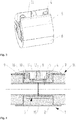
- Fig. 1 shows the inventive insulated electric welding fitting 1.
- the outer jacket 8 surrounds the fitting 1 vapor-tight.
- the outer sheath 8 is stable and protects the fitting 1 or that insulation element 6 arranged therein.
- the exceptions 10, 11 in the outer sheath and in the insulation element serve, on the one hand, to connect to the contacts 4 of the heating element 3 the electrical current is ensured and on the other hand, the welding indicators 3 are visible, which indicate whether a weld has already been carried out or not.
- a vapor-tight connection is achieved after installation, whereby the insulation element 6 is protected from moisture and condensation can be avoided.
- Fig. 2 shows a longitudinal section through the inventive electric welding fitting 1.
- the fitting 1 includes a Elektroschweissmuffe 2, preferably for cost reasons, a conventional electric welding sleeve 2 can be used.
- the electric welding sleeve 2 has at each connecting piece, which is to be connected to an end region 15 of the pipeline, a heating element 3, which is preferably formed by a Walkerdrahtwicklung 3.
- a heating element 3 which is preferably formed by a Walkerdrahtwicklung 3.
- each heating element 3 has its own contact 4.
- the insulating element 6 is arranged on the outer circumference 7 of the electric welding sleeve 2, the insulating element 6 is arranged. Preferably, it is fitted accurately around the electric welding sleeve 2, whereby an optimal insulation is achieved. For example. by means of a band (not shown) or an alternative fastening means, the insulating element 6 is fixed to the electric welding sleeve 2.
- the insulating element 6 preferably consists of two shells, which are preferably designed as half-shells. These are placed around the electric welding sleeve 2 and, for example, by means of a belt (not shown) fixed. So that the insulation element 6 can be placed accurately around the electrofusion socket 2, the insulation element 6 has exceptions 11, which make the contacts 4 and welding indicators 5 of the electrofusion socket 2 accessible and visible.
- an outer jacket 8 is arranged to the insulating element 6, which is preferably formed of rigid polyurethane foam. This is stable and forms a vapor-tight envelope.
- the outer sheath 8 also has exceptions 10 to also allow access and the view to the contacts 4 and 5 welding.
- the outer jacket 8 is produced by molding the insulating element 6, which is arranged on the outer circumference 7 of the electric welding sleeve 2.
- the outer jacket 8 is preferably made of PUR or polyurea / PUR hybrid.
- the outer shell 8 has protrusion lips 9, which protrude beyond the end faces 13 of the insulation element 6, whereby an optimal tightness is achieved when installed in the piping system.
- a nose (16) is arranged, which runs along the inner circumference of the supernatant lip (9). It serves for better sealing and better adhesion between the overhang lip (9) and the end region of the pre-insulated pipeline (14).
- Fig. 3 represents the electric welding fitting 1 according to the invention without the cast outer jacket. It can be clearly seen that the insulating element 6 is formed from several parts. The embodiment shown here has two half shells, which is considered a preferred embodiment, but also a different division is possible.
- inventive insulated electric welding fittings 1 are conceivable, which are made by the skinning process or RIM process, where the insulation element 6 is attached by foaming by foaming between the inner electric welding sleeve 2 and the outer shell 8, the previously applied to the mold or tool.
- Fig. 4 an insulated electric welding fitting 1 according to the invention is shown, which is already mounted in the pipeline system.
- the end portions of a pre-insulated pipe 14 have over a certain section no insulation and no outer tube, either by stripping or that the tailpipes have already been made.
- the end portions of the inner tubes 15 are inserted on both sides up to the stop 12 in the electric welding sleeve 2 of the inventive insulated electrofusion fitting 1. It can be clearly seen that the supernatant lips 9 protrude beyond the outer tube of the pre-insulated pipe 14 and thus ensure the vapor-tightness.
Landscapes
- Engineering & Computer Science (AREA)
- Mechanical Engineering (AREA)
- General Engineering & Computer Science (AREA)
- Lining Or Joining Of Plastics Or The Like (AREA)
- Branch Pipes, Bends, And The Like (AREA)
Description
- Die Erfindung betrifft ein isoliertes Elektroschweissfitting zur Verbindung von Endbereichen von Rohrleitungen aus thermoplastischem Kunststoff insbesondere von vorisolierten Rohrleitungen und dessen Herstellverfahren beinhaltend eine Elektroschweissmuffe, wobei die Elektroschweissmuffe mindestens ein elektrisches Heizelement aufweist, wobei das Heizelement vorzugsweise als Heizdrahtwicklung ausgebildet ist, mindestens einen Kontakt zur Zuführung des elektrischen Stroms, mindestens eine Schweissanzeige und ein Isolationselement, wobei das Isolationselement am Aussenumfang der Elektroschweissmuffe angeordnet ist.
- Bei Anwendungen bei denen eine gute Dämmung des Mediums in der Rohrleitung gegenüber den Umgebungsbedingungen benötigt wird, werden meist vorisolierte Rohrleitungen eingesetzt. Bspw. werden solch vorisolierte Rohrleitungen für den Transport bei Kälteträgermedien eingesetzt. Um das Medium transportierende Rohr ist meist eine isolierende Dämmschicht angeordnet, welche von einer Aussenhaut umgeben ist die zum Schutz der Dämmschicht gegen äussere Einflüsse wie bspw. Feuchtigkeit dient. Der Aussenmantel kann auch durch ein konzentrisch angeordnetes Aussenrohr gebildet werden.
- Das Verbinden solcher vorisolierter Rohrleitungen ist entsprechend aufwendig da an den zu verbindenden Enden die Isolation erst entfernt werden muss und nach dem Verbinden mit einem Rohrverbindungsformteil die Isolation wieder manuell angebracht werden muss.
- Die
EP 1 909 018 B1 offenbart ein Rohrverbindungsformteil mit thermischer Isolierung. Beim Anbringen dieses Rohrverbindungsformteils ist ein Isolieren nach dem Einbau in das Rohrleitungssystem nicht mehr nötig da die Isolation bereits am Rohrverbindungsformteil angeordnet ist, wodurch der Aufwand für die nachträgliche Isolierung eingespart werden kann. - Nachteilig an diesem Rohrverbindungsformteil ist jedoch dass dieses Formteil nur als klebbares Verbindungsformteil vorliegt.
- Bei manchen Anwendungen wird eine Verbindung von Rohrleitungen durch Elektroschweissmuffen vorausgesetzt. Das heisst, dass eine Elektroschweissmuffe zur Verbindung benötigt wird. Solche Elektroschweissmuffen sind bekannt z.B.
CH 689 024 A5 - Dokument
EP 0 048 065 A1 offenbart ein isoliertes Fitting zur Verbindung von Endbereichen von Rohrleitungen aus thermoplastischem Kunststoff, insbesondere von Rohrleitungen, beinhaltend eine Muffe, wobei die Muffe mindestens ein elektrisches Heizelement aufweist, mindestens einen Kontakt zur Zuführung des elektrischen Stroms, ein Isolationselement, wobei das Isolationselement am Aussenumfang der Muffe angeordnet ist, wobei das isolierte Fitting einen Aussenmantel aus Kunststoff aufweist. - Dokumente
EP 0 075 901 A1 ,CH 662 402 A5 EP 2 525 129 A2 offenbaren ein Elektroschweissfitting mit einer Schweissanzeige. - Es ist Aufgabe der Erfindung ein isoliertes Elektroschweissfitting und ein damit verbundenes Verfahren zur Herstellung eines solchen vorzuschlagen, dass die Montagezeit verringert, wie auch eine dampfdichte Verbindung zwischen dem isolierten Elektroschweissfitting und der vorisolierten Rohrleitung gebildet wird.
Die Aufgabe wird erfindungsgemäss dadurch gelöst, dass das isolierte Elektroschweissfitting einen Aussenmantel aus Kunststoff aufweist, wobei der Aussenmantel durch Umgiessen des Isolationselements gebildet wird.
Das erfindungsgemässe isolierte Elektroschweissfitting beinhaltet eine Elektroschweissmuffe, wobei vorzugsweise eine herkömmliche Elektroschweissmuffe verwendet wird. Unter einer herkömmlichen Elektroschweissmuffe ist eine Elektroschweissmuffe zu verstehen, die aus dem Stand der Technik bekannt ist und zur Verbindung der Rohrleitungsenden aus thermoplastischem Kunststoff dient. Dadurch kann die Herstellung von speziellen Elektroschweissmuffen vermieden werden, wodurch die Herstellkosten für das isolierte Elektroschweissfitting optimiert werden können. Natürlich können aber auch speziell für das isolierte Elektroschweissfitting Elektroschweissmuffen hergestellt werden was den Vorteil hätte, dass gewisse konstruktive Features angebracht werden könnten, die bspw. das Anbringen des Isolationselements oder auch den Vorgang des Umgiessens oder des Skinning-Verfahrens bzw. RIM-Verfahren optimieren könnten. Die Elektroschweissmuffe weist mindestens ein Heizelement auf, wobei vorzugsweise eine Heizdrahtwicklung dazu eingesetzt wird. Zur Zuführung des elektrischen Stroms weist die Elektroschweissmuffe einen Kontakt auf, vorzugsweise weist jedes Heizelement einen eigenen Kontakt auf. Zur Anzeige ob eine Schweissung stattgefunden hat, weist die Elektroschweissmuffe eine Schweissanzeige auf. Auch hier ist es von Vorteil, wenn bei jedem Heizelement eine Schweissanzeige angeordnet ist, wodurch sich erkennen lässt, welche Schweissung durchgeführt wurde und welche nicht. - Zur Dämmung ist um die Elektroschweissmuffe ein Isolationselement angeordnet. Dadurch wird das Medium im Rohrleitungssystem gegenüber der Umgebungstemperatur isoliert bzw. das Rohrleitungssystem ist dadurch auch im Bereich von Verbindungsstellen isoliert bzw. vorisoliert.
- Das erfindungsgemässe isolierte Elektroschweissfitting weist einen Aussenmantel aus Kunststoff auf. Der Aussenmantel des isolierten Elektroschweissfittings umschliesst das Isolationselement, wodurch ein dampfdichtes isoliertes Elektroschweissfitting gebildet wird.
- Das isolierte Elektroschweissfitting wird somit komplett vorgefertigt, wodurch bei der Montage auf der Baustelle nach dem Schweissvorgang kein nachträgliches Isolieren des Verbindungsteils bzw. der Elektroschweissmuffe in Bezug auf das anzuschliessende Rohrende benötigt wird, da die Elektroschweissmuffe bereits vorisoliert ist.
- Zur Optimierung der Isolation ist es von Vorteil, wenn die Ausnahmen in der Isolation bzw. im Isolationselement für die Kontakte und die Schweissanzeigen nach dem Anbringen des isolierten Elektroschweissfittings noch isoliert werden.
- Der Aussenmantel ist um das Isolationselement gegossen oder wird durch das Skinning-Verfahren aufgebracht, auch bekannt unter RIM-Verfahren.
- Der Aussenmantel ist stabil. Das heisst, er dient auch dem Schutz des isolierten Elektroschweissfittings bzw. des Isolationselements. Das Fitting ist durch den stabilen Aussenmantel nicht einfach eindrück- oder beschädigbar. Wie bereits zuvor beschrieben, wird das erfindungsgemässe isolierte Elektroschweissfitting komplett vorgefertigt. Das heisst, dass die Elektroschweissmuffe im Werk am Aussenumfang mit dem Isolationselement versehen wird, wobei das Isolationselement vorzugsweise mittels eines Bandes oder sonstigen Befestigungsmittels an der Elektroschweissmuffe fixiert und dann mit einem Kunststoff umgossen wird, der den Aussenmantel bildet. Alternativ kann das isolierte Elektroschweissfitting auch durch das Skinning-Verfahren bzw. RIM-Verfahren hergestellt werden, wobei dann das Isolationselement durch Schäumen gebildet wird indem der in eine Form bzw. Werkzeug aufgetragene Aussenmantel aus Kunststoff und die mehr oder weniger konzentrisch dazu eingelegte Elektroschweissmuffe umschäumt bzw. der Bereich zwischen Aussenmantel und Elektroschweissmuffe ausgeschäumt wird.
- Das am Aussenumfang der Elektroschweissmuffe angeordnete Isolationselement besteht vorzugsweise aus zwei Schalen.
- Vorteilhaft ist es, wenn die Schalen jeweils als Halbschalen ausgebildet sind, dadurch lässt sich ein einfaches Anlegen um die Elektroschweissmuffe ermöglichen. Es sind auch andere Teilungen des Isolationselements vorstellbar, zu bevorzugen sind solche, wodurch sich das Isolationselement einfach um die Elektroschweissmuffe legen lässt.
- Alternativ kann das Isolationselement durch Ausschäumen des Bereichs zwischen der Elektroschweissmuffe und dem Aussenmantel gebildet werden.
- Das Isolationselement ist passgenau um die Elektroschweissmuffe angeordnet, wodurch eine optimale Dämmung erreicht wird.
- Das Isolationselement weist vorzugsweise Aussparungen für den Kontakt und die Schweissanzeige auf, dadurch wird der Zugang zum Kontakt und somit das Anschliessen des elektrischen Stroms gewährleistet, wie auch durch die Aussparung im Isolationselement für die Schweissanzeige das Erkennen ob eine Schweissung stattgefunden, hat ermöglicht wird.
- Entsprechend den Ausnahmen im Isolationselement weist auch der Aussenmantel Ausnahmen auf, wodurch der Kontakt und die Schweissanzeige zugänglich und ersichtlich sind.
- Eine bevorzugte Ausgestaltung des erfindungsgemässen isolierten Elektroschweissfittings besteht darin, dass das isolierte Elektroschweissfitting eine Überstandslippe aufweist. Die Überstandslippe ist jeweils stirnseitig angeordnet und ragt über die Stirnseite des Isolationselements hinaus.
- Die Überstandslippe dient der optimalen Abdichtung.
- Die Überstandslippen sind beidseitig des Fittings angeordnet und werden bei der Montage über die isolierten Rohrenden geschoben bzw. gestülpt, wodurch auch hier kein nachträglich zu isolierender Spalt entsteht.
- Am Innenumfang der Überstandslippe ist eine Nase angeordnet, welche sich entlang des Innenumfangs der Überstandslippe erstreckt. Sie dient der Haftung der Überstandslippe am angeschlossenen Rohrleitungsende bzw. auch einer Verbesserung der Abdichtung gegen Schmutz.
- Es hat sich gezeigt, dass der Aussenmantel vorzugsweise aus PUR oder Polyurea / PUR-Hybrid herzustellen ist.
- Der bevorzugte Werkstoff für das Isolationselement ist PUR-Hartschaum.
- Das erfindungsgemässe isolierte Elektroschweissfitting kann neben einem geraden Fitting bzw. Verbindungsformteil auch als T-Stück oder Y-Stück zum Verbinden von drei Rohrleitungsenden oder als Winkelstück wie auch als Bogensegment ausgebildet sein. Ebenso ist die vorliegende Erfindung als Reduzierstück umsetzbar, welches auch kombinierbar mit jeglicher zuvor erwähnten Formgestaltung ist.
- Das Verfahren zur Herstellung eines erfindungsgemässen isolierten Elektroschweissfitting zur Verbindung von Endbereichen von Rohrleitungen aus thermoplastischem Kunststoff, insbesondere von vorisolierten Rohrleitungen beinhaltet eine Elektroschweissmuffe, wobei die Elektroschweissmuffe vorzugsweise durch eine herkömmliche aus dem Stand der Technik bekannte Elektroschweissmuffe gebildet wird. Wie zuvor erwähnt kann aber auch eine spezifisch für diese Anwendung hergestellte Elektroschweissmuffe eingesetzt werden.
- Die zuvor beschriebenen Ausführungen sind entsprechend auch auf das Verfahren umsetzbar.
- Am Aussenumfang der Elektroschweissmuffe wird ein passgenaues Isolationselement angebracht, wodurch eine optimale Isolierung erreicht wird. Um das Isolationselement wird ein Aussenmantel aus Kunststoff durch Umgiessen aufgebracht.
- Alternativ kann der Aussenmantel durch das Skinning-Verfahren bzw. RIM-Verfahren hergestellt werden, wodurch ebenfalls ein stabiler und dampfdichter Aussenmantel gebildet wird. Dazu wird die Form bzw. das Werkzeug, welches der Aussenkontur des isolierten Elektroschweissfittings entspricht mit Kunststoff beschichtet, der dann den Aussenmantel bildet. Dann wird die Elektroschweissmuffe in die Form eingelegt und der Bereich zwischen Elektroschweissmuffe und Aussenmantel umschäumt. Das Isolationselement wird vorzugsweise mittels eines Bandes an der Elektroschweissmuffe fixiert, wobei auch andere Befestigungsmittel denkbar sind.
- Ein Ausführungsbeispiel der Erfindung wird anhand der Figuren beschrieben, wobei sich die Erfindung nicht nur auf das Ausführungsbeispiel beschränkt. Es zeigen:
- Fig. 1
- eine dreidimensionale Ansicht eines erfindungsgemässen isolierten Elektroschweissfittings,
- Fig. 2
- einen Längsschnitt durch ein erfindungsgemässes isoliertes Elektroschweissfitting,
- Fig. 3
- eine dreidimensionale Ansicht eines erfindungsgemässen isolierten Elektroschweissfittings ohne Aussenmantel und
- Fig. 4
- einen Längsschnitt durch ein erfindungsgemässes isoliertes Elektroschweissfitting, das bereits in ein isoliertes Rohrleitungssystem eingebaut ist.
-
Fig. 1 zeigt das erfindungsgemässe isolierte Elektroschweissfitting 1. Der Aussenmantel 8 umgibt das Fitting 1 dampfdicht. Zudem ist der Aussenmantel 8 stabil und schützt das Fitting 1 bzw. dass darin angeordnete Isolationselement 6. Die Ausnahmen 10, 11 im Aussenmantel sowie im Isolationselement dienen dazu, dass einerseits der Zugang zu den Kontakten 4 des Heizelements 3 zum Anschliessen des elektrischen Stroms gewährleistet ist und andererseits die Schweissanzeigen 3 sichtbar sind, welche anzeigen ob eine Schweissung bereits durchgeführt wurde oder nicht. - Die Überstandslippen 9, welche beidseitig des erfindungsgemässen isolierten Elektroschweissfittings 1 angeordnet sind ragen über die Stirnseiten 13 des Isolationselements 6 hinaus, welche vorzugsweise mit den Stirnseiten der Elektroschweissmuffe 2 bündig sind bzw. eine Ebene bilden. Durch die Überstandslippen 9 wird nach der Montage eine dampfdichte Verbindung erzielt, wodurch das Isolationselement 6 vor Feuchtigkeit geschützt ist und eine Kondensation vermieden werden kann.
-
Fig. 2 zeigt einen Längsschnitt durch das erfindungsgemässe Elektroschweissfitting 1. Das Fitting 1 beinhaltet eine Elektroschweissmuffe 2, wobei vorzugsweise aus Kostengründen eine herkömmliche Elektroschweissmuffe 2 eingesetzt werden kann. Die Elektroschweissmuffe 2 weist bei jedem Anschlussstutzen, welcher mit einem Endbereich 15 der Rohrleitung zu verbinden ist, ein Heizelement 3 auf, welches vorzugsweise durch eine Heizdrahtwicklung 3 gebildet wird. Zur Zuführung des elektrischen Stromes dienen Kontakte 4, vorzugsweise weist jedes Heizelement 3 seinen eigenen Kontakt 4 auf. Zudem weist die Elektroschweissmuffe 2 Schweissanzeigen 5 auf, wobei ebenfalls jedes Heizelement 3 eine entsprechende Anzeige 5 aufweist. - Am Aussenumfang 7 der Elektroschweissmuffe 2 ist das Isolationselement 6 angeordnet. Vorzugsweise ist es passgenau um die Elektroschweissmuffe 2 angebracht, wodurch eine optimale Dämmung erzielt wird. Bspw. mittels eines Bandes (nicht dargestellt) oder eines alternativen Befestigungsmittels wird das Isolationselement 6 an der Elektroschweissmuffe 2 fixiert. Das Isolationselement 6 besteht vorzugsweise aus zwei Schalen, die vorzugsweise als Halbschalen ausgebildet sind. Diese werden um die Elektroschweissmuffe 2 gelegt und bspw. mittels eines Bandes (nicht dargestellt) fixiert. Damit das Isolationselement 6 passgenau um die Elektroschweissmuffe 2 gelegt werden kann, weist das Isolationselement 6 Ausnahmen 11 auf, welche die Kontakte 4 und Schweissanzeigen 5 der Elektroschweissmuffe 2 zugänglich und ersichtlich machen.
- Um das Isolationselement 6, welches vorzugsweise aus PUR-Hartschaum gebildet ist, ist ein Aussenmantel 8 angeordnet. Dieser ist stabil und bildet eine dampfdichte Hülle. Der Aussenmantel 8 weist ebenfalls Ausnahmen 10 auf um ebenfalls den Zugang sowie die Sicht zu den Kontakten 4 und Schweissanzeigen 5 zu ermöglichen. Der Aussenmantel 8 wird durch Umgiessen des Isolationselements 6, welches am Aussenumfang 7 der Elektroschweissmuffe 2 angeordnet ist erzeugt.
- Der Aussenmantel 8 ist vorzugsweise aus PUR oder Polyurea/PUR-Hybrid.
- Der Aussenmantel 8 weist Überstandslippen 9 auf, welche über die Stirnseiten 13 des Isolationselements 6 hinausragen, wodurch beim Einbau in das Rohrleitungssystem eine optimale Dichtheit erreicht wird. Am Innenumfang der Überstandslippe (9) ist eine Nase (16) angeordnet, welche entlang des Innenumfangs der Überstandslippe (9) verläuft. Sie dient einer bessern Abdichtung sowie einer besseren Haftung zwischen der Überstandslippe (9) und dem Endbereich der vorisolierten Rohrleitung (14)
-
Fig. 3 stellt das erfindungsgemässe Elektroschweissfitting 1 ohne den gegossenen Aussenmantel dar. Dabei ist gut erkennbar, dass das Isolationselement 6 aus mehreren Teilen gebildet wird. Die hier dargestellte Ausführungsform weist zwei Halbschalen auf, was als bevorzugte Ausführungsform gilt, wobei aber auch eine andere Teilung möglich ist. - Wie zuvor erwähnt, sind auch erfindungsgemässe isolierte Elektroschweissfittings 1 denkbar, die durch das Skinning-Verfahren bzw. RIM-Verfahren hergestellt sind, wobei dort das Isolationselement 6 durch Schäumen angebracht wird indem es zwischen die innenliegenden Elektroschweissmuffe 2 und dem Aussenmantel 8 geschäumt wird, der bereits zuvor in die Form bzw. Werkzeug aufgebracht wurde.
- In
Fig. 4 wird ein erfindungsgemässes isoliertes Elektroschweissfitting 1 aufgezeigt, das bereits im Rohrleitungssystem montiert ist. Die Endbereiche einer vorisolierten Rohrleitung 14 weisen über einen gewissen Abschnitt keine Isolation und kein Aussenrohr auf, sei es durch Abisolierung oder dass die Endrohre bereits so gefertigt wurden. Die Endbereiche der Innenrohre 15 sind beidseitig bis zum Anschlag 12 in die Elektroschweissmuffe 2 des erfindungsgemässen isolierten Elektroschweissfittings 1 eingeführt. Gut erkennbar ist, dass die Überstandslippen 9 über das Aussenrohr der vorisolierten Rohrleitung 14 ragen und so die Dampfdichtheit gewährleisten. -
- 1
- Isoliertes Elektroschweissfitting
- 2
- Elektroschweissmuffe
- 3
- Heizelement / Heizdrahtwicklung
- 4
- Kontakt
- 5
- Schweissanzeige
- 6
- Isolationselement
- 7
- Aussenumfang Elektroschweissmuffe
- 8
- Aussenmantel
- 9
- Überstandslippe
- 10
- Ausnahme in Aussenmantel
- 11
- Ausnahme in Isolationselement
- 12
- Anschlag
- 13
- Stirnseite Isolationselement
- 14
- Endbereich einer vorisolierten Rohrleitung
- 15
- Endbereich des Innerohres
- 16
- Nase
Claims (11)
- Isoliertes Elektroschweissfitting (1) zur Verbindung von Endbereichen (15) von Rohrleitungen aus thermoplastischem Kunststoff, insbesondere von vorisolierten Rohrleitungen (14) beinhaltend eine Elektroschweissmuffe (2), wobei die Elektroschweissmuffe mindestens ein elektrisches Heizelement (3) aufweist, wobei das Heizelement (3) vorzugsweise als Heizdrahtwicklung (3) ausgebildet ist, mindestens einen Kontakt (4) zur Zuführung des elektrischen Stroms, mindestens eine Schweissanzeige (5), ein Isolationselement (6), wobei das Isolationselement (6) am Aussenumfang (7) der Elektroschweissmuffe (2) angeordnet ist, wobei das isolierte Elektroschweissfitting (1) einen Aussenmantel (8) aus Kunststoff aufweist.
- Isoliertes Elektroschweissfitting (1) nach Anspruch 1, dadurch gekennzeichnet, dass der Aussenmantel (8) stabil ausgebildet ist.
- Isoliertes Elektroschweissfitting (1) nach einem der Ansprüche 1 oder 2, dadurch gekennzeichnet, dass das isolierte Elektroschweissfitting (1) komplett vorgefertigt ist.
- Isoliertes Elektroschweissfitting (1) nach einem der Ansprüche 1 bis 3, dadurch gekennzeichnet, dass das Isolationselement (6) aus mindestens zwei Schalen vorzugsweise Halbschalen gebildet ist.
- Isoliertes Elektroschweissfitting (1) nach einem der Ansprüche 1 bis 2, dadurch gekennzeichnet, dass das Isolationselement (6) durch Ausschäumen des Bereichs zwischen der Elektroschweissmuffe (2) und dem Aussenmantel (8) gebildet ist.
- Isoliertes Elektroschweissfitting (1) nach einem der Ansprüche 1 bis 5, dadurch gekennzeichnet, dass das Isolationselement (6) Aussparungen (11) für den Kontakt und die Schweissanzeige aufweist.
- Isoliertes Elektroschweissfitting (1) nach einem der Ansprüche 1 bis 6, dadurch gekennzeichnet, dass der Aussenmantel (8) des isolierten Elektroschweissfittings (1) eine Überstandslippe (9) aufweist, wobei die Überstandslippe (9) über die Stirnseite (13) des Isolationselements (6) hinaus ragt.
- Isoliertes Elektroschweissfitting (1) nach Anspruch 7, dadurch gekennzeichnet, dass die Überstandslippe (9) am Innenumfang eine Nase (16) aufweist, wobei sich die Nase (16) über den Innenumfang der Überstandlippe (9) erstreckt.
- Isoliertes Elektroschweissfitting (1) nach einem der Ansprüche 1 bis 8, dadurch gekennzeichnet, dass der Aussenmantel (8) des isolierten Elektroschweissfittings (1) aus PUR oder Polyurea / PUR-Hyprid ist.
- Isoliertes Elektroschweissfitting (1) nach einem der vorangehenden Ansprüche, dadurch gekennzeichnet, dass das Isolationselement (1) aus PUR-Hartschaum ist.
- Verfahren zur Herstellung eines isolierten Elektroschweissfittings (1) nach Anspruch 1, wobei die Elektroschweissmuffe (2) vorzugsweise durch eine herkömmliche Elektroschweissmuffe gebildet wird und ein passgenaues Isolationselement (6) am Aussenumfang (7) der Elektroschweissmuffe (2) angeordnet wird, wobei der Aussenmantel (8) durch Umgiessen des an der Elektroschweissmuffe (2) angeordnetes Isolationselements (6) oder durch das Skinning-Verfahren bzw. RIM gebildet wird.
Priority Applications (2)
| Application Number | Priority Date | Filing Date | Title |
|---|---|---|---|
| EP14197261.2A EP3031599B1 (de) | 2014-12-11 | 2014-12-11 | Isoliertes Elektroschweissfitting |
| ES14197261T ES2728050T3 (es) | 2014-12-11 | 2014-12-11 | Pieza de conexión para electrofusión aislada |
Applications Claiming Priority (1)
| Application Number | Priority Date | Filing Date | Title |
|---|---|---|---|
| EP14197261.2A EP3031599B1 (de) | 2014-12-11 | 2014-12-11 | Isoliertes Elektroschweissfitting |
Publications (2)
| Publication Number | Publication Date |
|---|---|
| EP3031599A1 EP3031599A1 (de) | 2016-06-15 |
| EP3031599B1 true EP3031599B1 (de) | 2019-02-27 |
Family
ID=52292610
Family Applications (1)
| Application Number | Title | Priority Date | Filing Date |
|---|---|---|---|
| EP14197261.2A Active EP3031599B1 (de) | 2014-12-11 | 2014-12-11 | Isoliertes Elektroschweissfitting |
Country Status (2)
| Country | Link |
|---|---|
| EP (1) | EP3031599B1 (de) |
| ES (1) | ES2728050T3 (de) |
Family Cites Families (6)
| Publication number | Priority date | Publication date | Assignee | Title |
|---|---|---|---|---|
| NL8005161A (nl) * | 1980-09-15 | 1982-04-01 | Wavin Bv | Gelijmde buisverbinding. |
| DE8213761U1 (de) * | 1981-09-29 | 1984-04-12 | Von Roll AG, 4563 Gerlafingen | Rohrverbindung fuer rohrleitungen aus isolierten doppelrohren |
| CH662402A5 (en) * | 1981-11-18 | 1987-09-30 | Von Roll Ag | Pipe connection for pipelines which are provided with insulation |
| DE4332196C2 (de) | 1993-09-22 | 1996-09-19 | Fischer Georg Rohrleitung | Schweißmuffe aus thermoplastischem Material |
| EP1909018B1 (de) | 2006-10-05 | 2014-08-20 | Georg Fischer Rohrleitungssysteme AG | Rohrverbindungsformteil mit thermischer Isolierung und Verfahren zur Herstellung des Rohrverbindungsformteiles |
| CH704994B1 (fr) * | 2011-05-20 | 2016-03-15 | Plco Pipelines Construction S A | Procédé de raccordement de conduits de chauffage urbain et manchon de raccordement pour la mise en œuvre de ce procédé. |
-
2014
- 2014-12-11 ES ES14197261T patent/ES2728050T3/es active Active
- 2014-12-11 EP EP14197261.2A patent/EP3031599B1/de active Active
Non-Patent Citations (1)
| Title |
|---|
| None * |
Also Published As
| Publication number | Publication date |
|---|---|
| EP3031599A1 (de) | 2016-06-15 |
| ES2728050T3 (es) | 2019-10-22 |
Similar Documents
| Publication | Publication Date | Title |
|---|---|---|
| EP0075901B1 (de) | Verfahren zum Verbinden von Mantelrohren zweier isolierter Leitungselemente und Verbindungsrohr zur Durchführung des Verfahrens | |
| EP2641006B1 (de) | Konfektionierte elektrisch beheizbare medienleitung sowie verfahren zum herstellen einer solchen medienleitung | |
| DE202007010502U1 (de) | Konfektionierte Medienleitung | |
| DE3808383A1 (de) | Leitungsverbindung | |
| EP2192655B1 (de) | Dichte Steckerverbindung für Hochspannungskabel im Automobilbau | |
| EP2897778B1 (de) | Verfahren zur herstellung eines kabelsatzes sowie kabelsatz | |
| DE2341112C3 (de) | Verschlußgehäuse für mindestens ein Ende eines elektrischen Kabels | |
| EP3031599A1 (de) | Isoliertes Elektroschweissfitting | |
| DE102015112519A1 (de) | Windschutzhülle und eine Steckverbindungsvorrichtung mit einer solchen | |
| EP3115671B1 (de) | Transition fitting | |
| DE20020563U1 (de) | Vorrichtung zur Isolation von Mehrfachrohrleitungen | |
| DE102015117020B4 (de) | Verfahren zum Herstellen einer Leitungsabdichtung eines Leitungsstrangs und Verfahren zur Herstellung einer gedichteten Leitungsverbindung | |
| DE202014003776U1 (de) | Kunststoffrohr | |
| EP0396927B1 (de) | Anschluss- bzw. Verbindungselement für Kabelbäume | |
| EP2947368A1 (de) | Isolierelement bzw. Isoliersystem zur Ummantelung eines Körpers | |
| DE7117532U (de) | Wärmeschrumpfbare Manschette | |
| DE3738203C2 (de) | ||
| EP1975499A2 (de) | Vorrichtung zur Herstellung eines Abzweigs an einer verlegten Rohrleitung | |
| EP2873513B1 (de) | Elektroschweissrohrverbindungsformteil | |
| EP2985133B1 (de) | Verfahren zur nachumhüllung eines rohrformteils | |
| EP0045940B1 (de) | Isolierkappe für Rohrleitungsarmaturen und Werkzeugsatz zum Herstellen derselben | |
| DE2636905C2 (de) | Verfahren zur Herstellung einer gegen Korrosion geschützten Rohrverbindung | |
| DE19549505C2 (de) | Flexible Hauseinführung für eine Gasleitung | |
| DE3442674A1 (de) | Verfahren zum nachisolieren eines bogens einer waermeisolierten rohrleitung | |
| EP2624036B1 (de) | Verlegeschale für Kabelverbundstränge, insbesondere Lichtwellenleitkabelverbundstränge |
Legal Events
| Date | Code | Title | Description |
|---|---|---|---|
| PUAI | Public reference made under article 153(3) epc to a published international application that has entered the european phase |
Free format text: ORIGINAL CODE: 0009012 |
|
| AK | Designated contracting states |
Kind code of ref document: A1 Designated state(s): AL AT BE BG CH CY CZ DE DK EE ES FI FR GB GR HR HU IE IS IT LI LT LU LV MC MK MT NL NO PL PT RO RS SE SI SK SM TR |
|
| AX | Request for extension of the european patent |
Extension state: BA ME |
|
| STAA | Information on the status of an ep patent application or granted ep patent |
Free format text: STATUS: REQUEST FOR EXAMINATION WAS MADE |
|
| 17P | Request for examination filed |
Effective date: 20161129 |
|
| RBV | Designated contracting states (corrected) |
Designated state(s): AL AT BE BG CH CY CZ DE DK EE ES FI FR GB GR HR HU IE IS IT LI LT LU LV MC MK MT NL NO PL PT RO RS SE SI SK SM TR |
|
| GRAP | Despatch of communication of intention to grant a patent |
Free format text: ORIGINAL CODE: EPIDOSNIGR1 |
|
| STAA | Information on the status of an ep patent application or granted ep patent |
Free format text: STATUS: GRANT OF PATENT IS INTENDED |
|
| RIC1 | Information provided on ipc code assigned before grant |
Ipc: B29C 65/34 20060101AFI20180910BHEP Ipc: F16L 59/20 20060101ALI20180910BHEP Ipc: F16L 47/03 20060101ALI20180910BHEP |
|
| INTG | Intention to grant announced |
Effective date: 20180928 |
|
| GRAS | Grant fee paid |
Free format text: ORIGINAL CODE: EPIDOSNIGR3 |
|
| GRAA | (expected) grant |
Free format text: ORIGINAL CODE: 0009210 |
|
| STAA | Information on the status of an ep patent application or granted ep patent |
Free format text: STATUS: THE PATENT HAS BEEN GRANTED |
|
| AK | Designated contracting states |
Kind code of ref document: B1 Designated state(s): AL AT BE BG CH CY CZ DE DK EE ES FI FR GB GR HR HU IE IS IT LI LT LU LV MC MK MT NL NO PL PT RO RS SE SI SK SM TR |
|
| REG | Reference to a national code |
Ref country code: GB Ref legal event code: FG4D Free format text: NOT ENGLISH |
|
| REG | Reference to a national code |
Ref country code: CH Ref legal event code: EP |
|
| REG | Reference to a national code |
Ref country code: AT Ref legal event code: REF Ref document number: 1100710 Country of ref document: AT Kind code of ref document: T Effective date: 20190315 |
|
| REG | Reference to a national code |
Ref country code: IE Ref legal event code: FG4D Free format text: LANGUAGE OF EP DOCUMENT: GERMAN |
|
| REG | Reference to a national code |
Ref country code: DE Ref legal event code: R096 Ref document number: 502014010933 Country of ref document: DE |
|
| REG | Reference to a national code |
Ref country code: NL Ref legal event code: FP |
|
| REG | Reference to a national code |
Ref country code: SE Ref legal event code: TRGR |
|
| REG | Reference to a national code |
Ref country code: LT Ref legal event code: MG4D |
|
| PG25 | Lapsed in a contracting state [announced via postgrant information from national office to epo] |
Ref country code: PT Free format text: LAPSE BECAUSE OF FAILURE TO SUBMIT A TRANSLATION OF THE DESCRIPTION OR TO PAY THE FEE WITHIN THE PRESCRIBED TIME-LIMIT Effective date: 20190627 Ref country code: FI Free format text: LAPSE BECAUSE OF FAILURE TO SUBMIT A TRANSLATION OF THE DESCRIPTION OR TO PAY THE FEE WITHIN THE PRESCRIBED TIME-LIMIT Effective date: 20190227 Ref country code: NO Free format text: LAPSE BECAUSE OF FAILURE TO SUBMIT A TRANSLATION OF THE DESCRIPTION OR TO PAY THE FEE WITHIN THE PRESCRIBED TIME-LIMIT Effective date: 20190527 Ref country code: LT Free format text: LAPSE BECAUSE OF FAILURE TO SUBMIT A TRANSLATION OF THE DESCRIPTION OR TO PAY THE FEE WITHIN THE PRESCRIBED TIME-LIMIT Effective date: 20190227 |
|
| PG25 | Lapsed in a contracting state [announced via postgrant information from national office to epo] |
Ref country code: HR Free format text: LAPSE BECAUSE OF FAILURE TO SUBMIT A TRANSLATION OF THE DESCRIPTION OR TO PAY THE FEE WITHIN THE PRESCRIBED TIME-LIMIT Effective date: 20190227 Ref country code: BG Free format text: LAPSE BECAUSE OF FAILURE TO SUBMIT A TRANSLATION OF THE DESCRIPTION OR TO PAY THE FEE WITHIN THE PRESCRIBED TIME-LIMIT Effective date: 20190527 Ref country code: RS Free format text: LAPSE BECAUSE OF FAILURE TO SUBMIT A TRANSLATION OF THE DESCRIPTION OR TO PAY THE FEE WITHIN THE PRESCRIBED TIME-LIMIT Effective date: 20190227 Ref country code: IS Free format text: LAPSE BECAUSE OF FAILURE TO SUBMIT A TRANSLATION OF THE DESCRIPTION OR TO PAY THE FEE WITHIN THE PRESCRIBED TIME-LIMIT Effective date: 20190627 Ref country code: GR Free format text: LAPSE BECAUSE OF FAILURE TO SUBMIT A TRANSLATION OF THE DESCRIPTION OR TO PAY THE FEE WITHIN THE PRESCRIBED TIME-LIMIT Effective date: 20190528 Ref country code: LV Free format text: LAPSE BECAUSE OF FAILURE TO SUBMIT A TRANSLATION OF THE DESCRIPTION OR TO PAY THE FEE WITHIN THE PRESCRIBED TIME-LIMIT Effective date: 20190227 |
|
| REG | Reference to a national code |
Ref country code: ES Ref legal event code: FG2A Ref document number: 2728050 Country of ref document: ES Kind code of ref document: T3 Effective date: 20191022 |
|
| PG25 | Lapsed in a contracting state [announced via postgrant information from national office to epo] |
Ref country code: EE Free format text: LAPSE BECAUSE OF FAILURE TO SUBMIT A TRANSLATION OF THE DESCRIPTION OR TO PAY THE FEE WITHIN THE PRESCRIBED TIME-LIMIT Effective date: 20190227 Ref country code: SK Free format text: LAPSE BECAUSE OF FAILURE TO SUBMIT A TRANSLATION OF THE DESCRIPTION OR TO PAY THE FEE WITHIN THE PRESCRIBED TIME-LIMIT Effective date: 20190227 Ref country code: DK Free format text: LAPSE BECAUSE OF FAILURE TO SUBMIT A TRANSLATION OF THE DESCRIPTION OR TO PAY THE FEE WITHIN THE PRESCRIBED TIME-LIMIT Effective date: 20190227 Ref country code: AL Free format text: LAPSE BECAUSE OF FAILURE TO SUBMIT A TRANSLATION OF THE DESCRIPTION OR TO PAY THE FEE WITHIN THE PRESCRIBED TIME-LIMIT Effective date: 20190227 Ref country code: CZ Free format text: LAPSE BECAUSE OF FAILURE TO SUBMIT A TRANSLATION OF THE DESCRIPTION OR TO PAY THE FEE WITHIN THE PRESCRIBED TIME-LIMIT Effective date: 20190227 Ref country code: RO Free format text: LAPSE BECAUSE OF FAILURE TO SUBMIT A TRANSLATION OF THE DESCRIPTION OR TO PAY THE FEE WITHIN THE PRESCRIBED TIME-LIMIT Effective date: 20190227 |
|
| REG | Reference to a national code |
Ref country code: DE Ref legal event code: R097 Ref document number: 502014010933 Country of ref document: DE |
|
| PG25 | Lapsed in a contracting state [announced via postgrant information from national office to epo] |
Ref country code: SM Free format text: LAPSE BECAUSE OF FAILURE TO SUBMIT A TRANSLATION OF THE DESCRIPTION OR TO PAY THE FEE WITHIN THE PRESCRIBED TIME-LIMIT Effective date: 20190227 Ref country code: PL Free format text: LAPSE BECAUSE OF FAILURE TO SUBMIT A TRANSLATION OF THE DESCRIPTION OR TO PAY THE FEE WITHIN THE PRESCRIBED TIME-LIMIT Effective date: 20190227 |
|
| PLBE | No opposition filed within time limit |
Free format text: ORIGINAL CODE: 0009261 |
|
| STAA | Information on the status of an ep patent application or granted ep patent |
Free format text: STATUS: NO OPPOSITION FILED WITHIN TIME LIMIT |
|
| PGFP | Annual fee paid to national office [announced via postgrant information from national office to epo] |
Ref country code: SE Payment date: 20191219 Year of fee payment: 6 |
|
| 26N | No opposition filed |
Effective date: 20191128 |
|
| PG25 | Lapsed in a contracting state [announced via postgrant information from national office to epo] |
Ref country code: SI Free format text: LAPSE BECAUSE OF FAILURE TO SUBMIT A TRANSLATION OF THE DESCRIPTION OR TO PAY THE FEE WITHIN THE PRESCRIBED TIME-LIMIT Effective date: 20190227 |
|
| PGFP | Annual fee paid to national office [announced via postgrant information from national office to epo] |
Ref country code: ES Payment date: 20200121 Year of fee payment: 6 |
|
| REG | Reference to a national code |
Ref country code: BE Ref legal event code: MM Effective date: 20191231 |
|
| PG25 | Lapsed in a contracting state [announced via postgrant information from national office to epo] |
Ref country code: MC Free format text: LAPSE BECAUSE OF FAILURE TO SUBMIT A TRANSLATION OF THE DESCRIPTION OR TO PAY THE FEE WITHIN THE PRESCRIBED TIME-LIMIT Effective date: 20190227 |
|
| PG25 | Lapsed in a contracting state [announced via postgrant information from national office to epo] |
Ref country code: LU Free format text: LAPSE BECAUSE OF NON-PAYMENT OF DUE FEES Effective date: 20191211 Ref country code: IE Free format text: LAPSE BECAUSE OF NON-PAYMENT OF DUE FEES Effective date: 20191211 |
|
| PG25 | Lapsed in a contracting state [announced via postgrant information from national office to epo] |
Ref country code: BE Free format text: LAPSE BECAUSE OF NON-PAYMENT OF DUE FEES Effective date: 20191231 |
|
| PG25 | Lapsed in a contracting state [announced via postgrant information from national office to epo] |
Ref country code: CY Free format text: LAPSE BECAUSE OF FAILURE TO SUBMIT A TRANSLATION OF THE DESCRIPTION OR TO PAY THE FEE WITHIN THE PRESCRIBED TIME-LIMIT Effective date: 20190227 |
|
| PG25 | Lapsed in a contracting state [announced via postgrant information from national office to epo] |
Ref country code: MT Free format text: LAPSE BECAUSE OF FAILURE TO SUBMIT A TRANSLATION OF THE DESCRIPTION OR TO PAY THE FEE WITHIN THE PRESCRIBED TIME-LIMIT Effective date: 20190227 Ref country code: HU Free format text: LAPSE BECAUSE OF FAILURE TO SUBMIT A TRANSLATION OF THE DESCRIPTION OR TO PAY THE FEE WITHIN THE PRESCRIBED TIME-LIMIT; INVALID AB INITIO Effective date: 20141211 |
|
| REG | Reference to a national code |
Ref country code: SE Ref legal event code: EUG |
|
| PG25 | Lapsed in a contracting state [announced via postgrant information from national office to epo] |
Ref country code: SE Free format text: LAPSE BECAUSE OF NON-PAYMENT OF DUE FEES Effective date: 20201212 |
|
| REG | Reference to a national code |
Ref country code: ES Ref legal event code: FD2A Effective date: 20220209 |
|
| PG25 | Lapsed in a contracting state [announced via postgrant information from national office to epo] |
Ref country code: ES Free format text: LAPSE BECAUSE OF NON-PAYMENT OF DUE FEES Effective date: 20201212 |
|
| PG25 | Lapsed in a contracting state [announced via postgrant information from national office to epo] |
Ref country code: TR Free format text: LAPSE BECAUSE OF NON-PAYMENT OF DUE FEES Effective date: 20201211 Ref country code: MK Free format text: LAPSE BECAUSE OF FAILURE TO SUBMIT A TRANSLATION OF THE DESCRIPTION OR TO PAY THE FEE WITHIN THE PRESCRIBED TIME-LIMIT Effective date: 20190227 |
|
| P01 | Opt-out of the competence of the unified patent court (upc) registered |
Effective date: 20230529 |
|
| REG | Reference to a national code |
Ref country code: CH Ref legal event code: U11 Free format text: ST27 STATUS EVENT CODE: U-0-0-U10-U11 (AS PROVIDED BY THE NATIONAL OFFICE) Effective date: 20260101 |
|
| PGFP | Annual fee paid to national office [announced via postgrant information from national office to epo] |
Ref country code: DE Payment date: 20251211 Year of fee payment: 12 |
|
| PGFP | Annual fee paid to national office [announced via postgrant information from national office to epo] |
Ref country code: GB Payment date: 20251219 Year of fee payment: 12 |
|
| PGFP | Annual fee paid to national office [announced via postgrant information from national office to epo] |
Ref country code: AT Payment date: 20251222 Year of fee payment: 12 |
|
| PGFP | Annual fee paid to national office [announced via postgrant information from national office to epo] |
Ref country code: IT Payment date: 20251223 Year of fee payment: 12 |
|
| PGFP | Annual fee paid to national office [announced via postgrant information from national office to epo] |
Ref country code: NL Payment date: 20251219 Year of fee payment: 12 Ref country code: FR Payment date: 20251223 Year of fee payment: 12 |
|
| PGFP | Annual fee paid to national office [announced via postgrant information from national office to epo] |
Ref country code: CH Payment date: 20260101 Year of fee payment: 12 |