EP3031040B1 - Garment with an emergency device and associated emergency method - Google Patents
Garment with an emergency device and associated emergency method Download PDFInfo
- Publication number
- EP3031040B1 EP3031040B1 EP14771391.1A EP14771391A EP3031040B1 EP 3031040 B1 EP3031040 B1 EP 3031040B1 EP 14771391 A EP14771391 A EP 14771391A EP 3031040 B1 EP3031040 B1 EP 3031040B1
- Authority
- EP
- European Patent Office
- Prior art keywords
- garment
- smartphone
- user
- sensors
- processing unit
- Prior art date
- Legal status (The legal status is an assumption and is not a legal conclusion. Google has not performed a legal analysis and makes no representation as to the accuracy of the status listed.)
- Active
Links
- 238000000034 method Methods 0.000 title claims description 15
- 238000012545 processing Methods 0.000 claims description 22
- 238000004891 communication Methods 0.000 claims description 19
- 230000000694 effects Effects 0.000 claims description 18
- 238000012544 monitoring process Methods 0.000 claims description 8
- 230000001960 triggered effect Effects 0.000 claims description 2
- 230000001133 acceleration Effects 0.000 claims 2
- ZMHWQAHZKUPENF-UHFFFAOYSA-N 1,2-dichloro-3-(4-chlorophenyl)benzene Chemical compound C1=CC(Cl)=CC=C1C1=CC=CC(Cl)=C1Cl ZMHWQAHZKUPENF-UHFFFAOYSA-N 0.000 description 6
- 230000005540 biological transmission Effects 0.000 description 6
- 208000003443 Unconsciousness Diseases 0.000 description 4
- 230000001413 cellular effect Effects 0.000 description 3
- 230000007257 malfunction Effects 0.000 description 3
- 230000008901 benefit Effects 0.000 description 2
- 230000006378 damage Effects 0.000 description 2
- 230000006870 function Effects 0.000 description 2
- 230000001012 protector Effects 0.000 description 2
- 206010020751 Hypersensitivity Diseases 0.000 description 1
- 230000007815 allergy Effects 0.000 description 1
- 238000004458 analytical method Methods 0.000 description 1
- 230000000712 assembly Effects 0.000 description 1
- 238000000429 assembly Methods 0.000 description 1
- 239000008280 blood Substances 0.000 description 1
- 210000004369 blood Anatomy 0.000 description 1
- 230000036772 blood pressure Effects 0.000 description 1
- 238000007664 blowing Methods 0.000 description 1
- 230000008859 change Effects 0.000 description 1
- 230000001419 dependent effect Effects 0.000 description 1
- 238000001514 detection method Methods 0.000 description 1
- 238000002347 injection Methods 0.000 description 1
- 239000007924 injection Substances 0.000 description 1
- 238000009434 installation Methods 0.000 description 1
- 230000003993 interaction Effects 0.000 description 1
- 230000002452 interceptive effect Effects 0.000 description 1
- 238000002955 isolation Methods 0.000 description 1
- 230000010355 oscillation Effects 0.000 description 1
- 230000008569 process Effects 0.000 description 1
- 230000001681 protective effect Effects 0.000 description 1
- 230000004044 response Effects 0.000 description 1
- 238000012552 review Methods 0.000 description 1
- 239000000243 solution Substances 0.000 description 1
- 239000002699 waste material Substances 0.000 description 1
Images


Classifications
-
- G—PHYSICS
- G08—SIGNALLING
- G08B—SIGNALLING OR CALLING SYSTEMS; ORDER TELEGRAPHS; ALARM SYSTEMS
- G08B25/00—Alarm systems in which the location of the alarm condition is signalled to a central station, e.g. fire or police telegraphic systems
- G08B25/01—Alarm systems in which the location of the alarm condition is signalled to a central station, e.g. fire or police telegraphic systems characterised by the transmission medium
-
- A—HUMAN NECESSITIES
- A41—WEARING APPAREL
- A41D—OUTERWEAR; PROTECTIVE GARMENTS; ACCESSORIES
- A41D13/00—Professional, industrial or sporting protective garments, e.g. surgeons' gowns or garments protecting against blows or punches
- A41D13/015—Professional, industrial or sporting protective garments, e.g. surgeons' gowns or garments protecting against blows or punches with shock-absorbing means
- A41D13/018—Professional, industrial or sporting protective garments, e.g. surgeons' gowns or garments protecting against blows or punches with shock-absorbing means inflatable automatically
-
- A—HUMAN NECESSITIES
- A41—WEARING APPAREL
- A41D—OUTERWEAR; PROTECTIVE GARMENTS; ACCESSORIES
- A41D1/00—Garments
- A41D1/002—Garments adapted to accommodate electronic equipment
-
- A—HUMAN NECESSITIES
- A41—WEARING APPAREL
- A41D—OUTERWEAR; PROTECTIVE GARMENTS; ACCESSORIES
- A41D27/00—Details of garments or of their making
- A41D27/20—Pockets; Making or setting-in pockets
- A41D27/205—Pockets adapted to receive a mobile phone or other electronic equipment
-
- G—PHYSICS
- G08—SIGNALLING
- G08B—SIGNALLING OR CALLING SYSTEMS; ORDER TELEGRAPHS; ALARM SYSTEMS
- G08B25/00—Alarm systems in which the location of the alarm condition is signalled to a central station, e.g. fire or police telegraphic systems
- G08B25/01—Alarm systems in which the location of the alarm condition is signalled to a central station, e.g. fire or police telegraphic systems characterised by the transmission medium
- G08B25/016—Personal emergency signalling and security systems
-
- G—PHYSICS
- G08—SIGNALLING
- G08B—SIGNALLING OR CALLING SYSTEMS; ORDER TELEGRAPHS; ALARM SYSTEMS
- G08B29/00—Checking or monitoring of signalling or alarm systems; Prevention or correction of operating errors, e.g. preventing unauthorised operation
- G08B29/18—Prevention or correction of operating errors
- G08B29/185—Signal analysis techniques for reducing or preventing false alarms or for enhancing the reliability of the system
-
- H—ELECTRICITY
- H04—ELECTRIC COMMUNICATION TECHNIQUE
- H04M—TELEPHONIC COMMUNICATION
- H04M1/00—Substation equipment, e.g. for use by subscribers
- H04M1/72—Mobile telephones; Cordless telephones, i.e. devices for establishing wireless links to base stations without route selection
- H04M1/724—User interfaces specially adapted for cordless or mobile telephones
- H04M1/72403—User interfaces specially adapted for cordless or mobile telephones with means for local support of applications that increase the functionality
- H04M1/72418—User interfaces specially adapted for cordless or mobile telephones with means for local support of applications that increase the functionality for supporting emergency services
- H04M1/72421—User interfaces specially adapted for cordless or mobile telephones with means for local support of applications that increase the functionality for supporting emergency services with automatic activation of emergency service functions, e.g. upon sensing an alarm
-
- H—ELECTRICITY
- H04—ELECTRIC COMMUNICATION TECHNIQUE
- H04W—WIRELESS COMMUNICATION NETWORKS
- H04W4/00—Services specially adapted for wireless communication networks; Facilities therefor
- H04W4/02—Services making use of location information
-
- A—HUMAN NECESSITIES
- A41—WEARING APPAREL
- A41D—OUTERWEAR; PROTECTIVE GARMENTS; ACCESSORIES
- A41D13/00—Professional, industrial or sporting protective garments, e.g. surgeons' gowns or garments protecting against blows or punches
-
- A—HUMAN NECESSITIES
- A41—WEARING APPAREL
- A41D—OUTERWEAR; PROTECTIVE GARMENTS; ACCESSORIES
- A41D2600/00—Uses of garments specially adapted for specific purposes
- A41D2600/10—Uses of garments specially adapted for specific purposes for sport activities
- A41D2600/102—Motorcycling
-
- A—HUMAN NECESSITIES
- A42—HEADWEAR
- A42B—HATS; HEAD COVERINGS
- A42B3/00—Helmets; Helmet covers ; Other protective head coverings
- A42B3/04—Parts, details or accessories of helmets
- A42B3/0406—Accessories for helmets
- A42B3/0433—Detecting, signalling or lighting devices
- A42B3/046—Means for detecting hazards or accidents
-
- G—PHYSICS
- G08—SIGNALLING
- G08B—SIGNALLING OR CALLING SYSTEMS; ORDER TELEGRAPHS; ALARM SYSTEMS
- G08B21/00—Alarms responsive to a single specified undesired or abnormal condition and not otherwise provided for
- G08B21/02—Alarms for ensuring the safety of persons
- G08B21/04—Alarms for ensuring the safety of persons responsive to non-activity, e.g. of elderly persons
- G08B21/0407—Alarms for ensuring the safety of persons responsive to non-activity, e.g. of elderly persons based on behaviour analysis
- G08B21/043—Alarms for ensuring the safety of persons responsive to non-activity, e.g. of elderly persons based on behaviour analysis detecting an emergency event, e.g. a fall
-
- G—PHYSICS
- G08—SIGNALLING
- G08B—SIGNALLING OR CALLING SYSTEMS; ORDER TELEGRAPHS; ALARM SYSTEMS
- G08B21/00—Alarms responsive to a single specified undesired or abnormal condition and not otherwise provided for
- G08B21/02—Alarms for ensuring the safety of persons
- G08B21/04—Alarms for ensuring the safety of persons responsive to non-activity, e.g. of elderly persons
- G08B21/0438—Sensor means for detecting
- G08B21/0446—Sensor means for detecting worn on the body to detect changes of posture, e.g. a fall, inclination, acceleration, gait
-
- G—PHYSICS
- G08—SIGNALLING
- G08B—SIGNALLING OR CALLING SYSTEMS; ORDER TELEGRAPHS; ALARM SYSTEMS
- G08B25/00—Alarm systems in which the location of the alarm condition is signalled to a central station, e.g. fire or police telegraphic systems
- G08B25/001—Alarm cancelling procedures or alarm forwarding decisions, e.g. based on absence of alarm confirmation
-
- H—ELECTRICITY
- H04—ELECTRIC COMMUNICATION TECHNIQUE
- H04M—TELEPHONIC COMMUNICATION
- H04M2250/00—Details of telephonic subscriber devices
- H04M2250/12—Details of telephonic subscriber devices including a sensor for measuring a physical value, e.g. temperature or motion
-
- H—ELECTRICITY
- H04—ELECTRIC COMMUNICATION TECHNIQUE
- H04W—WIRELESS COMMUNICATION NETWORKS
- H04W4/00—Services specially adapted for wireless communication networks; Facilities therefor
- H04W4/02—Services making use of location information
- H04W4/029—Location-based management or tracking services
-
- H—ELECTRICITY
- H04—ELECTRIC COMMUNICATION TECHNIQUE
- H04W—WIRELESS COMMUNICATION NETWORKS
- H04W4/00—Services specially adapted for wireless communication networks; Facilities therefor
- H04W4/90—Services for handling of emergency or hazardous situations, e.g. earthquake and tsunami warning systems [ETWS]
Definitions
- the present invention relates to a garment with an emergency device and to an associated emergency procedure.
- the present invention refers to an emergency device and method suitable for being used in a motorcyclist garment.
- the object of the invention is to provide a garment with an emergency device and an associated method of utilisation, which solve the above mentioned problems and drawbacks.
- Another object of the present invention is to significantly overcome, and improve the prior art by providing a lower cost, more autonomous emergency call system that in the event of a crash only contacts emergency services in the particular cases where it is KR 2012 0078760 A discloses a garment according to the preamble of claim 1. Similar garment devices are disclosed in US 2009/254003 A1 and US 2008/256687 A1 .
- the invention is defined by a garment as claimed in claim 1 and a method as claimed in claim 10. Preferred embodiments are set out in the dependent claims.
- Figure 1 shows a possible embodiments of a garment 12 according to the invention, in particular a vest style garment. It should be noted that although a vest-type garment is illustrated in figure 1 , the system of the present invention could also be utilised on other items of wearing apparel, such as a one piece bodysuit, trousers, gloves, boots or even protective helmet.
- the garment 12 is intended to identify a danger situation for the user and react.
- the garment comprises an emergency device 13 which is provided with at least one inflatable chamber 28, an inflator device 26, sensors 18, an electronic processing unit 16 and a supervisor and communication unit 17.
- the supervisor and communication unit 17 after being informed of the danger situation through an emergency signal received by the electronic processing unit, monitors the user by means of the sensors and assesses the level of user activity in order to decide or not to call for further assistance.
- the supervisor and communication unit 17 comprises a smartphone 17.
- a pocket 14 can be provided on the chest.
- Such pocket 14 has been sized to comfortably accommodate a smartphone 17.
- the pocket 14 is visible in the figure, when the closed garment is viewed, as illustrated in figure 1 , the smartphone 17 would in reality not be visible without opening the garment first.
- the pocket 14 has been advantageously provided on the inner layer of the garment 12 for at least two reasons:
- the pocket 14 may be in a different position on or external to the body (such as in an item of luggage), and/or the pocket itself may be additionally padded or armoured to prevent damage to the phone during an accident.
- wireless local area network By “smartphone” it is meant a phone with a versatile operating system and additional radio receivers (Bluetooth and/or Wifi) which permits the phone to interact with other devices and process information not directly connected with telephony; however a basic cellular phone with an additional radio receiver would also be adequate, as clarified below.
- additional radio receivers Bluetooth and/or Wifi
- the Italian patent application TV2012A000124 outlines an electronically activated airbag system for motorcyclists.
- the system comprises at least one inflatable bag (airbag), suitable for moving between a rest condition, wherein it is in a deflated status, and an operating condition wherein it is in an inflated status; and a gas generator coupled to the at least one inflatable bag.
- airbag inflatable bag
- a gas generator coupled to the at least one inflatable bag.
- an electronic unit and sensors both in the unit and on the garment
- the airbag and gas generator might be_optional, the important part is the electronic signal that the rider has crashed.
- the emergency device 13 of the garment can be provided with an on-off switch suitable for disabling the airbag, namely the inflatable chambers, and the gas generator, without interfering with the operation of the electronic processing unit 16 and the supervisor and communication unit 17.
- the garment might offer a proper protection to the user, even when the latter is not on a motorcycle.
- the electronic unit is provided with an expansion slot in which additional electronic assemblies may be inserted to extend the functionality of the system.
- additional electronic assemblies may be inserted to extend the functionality of the system.
- one example provided is the inclusion of an RFID reader in order to identify that the inflatable inner garment was only used with a compatible outer garment.
- a new electronic assembly would be installed which contains a radio device (such as a class 2 Bluetooth receiver/transmitter or other network and transmission protocol) and/or a Global Positioning System (GPS) or equivalent navigation system reception antenna. Additional memory may also be provided such that the route taken by the rider and recorded by the GPS may be stored and downloaded by the rider to compile a logbook of their travels.
- a radio device such as a class 2 Bluetooth receiver/transmitter or other network and transmission protocol
- GPS Global Positioning System
- Additional memory may also be provided such that the route taken by the rider and recorded by the GPS may be stored and downloaded by the rider to compile a logbook of their travels.
- Figure 2 illustrates the rear of the garment 12 of figure 1 .
- part of the rear pocket which covers the inflatable chamber 28 is covered in the centre with a back protector 24.
- the back protector 24 itself is used as a mounting platform to secure the electronic unit 16 and the gas generator or inflator device 26 which is used to fill an inflatable chamber of an airbag 28 with gas when the gas generator is triggered by the electronic processing unit in the event of an accident.
- two sensors 18 can be positioned on the rear upper shoulders of the garment 12, although the quantity and position of the sensors 18 could be any number, and anywhere on the body of the user and/or on the garment.
- Additional sensors 18 may be present on board the electronic unit 16.
- Advantageously further sensors 18 may be provided, not connected to the detection of the accident, but connected to the monitoring of the rider after the crash (for example a heart rate monitor, or blood pressure sensor).
- figure 4 shows an expansion electronic PCB 22 which contains a GPS antenna 30 and a Bluetooth radio receiver and transmitter 32. If the phone is not provided on the electronic unit 16, it has to be situated within the rated operating range of a Bluetooth radio.
- GPS unit An example of the GPS unit is the UP501 system supplied by U-Blox SA, while an example of the Bluetooth chipset is the RN-03 supplied by Roving Networks Inc..
- the smaller PCB 22 has two connectors 34 on the underside which permit it to be mated to corresponding sockets 38 on the electronic unit 16 (see figure 3 ).
- This modularity of the system means that if a customer purchases the electronic unit 16 without the expansion electronic PCB 22 and then changes their mind in future, the expansion electronic PCB 22 can be procured in isolation and installed at a later date to provide this additional functionality.
- a Bluetooth radio 32 is present on the expansion board, however, as an example, it could also be possible that the GSM antenna is installed directly on the expansion electronic PCB 22. In this case the processing and decision making to monitor the rider would be carried out completely on board the electronic unit 16 without the requirement for the rider to own a smartphone 17.
- the Bluetooth radio 32 may still additionally be present as this makes it easier for the user to setup the parameters of the electronic unit using an external device (not shown).
- supervisor and communication unit could be composed by an electronic part or device 22 directly connected to the electronic unit 16 (advantageously the device 22 could be mounted on the electronic unit 16) and an external smartphone 17 near the device (advantageously in a pocket on the garment).
- the electronic device 22 comprises a wireless communication interfaces adapted to be connected to the smartphone 17.
- the supervisor part of the supervisor and communication unit 17 is provided in the smartphone.
- the smartphone 17 is programmed for considering the data from the sensors and to decide or not to call for further assistance.
- the smartphone could be programmed as shown in flow chart of figure 7 .
- the garment 12 being the garment 12 provided with an airbag 28, in normal use it is expected that the garment 12 is worn with a compatible outer garment 42.
- FIG 5 it is illustrated a possible connection between the compatible outer garment 42 between a zip switch sensor 181 and an arm mounted LED Display 44.
- the LED Display 44 can be positioned such that it is outside the garment and the indications of the LEDs can be viewed by the rider easily while riding.
- the zip switch sensor 181 has a corresponding magnet 182 on the other side of the zip such that if the garment front zip is opened, the distance between the sensor 181 and the magnet 182 will increase, causing the sensor 181 to no longer 'see' the magnet 182 and this in turn would cause the electronic unit 16 to power off.
- the LED Display 44 can illuminate differing combinations of LEDs in order to communicate different operating states of the electronic unit 16.
- the expansion electronic PCB 22 installed the Bluetooth radio receiver and transmitter 32 permits the electronic unit 16 to be paired with the smartphone 17 of the rider. This permits the two devices to exchange information.
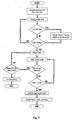
- Figure 8 outlines a possible logic path that will be followed by the electronic unit 16, according to a possible embodiment of the present invention.
- the first way is to check if the sensor data makes sense and that the sensors 18 (and the electronic unit 16) are functioning correctly, and the second way is to identify patterns in the data that suggest the rider may be experiencing a crash situation. This may either be through an impact with an obstacle, or from losing control of the motorcycle.
- the electronic unit 16 When a danger situation (for example a crash situation) has been identified, the electronic unit 16 will send a triggering signal to the emergency device so that the garment reacts to the danger situation.
- the triggering signal is sent to the gas generator 26 and this will cause a rapid injection of gas into the inflatable chamber of the airbag 28 causing it to inflate and infer additional impact protection to the rider.
- the inflatable chamber Once inflated, the inflatable chamber move from a rest condition, wherein it is in a deflated status, to an operating condition, wherein it is in an inflated status.
- an emergency signal will be passed to the supervisor and communication unit 17 which indicates that the rider has crashed, and then the data from the sensors 18 will be transmitted to the supervisor and communication unit.
- the data are sent directly to the smartphone 17 in real time. This data transmission will continue until the garment 12 is removed (which can be detected by the zip sensor 181) or the battery of the electronic unit 16 becomes discharged.
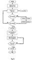
- Figure 7 details a possible embodiment according to the invention of the corresponding logic path that will be followed by the application running in the smartphone 17.
- the electronic unit 16 when the electronic unit 16 is powered on the smartphone 17 will see the Bluetooth signal, and provided the user had previously instructed the two devices to connect (known as 'pairing') a data connection will be established between the smartphone 17 and the electronic unit 16. This is established for the full period of time in which the garment 12 is worn.
- the unit In the event there is a fault situation the unit will communicate this to the smartphone 17. This will cause the smartphone 17 to vibrate and details of the fault will be available on its display, and according to a possible embodiment of the invention, simultaneously to the LED Display 44 of the garment.
- a further signal will be sent to the smartphone 17. This will cause it to start a timer, and switch to a different mode of operation whereby the sensor data stream is monitored by the smartphone 17 itself.
- the smartphone 17 will analyse the sensor data to check for variations in the readouts.
- a suitable threshold can be used to filter between these outside effects and the actual movements of the rider. If the variations in the sensor readouts do not pass above these thresholds the smartphone 17 will consult the timer that it started and if this is greater than a first prefixed time period, for example 45 seconds, it will engage the procedure to transmit the emergency message using the means, and information content that had been previously prescribed by the rider.
- the smartphone 17 sends more than one message to more than one different recipient.
- the smartphone 17 will operate its vibration motor and play a loud noise in order to catch the attention of the rider or any other person that may be in the vicinity, but who were unaware of the accident.
- the timer will be reset, but if the first prefixed time period is elapsed since the crash has been identified and no further assistance has been initially called, for a second prefixed time period, for example 30 minutes, the electronic unit 16 will continue the surveillance cycle to check that the movements do not cease for an unexpected reason. After 30 minutes the smartphone 17 will end the monitoring cycle.
- the above invention overcomes the drawbacks of the existing prior art by being able to monitor the condition of the rider after they have been involved in an accident and to intelligently decide, without any input from the rider, whether to request further assistance or not.
- the crash detected may be either an accident involving an impact with an obstacle, an accident where the riders lost control of the bike by themselves (a single vehicle accident as mentioned earlier) or may also be used in a non motorcycling context to identify other accident scenarios such as tripping over or a fall from height.
- the smartphone of the rider will be kept in a pocket close to the body. This may be a pocket in the airbag garment, or a pocket in a layer of underclothing or trousers that the user is wearing.
- the smartphone application can activate the vibration motor in the smartphone to provide an additional haptic warning of the fault. This is particularly useful because during riding the rider will be looking at the road ahead, and may not notice any warnings illuminated on the LED Display for some considerable time. With the haptic warning the rider can be alerted that they require to consult the LED Display or smartphone application to understand the new status of the electronic unit.
- the main benefit achieved through the smartphone link is the access to the GSM cellular network, which in the event of an accident permits a communication to be made to an outside party.
- This communication may be made by telephone, by the sending of an SMS Message, or the sending of e-mails or other data over the network if data transmission is available.
- the recipients of this information may be a relation of the user, or a central agency which co-ordinates a response to provide assistance. It should be noted that the message may contain personal details of the user that they have previously stored in the phone (such as name, address, age, blood group, allergies, etc%) but additionally can contain location information taken from the GPS Receiver.
- system of the present invention can:
- the user activity is monitored by means of the sensors and the level of user activity is assessed in order to decide or not to call for further assistance.
- this is obtained by continuing to utilise the data from the same sensors that were used to detect the crash.
- the sensors are mainly MEMs tri axis accelerometers, such as those manufactured by Analog Devices, however other sensors, such as GPS, gyroscopes, etc.. may be utilised.
- the electronic unit sends, concurrently with the triggering signal to the inflator device, the crash/emergency signal to the smartphone, it then starts to share not just the diagnostic data of the system, but also the data from the sensors that are on the garment of the user.
- the smartphone application will start to monitor the variations in these sensors and at the same time commence a countdown timer.
- the system can be set to decide for calling for further assistance when said monitored signals correspond to a level of user activity lower then a prefixed value and not necessarily to a complete lack of movement. In fact, for example, minimal movements can exist also when the user becomes unconscious.
- the supervisor unit in this case the smartphone application may try to 'wake' the user either haptically (by running the vibration motor in the smartphone), or aurally (by playing an irritable noise at the highest volume on the loudspeaker of the device).
- the zip sensor (outlined in said Italian patent application) would detect that the garment had been opened and in turn power off the electronic unit. This would prevent false alarms whereby the unworn garment lying on the ground could be mistaken for an unconscious user.
- the present invention refers to a garment comprising an emergency device, which contains sensing means and an electronic processing unit, intended to identify a danger situation for the user and react, whereby the electronic processing unit contains radio transmission & reception means to permit it to exchange data with a smartphone device present on the body of the user, characterised in that the smartphone, after being informed of the danger situation, monitors the user by means of the sensors in the garment, and autonomously assesses the level of user activity in order to decide or not to call for further assistance.
- an emergency device which contains sensing means and an electronic processing unit, intended to identify a danger situation for the user and react
- the electronic processing unit contains radio transmission & reception means to permit it to exchange data with a smartphone device present on the body of the user, characterised in that the smartphone, after being informed of the danger situation, monitors the user by means of the sensors in the garment, and autonomously assesses the level of user activity in order to decide or not to call for further assistance.
- the garment as outlined above is adapted to be of use in motorcycling activities.
- the system of the present invention is adapted to provide haptic warnings to the user in the event of a system malfunction.
- the garment as outlined above can provide precise details to the user of the system malfunction using the screen of a smartphone to illustrate and explain the problem.
- the system as outlined above is adapted to provide an emergency call by using either telephony, SMS Messages, an e-mail or equivalent data transmission over the internet.
- ency call is intended a communication using either telephony, SMS Messages, an e-mail or equivalent data transmission over the internet.
Description
- The present invention relates to a garment with an emergency device and to an associated emergency procedure. In particular the present invention refers to an emergency device and method suitable for being used in a motorcyclist garment.
- From a review of motorcycle accident statistics it is generally known that when another vehicle is involved, the accident has often occurred inside or close to an urban area. This often means that medical facilities are close by, and there are many people at an accident scene available to assist or call for help.
- However, when looking at single vehicle accidents (about 1/3 of the total) it is noted that the majority of accidents happen in the countryside, sometimes in particularly remote areas. In these circumstances, if an accident happens and the rider is left unconscious, many hours may pass before the rider is discovered and appropriate help is provided, which may be too late to prevent serious permanent injuries or death.
- The logical solution to this is for the rider to carry some kind of emergency locator beacon such as the one outlined in patent application
US2012075872 . However these have the distinct disadvantage in that they must be manually activated, which by definition means that the rider must be conscious and physically able to reach for and activate the unit. - In fact in many cases the cellular phone of the motorcyclist would be able to conduct the same function with the same level of interaction of the rider, so the notable expense of the beacon does not seem to be justified.
- Expanding on this idea, it could be evaluated that if the emergency beacon was able to know when the rider has been involved in a crash, it could automatically activate and request help.
- The recent availability of systems able to recognise a crash by a rider, such as that have been developed for the electronic airbag systems, has opened up this possibility, but this idea is not perfect because in the majority of cases the crash by the rider will not be serious, and thus a team of emergency services turning up to a minor incident would, apart from the waste of resources, create notable embarrassment to the rider such that they would be happier to remain with the manually activated beacon.
- The object of the invention is to provide a garment with an emergency device and an associated method of utilisation, which solve the above mentioned problems and drawbacks.
- Another object of the present invention, is to significantly overcome, and improve the prior art by providing a lower cost, more autonomous emergency call system that in the event of a crash only contacts emergency services in the particular cases where it is
KR 2012 0078760 A US 2009/254003 A1 andUS 2008/256687 A1 . - The invention is defined by a garment as claimed in claim 1 and a method as claimed in claim 10. Preferred embodiments are set out in the dependent claims.
- The advantages and the characteristic features of the invention will be appreciated more clearly from the following description of a preferred embodiment of the invention with reference to the accompanying figures in which:
-
Fig. 1 shows a schematic front view of a garment according to the invention; -
Fig. 2 shows a schematic rear view of a garment according to the invention; -
Fig. 3 shows a schematic view of an expansion board which contains a GPS and radio module; -
Fig. 4 shows a schematic view of the expansion board installed on a main circuit board of an electronic unit; -
Fig. 5 shows a schematic view of an outer jacket into which the garment may be installed; -
Fig. 6 shows a schematic view of an example of the information interface communicated to the user by the smartphone; -
Fig. 7 shows an example of flow chart executed in the smartphone unit to autonomously monitor the status of the user. -
Fig. 8 shows an example of flow chart of the base logic of the main electronic system; and -
Figure 1 shows a possible embodiments of agarment 12 according to the invention, in particular a vest style garment. It should be noted that although a vest-type garment is illustrated infigure 1 , the system of the present invention could also be utilised on other items of wearing apparel, such as a one piece bodysuit, trousers, gloves, boots or even protective helmet. - As clarified below, the
garment 12 is intended to identify a danger situation for the user and react. - Advantageously, the garment comprises an
emergency device 13 which is provided with at least oneinflatable chamber 28, aninflator device 26,sensors 18, anelectronic processing unit 16 and a supervisor andcommunication unit 17. - The supervisor and
communication unit 17, after being informed of the danger situation through an emergency signal received by the electronic processing unit, monitors the user by means of the sensors and assesses the level of user activity in order to decide or not to call for further assistance. According to the invention, the supervisor andcommunication unit 17 comprises asmartphone 17. - For example, on the inside of the vest a
pocket 14 can be provided on the chest.Such pocket 14 has been sized to comfortably accommodate asmartphone 17. - According to a possible embodiment of the invention, although the
pocket 14 is visible in the figure, when the closed garment is viewed, as illustrated infigure 1 , thesmartphone 17 would in reality not be visible without opening the garment first. Thepocket 14 has been advantageously provided on the inner layer of thegarment 12 for at least two reasons: - for protecting the smartphone in case of impact, and
- for sitting as close as possible the
smartphone 17 to the body of the user in order for the latter to be able to perceive the haptic alerts. - In other embodiments of the invention the
pocket 14 may be in a different position on or external to the body (such as in an item of luggage), and/or the pocket itself may be additionally padded or armoured to prevent damage to the phone during an accident. - By "smartphone" it is meant a phone with a versatile operating system and additional radio receivers (Bluetooth and/or Wifi) which permits the phone to interact with other devices and process information not directly connected with telephony; however a basic cellular phone with an additional radio receiver would also be adequate, as clarified below.
- In the introduction it was already mentioned that the first part of an autonomous emergency call system requires the system to know when the rider has crashed. The Italian patent application
TV2012A000124 - At the same time, the
emergency device 13 of the garment can be provided with an on-off switch suitable for disabling the airbag, namely the inflatable chambers, and the gas generator, without interfering with the operation of theelectronic processing unit 16 and the supervisor andcommunication unit 17. In this way, the garment might offer a proper protection to the user, even when the latter is not on a motorcycle. As a matter of fact, for example, it would be possible to make an emergency call without the needing to also inflate the inflatable chambers. - In the above mentioned Italian patent application the electronic unit is provided with an expansion slot in which additional electronic assemblies may be inserted to extend the functionality of the system. In said patent one example provided is the inclusion of an RFID reader in order to identify that the inflatable inner garment was only used with a compatible outer garment.
- For the purposes of this invention a new electronic assembly would be installed which contains a radio device (such as a class 2 Bluetooth receiver/transmitter or other network and transmission protocol) and/or a Global Positioning System (GPS) or equivalent navigation system reception antenna. Additional memory may also be provided such that the route taken by the rider and recorded by the GPS may be stored and downloaded by the rider to compile a logbook of their travels.
-
Figure 2 illustrates the rear of thegarment 12 offigure 1 . In this embodiment part of the rear pocket which covers theinflatable chamber 28 is covered in the centre with aback protector 24. Theback protector 24 itself is used as a mounting platform to secure theelectronic unit 16 and the gas generator orinflator device 26 which is used to fill an inflatable chamber of anairbag 28 with gas when the gas generator is triggered by the electronic processing unit in the event of an accident. - According to a possible embodiment of the present invention, two
sensors 18 can be positioned on the rear upper shoulders of thegarment 12, although the quantity and position of thesensors 18 could be any number, and anywhere on the body of the user and/or on the garment. -
Additional sensors 18 may be present on board theelectronic unit 16. Advantageouslyfurther sensors 18 may be provided, not connected to the detection of the accident, but connected to the monitoring of the rider after the crash (for example a heart rate monitor, or blood pressure sensor). - According to a possible embodiment of the present invention,
figure 4 shows an expansionelectronic PCB 22 which contains aGPS antenna 30 and a Bluetooth radio receiver andtransmitter 32. If the phone is not provided on theelectronic unit 16, it has to be situated within the rated operating range of a Bluetooth radio. - An example of the GPS unit is the UP501 system supplied by U-Blox SA, while an example of the Bluetooth chipset is the RN-03 supplied by Roving Networks Inc..
- Advantageously, the
smaller PCB 22 has twoconnectors 34 on the underside which permit it to be mated tocorresponding sockets 38 on the electronic unit 16 (seefigure 3 ). - This modularity of the system means that if a customer purchases the
electronic unit 16 without the expansionelectronic PCB 22 and then changes their mind in future, the expansionelectronic PCB 22 can be procured in isolation and installed at a later date to provide this additional functionality. Note that in this embodiment only aBluetooth radio 32 is present on the expansion board, however, as an example, it could also be possible that the GSM antenna is installed directly on the expansionelectronic PCB 22. In this case the processing and decision making to monitor the rider would be carried out completely on board theelectronic unit 16 without the requirement for the rider to own asmartphone 17. Furthermore theBluetooth radio 32 may still additionally be present as this makes it easier for the user to setup the parameters of the electronic unit using an external device (not shown). - In other words, supervisor and communication unit could be composed by an electronic part or
device 22 directly connected to the electronic unit 16 (advantageously thedevice 22 could be mounted on the electronic unit 16) and anexternal smartphone 17 near the device (advantageously in a pocket on the garment). Advantageously, theelectronic device 22 comprises a wireless communication interfaces adapted to be connected to thesmartphone 17. - According to the present invention, the supervisor part of the supervisor and
communication unit 17 is provided in the smartphone. Thesmartphone 17 is programmed for considering the data from the sensors and to decide or not to call for further assistance. For example the smartphone could be programmed as shown in flow chart offigure 7 . - According to a possible embodiment of the present invention, being the
garment 12 provided with anairbag 28, in normal use it is expected that thegarment 12 is worn with a compatibleouter garment 42. - In
figure 5 , it is illustrated a possible connection between the compatibleouter garment 42 between azip switch sensor 181 and an arm mountedLED Display 44. TheLED Display 44 can be positioned such that it is outside the garment and the indications of the LEDs can be viewed by the rider easily while riding. - According to a possible embodiment of the present invention, the
zip switch sensor 181 has acorresponding magnet 182 on the other side of the zip such that if the garment front zip is opened, the distance between thesensor 181 and themagnet 182 will increase, causing thesensor 181 to no longer 'see' themagnet 182 and this in turn would cause theelectronic unit 16 to power off. - As mentioned earlier, the
LED Display 44 can illuminate differing combinations of LEDs in order to communicate different operating states of theelectronic unit 16. However with the expansionelectronic PCB 22 installed the Bluetooth radio receiver andtransmitter 32 permits theelectronic unit 16 to be paired with thesmartphone 17 of the rider. This permits the two devices to exchange information. - According to a possible embodiment of the present invention, with an application specially coded to use this information and running on the
smartphone 17, the rider can obtain much more detailed information on the system which is presented in a way that is much easier to understand.Figure 6 provides an example of how this information may be presented to the user. In this example theexact battery condition 50 is provided, it is clearly stated that there are nofaults 52 with the system, andoptions 54 are provided on how to instruct thesmartphone 17 to handle the emergency situation. - In order to achieve the successful monitoring of the user, there must be a certain decision making path which is followed by the
electronic unit 16 and by thesmartphone 17 alike. -
Figure 8 outlines a possible logic path that will be followed by theelectronic unit 16, according to a possible embodiment of the present invention. - Once the
electronic unit 16 has been switched on there is an internal check that the system is working correctly. Once this has been completed data from thesensors 18 will be read and processed in two ways. The first way is to check if the sensor data makes sense and that the sensors 18 (and the electronic unit 16) are functioning correctly, and the second way is to identify patterns in the data that suggest the rider may be experiencing a crash situation. This may either be through an impact with an obstacle, or from losing control of the motorcycle. - When a danger situation (for example a crash situation) has been identified, the
electronic unit 16 will send a triggering signal to the emergency device so that the garment reacts to the danger situation. The triggering signal is sent to thegas generator 26 and this will cause a rapid injection of gas into the inflatable chamber of theairbag 28 causing it to inflate and infer additional impact protection to the rider. Once inflated, the inflatable chamber move from a rest condition, wherein it is in a deflated status, to an operating condition, wherein it is in an inflated status. At the same time an emergency signal will be passed to the supervisor andcommunication unit 17 which indicates that the rider has crashed, and then the data from thesensors 18 will be transmitted to the supervisor and communication unit. The data are sent directly to thesmartphone 17 in real time. This data transmission will continue until thegarment 12 is removed (which can be detected by the zip sensor 181) or the battery of theelectronic unit 16 becomes discharged. -
Figure 7 details a possible embodiment according to the invention of the corresponding logic path that will be followed by the application running in thesmartphone 17. In this case when theelectronic unit 16 is powered on thesmartphone 17 will see the Bluetooth signal, and provided the user had previously instructed the two devices to connect (known as 'pairing') a data connection will be established between thesmartphone 17 and theelectronic unit 16. This is established for the full period of time in which thegarment 12 is worn. In the event there is a fault situation the unit will communicate this to thesmartphone 17. This will cause thesmartphone 17 to vibrate and details of the fault will be available on its display, and according to a possible embodiment of the invention, simultaneously to theLED Display 44 of the garment. - In the event where the rider has crashed a further signal will be sent to the
smartphone 17. This will cause it to start a timer, and switch to a different mode of operation whereby the sensor data stream is monitored by thesmartphone 17 itself. Thesmartphone 17 will analyse the sensor data to check for variations in the readouts. - According to a possible embodiment of the invention, given that outside effects (such as a strong wind blowing over the rider) could also produce some small oscillations, a suitable threshold can be used to filter between these outside effects and the actual movements of the rider. If the variations in the sensor readouts do not pass above these thresholds the
smartphone 17 will consult the timer that it started and if this is greater than a first prefixed time period, for example 45 seconds, it will engage the procedure to transmit the emergency message using the means, and information content that had been previously prescribed by the rider. - Advantageously, it is entirely possible that the
smartphone 17 sends more than one message to more than one different recipient. - According to a possible embodiment of the present invention, at the same time the
smartphone 17 will operate its vibration motor and play a loud noise in order to catch the attention of the rider or any other person that may be in the vicinity, but who were unaware of the accident. - According to a further possible feature of the present invention, if on the other hand variations are seen in the data which confirm the rider is conscious, the timer will be reset, but if the first prefixed time period is elapsed since the crash has been identified and no further assistance has been initially called, for a second prefixed time period, for example 30 minutes, the
electronic unit 16 will continue the surveillance cycle to check that the movements do not cease for an unexpected reason. After 30 minutes thesmartphone 17 will end the monitoring cycle. - In conclusion the above invention overcomes the drawbacks of the existing prior art by being able to monitor the condition of the rider after they have been involved in an accident and to intelligently decide, without any input from the rider, whether to request further assistance or not.
- The crash detected may be either an accident involving an impact with an obstacle, an accident where the riders lost control of the bike by themselves (a single vehicle accident as mentioned earlier) or may also be used in a non motorcycling context to identify other accident scenarios such as tripping over or a fall from height.
- With the installation of a suitable application on the smartphone, information can be exchanged between the smartphone and the electronic unit. Obviously the most important information is the signal that the rider has had an accident, but much more information may be shared to assist the rider, which will now be discussed.
- In most cases the smartphone of the rider will be kept in a pocket close to the body. This may be a pocket in the airbag garment, or a pocket in a layer of underclothing or trousers that the user is wearing. In these situations, and in the event there is a fault or malfunction with the electronic system (or the associated airbag components), the smartphone application can activate the vibration motor in the smartphone to provide an additional haptic warning of the fault. This is particularly useful because during riding the rider will be looking at the road ahead, and may not notice any warnings illuminated on the LED Display for some considerable time. With the haptic warning the rider can be alerted that they require to consult the LED Display or smartphone application to understand the new status of the electronic unit.
- In the context of this invention thought, the main benefit achieved through the smartphone link is the access to the GSM cellular network, which in the event of an accident permits a communication to be made to an outside party. This communication may be made by telephone, by the sending of an SMS Message, or the sending of e-mails or other data over the network if data transmission is available.
- The recipients of this information may be a relation of the user, or a central agency which co-ordinates a response to provide assistance. It should be noted that the message may contain personal details of the user that they have previously stored in the phone (such as name, address, age, blood group, allergies, etc...) but additionally can contain location information taken from the GPS Receiver.
- In the first case this would be taken from GPS antenna on the electronic assembly, as the physically larger antenna permits a more accurate signal, however if for some reason no location could be reckoned from that device, the smartphone application could then request the location to be taken from the built in GPS antenna which is very commonly integrated in today's smartphones.
- Therefore, it can now be appreciated that system of the present invention can:
- Identify a crash situation
- Be connected wirelessly to a smartphone
- Make a communication on the GSM network to request assistance which includes the location of the incident.
- Moreover, the user activity is monitored by means of the sensors and the level of user activity is assessed in order to decide or not to call for further assistance.
- Advantageously, this is obtained by continuing to utilise the data from the same sensors that were used to detect the crash.
- In the current state of art almost all airbag systems (car and motorcycle) function through sensors that are mounted on the chassis or forks of the vehicle, however in the said Italian patent application it can be seen that the sensors used to detect a crash have been integrated into the garment. In this embodiment the sensors are mainly MEMs tri axis accelerometers, such as those manufactured by Analog Devices, however other sensors, such as GPS, gyroscopes, etc.. may be utilised.
- Subsequently this permits the behaviour of the user to be monitored, even after the crash. Thus when the electronic unit sends, concurrently with the triggering signal to the inflator device, the crash/emergency signal to the smartphone, it then starts to share not just the diagnostic data of the system, but also the data from the sensors that are on the garment of the user. At this point the smartphone application will start to monitor the variations in these sensors and at the same time commence a countdown timer.
- It can easily be understood that if the rider becomes unconscious during the accident he will be incapable of making any body movements and thus once the accident has completed its course they user will be completely still. This lack of movement will be seen by the sensors and monitored by the smartphone, and will be compared to the countdown timer. If after 45 seconds (or other prefixed time period which may be specified by the user) there is no change in the sensor output (indication that the rider has not moved) the application on the smartphone will send the emergency messages on the GSM network.
- Obviously, the system can be set to decide for calling for further assistance when said monitored signals correspond to a level of user activity lower then a prefixed value and not necessarily to a complete lack of movement. In fact, for example, minimal movements can exist also when the user becomes unconscious.
- At the same time (or during the monitoring period) the supervisor unit (in this case the smartphone application) may try to 'wake' the user either haptically (by running the vibration motor in the smartphone), or aurally (by playing an irritable noise at the highest volume on the loudspeaker of the device).
- On the other hand, should the accident be less serious, it is obvious that once the accident has completed its course the rider will start to move in some way. These movements will be perceived by the sensors and transmitted to the smartphone, which will then reset the first countdown timer and will not send any emergency message. However given that in some circumstances the rider may not lose consciousness immediately, the user shall continue to be monitored for the next 30 minutes (or other preset time period), and if at any time in that period there are 45 seconds of non-movement (or under-threshold movements) recorded, an emergency communication will be made.
- It may also happen that the user chooses to remove the garment during this monitoring period. In this case the zip sensor (outlined in said Italian patent application) would detect that the garment had been opened and in turn power off the electronic unit. This would prevent false alarms whereby the unworn garment lying on the ground could be mistaken for an unconscious user.
- Therefore, the present invention refers to a garment comprising an emergency device, which contains sensing means and an electronic processing unit, intended to identify a danger situation for the user and react, whereby the electronic processing unit contains radio transmission & reception means to permit it to exchange data with a smartphone device present on the body of the user, characterised in that the smartphone, after being informed of the danger situation, monitors the user by means of the sensors in the garment, and autonomously assesses the level of user activity in order to decide or not to call for further assistance.
- In particular, the garment as outlined above is adapted to be of use in motorcycling activities.
- The system of the present invention is adapted to provide haptic warnings to the user in the event of a system malfunction.
- Advantageously the garment as outlined above, can provide precise details to the user of the system malfunction using the screen of a smartphone to illustrate and explain the problem.
- The system as outlined above, is adapted to provide an emergency call by using either telephony, SMS Messages, an e-mail or equivalent data transmission over the internet.
- At this point it is clear how the predefined objects have been achieved.
- Obviously, the above description of an embodiment applying the innovative principles of the present invention is provided by way of example of these innovative principles and must therefore not be regarded as limiting the scope of the rights claimed herein.
- For example with "emergency call" is intended a communication using either telephony, SMS Messages, an e-mail or equivalent data transmission over the internet.
Claims (17)
- Garment (12), intended to identify a danger situation for the user and react, comprising an emergency device (13), said emergency device (13) comprising:- at least one inflatable chamber (28), suitable for moving between a rest condition, wherein it is in a deflated status, and an operating condition, wherein it is in an inflated status;- an inflator device (26) coupled to the at least one inflatable chamber (28) and designed for inflating the at least one inflatable chamber (28), once the inflator device (26) is triggered;- sensors (18), suitable for detecting data concerning the acceleration undergone by the garment (12) and movements of the user of the garment (12);- an electronic processing unit (16) designed for processing the acceleration data detected by the sensors (18) and, when a danger situation is identified, for sending a triggering signal to the inflator device (26) so as to inflate the at least one inflatable chamber (28); and- a supervisor and communication unit comprising a smartphone (17) suitable for being connected to the electronic processing unit (16);characterized in that,
when a danger situation is identified, the electronic processing unit (16) concurrently with the triggering signal to the inflator device (26), is adapted to send an emergency signal to the smartphone (17) that, after being informed of the danger situation through the emergency signal received from the electronic processing unit (16), is adapted to start to monitor the user by processing the data detected by the sensors (18) for assessing the level of user activity in order to decide or not to call for further assistance. - Garment (12) according to claim 1, characterized in that the smartphone (17) is designed to monitor, for a first prefixed time period after the danger situation has been identified by the electronic processing unit (16), the data detected by the sensors (18) to decide for calling for further assistance when said detected data correspond to a level of user activity lower than a prefixed value.
- Garment (12) according to claim 2, characterized in that the smartphone (17) is designed to monitor for a second prefixed time period, after the first prefixed time period is elapsed and no further assistance has been initially called, the data detected by the sensors (18) to decide for subsequently calling for further assistance when said detected data correspond to a level of user activity lower than a prefixed value.
- Garment (12) according to claim 1, characterized in that the supervisor and communication unit is composed by an expansion electronic board (22), comprising a navigation system reception antenna (30) and a receiver and transmitter radio device (32), and the smartphone (17).
- Garment (12) according to claim 4, characterized in that the receiver and transmitter radio device (32) comprises a wireless communication interfaces adapted to be connected to the smartphone (17).
- Garment (12) according to claim 5, characterized in that said wireless communication interfaces is a Bluetooth radio receiver and transmitter (32) for receiving from and transmitting data to the smartphone (17), the smartphone (17) being situated within the operating range of the Bluetooth radio receiver and transmitter (32).
- Garment (12) according to claim 4, characterized in that the navigation system reception antenna comprises a GPS device (30).
- Garment (12) according to claim 4, characterized in that the expansion electronic board (22) is directly connected or mounted on the electronic processing unit (16).
- Garment (12) according to claim 1, characterized in that it comprises a pocket (14) sized for accommodating the smartphone (17).
- Method for identifying a danger situation and for emitting an automatic radio emergency call, comprising the following steps:- providing a garment (12) comprising:- at least one inflatable chamber (28), suitable for moving between a rest condition, wherein it is in a deflated status, and an operating condition, wherein it is in an inflated status;- an inflator device (26) coupled to the at least one inflatable chamber (28) and designed for inflating the at least one inflatable chamber (28);- sensors (18);- an electronic processing unit (16); and- a supervisor and communication unit comprising a smartphone (17) suitable for being connected with the electronic processing unit (16);- connecting the electronic processing unit (16) and the smartphone (17);- the electronic processing unit (16) identifying a danger situation for the user of the garment (12) by processing the data detected by the sensors (18);- when a danger situation has been identified, the electronic processing unit (16) sending a triggering signal to the inflator device (26), for inflating the at least one inflatable chamber (28), and passing to the smartphone (17) an emergency signal so that the data detected by the sensors (18) are transmitted to the smartphone (17);- the smartphone (17) monitoring for a first prefixed time period, after the danger situation has been identified, the user of the garment (12) by means of the sensors (18) for assessing the level of user activity; and- the smartphone (17) deciding or not to call for further assistance depending on the level of the assessed user's activity.
- Method according to claim 10, in which the level of user's activity for deciding automatically to call for further assistance corresponding to a level of user's activity lower than a prefixed value.
- Method according to claim 10, characterized in that it further comprises the step of monitoring for a second prefixed time period, after the first prefixed time period is elapsed and no further assistance has been initially called, the user of the garment (12) by means of the sensors (18) for assessing the level of user's activity.
- Method according to claim 10, characterized in that it further comprises the step of providing, when a danger situation has been detected or the level of user's activity is lower than a prefixed value, an haptic alert to user.
- Method according to claim 10, characterized in that it further comprises the step of providing, when a danger situation has been detected or the level of user's activity is lower than a prefixed value, an haptic alert and/or an audible alert to user.
- Method according to claim 12, characterized in that it further comprises the step of ending the monitoring step when the second prefixed time period is elapsed without the needing to call for further assistance.
- Method according to claim 10, characterized in that it further comprises the step of storing in the garment (12) personal details of the user; said details being suitable for being sent outside the garment (12) concurrently with the call for further assistance when a danger situation has been detected.
- Method according to claim 10, characterized in that the smartphone (17) is connected wirelessly to the electronic processing unit (16).
Priority Applications (1)
| Application Number | Priority Date | Filing Date | Title |
|---|---|---|---|
| EP18166464.0A EP3364390B1 (en) | 2013-08-06 | 2014-08-01 | Garment with an emergency device and associated emergency method |
Applications Claiming Priority (2)
| Application Number | Priority Date | Filing Date | Title |
|---|---|---|---|
| IT000130A ITTV20130130A1 (en) | 2013-08-06 | 2013-08-06 | CLOTHING WITH AN EMERGENCY DEVICE AND ASSOCIATED EMERGENCY METHOD |
| PCT/IB2014/063625 WO2015019261A1 (en) | 2013-08-06 | 2014-08-01 | Garment with an emergency device and associated emergency method |
Related Child Applications (2)
| Application Number | Title | Priority Date | Filing Date |
|---|---|---|---|
| EP18166464.0A Division-Into EP3364390B1 (en) | 2013-08-06 | 2014-08-01 | Garment with an emergency device and associated emergency method |
| EP18166464.0A Division EP3364390B1 (en) | 2013-08-06 | 2014-08-01 | Garment with an emergency device and associated emergency method |
Publications (2)
| Publication Number | Publication Date |
|---|---|
| EP3031040A1 EP3031040A1 (en) | 2016-06-15 |
| EP3031040B1 true EP3031040B1 (en) | 2018-05-30 |
Family
ID=49354857
Family Applications (2)
| Application Number | Title | Priority Date | Filing Date |
|---|---|---|---|
| EP18166464.0A Active EP3364390B1 (en) | 2013-08-06 | 2014-08-01 | Garment with an emergency device and associated emergency method |
| EP14771391.1A Active EP3031040B1 (en) | 2013-08-06 | 2014-08-01 | Garment with an emergency device and associated emergency method |
Family Applications Before (1)
| Application Number | Title | Priority Date | Filing Date |
|---|---|---|---|
| EP18166464.0A Active EP3364390B1 (en) | 2013-08-06 | 2014-08-01 | Garment with an emergency device and associated emergency method |
Country Status (11)
| Country | Link |
|---|---|
| US (1) | US11540566B2 (en) |
| EP (2) | EP3364390B1 (en) |
| JP (2) | JP6538686B2 (en) |
| KR (1) | KR102240534B1 (en) |
| CN (1) | CN105431890B (en) |
| AU (1) | AU2014304154B2 (en) |
| BR (1) | BR112016002536B1 (en) |
| ES (2) | ES2685618T3 (en) |
| IT (1) | ITTV20130130A1 (en) |
| RU (1) | RU2647686C2 (en) |
| WO (1) | WO2015019261A1 (en) |
Families Citing this family (32)
| Publication number | Priority date | Publication date | Assignee | Title |
|---|---|---|---|---|
| US10104178B2 (en) * | 2014-05-27 | 2018-10-16 | Genesys Telecommunications Laboratories, Inc. | System for managing communications activated by a trigger event |
| US10300975B2 (en) * | 2014-07-22 | 2019-05-28 | Alpinestars Research Srl | Protective garment provided with an inflatable protective device and associated inflating method |
| US20160029717A1 (en) * | 2014-07-30 | 2016-02-04 | Neil A. DiMarco | Running Shirt with Quick Release Sleeves |
| JP2016062637A (en) | 2014-09-12 | 2016-04-25 | パナソニック インテレクチュアル プロパティ コーポレーション オブ アメリカPanasonic Intellectual Property Corporation of America | Recording medium, reproduction apparatus and reproducing method |
| FR3031881B1 (en) * | 2015-01-28 | 2017-01-27 | In&Motion | REMOVABLE ELECTRONIC SYSTEM FOR RELEASING THE DEPLOYMENT OF AN INFLATABLE SAFETY VEST |
| US10849369B2 (en) | 2015-05-29 | 2020-12-01 | Nike, Inc. | Apparel with wireless-powered sensors |
| WO2016207920A1 (en) * | 2015-06-23 | 2016-12-29 | Lin Up Srl | Device for acquisition and processing of data concerning human activity at workplace |
| IT201600077880A1 (en) * | 2016-07-25 | 2018-01-25 | Easyfly Sagl | EMERGENCY CALL SIGNALING AND MANAGEMENT SYSTEM FOR PERFORMED MOPEDS |
| WO2017085703A1 (en) * | 2015-11-20 | 2017-05-26 | Easyfly Sagl | System for the signaling and management of emergency calls for motorcycles |
| US10154695B2 (en) * | 2015-12-28 | 2018-12-18 | Xin Jin | Personal wearable airbag device for preventing injury |
| US11000078B2 (en) * | 2015-12-28 | 2021-05-11 | Xin Jin | Personal airbag device for preventing bodily injury |
| US10897938B2 (en) | 2016-01-27 | 2021-01-26 | Davenport Saf-T Systems LLC | Wearable device for fall injury mitigation |
| ITUB20160849A1 (en) * | 2016-02-18 | 2017-08-18 | Dainese Spa | PROTECTION DEVICE AND ITS FUNCTIONING METHOD |
| IT201600068775A1 (en) * | 2016-07-01 | 2018-01-01 | Alpinestars Res Srl | Garment provided with an inflatable protective device |
| US10318005B2 (en) * | 2016-08-09 | 2019-06-11 | Google Llc | Haptic feedback mechanism for an interactive garment |
| KR101924904B1 (en) | 2016-12-26 | 2018-12-05 | 전성훈 | Safety suit for a motorcycle |
| ES2648542A1 (en) * | 2017-03-31 | 2018-01-03 | Centro Tecnológico Del Mueble Y La Madera De La Región De Murcia | System for the detection and notification of motorcycle accidents (Machine-translation by Google Translate, not legally binding) |
| WO2019035509A1 (en) * | 2017-08-18 | 2019-02-21 | 세이프웨어(주) | Safety device having inflator |
| JP7033207B2 (en) * | 2017-10-09 | 2022-03-09 | 北京▲孫▼寅▲貴▼▲緑▼色科技研究院有限公司 | Rapid inflator / air bleeding device for protective clothing and smart multipurpose protective clothing equipped with the device |
| DE102017223515A1 (en) * | 2017-12-21 | 2019-06-27 | Robert Bosch Gmbh | Device and method for monitoring a person |
| IT201800002348A1 (en) * | 2018-02-02 | 2019-08-02 | Alpinestars Res Srl | Garment prepared with an inflatable protective device and related method for adjusting the operating modes of the inflatable protective device |
| RU186691U1 (en) * | 2018-07-23 | 2019-01-29 | Владимир Васильевич Харитонов | DEVICE FOR TESTING VIRTUAL VEST |
| SE543986C2 (en) * | 2019-01-17 | 2021-10-19 | Hoevding Sverige Ab | Airbag system comprising control unit arranged to control inflation of the airbag based on a measured magnetic field |
| KR20210145204A (en) * | 2019-03-29 | 2021-12-01 | 잉위 쑨 | Smart multi-purpose anti-collision clothing and ski slope safety system |
| CN110047290A (en) * | 2019-05-17 | 2019-07-23 | 西安工业大学 | Highway Maintenance and accident treatment safety pre-warning system |
| AU2020382601A1 (en) | 2019-11-14 | 2022-05-26 | Milwaukee Electric Tool Corporation | Hard hat attachment system and safety equipment |
| US11272455B2 (en) * | 2020-06-16 | 2022-03-08 | Hewlett Packard Enterprise Development Lp | Dynamic frequency selection for wake up radio |
| WO2022013591A1 (en) * | 2020-07-12 | 2022-01-20 | Gimoto S.R.L. | Electronic unit for a safety system actuation |
| CN112137191A (en) * | 2020-09-27 | 2020-12-29 | 西安邮电大学 | Work clothes for cleaning |
| RU2759481C1 (en) * | 2020-12-10 | 2021-11-15 | Федеральное государственное бюджетное образовательное учреждение высшего образования «Сибирский государственный автомобильно-дорожный университет (СибАДИ)» | Method for protecting the limbs of an employee from damage by moving parts of the mechanism |
| CN112450512A (en) * | 2020-12-25 | 2021-03-09 | 江南大学 | Female wolf-proof garment based on comprehensive positioning technology |
| FR3110817B1 (en) * | 2021-01-13 | 2024-01-12 | N2A | Inflatable protection and safety equipment for the user of a means of transport such as a motorcycle |
Citations (11)
| Publication number | Priority date | Publication date | Assignee | Title |
|---|---|---|---|---|
| GB2350263A (en) | 1999-03-24 | 2000-11-22 | Bernard Leighton | Providing an alert of an abnormal medical condition |
| US20010024949A1 (en) | 2000-03-14 | 2001-09-27 | Yazaki Corporation. | Jacket with multiband transmitter-receiver function and system using the same |
| US20020160723A1 (en) | 2001-04-27 | 2002-10-31 | Miguel Yagi | Helmet with incorporated communication system |
| US7181192B2 (en) | 2004-03-16 | 2007-02-20 | Texas Instruments Incorporated | Handheld portable automatic emergency alert system and method |
| EP1779772A1 (en) | 2004-06-21 | 2007-05-02 | Fundacion Fatronik | System for analysing a person's activity and for automatic fall detection |
| US20090254003A1 (en) | 2002-12-18 | 2009-10-08 | Buckman Robert F | Method and Apparatus for Body Impact Protection |
| DE102009033560A1 (en) | 2009-02-26 | 2010-09-09 | Technische Fachhochschule Wildau | Mobile device i.e. mobile radio device, controlling method for automatically outputting emergency message during accident of e.g. motorcycle, involves sending emergency message when emergency situation is detected by evaluating data |
| US20120188083A1 (en) | 2011-01-20 | 2012-07-26 | At&T Intellectual Property I, L.P. | Wireless monitoring of safety helmets |
| US8232881B2 (en) | 2007-03-07 | 2012-07-31 | Umbilical Design Ab | System for detecting an accident |
| WO2012104833A2 (en) | 2011-02-03 | 2012-08-09 | Hip Hope Technologies Ltd. | Hip protector system and method for hip fracture prevention |
| KR101207012B1 (en) | 2010-12-31 | 2012-11-30 | 서재언 | Safety vest |
Family Cites Families (45)
| Publication number | Priority date | Publication date | Assignee | Title |
|---|---|---|---|---|
| SU1509021A1 (en) | 1969-03-18 | 1989-09-23 | С.К.Мамаев | Apparatus for protecting the man from traumas when falling |
| JPH0695646B2 (en) | 1986-06-20 | 1994-11-24 | 鹿島建設株式会社 | Portable emergency reporting device |
| US6126194A (en) * | 1997-03-31 | 2000-10-03 | Simula, Inc. | Inflatable tubular torso restraint system |
| JP2000317002A (en) * | 1999-05-12 | 2000-11-21 | Japan Steel Works Ltd:The | Method and device for detecting and preventing fall of body |
| WO2002004251A1 (en) * | 2000-07-07 | 2002-01-17 | Intelligent Designs 2000 Corp. | Carrying case with selectively adjustable stand |
| US20020009335A1 (en) * | 2000-07-18 | 2002-01-24 | Courtney William L. | Vertically eccentric, horizontally symmetric, mobile and fixed buoyant in combination with mobile and fixed ballast as a type a personal flotation device |
| ES2243408T3 (en) * | 2000-08-25 | 2005-12-01 | Kyozo Kobayashi | COVER FOR SEAT BELT. |
| IT1317903B1 (en) * | 2000-09-06 | 2003-07-15 | Dainese Spa | HEAD OF CLOTHING STRUCTURED FOR THE PROTECTION OF THE MOTORCYCLIST. |
| US6801140B2 (en) * | 2001-01-02 | 2004-10-05 | Nokia Corporation | System and method for smart clothing and wearable electronic devices |
| US7304600B2 (en) * | 2004-12-16 | 2007-12-04 | Media Lab Europe (In Voluntary Liquidation) | Bluetooth remote controller using zipper interface |
| US20060143775A1 (en) * | 2005-01-06 | 2006-07-06 | Nam-Woo Kim | Multipurpose vest for leisure and sport |
| US20060212986A1 (en) * | 2005-03-23 | 2006-09-28 | Ivoice, Inc. | Pedestrian air bag device |
| US20060288464A1 (en) | 2005-06-24 | 2006-12-28 | Warden Matthew P | Personal protection device |
| CN1736515A (en) * | 2005-08-12 | 2006-02-22 | 魏景波 | Human body active protecting arrangement and application method thereof |
| GB2435979A (en) | 2006-03-07 | 2007-09-12 | Helen Theresa Haywood | Door intercom telephone device |
| JP2007257170A (en) * | 2006-03-22 | 2007-10-04 | Tanizawa Seisakusho Ltd | Alarm device |
| US7450014B2 (en) * | 2006-04-10 | 2008-11-11 | Houshang Farhadian | Open fastener indicator |
| US20070281732A1 (en) * | 2006-06-02 | 2007-12-06 | Peter Michael Fox | Method and system for securing a hands-free headset portion of a communication system |
| ITRM20060548A1 (en) | 2006-10-12 | 2008-04-13 | Dainese Spa | INFLATABLE DEVICE FOR PERSONAL PROTECTION AND GARMENT INCLUDING THE SAME |
| JP2008225761A (en) * | 2007-03-12 | 2008-09-25 | Eager Co Ltd | Accident notification device |
| US20080256687A1 (en) * | 2007-04-23 | 2008-10-23 | Spencer Brycen L | Helmet |
| US20090055053A1 (en) * | 2007-08-26 | 2009-02-26 | Yoram Carmeli | System and method for protecting a motorcycle rider |
| US20090195400A1 (en) * | 2007-10-25 | 2009-08-06 | Viktor Oreshkin | Zipper warning alarm system |
| JP2010262485A (en) * | 2009-05-07 | 2010-11-18 | Nec Access Technica Ltd | Jacket device and state detection method |
| US20120304367A1 (en) * | 2010-02-26 | 2012-12-06 | Thl Holding Company, Llc | Protective helmet |
| JP5378285B2 (en) * | 2010-03-30 | 2013-12-25 | 本田技研工業株式会社 | Airbag jacket actuator |
| US20130041272A1 (en) | 2010-04-20 | 2013-02-14 | Wearable Information Technologies, S.L. (Weartech) | Sensor apparatus adapted to be incorporated in a garment |
| US20120075872A1 (en) | 2010-06-24 | 2012-03-29 | Buddy Byrne | Emergency Response Locator Beacon |
| ES2377268B2 (en) * | 2010-07-13 | 2013-01-30 | Scio Soft, S.L. | PERSONAL SYSTEM AND EQUIPMENT OF PASSIVE SAFETY IN BOATS FOR WATER MAN SITUATIONS. |
| DE102010031976A1 (en) | 2010-07-22 | 2012-01-26 | Carl Zeiss Industrielle Messtechnik Gmbh | Determination of the coupling of parts to a machine |
| US20120190413A1 (en) * | 2010-12-03 | 2012-07-26 | Helen Ojeda | Cell phone belt pack |
| KR101016610B1 (en) | 2010-12-14 | 2011-02-24 | 이화여자대학교 산학협력단 | Aerial pressurizing smart-wear system for preparing against fall accident |
| KR101016611B1 (en) * | 2010-12-14 | 2011-02-24 | 이화여자대학교 산학협력단 | Aerial pressurizing smart-wear system for preparing against collision accident by mobile |
| CN102551685B (en) | 2010-12-30 | 2015-04-01 | 世意法(北京)半导体研发有限责任公司 | Object monitor |
| US8860570B2 (en) | 2011-02-03 | 2014-10-14 | SenseTech, LLC | Portable wireless personal head impact reporting system |
| US9489815B2 (en) * | 2011-04-29 | 2016-11-08 | Koninklijke Philips N.V. | Apparatus for use in a fall detector or fall detection system, and a method of operating the same |
| JP2013092923A (en) | 2011-10-26 | 2013-05-16 | Seiko Epson Corp | Fall detection device and fall monitoring system |
| ITTV20120124A1 (en) | 2012-06-26 | 2013-12-27 | Alpinestars Res Srl | INFLATABLE PROTECTION DEVICE MOUNTED ON THE LINING AND PROTECTIVE CLOTHING ASSEMBLY |
| CN202619644U (en) | 2012-07-12 | 2012-12-26 | 上海颂联国际服饰有限公司 | Clothes with function of detecting vital sign of human body |
| CN102867393B (en) * | 2012-09-18 | 2014-09-10 | 浙江吉利汽车研究院有限公司杭州分公司 | Automatic vehicle call-for-help method and system |
| US8662528B1 (en) * | 2013-07-29 | 2014-03-04 | Ali Gh. S. Gh. Abdulaziz | Protective suit |
| US20160183607A1 (en) * | 2014-02-11 | 2016-06-30 | Biosensor, LLC | Protective Clothing Article Including Fall Sensors and Deployable Air Bags |
| US10300975B2 (en) * | 2014-07-22 | 2019-05-28 | Alpinestars Research Srl | Protective garment provided with an inflatable protective device and associated inflating method |
| US9963210B1 (en) * | 2015-08-24 | 2018-05-08 | Julius-Peters N. Ebot | Wet suit with inflatable compartments and heating means |
| US20180330581A1 (en) * | 2017-05-10 | 2018-11-15 | Joelene Latief | Mobile communication device for deactivating a zipper alarm |
-
2013
- 2013-08-06 IT IT000130A patent/ITTV20130130A1/en unknown
-
2014
- 2014-08-01 RU RU2016107550A patent/RU2647686C2/en active
- 2014-08-01 WO PCT/IB2014/063625 patent/WO2015019261A1/en active Application Filing
- 2014-08-01 EP EP18166464.0A patent/EP3364390B1/en active Active
- 2014-08-01 KR KR1020167003403A patent/KR102240534B1/en active IP Right Grant
- 2014-08-01 ES ES14771391.1T patent/ES2685618T3/en active Active
- 2014-08-01 AU AU2014304154A patent/AU2014304154B2/en active Active
- 2014-08-01 ES ES18166464T patent/ES2953682T3/en active Active
- 2014-08-01 EP EP14771391.1A patent/EP3031040B1/en active Active
- 2014-08-01 BR BR112016002536-9A patent/BR112016002536B1/en active IP Right Grant
- 2014-08-01 JP JP2016532773A patent/JP6538686B2/en active Active
- 2014-08-01 CN CN201480043340.0A patent/CN105431890B/en active Active
- 2014-08-01 US US14/910,066 patent/US11540566B2/en active Active
-
2019
- 2019-04-03 JP JP2019071392A patent/JP6851414B2/en active Active
Patent Citations (11)
| Publication number | Priority date | Publication date | Assignee | Title |
|---|---|---|---|---|
| GB2350263A (en) | 1999-03-24 | 2000-11-22 | Bernard Leighton | Providing an alert of an abnormal medical condition |
| US20010024949A1 (en) | 2000-03-14 | 2001-09-27 | Yazaki Corporation. | Jacket with multiband transmitter-receiver function and system using the same |
| US20020160723A1 (en) | 2001-04-27 | 2002-10-31 | Miguel Yagi | Helmet with incorporated communication system |
| US20090254003A1 (en) | 2002-12-18 | 2009-10-08 | Buckman Robert F | Method and Apparatus for Body Impact Protection |
| US7181192B2 (en) | 2004-03-16 | 2007-02-20 | Texas Instruments Incorporated | Handheld portable automatic emergency alert system and method |
| EP1779772A1 (en) | 2004-06-21 | 2007-05-02 | Fundacion Fatronik | System for analysing a person's activity and for automatic fall detection |
| US8232881B2 (en) | 2007-03-07 | 2012-07-31 | Umbilical Design Ab | System for detecting an accident |
| DE102009033560A1 (en) | 2009-02-26 | 2010-09-09 | Technische Fachhochschule Wildau | Mobile device i.e. mobile radio device, controlling method for automatically outputting emergency message during accident of e.g. motorcycle, involves sending emergency message when emergency situation is detected by evaluating data |
| KR101207012B1 (en) | 2010-12-31 | 2012-11-30 | 서재언 | Safety vest |
| US20120188083A1 (en) | 2011-01-20 | 2012-07-26 | At&T Intellectual Property I, L.P. | Wireless monitoring of safety helmets |
| WO2012104833A2 (en) | 2011-02-03 | 2012-08-09 | Hip Hope Technologies Ltd. | Hip protector system and method for hip fracture prevention |
Also Published As
| Publication number | Publication date |
|---|---|
| EP3031040A1 (en) | 2016-06-15 |
| RU2016107550A (en) | 2017-09-12 |
| BR112016002536B1 (en) | 2022-06-21 |
| JP6851414B2 (en) | 2021-03-31 |
| WO2015019261A1 (en) | 2015-02-12 |
| US20160174626A1 (en) | 2016-06-23 |
| ES2685618T3 (en) | 2018-10-10 |
| RU2647686C2 (en) | 2018-03-16 |
| CN105431890A (en) | 2016-03-23 |
| ES2953682T3 (en) | 2023-11-15 |
| JP6538686B2 (en) | 2019-07-03 |
| EP3364390B1 (en) | 2023-06-07 |
| AU2014304154B2 (en) | 2019-01-24 |
| KR102240534B1 (en) | 2021-04-15 |
| ITTV20130130A1 (en) | 2015-02-07 |
| AU2014304154A1 (en) | 2016-02-25 |
| JP2019164799A (en) | 2019-09-26 |
| CN105431890B (en) | 2018-04-13 |
| JP2016534442A (en) | 2016-11-04 |
| BR112016002536A2 (en) | 2017-08-01 |
| KR20160040208A (en) | 2016-04-12 |
| EP3364390A1 (en) | 2018-08-22 |
| US11540566B2 (en) | 2023-01-03 |
Similar Documents
| Publication | Publication Date | Title |
|---|---|---|
| EP3031040B1 (en) | Garment with an emergency device and associated emergency method | |
| US20080256687A1 (en) | Helmet | |
| US9769638B2 (en) | Safety helmet and vehicle system, circuit and device | |
| EP3509047B1 (en) | System for detecting and reporting motorcycle accidents | |
| US20070030146A1 (en) | Sensor-Based Communications Device Activator | |
| EP3745894B1 (en) | Garment provided with an inflatable protective device and associated method for adjusting operational modes of the inflatable protective device | |
| KR101064145B1 (en) | Accident detecting device for two-wheeled vehicle and method thereof | |
| CN107811367A (en) | A kind of intelligent crutch being combined with wrist-watch | |
| KR20170048107A (en) | Notification system for automatic notifying of emergency situation | |
| WO2017085703A1 (en) | System for the signaling and management of emergency calls for motorcycles | |
| EP3949776A1 (en) | Smart multipurpose anti-collision suit and ski resort safety system | |
| EP3378046B1 (en) | System for the signaling and management of emergency calls for motorcycles | |
| ES1227889U (en) | System for the detection and notification of motorcycle accidents (Machine-translation by Google Translate, not legally binding) | |
| WO2023281542A1 (en) | Improved electronic safety system for drivers of two or three-wheeled vehicles | |
| KR101348144B1 (en) | Apparatus for generating emergency signal of vehicle | |
| WO2008100282A2 (en) | Sensor-based communications device activator | |
| KR20170105895A (en) | Smart Risk Alarm Helmet |
Legal Events
| Date | Code | Title | Description |
|---|---|---|---|
| PUAI | Public reference made under article 153(3) epc to a published international application that has entered the european phase |
Free format text: ORIGINAL CODE: 0009012 |
|
| 17P | Request for examination filed |
Effective date: 20160302 |
|
| AK | Designated contracting states |
Kind code of ref document: A1 Designated state(s): AL AT BE BG CH CY CZ DE DK EE ES FI FR GB GR HR HU IE IS IT LI LT LU LV MC MK MT NL NO PL PT RO RS SE SI SK SM TR |
|
| AX | Request for extension of the european patent |
Extension state: BA ME |
|
| DAX | Request for extension of the european patent (deleted) | ||
| RIN1 | Information on inventor provided before grant (corrected) |
Inventor name: BALLANTYNE, COLIN Inventor name: MAZZAROLO, GIOVANNI |
|
| GRAP | Despatch of communication of intention to grant a patent |
Free format text: ORIGINAL CODE: EPIDOSNIGR1 |
|
| STAA | Information on the status of an ep patent application or granted ep patent |
Free format text: STATUS: GRANT OF PATENT IS INTENDED |
|
| INTG | Intention to grant announced |
Effective date: 20171128 |
|
| RIN1 | Information on inventor provided before grant (corrected) |
Inventor name: MAZZAROLO, GIOVANNI Inventor name: BALLANTYNE, COLIN |
|
| GRAS | Grant fee paid |
Free format text: ORIGINAL CODE: EPIDOSNIGR3 |
|
| RIN1 | Information on inventor provided before grant (corrected) |
Inventor name: MAZZAROLO, GIOVANNI Inventor name: BALLANTYNE, COLIN |
|
| GRAA | (expected) grant |
Free format text: ORIGINAL CODE: 0009210 |
|
| STAA | Information on the status of an ep patent application or granted ep patent |
Free format text: STATUS: THE PATENT HAS BEEN GRANTED |
|
| AK | Designated contracting states |
Kind code of ref document: B1 Designated state(s): AL AT BE BG CH CY CZ DE DK EE ES FI FR GB GR HR HU IE IS IT LI LT LU LV MC MK MT NL NO PL PT RO RS SE SI SK SM TR |
|
| REG | Reference to a national code |
Ref country code: GB Ref legal event code: FG4D |
|
| REG | Reference to a national code |
Ref country code: CH Ref legal event code: EP |
|
| REG | Reference to a national code |
Ref country code: AT Ref legal event code: REF Ref document number: 1004409 Country of ref document: AT Kind code of ref document: T Effective date: 20180615 |
|
| REG | Reference to a national code |
Ref country code: DE Ref legal event code: R096 Ref document number: 602014026308 Country of ref document: DE |
|
| REG | Reference to a national code |
Ref country code: IE Ref legal event code: FG4D |
|
| REG | Reference to a national code |
Ref country code: FR Ref legal event code: PLFP Year of fee payment: 5 |
|
| REG | Reference to a national code |
Ref country code: RO Ref legal event code: EPE |
|
| REG | Reference to a national code |
Ref country code: NL Ref legal event code: FP |
|
| REG | Reference to a national code |
Ref country code: SE Ref legal event code: TRGR |
|
| REG | Reference to a national code |
Ref country code: CH Ref legal event code: NV Representative=s name: WEINMANN ZIMMERLI, CH |
|
| REG | Reference to a national code |
Ref country code: LT Ref legal event code: MG4D Ref country code: ES Ref legal event code: FG2A Ref document number: 2685618 Country of ref document: ES Kind code of ref document: T3 Effective date: 20181010 |
|
| REG | Reference to a national code |
Ref country code: NO Ref legal event code: T2 Effective date: 20180530 |
|
| PG25 | Lapsed in a contracting state [announced via postgrant information from national office to epo] |
Ref country code: BG Free format text: LAPSE BECAUSE OF FAILURE TO SUBMIT A TRANSLATION OF THE DESCRIPTION OR TO PAY THE FEE WITHIN THE PRESCRIBED TIME-LIMIT Effective date: 20180830 Ref country code: CY Free format text: LAPSE BECAUSE OF FAILURE TO SUBMIT A TRANSLATION OF THE DESCRIPTION OR TO PAY THE FEE WITHIN THE PRESCRIBED TIME-LIMIT Effective date: 20180530 Ref country code: LT Free format text: LAPSE BECAUSE OF FAILURE TO SUBMIT A TRANSLATION OF THE DESCRIPTION OR TO PAY THE FEE WITHIN THE PRESCRIBED TIME-LIMIT Effective date: 20180530 |
|
| PG25 | Lapsed in a contracting state [announced via postgrant information from national office to epo] |
Ref country code: RS Free format text: LAPSE BECAUSE OF FAILURE TO SUBMIT A TRANSLATION OF THE DESCRIPTION OR TO PAY THE FEE WITHIN THE PRESCRIBED TIME-LIMIT Effective date: 20180530 Ref country code: HR Free format text: LAPSE BECAUSE OF FAILURE TO SUBMIT A TRANSLATION OF THE DESCRIPTION OR TO PAY THE FEE WITHIN THE PRESCRIBED TIME-LIMIT Effective date: 20180530 Ref country code: GR Free format text: LAPSE BECAUSE OF FAILURE TO SUBMIT A TRANSLATION OF THE DESCRIPTION OR TO PAY THE FEE WITHIN THE PRESCRIBED TIME-LIMIT Effective date: 20180831 Ref country code: LV Free format text: LAPSE BECAUSE OF FAILURE TO SUBMIT A TRANSLATION OF THE DESCRIPTION OR TO PAY THE FEE WITHIN THE PRESCRIBED TIME-LIMIT Effective date: 20180530 |
|
| PG25 | Lapsed in a contracting state [announced via postgrant information from national office to epo] |
Ref country code: DK Free format text: LAPSE BECAUSE OF FAILURE TO SUBMIT A TRANSLATION OF THE DESCRIPTION OR TO PAY THE FEE WITHIN THE PRESCRIBED TIME-LIMIT Effective date: 20180530 Ref country code: EE Free format text: LAPSE BECAUSE OF FAILURE TO SUBMIT A TRANSLATION OF THE DESCRIPTION OR TO PAY THE FEE WITHIN THE PRESCRIBED TIME-LIMIT Effective date: 20180530 Ref country code: SK Free format text: LAPSE BECAUSE OF FAILURE TO SUBMIT A TRANSLATION OF THE DESCRIPTION OR TO PAY THE FEE WITHIN THE PRESCRIBED TIME-LIMIT Effective date: 20180530 Ref country code: CZ Free format text: LAPSE BECAUSE OF FAILURE TO SUBMIT A TRANSLATION OF THE DESCRIPTION OR TO PAY THE FEE WITHIN THE PRESCRIBED TIME-LIMIT Effective date: 20180530 Ref country code: PL Free format text: LAPSE BECAUSE OF FAILURE TO SUBMIT A TRANSLATION OF THE DESCRIPTION OR TO PAY THE FEE WITHIN THE PRESCRIBED TIME-LIMIT Effective date: 20180530 |
|
| PG25 | Lapsed in a contracting state [announced via postgrant information from national office to epo] |
Ref country code: SM Free format text: LAPSE BECAUSE OF FAILURE TO SUBMIT A TRANSLATION OF THE DESCRIPTION OR TO PAY THE FEE WITHIN THE PRESCRIBED TIME-LIMIT Effective date: 20180530 |
|
| REG | Reference to a national code |
Ref country code: DE Ref legal event code: R026 Ref document number: 602014026308 Country of ref document: DE |
|
| PLBI | Opposition filed |
Free format text: ORIGINAL CODE: 0009260 |
|
| PLAX | Notice of opposition and request to file observation + time limit sent |
Free format text: ORIGINAL CODE: EPIDOSNOBS2 |
|
| PG25 | Lapsed in a contracting state [announced via postgrant information from national office to epo] |
Ref country code: MC Free format text: LAPSE BECAUSE OF FAILURE TO SUBMIT A TRANSLATION OF THE DESCRIPTION OR TO PAY THE FEE WITHIN THE PRESCRIBED TIME-LIMIT Effective date: 20180530 |
|
| 26 | Opposition filed |
Opponent name: DAINESE S.P.A. Effective date: 20190228 |
|
| PG25 | Lapsed in a contracting state [announced via postgrant information from national office to epo] |
Ref country code: LU Free format text: LAPSE BECAUSE OF NON-PAYMENT OF DUE FEES Effective date: 20180801 |
|
| REG | Reference to a national code |
Ref country code: IE Ref legal event code: MM4A |
|
| PG25 | Lapsed in a contracting state [announced via postgrant information from national office to epo] |
Ref country code: SI Free format text: LAPSE BECAUSE OF FAILURE TO SUBMIT A TRANSLATION OF THE DESCRIPTION OR TO PAY THE FEE WITHIN THE PRESCRIBED TIME-LIMIT Effective date: 20180530 |
|
| PLBB | Reply of patent proprietor to notice(s) of opposition received |
Free format text: ORIGINAL CODE: EPIDOSNOBS3 |
|
| PG25 | Lapsed in a contracting state [announced via postgrant information from national office to epo] |
Ref country code: IE Free format text: LAPSE BECAUSE OF NON-PAYMENT OF DUE FEES Effective date: 20180801 |
|
| PG25 | Lapsed in a contracting state [announced via postgrant information from national office to epo] |
Ref country code: AL Free format text: LAPSE BECAUSE OF FAILURE TO SUBMIT A TRANSLATION OF THE DESCRIPTION OR TO PAY THE FEE WITHIN THE PRESCRIBED TIME-LIMIT Effective date: 20180530 |
|
| PG25 | Lapsed in a contracting state [announced via postgrant information from national office to epo] |
Ref country code: MT Free format text: LAPSE BECAUSE OF NON-PAYMENT OF DUE FEES Effective date: 20180801 |
|
| PG25 | Lapsed in a contracting state [announced via postgrant information from national office to epo] |
Ref country code: TR Free format text: LAPSE BECAUSE OF FAILURE TO SUBMIT A TRANSLATION OF THE DESCRIPTION OR TO PAY THE FEE WITHIN THE PRESCRIBED TIME-LIMIT Effective date: 20180530 |
|
| PG25 | Lapsed in a contracting state [announced via postgrant information from national office to epo] |
Ref country code: PT Free format text: LAPSE BECAUSE OF FAILURE TO SUBMIT A TRANSLATION OF THE DESCRIPTION OR TO PAY THE FEE WITHIN THE PRESCRIBED TIME-LIMIT Effective date: 20180530 |
|
| PG25 | Lapsed in a contracting state [announced via postgrant information from national office to epo] |
Ref country code: HU Free format text: LAPSE BECAUSE OF FAILURE TO SUBMIT A TRANSLATION OF THE DESCRIPTION OR TO PAY THE FEE WITHIN THE PRESCRIBED TIME-LIMIT; INVALID AB INITIO Effective date: 20140801 Ref country code: MK Free format text: LAPSE BECAUSE OF NON-PAYMENT OF DUE FEES Effective date: 20180530 |
|
| PG25 | Lapsed in a contracting state [announced via postgrant information from national office to epo] |
Ref country code: IS Free format text: LAPSE BECAUSE OF FAILURE TO SUBMIT A TRANSLATION OF THE DESCRIPTION OR TO PAY THE FEE WITHIN THE PRESCRIBED TIME-LIMIT Effective date: 20180930 |
|
| REG | Reference to a national code |
Ref country code: DE Ref legal event code: R100 Ref document number: 602014026308 Country of ref document: DE |
|
| REG | Reference to a national code |
Ref country code: DE Ref legal event code: R082 Ref document number: 602014026308 Country of ref document: DE Representative=s name: PRUEFER & PARTNER MBB PATENTANWAELTE RECHTSANW, DE Ref country code: DE Ref legal event code: R081 Ref document number: 602014026308 Country of ref document: DE Owner name: ALPINESTARS RESEARCH S.P.A., MASER, IT Free format text: FORMER OWNER: ALPINESTARS RESEARCH SRL, COSTE DI MASER, TREVISO, IT Ref country code: CH Ref legal event code: PK Free format text: BERICHTIGUNG INHABER |
|
| RAP4 | Party data changed (patent owner data changed or rights of a patent transferred) |
Owner name: ALPINESTARS RESEARCH S.P.A. |
|
| RAP4 | Party data changed (patent owner data changed or rights of a patent transferred) |
Owner name: ALPINESTARS RESEARCH S.P.A. |
|
| REG | Reference to a national code |
Ref country code: AT Ref legal event code: UEP Ref document number: 1004409 Country of ref document: AT Kind code of ref document: T Effective date: 20180530 |
|
| REG | Reference to a national code |
Ref country code: NO Ref legal event code: CHAD Owner name: ALPINESTARS RESEARCH S.P.A., IT |
|
| PLCK | Communication despatched that opposition was rejected |
Free format text: ORIGINAL CODE: EPIDOSNREJ1 |
|
| REG | Reference to a national code |
Ref country code: BE Ref legal event code: PD Owner name: ALPINESTARS RESEARCH S.P.A.; IT Free format text: DETAILS ASSIGNMENT: CHANGE OF OWNER(S), CHANGE OF LEGAL ENTITY; FORMER OWNER NAME: ALPINESTARS RESEARCH SRL Effective date: 20210520 |
|
| REG | Reference to a national code |
Ref country code: NL Ref legal event code: PD Owner name: ALPINESTARS RESEARCH S.P.A.; IT Free format text: DETAILS ASSIGNMENT: CHANGE OF OWNER(S), CHANGE OF LEGAL ENTITY; FORMER OWNER NAME: ALPINESTARS RESEARCH SRL Effective date: 20210709 |
|
| PLBN | Opposition rejected |
Free format text: ORIGINAL CODE: 0009273 |
|
| STAA | Information on the status of an ep patent application or granted ep patent |
Free format text: STATUS: OPPOSITION REJECTED |
|
| REG | Reference to a national code |
Ref country code: FI Ref legal event code: PCE Owner name: ALPINESTARS RESEARCH S.P.A. |
|
| 27O | Opposition rejected |
Effective date: 20210323 |
|
| P01 | Opt-out of the competence of the unified patent court (upc) registered |
Effective date: 20230616 |
|
| PGFP | Annual fee paid to national office [announced via postgrant information from national office to epo] |
Ref country code: NL Payment date: 20230826 Year of fee payment: 10 |
|
| PGFP | Annual fee paid to national office [announced via postgrant information from national office to epo] |
Ref country code: RO Payment date: 20230724 Year of fee payment: 10 Ref country code: NO Payment date: 20230829 Year of fee payment: 10 Ref country code: IT Payment date: 20230712 Year of fee payment: 10 Ref country code: GB Payment date: 20230828 Year of fee payment: 10 Ref country code: FI Payment date: 20230825 Year of fee payment: 10 Ref country code: ES Payment date: 20230901 Year of fee payment: 10 Ref country code: CH Payment date: 20230903 Year of fee payment: 10 Ref country code: AT Payment date: 20230719 Year of fee payment: 10 |
|
| PGFP | Annual fee paid to national office [announced via postgrant information from national office to epo] |
Ref country code: SE Payment date: 20230827 Year of fee payment: 10 Ref country code: FR Payment date: 20230825 Year of fee payment: 10 Ref country code: DE Payment date: 20230829 Year of fee payment: 10 Ref country code: BE Payment date: 20230828 Year of fee payment: 10 |