EP3030814B1 - An apparatus comprising a sealing element - Google Patents
An apparatus comprising a sealing element Download PDFInfo
- Publication number
- EP3030814B1 EP3030814B1 EP14749949.5A EP14749949A EP3030814B1 EP 3030814 B1 EP3030814 B1 EP 3030814B1 EP 14749949 A EP14749949 A EP 14749949A EP 3030814 B1 EP3030814 B1 EP 3030814B1
- Authority
- EP
- European Patent Office
- Prior art keywords
- seal
- sealing element
- flange
- wear
- piston
- Prior art date
- Legal status (The legal status is an assumption and is not a legal conclusion. Google has not performed a legal analysis and makes no representation as to the accuracy of the status listed.)
- Active
Links
Images

Classifications
-
- F—MECHANICAL ENGINEERING; LIGHTING; HEATING; WEAPONS; BLASTING
- F16—ENGINEERING ELEMENTS AND UNITS; GENERAL MEASURES FOR PRODUCING AND MAINTAINING EFFECTIVE FUNCTIONING OF MACHINES OR INSTALLATIONS; THERMAL INSULATION IN GENERAL
- F16J—PISTONS; CYLINDERS; SEALINGS
- F16J15/00—Sealings
- F16J15/16—Sealings between relatively-moving surfaces
- F16J15/32—Sealings between relatively-moving surfaces with elastic sealings, e.g. O-rings
- F16J15/3296—Arrangements for monitoring the condition or operation of elastic sealings; Arrangements for control of elastic sealings, e.g. of their geometry or stiffness
-
- F—MECHANICAL ENGINEERING; LIGHTING; HEATING; WEAPONS; BLASTING
- F16—ENGINEERING ELEMENTS AND UNITS; GENERAL MEASURES FOR PRODUCING AND MAINTAINING EFFECTIVE FUNCTIONING OF MACHINES OR INSTALLATIONS; THERMAL INSULATION IN GENERAL
- F16J—PISTONS; CYLINDERS; SEALINGS
- F16J15/00—Sealings
- F16J15/16—Sealings between relatively-moving surfaces
- F16J15/32—Sealings between relatively-moving surfaces with elastic sealings, e.g. O-rings
- F16J15/3204—Sealings between relatively-moving surfaces with elastic sealings, e.g. O-rings with at least one lip
-
- B—PERFORMING OPERATIONS; TRANSPORTING
- B64—AIRCRAFT; AVIATION; COSMONAUTICS
- B64C—AEROPLANES; HELICOPTERS
- B64C25/00—Alighting gear
- B64C25/32—Alighting gear characterised by elements which contact the ground or similar surface
- B64C25/58—Arrangements or adaptations of shock-absorbers or springs
-
- B—PERFORMING OPERATIONS; TRANSPORTING
- B64—AIRCRAFT; AVIATION; COSMONAUTICS
- B64C—AEROPLANES; HELICOPTERS
- B64C25/00—Alighting gear
- B64C25/32—Alighting gear characterised by elements which contact the ground or similar surface
- B64C25/58—Arrangements or adaptations of shock-absorbers or springs
- B64C25/60—Oleo legs
-
- F—MECHANICAL ENGINEERING; LIGHTING; HEATING; WEAPONS; BLASTING
- F16—ENGINEERING ELEMENTS AND UNITS; GENERAL MEASURES FOR PRODUCING AND MAINTAINING EFFECTIVE FUNCTIONING OF MACHINES OR INSTALLATIONS; THERMAL INSULATION IN GENERAL
- F16F—SPRINGS; SHOCK-ABSORBERS; MEANS FOR DAMPING VIBRATION
- F16F9/00—Springs, vibration-dampers, shock-absorbers, or similarly-constructed movement-dampers using a fluid or the equivalent as damping medium
- F16F9/32—Details
- F16F9/36—Special sealings, including sealings or guides for piston-rods
-
- F—MECHANICAL ENGINEERING; LIGHTING; HEATING; WEAPONS; BLASTING
- F16—ENGINEERING ELEMENTS AND UNITS; GENERAL MEASURES FOR PRODUCING AND MAINTAINING EFFECTIVE FUNCTIONING OF MACHINES OR INSTALLATIONS; THERMAL INSULATION IN GENERAL
- F16F—SPRINGS; SHOCK-ABSORBERS; MEANS FOR DAMPING VIBRATION
- F16F9/00—Springs, vibration-dampers, shock-absorbers, or similarly-constructed movement-dampers using a fluid or the equivalent as damping medium
- F16F9/32—Details
- F16F9/36—Special sealings, including sealings or guides for piston-rods
- F16F9/362—Combination of sealing and guide arrangements for piston rods
-
- F—MECHANICAL ENGINEERING; LIGHTING; HEATING; WEAPONS; BLASTING
- F16—ENGINEERING ELEMENTS AND UNITS; GENERAL MEASURES FOR PRODUCING AND MAINTAINING EFFECTIVE FUNCTIONING OF MACHINES OR INSTALLATIONS; THERMAL INSULATION IN GENERAL
- F16F—SPRINGS; SHOCK-ABSORBERS; MEANS FOR DAMPING VIBRATION
- F16F9/00—Springs, vibration-dampers, shock-absorbers, or similarly-constructed movement-dampers using a fluid or the equivalent as damping medium
- F16F9/32—Details
- F16F9/36—Special sealings, including sealings or guides for piston-rods
- F16F9/366—Special sealings, including sealings or guides for piston-rods functioning as guide only, e.g. bushings
-
- F—MECHANICAL ENGINEERING; LIGHTING; HEATING; WEAPONS; BLASTING
- F16—ENGINEERING ELEMENTS AND UNITS; GENERAL MEASURES FOR PRODUCING AND MAINTAINING EFFECTIVE FUNCTIONING OF MACHINES OR INSTALLATIONS; THERMAL INSULATION IN GENERAL
- F16F—SPRINGS; SHOCK-ABSORBERS; MEANS FOR DAMPING VIBRATION
- F16F9/00—Springs, vibration-dampers, shock-absorbers, or similarly-constructed movement-dampers using a fluid or the equivalent as damping medium
- F16F9/32—Details
- F16F9/36—Special sealings, including sealings or guides for piston-rods
- F16F9/366—Special sealings, including sealings or guides for piston-rods functioning as guide only, e.g. bushings
- F16F9/367—Special sealings, including sealings or guides for piston-rods functioning as guide only, e.g. bushings allowing misalignment of the piston rod
Definitions
- This invention relates to an apparatus comprising a sealing element such as a dynamic seal or a bearing.
- Dynamic seals are subject to wear throughout their lifetime. For example, a seal coupled to the piston housing of a shock absorber will experience abrasion as it slides over the shock absorber's piston.
- a conservative approach is usually taken. The seals are designed such that they are sufficiently durable to last for the lifetime of the component into which they are integrated or until an overhaul of that component is scheduled.
- each landing gear is subject to different in-service conditions and, as such, each landing gear shock absorber is subject to a differing amount of accumulative travel. Some landing gears may therefore be subject to more accumulative shock absorber travel than predicted and as a consequence, excessive seal wear may lead to seal leakage and therefore a loss of shock absorber function.
- GB 1,325,940 describes a mechanical face seal comprising two components, namely an axially fixed annular seat and an axially movable annular seal face member urged axially into face-to-face rubbing contact with the seat.
- a cylindrical surface associated with the seal face member telescopes with respect to an axially fixed cylindrical surface, the inner one of these two surfaces bearing adjacent external contrastingly coloured annular bands, placed so that the boundary between these bands is normally concealed from view to an outside observer but is uncovered when the seal face member has moved axially, through wear, to a degree such that it is shortly due for replacement.
- the sealing element may be a seal or a bearing. Where the sealing element is a seal, the wear indicator may be integrated into the seal. Alternatively, where the sealing element is a bearing, the wear indicator may be integrated into the bearing.
- the bearing may, for instance, have some sealing properties due to its position relative to the second part of the apparatus.
- the apparatus may be a shock absorber or an actuator, in which the first part is a chamber and the second part is a piston slidingly disposed within the chamber.
- the apparatus may be a journal bearing in which the first part is a collar and the second part is a journal or shaft rotatably mounted within the collar.
- the sealing element may be disposed between the first and second parts, the second part moveable either linearly or by rotation relative to the first part and the sealing element.
- the apparatus may, in particular, be incorporated in to aircraft and more specifically, aircraft landing gear.
- the wear indicator may comprise an indent, or notch or groove in the top surface of the sealing element situated a predetermined distance from the edge of the sealing element in contact with the second part. Accordingly, as the sealing element is abraded by the second part, the level of wear can be monitored relative to the indent.
- portions of the wear indicator may comprise material having different aesthetic properties to that of the remainder of the sealing element. For example, a portion of differing material may be situated at the edge of the sealing element in contact with the second part such that once worn away, a visual inspection of the sealing element would indicate that the sealing element has abraded to an unacceptable level requiring the sealing element to be replaced.
- a plurality of portions of the sealing element may be provided each having different aesthetic properties and being positioned at different distances from the inside edge of the sealing element in order to increase the accuracy of the indication of wear.
- indents may be provided between respective differing material portions of the wear indicator to further define the areas having different aesthetic properties.
- the apparatus further comprise one or more flanges proximal to an outer surface of the second part, thus providing a barrier to prevent debris from entering any interior enclosure defined by the second part, in which the flange has one or more windows to allow visual inspection of the wear indicator.
- the windows may be in the form of a recess or hole in the flange and may optionally be filled with a transparent material such that debris cannot pass through the window.
- an element such as a door may be provided to cover one or more of the windows during times where visual inspection of the wear indicator is not required.
- an aircraft or aircraft landing gear comprising an apparatus as described above.
- Embodiments of the present invention enables straightforward, in-service inspection of wear which may take place as part of a normal landing gear check by an engineer or safety inspector.
- a shock absorber which may be present in an aircraft landing gear. It will, however, be appreciated that the present invention may also be applicable to any system in which a dynamic seal is placed against a sliding or rotating body.
- seal wear indicators described in the following passages may be implemented on seals for actuators and/or seals in bearings and journal arrangements in which a rod rotates within a collar.
- embodiments of the present invention are not limited to use with dynamic seals per se.
- embodiments described herein may be incorporated into any element placed against a sliding or rotating body, such as bearings not having seals incorporated therein, but instead having inherent sealing characteristics.
- the term "sealing element”, in addition to including dynamic seals, may include bearings which themselves may have some innate sealing property due to their proximity to sliding or rotating bodies.
- An example of such a configuration is the bearing situated within a shock absorber operable to maintain a rod in a central orientation relative to a housing.
- the bearing may be subject to wear due to friction between its inner edge and the piston rod. Wear indicators described herein may be integrated into the bearing as described in the same way as described below for dynamic seals.
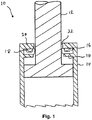
- Figure 1 shows a cross section of a conventional shock absorber 10 comprising a piston 12 slidingly disposed within a cylinder 14.
- a dynamic seal 16 known in the art as a scraper seal or an extruder seal is provided at the neck of the cylinder 14.
- the seal 16 is coupled to or integrated into the cylinder 14 so that its position is fixed relative to the cylinder 14.
- a flange 20 is provided at the neck of the cylinder 14 which prevents extrusion of the seal outside of the chamber 14 during relative movement of the piston 12 and cylinder 14.
- a lower flange 19 may also be provided below the seal 16 such that the flange 20 and lower flange 19 prevent movement of the seal 16 relative to the longitudinal axis of the cylinder.
- the seal 16 may be installed into the grove formed by the flange 20 and lower flange 19, the seal 16 preferably having a very tight fit.
- the flange 20 also prevents larger objects from entering the cylinder 14 through the gap between the outer surface of the piston 12 and the inner surface of the cylinder 14.
- the flange 20 extends so that it is proximal to the outer surface of the piston 12, leaving a very small gap 22 between the inner edge of the flange and the outer circumference of the piston 12.
- This gap 22 may be engineered to accommodate for deflections in the piston 12 during normal use such that during maximum lateral deflection of the piston 12, it does not come into contact with the flange 20.
- the gap 22 may be engineered to prevent extrusion of the seal 16 into the gap 22 due to relative movement of the seal 16 and the piston 12.
- the seal is biased into contact with the outer surface of the piston 12 preferably by an energiser 18 integrated into the seal 16, as shown in more detail in Figure 2 .
- the energiser 18 may be made from a metal spring or an elastomer or any other method known in the art could be used to energise the seal 16 so that it remains in contact with the piston 12.
- the outer surface of the piston 12 rubs against the seal 16 which, in addition to preventing contaminants from entering the cylinder 14, also causes the seal 16, which is made of a softer material than the piston 12, to abrade due to friction between the seal 16 and the piston 12.
- the seal 16 is preferably made of a single compound which is chosen so as to be best suited for the sealing or scraping function as required by the application. This material is preferably chosen so as to provide sufficient wear characteristics such that the seal 16 lasts for the lifetime of the shock absorber or until the next overhaul of the shock absorber or landing gear is scheduled. Equally, the material is prefeably soft enough to perform the required sealing function for any particular application. Accordingly, to accommodate for extremes in wear from one shock absorber to the next, the seal 16 is made of a harder, more resilient and thus more expensive material than it would otherwise be required.
- the seal 16 Because of the proximal position of the flange 20 relative to the outer circumference of the piston , in normal use the seal 16 is hardly, if not at all, visible from the outside of the shock absorber 10, and so in order to inspect the seal 16, the shock absorber 10 must be removed from service and dismantled.
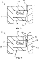
- FIG. 3 an apparatus comprising a seal 116 in accordance with an embodiment of the present invention is shown.
- the seal 116 is coupled to or integrated into a cylinder 114 and is biased into contact with a piston 112 of the shock absorber equivalent to that shown in Figures 1 and 2 .
- an energiser 118 may be provided to bias the seal 116 into contact with the outer surface of the piston 112.
- the seal 116 may be sandwiched between a flange 120 and a lower flange 119 to prevent movement relative to cylinder 114.
- the seal 116 shown in Figure 3 comprises a wear indicator, generally denoted 123, which provides an indication of the amount of wear that the seal has undergone due to relative movement of the piston 112 and the seal 116.
- the seal wear indicator 123 may comprise a notch or indent 124 situated on an outward facing surface, i.e. the surface of the outward facing flat end of the seal 116, at a predetermined distance from the inner edge of the seal 116 such that the wear indicator 123 may be viewed when looking into the neck of the cylinder 114 of the shock absorber 110. Accordingly, as the portion 126 of the seal 116 between the indent 124 and the piston 112 is abraded due to the repeated sliding action of the piston 112 relative to the seal 116, an indication of how much the portion 126 is worn away relative to the notch or indent 124 can be ascertained.
- the indent may comprise a groove running around some or all of the circumference of the seal 116.
- the seal 116 may comprise a portion made of a material with different aesthetic characteristics to the remainder of the seal 116, as denoted in Figure 3 by the hatchings 128 in the inner portion 126 of the seal 116.
- the different material may, for example, be a different colour to the remainder of the seal 116.
- the inner portion 126 may, for example, comprise a material having a different texture, reflectivity characteristic, or any other suitable physical property. This inner portion 126 of the seal 116 may be only partially made of the differing material 128.
- inserts of material having different physical characteristics may be integrated into the seal 116 at particular positions around the inner circumference of the seal 116, the remainder of the inner portion 126 comprising the same material as that of the remainder of the seal 116.
- the seal 116 is worn away by relative movement of the piston 112
- more and more of the material having different aesthetic characteristics will be worn away and in the extreme, all of this material will be worn from the seal 116 thus providing an indication of wear of the seal 116 due to movement relative to the piston 112.
- a flange 120 is also provided in the embodiment illustrated in Figure 3 to prevent larger objects from entering the cavity of the cylinder 114.
- at least a portion of the flange 120 may be cut away to leave a window 122, i.e. a gap, large enough so that the wear indicator can be seen from outside the cylinder casing.
- one or more cutaways 122 may be made in the flange 120 such that small areas of the wear indicator can be seen from outside of the shock absorber 10, whilst the flange still provides protection from larger objects entering the inside of the cylinder 114.
- the flange 120 may be designed such that the gap between the flange 120 and the piston 112 is made larger around the entirety of the circumference of the piston 112 when compared with the flange 20 in Figures 1 and 2 , or the flange 120 may be removed altogether leaving the scraper seal 116 open to the exterior of the shock absorber 10 such that the wear indicator is easily visible from the outside of the shock absorber 10.
- the seal 116 may also act as a guard to larger objects entering the inside of the cylinder cavity 114.
- the seal may be susceptible to extrusion into the clearance gap between the cylinder 114 and piston 112. Accordingly, such an arrangement is undesirable.
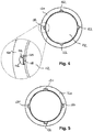
- cutaways 122 are shown situated at intervals around the inner circumference of the flange 120. It will, however, be appreciated that the flange 120 could comprise any number of cutaways and as little as a single cutaway integrated therein.
- having a plurality of points about the diameter of the shock absorber where seal wear can be monitored enables an inspector to better ascertain whether the piston 112 is abrading the seal unevenly, i.e. in one area more than the remainder of the seal 116. Accordingly, an inspector may be able to ascertain whether or not the piston 112 is off centre or the forces applied to the shock absorber 110 are equally balanced. Any imbalance may then be attended to in order to prevent failure of the shock absorber 10.
- the wear indicator can be seen clearly from the exterior of the shock absorber 10 through the cutaway 122. This allows for easy and effective evaluation of the seal condition from the exterior of the shock absorber 10.
- Figure 5 shows an alternative arrangement in which square cutaways 130 are made into the flange 120. It will be appreciated that any shape or configuration of cutaway may be integrated into the flange 120 as long as the wear indicator 123 of the seal 116 can be seen from the exterior of the shock absorber 110. As discussed above, absence or reduction in width of the flange 120 may equally provide the same effect in accordance with embodiments of the present invention.
- the cutaways 112 may be filled with a transparent material such as Perspex (RTM) or glass to provide a window through which an inspector or engineer can see the notch, whilst the flange 120 still provides the full effect of preventing entry of foreign objects into the cavity 114.
- the cutaways 112 may be plugged with a removable plug made from an opaque material, such as steel or another suitable metal. The plug is preferably locked into configuration with the cutaway until inspection of the wear indicator 123 is required.
- support and protection previously provided by the full flange 20 may be at least partially maintained during times in which the wear indicator is not being inspected, thereby reducing the risk of extrusion and unwanted movement of the seal 116.
- a moveable cover may be integrated into the flange to cover the cutaway(s) 112 when there is no requirement to view the wear indicator 123.
- a further embodiment of the present invention comprising a seal 132 having a wear indicator 133 comprising multiple notches 134A, 134B. Accordingly, wear of the seal 123 can be measured relative to each of the notches 134A, 134B so that an engineer or inspector can easily identify the level or wear that the seal 132 has undergone to a greater degree of accuracy.
- a seal 134 which comprises a plurality of portions 136, 138, 140, each having a different aesthetic property.
- portion 140 may be green
- portion 138 may be orange
- portion 136 may be red, thus showing the level of wear of the seal 134 relative to the boundary of each of the colours.
- An inspector can therefore easily identify how much of the seal 134 has worn away and thus whether or not there is a requirement to replace the seal 134.
- by viewing seal wear at a plurality of cutaways 122 around the flange 120 an inspector can quickly identify the amount of uneven wear around the seal 134.
- any combination of features of the wear indicators shown in Figures 6 and 7 could be implemented.
- a plurality of different colour portions each separated by a respective notch, indent or groove could be used to further define and identify wear in a dynamic seal.
Landscapes
- Engineering & Computer Science (AREA)
- General Engineering & Computer Science (AREA)
- Mechanical Engineering (AREA)
- Aviation & Aerospace Engineering (AREA)
- Sealing Devices (AREA)
- Fluid-Damping Devices (AREA)
Description
- This invention relates to an apparatus comprising a sealing element such as a dynamic seal or a bearing.
- Dynamic seals (seals placed between two objects that move relative to one another) are subject to wear throughout their lifetime. For example, a seal coupled to the piston housing of a shock absorber will experience abrasion as it slides over the shock absorber's piston. When designing dynamic seals for shock absorbers used in aircraft landing gear, a conservative approach is usually taken. The seals are designed such that they are sufficiently durable to last for the lifetime of the component into which they are integrated or until an overhaul of that component is scheduled. However, depending on the circumstance, each landing gear is subject to different in-service conditions and, as such, each landing gear shock absorber is subject to a differing amount of accumulative travel. Some landing gears may therefore be subject to more accumulative shock absorber travel than predicted and as a consequence, excessive seal wear may lead to seal leakage and therefore a loss of shock absorber function.
-
GB 1,325,940 - According to a first aspect of the invention, there is provided an apparatus according to
claim 1. - The sealing element may be a seal or a bearing. Where the sealing element is a seal, the wear indicator may be integrated into the seal. Alternatively, where the sealing element is a bearing, the wear indicator may be integrated into the bearing. The bearing may, for instance, have some sealing properties due to its position relative to the second part of the apparatus.
- The apparatus may be a shock absorber or an actuator, in which the first part is a chamber and the second part is a piston slidingly disposed within the chamber. Alternatively, the apparatus may be a journal bearing in which the first part is a collar and the second part is a journal or shaft rotatably mounted within the collar. In both cases, the sealing element may be disposed between the first and second parts, the second part moveable either linearly or by rotation relative to the first part and the sealing element. The apparatus may, in particular, be incorporated in to aircraft and more specifically, aircraft landing gear.
- The wear indicator may comprise an indent, or notch or groove in the top surface of the sealing element situated a predetermined distance from the edge of the sealing element in contact with the second part. Accordingly, as the sealing element is abraded by the second part, the level of wear can be monitored relative to the indent. In addition or alternatively, portions of the wear indicator may comprise material having different aesthetic properties to that of the remainder of the sealing element. For example, a portion of differing material may be situated at the edge of the sealing element in contact with the second part such that once worn away, a visual inspection of the sealing element would indicate that the sealing element has abraded to an unacceptable level requiring the sealing element to be replaced. A plurality of portions of the sealing element may be provided each having different aesthetic properties and being positioned at different distances from the inside edge of the sealing element in order to increase the accuracy of the indication of wear.
- Optionally, indents may be provided between respective differing material portions of the wear indicator to further define the areas having different aesthetic properties.
- The apparatus further comprise one or more flanges proximal to an outer surface of the second part, thus providing a barrier to prevent debris from entering any interior enclosure defined by the second part, in which the flange has one or more windows to allow visual inspection of the wear indicator. The windows may be in the form of a recess or hole in the flange and may optionally be filled with a transparent material such that debris cannot pass through the window. Optionally, an element such as a door may be provided to cover one or more of the windows during times where visual inspection of the wear indicator is not required.
- According to a second aspect of the invention, there is provided an aircraft or aircraft landing gear comprising an apparatus as described above.
- Embodiments of the present invention will now be described, by non-limiting example only, with reference to the accompanying drawings, in which:
-
Figure 1 is a cross section of a piston and housing arrangement including a sealing element; -
Figure 2 is a cross section of the arrangement shown inFigure 1 showing the sealing element in more detail; -
Figure 3 is a close up cross section of an apparatus according to an embodiment of the present invention including a sealing element; -
Figure 4 is a top view of the apparatus shown inFigure 3 ; -
Figure 5 is a top view of a variation of the apparatus shown inFigures 3 and4 ; -
Figure 6 is a cross sectional view of a further variation of the apparatus shown inFigures 3 and4 ; -
Figure 7 is a cross sectional view of a further variation of the apparatus shown inFigures 3 and4 ; - Wear in aircraft landing gear shock absorbers and actuators can currently not easily be inspected when the landing gear is in service. Accordingly, sealing elements are often over-engineered to accommodate for excess wear due to variations in in-service conditions. Embodiments of the present invention enables straightforward, in-service inspection of wear which may take place as part of a normal landing gear check by an engineer or safety inspector.
- The present invention will now be described with reference to a shock absorber which may be present in an aircraft landing gear. It will, however, be appreciated that the present invention may also be applicable to any system in which a dynamic seal is placed against a sliding or rotating body. For example, seal wear indicators described in the following passages may be implemented on seals for actuators and/or seals in bearings and journal arrangements in which a rod rotates within a collar. Equally, embodiments of the present invention are not limited to use with dynamic seals per se. For instance, embodiments described herein may be incorporated into any element placed against a sliding or rotating body, such as bearings not having seals incorporated therein, but instead having inherent sealing characteristics. Accordingly, the term "sealing element", in addition to including dynamic seals, may include bearings which themselves may have some innate sealing property due to their proximity to sliding or rotating bodies. An example of such a configuration is the bearing situated within a shock absorber operable to maintain a rod in a central orientation relative to a housing. The bearing may be subject to wear due to friction between its inner edge and the piston rod. Wear indicators described herein may be integrated into the bearing as described in the same way as described below for dynamic seals.
- It will also be appreciated that whilst embodiments of the present invention are described with reference to aircraft landing gear components, the present invention may be equally applicable in areas outside of the aerospace field.
-
Figure 1 shows a cross section of aconventional shock absorber 10 comprising apiston 12 slidingly disposed within acylinder 14. In order to prevent dirt and other contaminants from entering the internals of thechamber 14, adynamic seal 16 known in the art as a scraper seal or an extruder seal is provided at the neck of thecylinder 14. Theseal 16 is coupled to or integrated into thecylinder 14 so that its position is fixed relative to thecylinder 14. Aflange 20 is provided at the neck of thecylinder 14 which prevents extrusion of the seal outside of thechamber 14 during relative movement of thepiston 12 andcylinder 14. Alower flange 19 may also be provided below theseal 16 such that theflange 20 andlower flange 19 prevent movement of theseal 16 relative to the longitudinal axis of the cylinder. In such circumstances, theseal 16 may be installed into the grove formed by theflange 20 andlower flange 19, theseal 16 preferably having a very tight fit. Theflange 20 also prevents larger objects from entering thecylinder 14 through the gap between the outer surface of thepiston 12 and the inner surface of thecylinder 14. Theflange 20 extends so that it is proximal to the outer surface of thepiston 12, leaving a verysmall gap 22 between the inner edge of the flange and the outer circumference of thepiston 12. Thisgap 22 may be engineered to accommodate for deflections in thepiston 12 during normal use such that during maximum lateral deflection of thepiston 12, it does not come into contact with theflange 20. In addition or alternatively, thegap 22 may be engineered to prevent extrusion of theseal 16 into thegap 22 due to relative movement of theseal 16 and thepiston 12. - The seal is biased into contact with the outer surface of the
piston 12 preferably by anenergiser 18 integrated into theseal 16, as shown in more detail inFigure 2 . Theenergiser 18 may be made from a metal spring or an elastomer or any other method known in the art could be used to energise theseal 16 so that it remains in contact with thepiston 12. As thepiston 12 slides in and out of thecylinder 14 the outer surface of thepiston 12 rubs against theseal 16 which, in addition to preventing contaminants from entering thecylinder 14, also causes theseal 16, which is made of a softer material than thepiston 12, to abrade due to friction between theseal 16 and thepiston 12. Theseal 16 is preferably made of a single compound which is chosen so as to be best suited for the sealing or scraping function as required by the application. This material is preferably chosen so as to provide sufficient wear characteristics such that theseal 16 lasts for the lifetime of the shock absorber or until the next overhaul of the shock absorber or landing gear is scheduled. Equally, the material is prefeably soft enough to perform the required sealing function for any particular application. Accordingly, to accommodate for extremes in wear from one shock absorber to the next, theseal 16 is made of a harder, more resilient and thus more expensive material than it would otherwise be required. - Because of the proximal position of the
flange 20 relative to the outer circumference of the piston , in normal use theseal 16 is hardly, if not at all, visible from the outside of theshock absorber 10, and so in order to inspect theseal 16, theshock absorber 10 must be removed from service and dismantled. - Referring now to
Figure 3 , an apparatus comprising aseal 116 in accordance with an embodiment of the present invention is shown. Theseal 116 is coupled to or integrated into acylinder 114 and is biased into contact with apiston 112 of the shock absorber equivalent to that shown inFigures 1 and2 . As with theprior art seal 16, an energiser 118 may be provided to bias theseal 116 into contact with the outer surface of thepiston 112. In addition, as with the seal shown inFigures 1 and2 , theseal 116 may be sandwiched between aflange 120 and alower flange 119 to prevent movement relative tocylinder 114. However in contrast to theprior art seal 12, theseal 116 shown inFigure 3 comprises a wear indicator, generally denoted 123, which provides an indication of the amount of wear that the seal has undergone due to relative movement of thepiston 112 and theseal 116. - The seal wear
indicator 123 may comprise a notch orindent 124 situated on an outward facing surface, i.e. the surface of the outward facing flat end of theseal 116, at a predetermined distance from the inner edge of theseal 116 such that thewear indicator 123 may be viewed when looking into the neck of thecylinder 114 of theshock absorber 110. Accordingly, as theportion 126 of theseal 116 between theindent 124 and thepiston 112 is abraded due to the repeated sliding action of thepiston 112 relative to theseal 116, an indication of how much theportion 126 is worn away relative to the notch orindent 124 can be ascertained. Optionally, the indent may comprise a groove running around some or all of the circumference of theseal 116. - In addition or in place of the indent or notch 124, in order to provide an indication of seal wear, the
seal 116 may comprise a portion made of a material with different aesthetic characteristics to the remainder of theseal 116, as denoted inFigure 3 by thehatchings 128 in theinner portion 126 of theseal 116. The different material may, for example, be a different colour to the remainder of theseal 116. In addition or alternatively, theinner portion 126 may, for example, comprise a material having a different texture, reflectivity characteristic, or any other suitable physical property. Thisinner portion 126 of theseal 116 may be only partially made of thediffering material 128. For example, inserts of material having different physical characteristics may be integrated into theseal 116 at particular positions around the inner circumference of theseal 116, the remainder of theinner portion 126 comprising the same material as that of the remainder of theseal 116. In any case, as theseal 116 is worn away by relative movement of thepiston 112, more and more of the material having different aesthetic characteristics will be worn away and in the extreme, all of this material will be worn from theseal 116 thus providing an indication of wear of theseal 116 due to movement relative to thepiston 112. - As discussed in connection with the
shock absorber 10 shown inFigure 1 , aflange 120 is also provided in the embodiment illustrated inFigure 3 to prevent larger objects from entering the cavity of thecylinder 114. However, in contrast toFigure 1 , at least a portion of theflange 120 may be cut away to leave awindow 122, i.e. a gap, large enough so that the wear indicator can be seen from outside the cylinder casing. As shown in more detail inFigure 4 , one ormore cutaways 122 may be made in theflange 120 such that small areas of the wear indicator can be seen from outside of theshock absorber 10, whilst the flange still provides protection from larger objects entering the inside of thecylinder 114. In other embodiments, however, theflange 120 may be designed such that the gap between theflange 120 and thepiston 112 is made larger around the entirety of the circumference of thepiston 112 when compared with theflange 20 inFigures 1 and2 , or theflange 120 may be removed altogether leaving thescraper seal 116 open to the exterior of theshock absorber 10 such that the wear indicator is easily visible from the outside of theshock absorber 10. In such embodiments, theseal 116 may also act as a guard to larger objects entering the inside of thecylinder cavity 114. However, in such an embodiment, the seal may be susceptible to extrusion into the clearance gap between thecylinder 114 andpiston 112. Accordingly, such an arrangement is undesirable. - Referring again to
Figure 4 ,cutaways 122 are shown situated at intervals around the inner circumference of theflange 120. It will, however, be appreciated that theflange 120 could comprise any number of cutaways and as little as a single cutaway integrated therein. However, having a plurality of points about the diameter of the shock absorber where seal wear can be monitored enables an inspector to better ascertain whether thepiston 112 is abrading the seal unevenly, i.e. in one area more than the remainder of theseal 116. Accordingly, an inspector may be able to ascertain whether or not thepiston 112 is off centre or the forces applied to theshock absorber 110 are equally balanced. Any imbalance may then be attended to in order to prevent failure of theshock absorber 10. As can be seen from the magnified area ofFigure 4 , the wear indicator can be seen clearly from the exterior of theshock absorber 10 through thecutaway 122. This allows for easy and effective evaluation of the seal condition from the exterior of theshock absorber 10. -
Figure 5 shows an alternative arrangement in whichsquare cutaways 130 are made into theflange 120. It will be appreciated that any shape or configuration of cutaway may be integrated into theflange 120 as long as thewear indicator 123 of theseal 116 can be seen from the exterior of theshock absorber 110. As discussed above, absence or reduction in width of theflange 120 may equally provide the same effect in accordance with embodiments of the present invention. - In order to further prevent larger objects from entering the cavity of the
cylinder 114, thecutaways 112 may be filled with a transparent material such as Perspex (RTM) or glass to provide a window through which an inspector or engineer can see the notch, whilst theflange 120 still provides the full effect of preventing entry of foreign objects into thecavity 114. Alternatively, thecutaways 112 may be plugged with a removable plug made from an opaque material, such as steel or another suitable metal. The plug is preferably locked into configuration with the cutaway until inspection of thewear indicator 123 is required. By plugging the cutaway 112 either with transparent material or with a removable opaque plug, support and protection previously provided by thefull flange 20 may be at least partially maintained during times in which the wear indicator is not being inspected, thereby reducing the risk of extrusion and unwanted movement of theseal 116. - In addition or alternatively, a moveable cover (folding, sliding or otherwise) may be integrated into the flange to cover the cutaway(s) 112 when there is no requirement to view the
wear indicator 123. - Referring now to
Figure 6 , a further embodiment of the present invention is shown comprising aseal 132 having a wear indicator 133 comprising multiple notches 134A, 134B. Accordingly, wear of theseal 123 can be measured relative to each of the notches 134A, 134B so that an engineer or inspector can easily identify the level or wear that theseal 132 has undergone to a greater degree of accuracy. - Similarly, referring to
figure 7 , a seal 134 is shown which comprises a plurality ofportions example portion 140 may be green,portion 138 may be orange, andportion 136 may be red, thus showing the level of wear of the seal 134 relative to the boundary of each of the colours. An inspector can therefore easily identify how much of the seal 134 has worn away and thus whether or not there is a requirement to replace the seal 134. Furthermore, by viewing seal wear at a plurality ofcutaways 122 around theflange 120, an inspector can quickly identify the amount of uneven wear around the seal 134. It will be appreciated that any combination of features of the wear indicators shown inFigures 6 and 7 could be implemented. For example, a plurality of different colour portions each separated by a respective notch, indent or groove could be used to further define and identify wear in a dynamic seal.
Claims (13)
- An apparatus, comprising:a first part (14) arranged to receive a second part (12); anda sealing element (16) disposed between the first part and the second part and in contact with the second part, the second part arranged to be moveable relative to the first part and the sealing element, wherein the sealing element comprises a wear indicator (123), and the first part is configured such that the wear indicator is visible external to the apparatus in normal use,characterised in that the first part comprises a flange (20) proximal to an outer surface of the second part, the flange having one or more windows (122) to allow visual inspection of the wear indicator.
- An apparatus as claimed in claim 1, wherein the sealing element (16) comprises a seal (116) or a bearing.
- An apparatus as claimed in claims 1 or 2, wherein the apparatus is a shock absorber (10) or an actuator, the first part is a piston housing and the second part is a piston slidingly disposed relative to a chamber of the piston housing.
- An apparatus according to claims 1 or 2, wherein the first part is a collar and the second part is a rod rotatably mounted within the collar.
- An apparatus as claimed in any of claims 1 to 3, wherein the wear indicator comprises a first indent (124) in the sealing element arranged to indicate an amount of wear of the sealing element relative to the indent.
- An apparatus according to claim 5, further comprising one or more additional indents (124) arranged concentrically relative to the first indent.
- An apparatus as claimed in any preceding claim, wherein the sealing element comprises two or more adjacent portions having different aesthetic appearances and arranged to indicate an amount of wear of the sealing element relative to borders between adjacent portions.
- An apparatus according to claim 7 wherein at least two of the two or more adjacent portions are separated by indents in the surface of the sealing element.
- An apparatus as claimed in claim 1, wherein one or more of the windows (122) comprises a recess in the flange (20).
- An apparatus as claimed in claims 1 or 9, wherein one or more of the windows (122) comprises a transparent material.
- An apparatus as claimed in claims 1 or 9, further comprising a removable plug adapted to substantially plug the window (122).
- An apparatus as claimed in any of claims 1 to 11, further comprising an element coupled to the flange, moveable between a first position in which the element covers one or more of the windows and a second position in which the one or more windows is visible from outside of the apparatus.
- An aircraft landing gear comprising an apparatus according to any preceding claim.
Applications Claiming Priority (2)
| Application Number | Priority Date | Filing Date | Title |
|---|---|---|---|
| GB1314046.2A GB2516119B (en) | 2013-08-06 | 2013-08-06 | An Apparatus Comprising a Sealing Element |
| PCT/GB2014/052168 WO2015019049A1 (en) | 2013-08-06 | 2014-07-16 | An apparatus comprising a sealing element |
Publications (2)
| Publication Number | Publication Date |
|---|---|
| EP3030814A1 EP3030814A1 (en) | 2016-06-15 |
| EP3030814B1 true EP3030814B1 (en) | 2017-08-23 |
Family
ID=49224223
Family Applications (1)
| Application Number | Title | Priority Date | Filing Date |
|---|---|---|---|
| EP14749949.5A Active EP3030814B1 (en) | 2013-08-06 | 2014-07-16 | An apparatus comprising a sealing element |
Country Status (5)
| Country | Link |
|---|---|
| US (1) | US20160178064A1 (en) |
| EP (1) | EP3030814B1 (en) |
| CA (1) | CA2919538C (en) |
| GB (1) | GB2516119B (en) |
| WO (1) | WO2015019049A1 (en) |
Families Citing this family (8)
| Publication number | Priority date | Publication date | Assignee | Title |
|---|---|---|---|---|
| FR3023613B1 (en) * | 2014-07-09 | 2016-07-15 | Messier Bugatti Dowty | METHOD FOR DETECTING A LEAKAGE OF A DYNAMIC JOINT IN AN AIRCRAFT ENGINE |
| US10591013B2 (en) * | 2017-06-14 | 2020-03-17 | Safran Landing Systems Canada Inc. | Lubrication mechanism design for aircraft landing gear bearings |
| US10260589B2 (en) * | 2017-07-13 | 2019-04-16 | GM Global Technology Operations LLC | Gas strut |
| US11193591B2 (en) | 2017-08-03 | 2021-12-07 | Raytheon Technologies Corporation | Seal sacrificial wear indicator |
| US11112348B2 (en) | 2019-03-26 | 2021-09-07 | Hamilton Sundstrand Corporation | Wear sensors for monitoring seal wear in bearing arrangements |
| US20220018483A1 (en) * | 2020-07-16 | 2022-01-20 | Saudi Arabian Oil Company | Pipeline scraper assemblies including wear indicators and methods for using the same |
| US11401832B2 (en) | 2021-01-05 | 2022-08-02 | Raytheon Technologies Corporation | Gas turbine engine including seal plate with separable tabs |
| US12461023B2 (en) * | 2022-08-05 | 2025-11-04 | Caterpillar Inc. | Subsurface underlying incipient failure indicator in wear components |
Family Cites Families (42)
| Publication number | Priority date | Publication date | Assignee | Title |
|---|---|---|---|---|
| US697965A (en) * | 1901-05-03 | 1902-04-22 | Edwin E Baldwin | Piston. |
| US2102784A (en) * | 1936-02-06 | 1937-12-21 | Socony Vacuum Oil Co Inc | Method of making a wear indicating tire |
| US3138224A (en) * | 1962-04-30 | 1964-06-23 | Andrew J White | Brake having means to indicate wear |
| GB1350752A (en) * | 1970-04-03 | 1974-04-24 | Sykes Ltd Henry | Rotary shaft seal |
| US3756754A (en) * | 1970-10-24 | 1973-09-04 | Nippon Piston Ring Co Ltd | Apex seal for rotary piston engine |
| US3870607A (en) * | 1971-04-21 | 1975-03-11 | Avco Corp | Bearing Manufacture |
| GB1325940A (en) * | 1971-07-27 | 1973-08-08 | Crane Packing Ltd | Rotary mechanical face seals |
| US3897116A (en) * | 1971-10-07 | 1975-07-29 | Crane Co | Bearing wear detector |
| US3752607A (en) * | 1972-03-06 | 1973-08-14 | Gen Motors Corp | Rotary machine apex seal |
| US3842792A (en) * | 1973-09-04 | 1974-10-22 | L Souther | Seal wear indicating mechanisms |
| AU512607B2 (en) * | 1977-02-07 | 1980-10-16 | Exxon Research And Engineering Company | Nondestructive erosion indicator |
| US4282925A (en) * | 1980-03-26 | 1981-08-11 | Franrica Mfg. Inc. | Scraped surface heat exchanger |
| US4567972A (en) * | 1984-01-06 | 1986-02-04 | Teledyne Mid-America Corporation | Clutch wear detector, adjustment and indicator system |
| US4814664A (en) * | 1988-02-16 | 1989-03-21 | Champion Spark Plug Company | Igniter with wear indicator |
| US5451110A (en) * | 1993-12-28 | 1995-09-19 | Syedala Industries, Inc. | Bearing wear indicator |
| JP3263836B2 (en) * | 1994-04-26 | 2002-03-11 | 日清紡績株式会社 | Drum brake device |
| US5579717A (en) * | 1994-10-13 | 1996-12-03 | International Business Machines Corporation | Method of grinding thin-film magnetic heads using optical grinding markers |
| JPH08247296A (en) * | 1995-03-07 | 1996-09-24 | Mitsubishi Motors Corp | Oil seal structure |
| US5549156A (en) * | 1995-06-06 | 1996-08-27 | Borden; B. Michael | Shock absorber & Wiper |
| US5746891A (en) * | 1996-07-25 | 1998-05-05 | Withers; William David | Wear indicators for seal strip of a suction roll of a paper making machine |
| US6626436B2 (en) * | 1997-08-20 | 2003-09-30 | Crane John Inc | Monitoring seal system |
| US6595523B1 (en) * | 1998-06-03 | 2003-07-22 | Ralph Heinzen | Self monitoring mechanical seal |
| US7405818B2 (en) * | 1998-06-03 | 2008-07-29 | Ralph Heinzen | Self monitoring static seal with optical sensor |
| US6237723B1 (en) * | 1999-09-02 | 2001-05-29 | Tony W. Salsman | Quick check brake indicator |
| DE10000853A1 (en) * | 2000-01-12 | 2001-08-02 | Freudenberg Carl Fa | Ring seal has a sealing lip with a structured curvature and at least one opening which gives a flow link to the ambient atmosphere only on a faulty installation as an immediate indication of an incorrect fitting |
| US6394023B1 (en) * | 2000-03-27 | 2002-05-28 | Applied Materials, Inc. | Process kit parts and method for using same |
| US6676076B1 (en) * | 2002-12-12 | 2004-01-13 | The Boeing Company | Two stage shock strut |
| US7334330B2 (en) * | 2004-04-28 | 2008-02-26 | Siemens Power Generation, Inc. | Thermally insulating layer incorporating a distinguishing agent and method for inspecting the same |
| US20090084638A1 (en) * | 2004-12-30 | 2009-04-02 | Masterson Steven J | Disc brake pad with visual wear indicator |
| FR2880667A1 (en) * | 2005-01-10 | 2006-07-14 | Air Liquide | Sealing O-joint for e.g. fluid transferring fitting, has body partly covered by coating layer which is not placed at certain locations of body and formed of painted layer or colored rubber |
| US7424936B2 (en) * | 2005-11-17 | 2008-09-16 | Mcclellan William Thomas | Brake pad with wear indicator |
| US20080251326A1 (en) * | 2007-04-16 | 2008-10-16 | Lundskog David A | Disc brake pads having a visual wear indicator which signals the need for pad replacement |
| DE102007036271A1 (en) * | 2007-07-31 | 2009-02-05 | Baumer Hübner GmbH | Encoder with monitoring of bearing wear and method |
| US7847679B2 (en) * | 2007-10-26 | 2010-12-07 | Rolls-Royce Corporation | Material wear indication system |
| JP2010107375A (en) * | 2008-10-30 | 2010-05-13 | Mitsui Eng & Shipbuild Co Ltd | Piston check gauge |
| US8448949B2 (en) * | 2009-08-13 | 2013-05-28 | Parker-Hannifin Corporation | Sealing assembly with integral sensor |
| US8960378B2 (en) * | 2010-04-02 | 2015-02-24 | Ashima Ltd. | Brake block for bicycle |
| US8893855B2 (en) * | 2011-04-18 | 2014-11-25 | Northern Tool & Equipment Company, Inc. | Bearing protection with positive lubricant-level indication |
| US9541199B2 (en) * | 2011-04-25 | 2017-01-10 | Bal Seal Engineering, Inc. | Seal failure detection systems and related methods |
| DE102011082574A1 (en) * | 2011-09-13 | 2013-03-14 | Schaeffler Technologies AG & Co. KG | Dynamic seal arrangement for movably sealing e.g. outer ring of rolling bearing, has resilient sealing element arranged between two components that are movable relative to each other, where sealing element comprises wear indicator |
| DE102013205912A1 (en) * | 2013-04-04 | 2014-10-09 | Federal-Mogul Burscheid Gmbh | Piston ring with wear indicator |
| US10035251B2 (en) * | 2015-11-13 | 2018-07-31 | Caterpillar Inc. | Wear indicating system |
-
2013
- 2013-08-06 GB GB1314046.2A patent/GB2516119B/en not_active Expired - Fee Related
-
2014
- 2014-07-16 EP EP14749949.5A patent/EP3030814B1/en active Active
- 2014-07-16 CA CA2919538A patent/CA2919538C/en active Active
- 2014-07-16 US US14/909,618 patent/US20160178064A1/en not_active Abandoned
- 2014-07-16 WO PCT/GB2014/052168 patent/WO2015019049A1/en not_active Ceased
Non-Patent Citations (1)
| Title |
|---|
| None * |
Also Published As
| Publication number | Publication date |
|---|---|
| US20160178064A1 (en) | 2016-06-23 |
| GB2516119B (en) | 2015-06-24 |
| GB201314046D0 (en) | 2013-09-18 |
| GB2516119A (en) | 2015-01-14 |
| WO2015019049A1 (en) | 2015-02-12 |
| CA2919538C (en) | 2019-10-22 |
| EP3030814A1 (en) | 2016-06-15 |
| CA2919538A1 (en) | 2015-02-12 |
Similar Documents
| Publication | Publication Date | Title |
|---|---|---|
| CA2919538C (en) | An apparatus comprising a sealing element | |
| WO2011093922A1 (en) | Bearing assembly with extended maintenance interval | |
| CN108603602B (en) | Sealing means | |
| KR20190120286A (en) | Silk Hat Type Gear Drive | |
| IT202100029606A1 (en) | BEARING UNIT WITH SEAL DEVICE | |
| DE102013205912A1 (en) | Piston ring with wear indicator | |
| KR20190053855A (en) | Wheel bearing seals with integral pre-seal | |
| IT202100022952A1 (en) | BEARING UNIT WITH PROTECTIVE DISC | |
| DE102016216641A1 (en) | Sealing device for rolling bearing unit | |
| DE102016204979A1 (en) | Capacitance measurement in a bearing housing | |
| DE102016204977A1 (en) | Capacitance measurement in a bearing housing | |
| US20130308995A1 (en) | Ball joint device | |
| US10520095B2 (en) | Abradable seal | |
| EP2963319A1 (en) | Gasket | |
| CA3090306A1 (en) | Ballscrew seal | |
| DK3164625T3 (en) | Press Outlet Scraper Collection | |
| DE102013212960A1 (en) | poetry | |
| US20160341628A1 (en) | Method for monitoring health of a seal | |
| JP6858098B2 (en) | Shaft sealing device | |
| CN214356651U (en) | Undercarriage wheel axle structure | |
| EP3267078A1 (en) | Cassette seal assembly, in particular for vehicle axles | |
| DE10202525A1 (en) | Rotary bearing for rollers for supporting steel rods after casting has antifriction bearing protected on one side by metal caps and cooled using water jacket, and skimmers having elements with metal lips on smooth metallic counter race | |
| EP3450802B1 (en) | Rotary seal | |
| ITTO20040133U1 (en) | HOLDING DEVICE FOR BEARINGS | |
| EP1920177B1 (en) | Bearing isolator with porous seal |
Legal Events
| Date | Code | Title | Description |
|---|---|---|---|
| PUAI | Public reference made under article 153(3) epc to a published international application that has entered the european phase |
Free format text: ORIGINAL CODE: 0009012 |
|
| 17P | Request for examination filed |
Effective date: 20160120 |
|
| AK | Designated contracting states |
Kind code of ref document: A1 Designated state(s): AL AT BE BG CH CY CZ DE DK EE ES FI FR GB GR HR HU IE IS IT LI LT LU LV MC MK MT NL NO PL PT RO RS SE SI SK SM TR |
|
| AX | Request for extension of the european patent |
Extension state: BA ME |
|
| DAX | Request for extension of the european patent (deleted) | ||
| RAP1 | Party data changed (applicant data changed or rights of an application transferred) |
Owner name: SAFRAN LANDING SYSTEMS UK LTD |
|
| REG | Reference to a national code |
Ref country code: DE Ref legal event code: R079 Ref document number: 602014013554 Country of ref document: DE Free format text: PREVIOUS MAIN CLASS: F16J0015320000 Ipc: F16J0015329600 |
|
| GRAP | Despatch of communication of intention to grant a patent |
Free format text: ORIGINAL CODE: EPIDOSNIGR1 |
|
| STAA | Information on the status of an ep patent application or granted ep patent |
Free format text: STATUS: GRANT OF PATENT IS INTENDED |
|
| RIC1 | Information provided on ipc code assigned before grant |
Ipc: F16F 9/36 20060101ALI20170207BHEP Ipc: B64C 25/60 20060101ALI20170207BHEP Ipc: F16J 15/3296 20160101AFI20170207BHEP |
|
| INTG | Intention to grant announced |
Effective date: 20170303 |
|
| GRAS | Grant fee paid |
Free format text: ORIGINAL CODE: EPIDOSNIGR3 |
|
| GRAA | (expected) grant |
Free format text: ORIGINAL CODE: 0009210 |
|
| STAA | Information on the status of an ep patent application or granted ep patent |
Free format text: STATUS: THE PATENT HAS BEEN GRANTED |
|
| AK | Designated contracting states |
Kind code of ref document: B1 Designated state(s): AL AT BE BG CH CY CZ DE DK EE ES FI FR GB GR HR HU IE IS IT LI LT LU LV MC MK MT NL NO PL PT RO RS SE SI SK SM TR |
|
| REG | Reference to a national code |
Ref country code: GB Ref legal event code: FG4D |
|
| REG | Reference to a national code |
Ref country code: CH Ref legal event code: EP |
|
| REG | Reference to a national code |
Ref country code: AT Ref legal event code: REF Ref document number: 921705 Country of ref document: AT Kind code of ref document: T Effective date: 20170915 |
|
| REG | Reference to a national code |
Ref country code: IE Ref legal event code: FG4D |
|
| REG | Reference to a national code |
Ref country code: DE Ref legal event code: R096 Ref document number: 602014013554 Country of ref document: DE |
|
| REG | Reference to a national code |
Ref country code: NL Ref legal event code: MP Effective date: 20170823 |
|
| REG | Reference to a national code |
Ref country code: LT Ref legal event code: MG4D |
|
| REG | Reference to a national code |
Ref country code: AT Ref legal event code: MK05 Ref document number: 921705 Country of ref document: AT Kind code of ref document: T Effective date: 20170823 |
|
| PG25 | Lapsed in a contracting state [announced via postgrant information from national office to epo] |
Ref country code: SE Free format text: LAPSE BECAUSE OF FAILURE TO SUBMIT A TRANSLATION OF THE DESCRIPTION OR TO PAY THE FEE WITHIN THE PRESCRIBED TIME-LIMIT Effective date: 20170823 Ref country code: HR Free format text: LAPSE BECAUSE OF FAILURE TO SUBMIT A TRANSLATION OF THE DESCRIPTION OR TO PAY THE FEE WITHIN THE PRESCRIBED TIME-LIMIT Effective date: 20170823 Ref country code: AT Free format text: LAPSE BECAUSE OF FAILURE TO SUBMIT A TRANSLATION OF THE DESCRIPTION OR TO PAY THE FEE WITHIN THE PRESCRIBED TIME-LIMIT Effective date: 20170823 Ref country code: NL Free format text: LAPSE BECAUSE OF FAILURE TO SUBMIT A TRANSLATION OF THE DESCRIPTION OR TO PAY THE FEE WITHIN THE PRESCRIBED TIME-LIMIT Effective date: 20170823 Ref country code: LT Free format text: LAPSE BECAUSE OF FAILURE TO SUBMIT A TRANSLATION OF THE DESCRIPTION OR TO PAY THE FEE WITHIN THE PRESCRIBED TIME-LIMIT Effective date: 20170823 Ref country code: NO Free format text: LAPSE BECAUSE OF FAILURE TO SUBMIT A TRANSLATION OF THE DESCRIPTION OR TO PAY THE FEE WITHIN THE PRESCRIBED TIME-LIMIT Effective date: 20171123 Ref country code: FI Free format text: LAPSE BECAUSE OF FAILURE TO SUBMIT A TRANSLATION OF THE DESCRIPTION OR TO PAY THE FEE WITHIN THE PRESCRIBED TIME-LIMIT Effective date: 20170823 |
|
| PG25 | Lapsed in a contracting state [announced via postgrant information from national office to epo] |
Ref country code: ES Free format text: LAPSE BECAUSE OF FAILURE TO SUBMIT A TRANSLATION OF THE DESCRIPTION OR TO PAY THE FEE WITHIN THE PRESCRIBED TIME-LIMIT Effective date: 20170823 Ref country code: RS Free format text: LAPSE BECAUSE OF FAILURE TO SUBMIT A TRANSLATION OF THE DESCRIPTION OR TO PAY THE FEE WITHIN THE PRESCRIBED TIME-LIMIT Effective date: 20170823 Ref country code: BG Free format text: LAPSE BECAUSE OF FAILURE TO SUBMIT A TRANSLATION OF THE DESCRIPTION OR TO PAY THE FEE WITHIN THE PRESCRIBED TIME-LIMIT Effective date: 20171123 Ref country code: PL Free format text: LAPSE BECAUSE OF FAILURE TO SUBMIT A TRANSLATION OF THE DESCRIPTION OR TO PAY THE FEE WITHIN THE PRESCRIBED TIME-LIMIT Effective date: 20170823 Ref country code: LV Free format text: LAPSE BECAUSE OF FAILURE TO SUBMIT A TRANSLATION OF THE DESCRIPTION OR TO PAY THE FEE WITHIN THE PRESCRIBED TIME-LIMIT Effective date: 20170823 Ref country code: GR Free format text: LAPSE BECAUSE OF FAILURE TO SUBMIT A TRANSLATION OF THE DESCRIPTION OR TO PAY THE FEE WITHIN THE PRESCRIBED TIME-LIMIT Effective date: 20171124 Ref country code: IS Free format text: LAPSE BECAUSE OF FAILURE TO SUBMIT A TRANSLATION OF THE DESCRIPTION OR TO PAY THE FEE WITHIN THE PRESCRIBED TIME-LIMIT Effective date: 20171223 |
|
| PG25 | Lapsed in a contracting state [announced via postgrant information from national office to epo] |
Ref country code: DK Free format text: LAPSE BECAUSE OF FAILURE TO SUBMIT A TRANSLATION OF THE DESCRIPTION OR TO PAY THE FEE WITHIN THE PRESCRIBED TIME-LIMIT Effective date: 20170823 Ref country code: CZ Free format text: LAPSE BECAUSE OF FAILURE TO SUBMIT A TRANSLATION OF THE DESCRIPTION OR TO PAY THE FEE WITHIN THE PRESCRIBED TIME-LIMIT Effective date: 20170823 Ref country code: RO Free format text: LAPSE BECAUSE OF FAILURE TO SUBMIT A TRANSLATION OF THE DESCRIPTION OR TO PAY THE FEE WITHIN THE PRESCRIBED TIME-LIMIT Effective date: 20170823 |
|
| REG | Reference to a national code |
Ref country code: DE Ref legal event code: R097 Ref document number: 602014013554 Country of ref document: DE |
|
| PG25 | Lapsed in a contracting state [announced via postgrant information from national office to epo] |
Ref country code: SM Free format text: LAPSE BECAUSE OF FAILURE TO SUBMIT A TRANSLATION OF THE DESCRIPTION OR TO PAY THE FEE WITHIN THE PRESCRIBED TIME-LIMIT Effective date: 20170823 Ref country code: IT Free format text: LAPSE BECAUSE OF FAILURE TO SUBMIT A TRANSLATION OF THE DESCRIPTION OR TO PAY THE FEE WITHIN THE PRESCRIBED TIME-LIMIT Effective date: 20170823 Ref country code: SK Free format text: LAPSE BECAUSE OF FAILURE TO SUBMIT A TRANSLATION OF THE DESCRIPTION OR TO PAY THE FEE WITHIN THE PRESCRIBED TIME-LIMIT Effective date: 20170823 Ref country code: EE Free format text: LAPSE BECAUSE OF FAILURE TO SUBMIT A TRANSLATION OF THE DESCRIPTION OR TO PAY THE FEE WITHIN THE PRESCRIBED TIME-LIMIT Effective date: 20170823 |
|
| PLBE | No opposition filed within time limit |
Free format text: ORIGINAL CODE: 0009261 |
|
| STAA | Information on the status of an ep patent application or granted ep patent |
Free format text: STATUS: NO OPPOSITION FILED WITHIN TIME LIMIT |
|
| REG | Reference to a national code |
Ref country code: FR Ref legal event code: PLFP Year of fee payment: 5 |
|
| 26N | No opposition filed |
Effective date: 20180524 |
|
| PG25 | Lapsed in a contracting state [announced via postgrant information from national office to epo] |
Ref country code: SI Free format text: LAPSE BECAUSE OF FAILURE TO SUBMIT A TRANSLATION OF THE DESCRIPTION OR TO PAY THE FEE WITHIN THE PRESCRIBED TIME-LIMIT Effective date: 20170823 |
|
| REG | Reference to a national code |
Ref country code: CH Ref legal event code: PL |
|
| PG25 | Lapsed in a contracting state [announced via postgrant information from national office to epo] |
Ref country code: LU Free format text: LAPSE BECAUSE OF NON-PAYMENT OF DUE FEES Effective date: 20180716 Ref country code: MC Free format text: LAPSE BECAUSE OF FAILURE TO SUBMIT A TRANSLATION OF THE DESCRIPTION OR TO PAY THE FEE WITHIN THE PRESCRIBED TIME-LIMIT Effective date: 20170823 |
|
| REG | Reference to a national code |
Ref country code: BE Ref legal event code: MM Effective date: 20180731 |
|
| REG | Reference to a national code |
Ref country code: IE Ref legal event code: MM4A |
|
| PG25 | Lapsed in a contracting state [announced via postgrant information from national office to epo] |
Ref country code: CH Free format text: LAPSE BECAUSE OF NON-PAYMENT OF DUE FEES Effective date: 20180731 Ref country code: LI Free format text: LAPSE BECAUSE OF NON-PAYMENT OF DUE FEES Effective date: 20180731 Ref country code: IE Free format text: LAPSE BECAUSE OF NON-PAYMENT OF DUE FEES Effective date: 20180716 |
|
| PG25 | Lapsed in a contracting state [announced via postgrant information from national office to epo] |
Ref country code: BE Free format text: LAPSE BECAUSE OF NON-PAYMENT OF DUE FEES Effective date: 20180731 |
|
| PG25 | Lapsed in a contracting state [announced via postgrant information from national office to epo] |
Ref country code: MT Free format text: LAPSE BECAUSE OF NON-PAYMENT OF DUE FEES Effective date: 20180716 |
|
| PG25 | Lapsed in a contracting state [announced via postgrant information from national office to epo] |
Ref country code: TR Free format text: LAPSE BECAUSE OF FAILURE TO SUBMIT A TRANSLATION OF THE DESCRIPTION OR TO PAY THE FEE WITHIN THE PRESCRIBED TIME-LIMIT Effective date: 20170823 |
|
| PG25 | Lapsed in a contracting state [announced via postgrant information from national office to epo] |
Ref country code: PT Free format text: LAPSE BECAUSE OF FAILURE TO SUBMIT A TRANSLATION OF THE DESCRIPTION OR TO PAY THE FEE WITHIN THE PRESCRIBED TIME-LIMIT Effective date: 20170823 |
|
| PG25 | Lapsed in a contracting state [announced via postgrant information from national office to epo] |
Ref country code: CY Free format text: LAPSE BECAUSE OF FAILURE TO SUBMIT A TRANSLATION OF THE DESCRIPTION OR TO PAY THE FEE WITHIN THE PRESCRIBED TIME-LIMIT Effective date: 20170823 Ref country code: MK Free format text: LAPSE BECAUSE OF NON-PAYMENT OF DUE FEES Effective date: 20170823 Ref country code: HU Free format text: LAPSE BECAUSE OF FAILURE TO SUBMIT A TRANSLATION OF THE DESCRIPTION OR TO PAY THE FEE WITHIN THE PRESCRIBED TIME-LIMIT; INVALID AB INITIO Effective date: 20140716 |
|
| PG25 | Lapsed in a contracting state [announced via postgrant information from national office to epo] |
Ref country code: AL Free format text: LAPSE BECAUSE OF FAILURE TO SUBMIT A TRANSLATION OF THE DESCRIPTION OR TO PAY THE FEE WITHIN THE PRESCRIBED TIME-LIMIT Effective date: 20170823 |
|
| PGFP | Annual fee paid to national office [announced via postgrant information from national office to epo] |
Ref country code: DE Payment date: 20250722 Year of fee payment: 12 |
|
| PGFP | Annual fee paid to national office [announced via postgrant information from national office to epo] |
Ref country code: GB Payment date: 20250724 Year of fee payment: 12 |
|
| PGFP | Annual fee paid to national office [announced via postgrant information from national office to epo] |
Ref country code: FR Payment date: 20250722 Year of fee payment: 12 |
|
| REG | Reference to a national code |
Ref country code: DE Ref legal event code: R082 Ref document number: 602014013554 Country of ref document: DE Representative=s name: PATERIS PARTMBB, DE |