EP3029938A1 - Procédé de codage du mouvement dans une séquence vidéo - Google Patents
Procédé de codage du mouvement dans une séquence vidéo Download PDFInfo
- Publication number
- EP3029938A1 EP3029938A1 EP16150129.1A EP16150129A EP3029938A1 EP 3029938 A1 EP3029938 A1 EP 3029938A1 EP 16150129 A EP16150129 A EP 16150129A EP 3029938 A1 EP3029938 A1 EP 3029938A1
- Authority
- EP
- European Patent Office
- Prior art keywords
- motion
- segment
- frame
- region
- prediction
- Prior art date
- Legal status (The legal status is an assumption and is not a legal conclusion. Google has not performed a legal analysis and makes no representation as to the accuracy of the status listed.)
- Withdrawn
Links
- 238000000034 method Methods 0.000 title claims abstract description 65
- 238000004458 analytical method Methods 0.000 claims description 45
- 239000013598 vector Substances 0.000 abstract description 85
- 230000005540 biological transmission Effects 0.000 description 15
- 230000008569 process Effects 0.000 description 13
- 238000004891 communication Methods 0.000 description 12
- 230000009466 transformation Effects 0.000 description 11
- 230000006870 function Effects 0.000 description 9
- 238000013139 quantization Methods 0.000 description 8
- 238000010586 diagram Methods 0.000 description 6
- 230000004048 modification Effects 0.000 description 6
- 238000012986 modification Methods 0.000 description 6
- 230000006835 compression Effects 0.000 description 5
- 238000007906 compression Methods 0.000 description 5
- 230000000694 effects Effects 0.000 description 4
- 238000013507 mapping Methods 0.000 description 4
- 238000012952 Resampling Methods 0.000 description 3
- 238000013459 approach Methods 0.000 description 3
- 230000008901 benefit Effects 0.000 description 3
- 239000000470 constituent Substances 0.000 description 3
- 238000010295 mobile communication Methods 0.000 description 3
- 238000004091 panning Methods 0.000 description 3
- 238000012545 processing Methods 0.000 description 3
- 230000011664 signaling Effects 0.000 description 3
- 230000002123 temporal effect Effects 0.000 description 3
- 230000009467 reduction Effects 0.000 description 2
- 230000004044 response Effects 0.000 description 2
- 238000005070 sampling Methods 0.000 description 2
- 230000003595 spectral effect Effects 0.000 description 2
- 238000013519 translation Methods 0.000 description 2
- 108091026890 Coding region Proteins 0.000 description 1
- 230000004075 alteration Effects 0.000 description 1
- 238000003491 array Methods 0.000 description 1
- 230000015572 biosynthetic process Effects 0.000 description 1
- 230000015556 catabolic process Effects 0.000 description 1
- 230000008859 change Effects 0.000 description 1
- 238000006243 chemical reaction Methods 0.000 description 1
- 239000003086 colorant Substances 0.000 description 1
- 239000012141 concentrate Substances 0.000 description 1
- 238000006731 degradation reaction Methods 0.000 description 1
- 230000001934 delay Effects 0.000 description 1
- 238000006073 displacement reaction Methods 0.000 description 1
- 230000006872 improvement Effects 0.000 description 1
- 238000012544 monitoring process Methods 0.000 description 1
- 238000011022 operating instruction Methods 0.000 description 1
- 238000009877 rendering Methods 0.000 description 1
- 230000011218 segmentation Effects 0.000 description 1
- 238000000638 solvent extraction Methods 0.000 description 1
- 230000001360 synchronised effect Effects 0.000 description 1
- 230000001960 triggered effect Effects 0.000 description 1
- 230000000007 visual effect Effects 0.000 description 1
Images


Classifications
-
- H—ELECTRICITY
- H04—ELECTRIC COMMUNICATION TECHNIQUE
- H04N—PICTORIAL COMMUNICATION, e.g. TELEVISION
- H04N19/00—Methods or arrangements for coding, decoding, compressing or decompressing digital video signals
- H04N19/50—Methods or arrangements for coding, decoding, compressing or decompressing digital video signals using predictive coding
- H04N19/503—Methods or arrangements for coding, decoding, compressing or decompressing digital video signals using predictive coding involving temporal prediction
- H04N19/51—Motion estimation or motion compensation
- H04N19/527—Global motion vector estimation
-
- H—ELECTRICITY
- H04—ELECTRIC COMMUNICATION TECHNIQUE
- H04N—PICTORIAL COMMUNICATION, e.g. TELEVISION
- H04N19/00—Methods or arrangements for coding, decoding, compressing or decompressing digital video signals
- H04N19/50—Methods or arrangements for coding, decoding, compressing or decompressing digital video signals using predictive coding
- H04N19/503—Methods or arrangements for coding, decoding, compressing or decompressing digital video signals using predictive coding involving temporal prediction
- H04N19/51—Motion estimation or motion compensation
-
- H—ELECTRICITY
- H04—ELECTRIC COMMUNICATION TECHNIQUE
- H04N—PICTORIAL COMMUNICATION, e.g. TELEVISION
- H04N19/00—Methods or arrangements for coding, decoding, compressing or decompressing digital video signals
- H04N19/10—Methods or arrangements for coding, decoding, compressing or decompressing digital video signals using adaptive coding
- H04N19/102—Methods or arrangements for coding, decoding, compressing or decompressing digital video signals using adaptive coding characterised by the element, parameter or selection affected or controlled by the adaptive coding
- H04N19/103—Selection of coding mode or of prediction mode
- H04N19/109—Selection of coding mode or of prediction mode among a plurality of temporal predictive coding modes
-
- H—ELECTRICITY
- H04—ELECTRIC COMMUNICATION TECHNIQUE
- H04N—PICTORIAL COMMUNICATION, e.g. TELEVISION
- H04N19/00—Methods or arrangements for coding, decoding, compressing or decompressing digital video signals
- H04N19/10—Methods or arrangements for coding, decoding, compressing or decompressing digital video signals using adaptive coding
- H04N19/102—Methods or arrangements for coding, decoding, compressing or decompressing digital video signals using adaptive coding characterised by the element, parameter or selection affected or controlled by the adaptive coding
- H04N19/132—Sampling, masking or truncation of coding units, e.g. adaptive resampling, frame skipping, frame interpolation or high-frequency transform coefficient masking
-
- H—ELECTRICITY
- H04—ELECTRIC COMMUNICATION TECHNIQUE
- H04N—PICTORIAL COMMUNICATION, e.g. TELEVISION
- H04N19/00—Methods or arrangements for coding, decoding, compressing or decompressing digital video signals
- H04N19/10—Methods or arrangements for coding, decoding, compressing or decompressing digital video signals using adaptive coding
- H04N19/134—Methods or arrangements for coding, decoding, compressing or decompressing digital video signals using adaptive coding characterised by the element, parameter or criterion affecting or controlling the adaptive coding
- H04N19/136—Incoming video signal characteristics or properties
- H04N19/137—Motion inside a coding unit, e.g. average field, frame or block difference
- H04N19/139—Analysis of motion vectors, e.g. their magnitude, direction, variance or reliability
-
- H—ELECTRICITY
- H04—ELECTRIC COMMUNICATION TECHNIQUE
- H04N—PICTORIAL COMMUNICATION, e.g. TELEVISION
- H04N19/00—Methods or arrangements for coding, decoding, compressing or decompressing digital video signals
- H04N19/10—Methods or arrangements for coding, decoding, compressing or decompressing digital video signals using adaptive coding
- H04N19/169—Methods or arrangements for coding, decoding, compressing or decompressing digital video signals using adaptive coding characterised by the coding unit, i.e. the structural portion or semantic portion of the video signal being the object or the subject of the adaptive coding
- H04N19/17—Methods or arrangements for coding, decoding, compressing or decompressing digital video signals using adaptive coding characterised by the coding unit, i.e. the structural portion or semantic portion of the video signal being the object or the subject of the adaptive coding the unit being an image region, e.g. an object
- H04N19/176—Methods or arrangements for coding, decoding, compressing or decompressing digital video signals using adaptive coding characterised by the coding unit, i.e. the structural portion or semantic portion of the video signal being the object or the subject of the adaptive coding the unit being an image region, e.g. an object the region being a block, e.g. a macroblock
-
- H—ELECTRICITY
- H04—ELECTRIC COMMUNICATION TECHNIQUE
- H04N—PICTORIAL COMMUNICATION, e.g. TELEVISION
- H04N19/00—Methods or arrangements for coding, decoding, compressing or decompressing digital video signals
- H04N19/46—Embedding additional information in the video signal during the compression process
- H04N19/463—Embedding additional information in the video signal during the compression process by compressing encoding parameters before transmission
-
- H—ELECTRICITY
- H04—ELECTRIC COMMUNICATION TECHNIQUE
- H04N—PICTORIAL COMMUNICATION, e.g. TELEVISION
- H04N19/00—Methods or arrangements for coding, decoding, compressing or decompressing digital video signals
- H04N19/50—Methods or arrangements for coding, decoding, compressing or decompressing digital video signals using predictive coding
- H04N19/503—Methods or arrangements for coding, decoding, compressing or decompressing digital video signals using predictive coding involving temporal prediction
- H04N19/51—Motion estimation or motion compensation
- H04N19/513—Processing of motion vectors
- H04N19/517—Processing of motion vectors by encoding
- H04N19/52—Processing of motion vectors by encoding by predictive encoding
-
- H—ELECTRICITY
- H04—ELECTRIC COMMUNICATION TECHNIQUE
- H04N—PICTORIAL COMMUNICATION, e.g. TELEVISION
- H04N19/00—Methods or arrangements for coding, decoding, compressing or decompressing digital video signals
- H04N19/60—Methods or arrangements for coding, decoding, compressing or decompressing digital video signals using transform coding
- H04N19/61—Methods or arrangements for coding, decoding, compressing or decompressing digital video signals using transform coding in combination with predictive coding
Definitions
- the invention relates generally to communication systems and more particularly to motion compensation in video coding.
- a digital video sequence like an ordinary motion picture recorded on film, comprises a sequence of still images, the illusion of motion being created by displaying consecutive images of the sequence one after the other at a relatively fast rate, typically 15 to 30 frames per second. Because of the relatively fast frame display rate, images in consecutive frames tend to be quite similar and thus contain a considerable amount of redundant information.
- a typical scene may comprise some stationary elements, such as background scenery, and some moving areas, which may take many different forms, for example the face of a newsreader, moving traffic and so on.
- so-called "global motion" may be present in the video sequence, for example due to translation, panning or zooming of the camera recording the scene.
- the overall change between one video frame and the next is rather small.
- Each frame of an uncompressed digital video sequence comprises an array of image pixels.
- a frame comprises an array of 176 x 144 pixels, in which case each frame has 25,344 pixels.
- each pixel is represented by a certain number of bits, which carry information about the luminance and/or color content of the region of the image corresponding to the pixel.
- a so-called YUV color model is used to represent the luminance and chrominance content of the image.
- the luminance, or Y, component represents the intensity (brightness) of the image, while the color content of the image is represented by two chrominance or color difference components, labelled U and V.
- Color models based on a luminance/chrominance representation of image content provide certain advantages compared with color models that are based on a representation involving primary colors (that is Red, Green and Blue, RGB).
- the human visual system is more sensitive to intensity variations than it is to color variations and YUV color models exploit this property by using a lower spatial resolution for the chrominance components (U, V) than for the luminance component (Y). In this way, the amount of information needed to code the color information in an image can be reduced with an acceptable reduction in image quality.
- each frame of a video sequence is divided into so-called “macroblocks", which comprise luminance (Y) information and associated (spatially sub-sampled) chrominance (U, V) information.
- Figure 3 illustrates one way in which macroblocks can be formed.
- Figure 3 a shows a frame of a video sequence represented using a YUV color model, each component having the same spatial resolution.
- Macroblocks are formed by representing a region of 16x16 image pixels in the original image ( Figure 3b ) as four blocks of luminance information, each luminance block comprising an 8x8 array of luminance (Y) values and two spatially corresponding chrominance components (U and V) which are sub-sampled by a factor of two in the horizontal and vertical directions to yield corresponding arrays of 8x8 chrominance (U, V) values (see Figure 3c ).
- video data is to be transmitted in real-time over a fixed line network such as an ISDN (Integrated Services Digital Network) or a conventional PSTN (Public Switched Telephone Network)
- the available data transmission bandwidth is typically of the order of 64kbits/s.
- the available bandwidth can be as low as 20kbits/s. This means that a significant reduction in the amount of information used to represent video data must be achieved in order to enable transmission of digital video sequences over low bandwidth communication networks. For this reason, video compression techniques have been developed which reduce the amount of information transmitted while retaining an acceptable image quality.
- Video compression methods are based on reducing the redundant and perceptually irrelevant parts of video sequences.
- the redundancy in video sequences can be categorised into spatial, temporal and spectral redundancy.
- spatial redundancy is the term used to describe the correlation (similarity) between neighbouring pixels within a frame.
- temporal redundancy expresses the fact that objects appearing in one frame of a sequence are likely to appear in subsequent frames, while “spectral redundancy” refers to the correlation between different color components of the same image.
- video coding systems reduce spatial redundancy using a technique known as "block-based transform coding", in which a mathematical transformation, such as a two-dimensional Discrete Cosine Transform (DCT), is applied to blocks of image pixels.
- DCT Discrete Cosine Transform
- INTRA-coded frames Frames of a video sequence which are compressed using block-based transform coding, without reference to any other frame within the sequence, are referred to as INTRA-coded or I-frames. Additionally, and where possible, blocks of INTRA-coded frames are predicted from previously coded blocks within the same frame. This technique, known as INTRA-prediction, has the effect of further reducing the amount of data required to represent an INTRA-coded frame.
- video coding systems not only reduce the spatial redundancy within individual frames of a video sequence, but also make use of a technique known as "motion-compensated prediction", to reduce the temporal redundancy in the sequence.
- motion-compensated prediction the image content of some (often many) frames in a digital video sequence is "predicted” from one or more other frames in the sequence, known as “reference” frames. Prediction of image content is achieved by tracking the motion of objects or regions of an image between a frame to be coded (compressed) and the reference frame(s) using "motion vectors". In general, the reference frame(s) may precede the frame to be coded or may follow it in the video sequence.
- motion compensated prediction of a video frame is typically performed macroblock-by-macroblock.
- Frames of a video sequence which are compressed using motion-compensated prediction are generally referred to as INTER-coded or P-frames.
- Motion-compensated prediction alone rarely provides a sufficiently precise representation of the image content of a video frame and therefore it is typically necessary to provide a so-called "prediction error" (PE) frame with each INTER-coded frame.
- the prediction error frame represents the difference between a decoded version of the INTER-coded frame and the image content of the frame to be coded. More specifically, the prediction error frame comprises values that represent the difference between pixel values in the frame to be coded and corresponding reconstructed pixel values formed on the basis of a predicted version of the frame in question. Consequently, the prediction error frame has characteristics similar to a still image and block-based transform coding can be applied in order to reduce its spatial redundancy and hence the amount of data (number of bits) required to represent it.
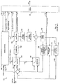
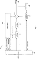
- the video encoder 100 of Figure 1 employs a combination of INTRA- and INTER-coding to produce a compressed (encoded) video bit-stream and decoder 200 of Figure 2 is arranged to receive and decode the video bit-stream produced by encoder 100 in order to produce a reconstructed video sequence.
- the luminance component of a macroblock comprises 16x16 pixels arranged as an array of 4, 8x8 blocks, and that the associated chrominance components are spatially sub-sampled by a factor of two in the horizontal and vertical directions to form 8x8 blocks, as depicted in Figure 3 .
- Extension of the description to other block sizes and other sub-sampling schemes will be apparent to those of ordinary skill in the art.
- the video encoder 100 comprises an input 101 for receiving a digital video signal from a camera or other video source (not shown). It also comprises a transformation unit 104 which is arranged to perform a block-based discrete cosine transform (DCT), a quantizer 106 , an inverse quantizer 108 , an inverse transformation unit 110 , arranged to perform an inverse block-based discrete cosine transform (IDCT), combiners 112 and 116 , and a frame store 120 .
- the encoder further comprises a motion estimator 130 , a motion field coder 140 and a motion compensated predictor 150 .
- Switches 102 and 114 are operated co-operatively by control manager 160 to switch the encoder between an INTRA-mode of video encoding and an INTER-mode of video encoding.
- the encoder 100 also comprises a video multiplex coder 170 which forms a single bit-stream from the various types of information produced by the encoder 100 for further transmission to a remote receiving terminal or, for example, for storage on a mass storage medium, such as a computer hard drive (not shown).
- Encoder 100 operates as follows. Each frame of uncompressed video provided from the video source to input 101 is received and processed macroblock by macroblock, preferably in raster-scan order. When the encoding of a new video sequence starts, the first frame to be encoded is encoded as an INTRA-coded frame.
- the encoder is programmed to code each frame in INTER-coded format, unless one of the following conditions is met: 1) it is judged that the current macroblock of the frame being coded is so dissimilar from the pixel values in the reference frame used in its prediction that excessive prediction error information is produced, in which case the current macroblock is coded in INTRA-coded format; 2) a predefined INTRA frame repetition interval has expired; or 3) feedback is received from a receiving terminal indicating a request for a frame to be provided in INTRA-coded format.
- the occurrence of condition 1) is detected by monitoring the output of the combiner 116 .
- the combiner 116 forms a difference between the current macroblock of the frame being coded and its prediction, produced in the motion compensated prediction block 150 . If a measure of this difference (for example a sum of absolute differences of pixel values) exceeds a predetermined threshold, the combiner 116 informs the control manager 160 via a control line 119 and the control manager 160 operates the switches 102 and 114 via control line 113 so as to switch the encoder 100 into INTRA-coding mode.
- a frame which is otherwise encoded in INTER-coded format may comprise INTRA-coded macroblocks.
- Occurrence of condition 2) is monitored by means of a timer or frame counter implemented in the control manager 160 , in such a way that if the timer expires, or the frame counter reaches a predetermined number of frames, the control manager 160 operates the switches 102 and 114 via control line 113 to switch the encoder into INTRA-coding mode.
- Condition 3) is triggered if the control manager 160 receives a feedback signal from, for example, a receiving terminal, via control line 121 indicating that an INTRA frame refresh is required by the receiving terminal.
- a condition may arise, for example, if a previously transmitted frame is badly corrupted by interference during its transmission, rendering it impossible to decode at the receiver. In this situation, the receiving decoder issues a request for the next frame to be encoded in INTRA-coded format, thus re-initialising the coding sequence.
- the control manager 160 operates the switch 102 to accept video input from input line 118 .
- the video signal input is received macroblock by macroblock from input 101 via the input line 118 .
- the blocks of luminance and chrominance values which make up the macroblock are passed to the DCT transformation block 104 , which performs a 2-dimensional discrete cosine transform on each block of values, producing a 2-dimensional array of DCT coefficients for each block.
- DCT transformation block 104 produces an array of coefficient values for each block, the number of coefficient values corresponding to the dimensions of the blocks which make up the macroblock (in this case 8x8).
- the DCT coefficients for each block are passed to the quantizer 106 , where they are quantized using a quantization parameter QP. Selection of the quantization parameter QP is controlled by the control manager 160 via control line 115 .
- the array of quantized DCT coefficients for each block is then passed from the quantizer 106 to the video multiplex coder 170 , as indicated by line 125 in Figure 1 .
- the video multiplex coder 170 orders the quantized transform coefficients for each block using a zigzag scanning procedure, thereby converting the two-dimensional array of quantized transform coefficients into a one-dimensional array.
- Each non-zero valued quantized coefficient in the one dimensional array is then represented as a pair of values, referred to as level and run, where level is the value of the quantized coefficient and run is the number of consecutive zero-valued coefficients preceding the coefficient in question.
- the run and level values are further compressed in the video multiplex coder 170 using entropy coding, for example, variable length coding (VLC), or arithmetic coding.
- VLC variable length coding
- the video multiplex coder 170 further combines them with control information, also entropy coded using a method appropriate for the kind of information in question, to form a single compressed bit-stream of coded image information 135 . It should be noted that while entropy coding has been described in connection with operations performed by the video multiplex coder 170 , in alternative implementations a separate entropy coding unit may be provided.
- a locally decoded version of the macroblock is also formed in the encoder 100 . This is done by passing the quantized transform coefficients for each block, output by quantizer 106 , through inverse quantizer 108 and applying an inverse DCT transform in inverse transformation block 110 . In this way a reconstructed array of pixel values is constructed for each block of the macroblock.
- the resulting decoded image data is input to combiner 112 .
- switch 114 is set so that the input to the combiner 112 via switch 114 is zero. In this way, the operation performed by combiner 112 is equivalent to passing the decoded image data unaltered.
- a decoded version of the INTRA-coded frame is built up in frame store 120 .
- the frame store 120 contains a completely decoded frame, available for use as a motion prediction reference frame in coding a subsequently received video frame in INTER-coded format.
- the control manager 160 operates switch 102 to receive its input from line 117 , which comprises the output of combiner 116 .
- the combiner 116 receives the video input signal macroblock by macroblock from input 101 .
- the prediction error information represents the difference between the block in question and its prediction, produced in motion compensated prediction block 150 .
- the prediction error information for each block of the macroblock comprises a two-dimensional array of values, each of which represents the difference between a pixel value in the block of luminance or chrominance information being coded and a decoded pixel value obtained by forming a motion-compensated prediction for the block, according to the procedure to be described below.
- each macroblock comprises, for example, an assembly of 8x8 blocks comprising luminance and chrominance values
- the prediction error information for each block of the macroblock similarly comprises an 8x8 array of prediction error values.
- the prediction error information for each block of the macroblock is passed to DCT transformation block 104 , which performs a two-dimensional discrete cosine transform on each block of prediction error values to produce a two-dimensional array of DCT transform coefficients for each block.
- DCT transformation block 104 produces an array of coefficient values for each prediction error block, the number of coefficient values corresponding to the dimensions of the blocks which make up the macroblock (in this case 8x8).
- the transform coefficients derived from each prediction error block are passed to quantizer 106 where they are quantized using a quantization parameter QP, in a manner analogous to that described above in connection with operation of the encoder in INTRA-coding mode. As before, selection of the quantization parameter QP is controlled by the control manager 160 via control line 115 .
- the quantized DCT coefficients representing the prediction error information for each block of the macroblock are passed from quantizer 106 to video multiplex coder 170 , as indicated by line 125 in Figure 1 .
- the video multiplex coder 170 orders the transform coefficients for each prediction error block using a certain zigzag scanning procedure and then represents each non-zero valued quantized coefficient as a run-level pair. It further compresses the run-level pairs using entropy coding, in a manner analogous to that described above in connection with INTRA-coding mode.
- Video multiplex coder 170 also receives motion vector information (described in the following) from motion field coding block 140 via line 126 and control information from control manager 160 . It entropy codes the motion vector information and control information and forms a single bit-stream of coded image information, 135 comprising the entropy coded motion vector, prediction error and control information.
- the quantized DCT coefficients representing the prediction error information for each block of the macroblock are also passed from quantizer 106 to inverse quantizer 108 . Here they are inverse quantized and the resulting blocks of inverse quantized DCT coefficients are applied to inverse DCT transform block 110 , where they undergo inverse DCT transformation to produce locally decoded blocks of prediction error values.
- the locally decoded blocks of prediction error values are then input to combiner 112 .
- switch 114 is set so that the combiner 112 also receives predicted pixel values for each block of the macroblock, generated by motion-compensated prediction block 150 .
- the combiner 112 combines each of the locally decoded blocks of prediction error values with a corresponding block of predicted pixel values to produce reconstructed image blocks and stores them in frame store 120 .
- a decoded version of the frame is built up in frame store 120 .
- the frame store 120 contains a completely decoded frame, available for use as a motion prediction reference frame in encoding a subsequently received video frame in INTER-coded format.
- any frame encoded in INTER-coded format requires a reference frame for motion-compensated prediction.
- the reference frame is formed by locally decoding either an INTRA-coded frame or an INTER-coded frame.
- a macroblock is the smallest element of a video frame that can be associated with motion information. It will further be assumed that a prediction for a given macroblock is formed by identifying a region of 16x16 values in the luminance component of the reference frame that shows best correspondence with the 16x16 luminance values of the macroblock in question. Motion-compensated prediction in a video coding system where motion information may be associated with elements smaller than a macroblock will be considered later in the text.
- the first step in forming a prediction for a macroblock of the current frame is performed by motion estimation block 130 .
- the motion estimation block 130 receives the blocks of luminance and chrominance values which make up the current macroblock of the frame to be coded via line 128 . It then performs a block matching operation in order to identify a region in the reference frame that corresponds best with the current macroblock.
- motion estimation block 130 accesses reference frame data stored in frame store 120 via line 127 . More specifically, motion estimation block 130 performs block-matching by calculating difference values (e.g. sums of absolute differences) representing the difference in pixel values between the macroblock under examination and candidate best-matching regions of pixels from a reference frame stored in the frame store 120 .
- difference values e.g. sums of absolute differences
- a difference value is produced for candidate regions at all possible offsets within a predefined search region of the reference frame and motion estimation block 130 determines the smallest calculated difference value.
- the candidate region that yields the smallest difference value is selected as the best-matching region.
- the offset between the current macroblock and the best-matching region identified in the reference frame defines a "motion vector" for the macroblock in question.
- the motion vector typically comprises a pair of numbers, one describing the horizontal ( ⁇ x) between the current macroblock and the best-matching region of the reference frame, the other representing the vertical displacement ( ⁇ y).
- the motion estimation block 130 outputs the motion vector to the motion field coding block 140 .
- the motion field coding block 140 approximates the motion vector received from motion estimation block 130 using a motion model comprising a set of basis functions and motion coefficients. More specifically, the motion field coding block 140 represents the motion vector as a set of motion coefficient values which, when multiplied by the basis functions, form an approximation of the motion vector.
- a translational motion model having only two motion coefficients and basis functions is used, but motion models of greater complexity may also be used.
- motion compensated prediction block 150 receives the best-matching region of pixel values identified by motion estimation block 130 from frame store 120 . Using the approximate representation of the motion vector generated by motion field coding block 140 and the pixel values of the best-matching region of pixels from the reference frame, motion compensated prediction block 150 generates an array of predicted pixel values for each block of the current macroblock. Each block of predicted pixel values is passed to combiner 116 where the predicted pixel values are subtracted from the actual (input) pixel values in the corresponding block of the current macroblock. In this way a set of prediction error blocks for the macroblock is obtained.
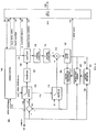
- the decoder 200 comprises a video multiplex decoder 270 , which receives an encoded video bit-stream 135 from the encoder 100 and demultiplexes it into its constituent parts, an inverse quantizer 210 , an inverse DCT transformer 220 , a motion compensated prediction block 240 , a frame store 250 , a combiner 230 , a control manager 260 , and an output 280 .
- the control manager 260 controls the operation of the decoder 200 in response to whether an INTRA- or an INTER-coded frame is being decoded.
- An INTRA / INTER trigger control signal which causes the decoder to switch between decoding modes is derived, for example, from picture type information associated with each compressed video frame received from the encoder.
- the INTRA / INTER trigger control signal is extracted from the encoded video bit-stream by the video multiplex decoder 270 and is passed to control manager 260 via control line 215 .
- Decoding of an INTRA-coded frame is performed on a macroblock-by-macroblock basis, each macroblock being decoded substantially as soon as encoded information relating to it is received in the video bit-stream 135 .
- the video multiplex decoder 270 separates the encoded information for the blocks of the macroblock from possible control information relating to the macroblock in question.
- the encoded information for each block of an INTRA-coded macroblock comprises variable length codewords representing the entropy coded level and run values for the non-zero quantized DCT coefficients of the block.
- the video multiplex decoder 270 decodes the variable length codewords using a variable length decoding method corresponding to the encoding method used in the encoder 100 and thereby recovers the level and run values.
- any control information relating to the macroblock is also decoded in the video multiplex decoder 270 using an appropriate decoding method and is passed to control manager 260 .
- information relating to the level of quantization applied to the transform coefficients is extracted from the encoded bit-stream by video multiplex decoder 270 and provided to control manager 260 via control line 217 .
- the control manager conveys this information to inverse quantizer 210 via control line 218 .
- Inverse quantizer 210 inverse quantizes the quantized DCT coefficients for each block of the macroblock according to the control information and provides the now inverse quantized DCT coefficients to inverse DCT transformer 220 .
- Inverse DCT transformer 220 performs an inverse DCT transform on the inverse quantized DCT coefficients for each block of the macroblock to form a decoded block of image information comprising reconstructed pixel values.
- the reconstructed pixel values for each block of the macroblock are passed via combiner 230 to the video output 280 of the decoder where, for example, they can be provided to a display device (not shown).
- the reconstructed pixel values for each block are also stored in frame store 250 . Because motion-compensated prediction is not used in the encoding/decoding of INTRA coded macroblocks control manager 260 controls combiner 230 to pass each block of pixel values as such to the video output 280 and frame store 250 .
- a decoded frame is progressively assembled in the frame store 250 and thus becomes available for use as a reference frame for motion compensated prediction in connection with the decoding of subsequently received INTER-coded frames.
- INTER-coded frames are also decoded macroblock by macroblock, each INTER-coded macroblock being decoded substantially as soon as encoded information relating to it is received in the bit-stream 135 .
- the video multiplex decoder 270 separates the encoded prediction error information for each block of an INTER-coded macroblock from encoded motion vector information and possible control information relating to the macroblock in question.
- the encoded prediction error information for each block of the macroblock comprises variable length codewords representing the entropy coded level and run values for the non-zero quantized transform coefficients of the prediction error block in question.
- the video multiplex decoder 270 decodes the variable length codewords using a variable length decoding method corresponding to the encoding method used in the encoder 100 and thereby recovers the level and run values. It then reconstructs an array of quantized transform coefficient values for each prediction error block and passes them to inverse quantizer 210 .
- Control information relating to the INTER-coded macroblock is also decoded in the video multiplex decoder 270 using an appropriate decoding method and is passed to control manager 260 .
- Information relating to the level of quantization applied to the transform coefficients of the prediction error blocks is extracted from the encoded bit-stream and provided to control manager 260 via control line 217 .
- the control manager conveys this information to inverse quantizer 210 via control line 218 .
- Inverse quantizer 210 inverse quantizes the quantized DCT coefficients representing the prediction error information for each block of the macroblock according to the control information and provides the now inverse quantized DCT coefficients to inverse DCT transformer 220 .
- the inverse quantized DCT coefficients representing the prediction error information for each block are then inverse transformed in the inverse DCT transformer 220 to yield an array of reconstructed prediction error values for each block of the macroblock.
- the encoded motion vector information associated with the macroblock is extracted from the encoded video bit-stream 135 by video multiplex decoder 270 and is decoded.
- the decoded motion vector information thus obtained is passed via control line 225 to motion compensated prediction block 240 , which reconstructs a motion vector for the macroblock using the same motion model as that used to encode the INTER-coded macroblock in encoder 100 .
- the reconstructed motion vector approximates the motion vector originally determined by motion estimation block 130 of the encoder.
- the motion compensated prediction block 240 of the decoder uses the reconstructed motion vector to identify the location of a region of reconstructed pixels in a prediction reference frame stored in frame store 250 .
- the reference frame may be, for example, a previously decoded INTRA-coded frame, or a previously decoded INTER-coded frame.
- the region of pixels indicated by the reconstructed motion vector is used to form a prediction for the macroblock in question.
- the motion compensated prediction block 240 forms an array of pixel values for each block of the macroblock by copying corresponding pixel values from the region of pixels identified by the motion vector.
- the prediction that is the blocks of pixel values derived from the reference frame, are passed from motion compensated prediction block 240 to combiner 230 where they are combined with the decoded prediction error information.
- the pixel values of each predicted block are added to corresponding reconstructed prediction error values output by inverse DCT transformer 220 .
- JVT Joint Video Team
- ISO/IEC MPEG Motion Pictures Expert Group
- ITU-T VCEG Video Coding Experts Group
- JM1 of the JVT codec video pictures are divided into macroblocks of 16x16 pixels and are coded on a macroblock-by-macroblock basis.
- the coding performed follows the basic principles described above in connection with the generic video encoder and decoder of Figures 1 and 2 .
- motion compensated prediction of INTER coded macroblocks is performed in manner that differs from that previously described. More specifically, each of the macroblocks is assigned a "coding mode" depending on the characteristics of the macroblock and the motion in the video sequence.
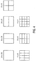
- Seven of the coding modes are based on dividing a macroblock to be INTER coded into a number of sub-blocks, each comprising NxM pixels, and associating motion information with each of the NxM sub-blocks, not just with the macroblock as a whole.
- Each of the possible schemes for dividing a macroblock into NxM sub-blocks, provided by JM1 of the JVT video codec, is illustrated in Figure 4 of the accompanying drawings. As can be seen from the figure, the possible divisions are: 16x16, 8x16, 16x8, 8x8, 4x8, 8x4 and 4x4.
- the macroblock is divided into two sub-blocks of size 16x8 pixels each and both sub-blocks is provided with its own motion information.
- an eighth coding mode known as SKIP (or skip) mode. If this mode is assigned to a macroblock, this indicates that the macroblock is to be copied from the reference video frame without using motion compensated prediction.
- the decision relating to the choice of coding mode for a given macroblock is typically made as part of the motion estimation process. More specifically, in a video encoder such as that illustrated in Figure 1 , but implemented to allow the use of different coding modes according to JM1 of the JVT codec, the motion estimation process performed by motion estimation block 130 is repeated for each possible division of the macroblock into NxM sub-blocks and for the skip mode.
- the motion estimation for the skip mode is a very simple one, since no motion search is needed, but a constant zero valued vector is assigned for this mode.
- the motion is typically estimated by performing a block matching operation for each motion block inside the macroblock. After these operations, the mode that minimizes a certain cost function is selected for the macroblock.
- the cost function typically combines the prediction error with number of estimated bits needed to code the macroblock and thus measures the relative efficiency of each coding mode.
- a video encoder operating in accordance with JM1 of the JVT codec assigns a particular coding mode to each macroblock that is INTER coded, it is necessary for a corresponding video decoder to be aware of that coding mode in order for it to correctly decode received information relating to the macroblock in question. Therefore, an indication of the coding mode assigned to each macroblock is provided in the video bit-stream transmitted from the video encoder to the video decoder. In order to minimise the amount of data required to indicate the coding modes, the coding mode for each macroblock is indicated using variable length coding.
- the codewords indicating the coding modes are assigned in such a way that the shortest codeword is used to represent the coding mode that is statistically most likely to occur.
- JM1 of the JVT codec uses a single set of so-called “Universal Variable Length Codes” (UVLC) to represent all syntax (data) elements in the video bit-stream and therefore this set of codewords is also used to represent the coding mode information for INTER coded macroblocks.
- the UVLC codewords used in JM1 may be written in the following compressed form, shown in Table 1 below, where the x n terms take either the value 0 or 1: Table 1: 1 0 x 0 1 0 X 1 0 x 0 1 0 x 2 0 x 1 0 x 0 1 x 3 0 x 2 0 x 1 0 x 0 1
- Table 2 presents the first 16 UVLC codewords, generated according to the scheme presented in Table 1.
- Table 2 Codeword Index UVLC Codeword 0 1 1 001 2 011 3 00001 4 00011 5 01001 6 01011 7 0000001 8 0000011 9 0001001 10 0001011 11 0100001 12 0100011 13 0101001 14 0101011 15 000000001 .... ....
- JM1 of the JVT codec assumes that the skip mode is statistically the most likely coding mode for a macroblock.
- the number of skip mode macroblocks before the next macroblock with non-SKIP mode is indicated by a single UVLC codeword using Table 2 above.
- the remaining coding modes are represented by UVLC codewords as shown in Table 3 below: Table 3: Macroblock Coding Modes of JM1 Codeword Index Mode UVLC Ccodeword - SKIP Run-Length Coded 0 16 x 16 1 1 16 x 8 001 2 8 x 16 011 3 8 x 8 00001 4 8 x 4 00011 5 4 x 8 01001 6 4 x 4 01011
- the NxM modes in the table above indicate the size of the motion blocks.
- This warped version of the reference frame may include alterations in the shape, size, and location with respect to the current picture.
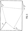
- the resampling process is defined in terms of a mapping between the four corners of the current picture and the corresponding four corners of the reference frame. Assuming that the luminance component of the current picture has a horizontal size H and vertical size V , the mapping is performed by defining four conceptual motion vectors v 00 , v H 0 , v 0 V , and v HV , each conceptual motion vector describing how to move one of the four corners of the current picture in such a way as to map it onto the corresponding corner of the reference frame. This operation is illustrated in Figure 5 .
- Motion compensated prediction for a macroblock of the current picture is then performed using block-matching with respect to the warped reference frame.
- This complicates the block matching process as the value of each pixel of the warped reference frame used in the block matching process must be generated by mapping pixel values in the original (non-warped) reference frame into the co-ordinates of the warped reference frame.
- the reader is referred to Annex P of the H.263 video coding standard for further details of the bilinear interpolation process used to generate the pixel values of the warped reference frame.
- Global motion vector coding as described in document VCEG-O20, referred to above, is a simplified version of global motion compensation.
- the reference frame is used as it is, but additional information is transmitted to describe the global motion and additional macroblock modes are used to indicate when global motion vectors are used.
- This approach is less complex than the global motion compensation technique just described, but there is additional encoder complexity associated with it. Namely, the encoder must perform extra motion estimation operations to find the global motion parameters and it also needs to evaluate more macroblock modes to find the optimal one. Moreover, the amount of extra global motion information that needs to be transmitted becomes large for small resolution video.
- JM1 of the JVT codec has no special provision for taking account of global motion in video sequences. Therefore, when such motion is present it causes the video encoder to select macroblock coding modes that explicitly model the motion. This leads to a significant degradation in coding efficiency, as the global motion component is encoded in every INTER coded macroblock (or sub-block).
- the technique of global motion compensation (as provided by Annex P of the H.263 video coding standard) takes global motion into account by warping reference frames used in motion compensated prediction and therefore provides improved coding efficiency compared with a system in which no special measures are taken to code global motion.
- the warping process is computationally complex and additional information must be transmitted in the encoded video bit-stream to enable correct decoding of the video sequence.
- the related technique of global motion vector coding is computationally less demanding than global motion compensation, it does involve a certain increase in encoder complexity and additional information must be still transmitted in the video bit-stream to enable correct decoding of the video data.
- the present invention is based on a redefinition of the skip mode concept used in JM1 of the JVT codec.
- the method according to the invention not only provides an improvement in coding efficiency in the presence of global motion (i.e. motion affecting the entire area of video frame), but also enables regional motion to be represented in an efficient manner.
- the skip mode concept is redefined in such a way that a macroblock assigned to skip mode is either associated with a zero (non-active) motion vector, in which case it is treated in the same way as a conventional skip mode macroblock and copied directly from the reference frame, or it is associated with a non-zero (active) motion vector.
- the decision as to whether a macroblock should be associated with a zero or non-zero motion vector is made by analysing the motion of other macroblocks or sub-blocks in a region surrounding the macroblock to be coded. If it is found that the surrounding region exhibits a certain type of motion, a non-zero motion vector representative of that motion is generated and associated with the current macroblock.
- the continuity, velocity or deviation of motion in the surrounding macroblocks or sub-blocks can be analyzed. For example, if the motion in the surrounding region exhibits a certain level of continuity, a certain common velocity, or a particular form of divergence, a motion vector representative of that motion can be assigned to the current macroblock to be coded. On the other hand, if the region surrounding the current macroblock does not exhibit such continuity, common velocity or divergence and has an insignificant level of motion, the macroblock to be coded is assigned a zero motion vector, causing it to be copied directly from the reference frame, just as if it were a conventional SKIP mode macroblock. In this way, according to the invention, SKIP mode macroblocks can adapt to the motion in the region surrounding them, enabling global or regional motion to taken account of in an efficient manner.
- the surrounding macroblocks or sub-blocks whose motion is analysed are previously encoded macroblocks neighboring the macroblock to be coded. This ensures that motion information relating to the region the surrounding a macroblock is available in the encoder (decoder) when a current macroblock is being encoded (decoded) and can be used directly to determine the motion vector to be assigned to the current macroblock.
- This approach enables the motion analysis of the surrounding region performed in the encoder to be duplicated exactly in the decoder. This, in turn, means that according to the invention, no additional information must be sent to the decoder in order to model global or regional motion.
- the method according to the invention enables global and regional motion within a video sequence to be taken account of in an efficient manner without the need for complex warping of the reference frame or any other computationally demanding operations.
- no additional information must be transmitted in the video bit-stream to enable correct decoding of the video data.
- a minimal amount of modification is required to incorporate the method according to the invention into existing video coding systems that employ the concept of skip mode macroblocks.
- a method of motion compensated prediction for use in encoding of a digital video sequence comprising a number of frames, said method comprising: assigning a coding mode to a segment of a first frame of the sequence to be encoded using motion compensated prediction with respect to a second frame of the sequence, said coding mode being one of a set of possible coding modes including a skip mode, wherein said skip mode, when assigned to said segment of the first frame, indicates either (i) that the segment has an insignificant level of motion, in which case, forming a prediction for the segment by copying directly from a corresponding region of the second frame, or (ii) that the segment has a motion characteristic of global or regional motion in the video sequence, in which case, forming a prediction for the segment by motion compensated prediction with respect to the second frame using motion information representative of said global or regional motion.
- the method comprises performing an analysis of motion in a region of the first frame surrounding the segment to be encoded in order to determine a characteristic of the motion in said region.
- said region of the first frame surrounding the segment to be encoded comprises previously encoded segments of the first frame.
- the skip mode is assigned as the coding mode of the segment and motion information indicative of zero motion is associated with the segment.
- the skip mode is assigned as the coding mode of the segment and motion information indicative of the global or regional motion in the surrounding region is associated with the segment.
- said analysis comprises examining said region of the first frame surrounding said segment to be encoded in order to identify at least one of the following types of motion: continuous motion, motion having a common velocity, and motion having a certain deviation.
- the skip mode is assigned as the coding mode of the segment and motion information indicative of zero motion is associated with the segment.
- a method of motion compensated prediction for use in decoding of an encoded digital video sequence comprising a number of frames, the method further comprising: receiving an indication of a coding mode assigned to a segment of a first frame of the sequence to be decoded using motion compensated prediction with respect to a second frame of the sequence, said coding mode being one of a set of possible coding modes including a skip mode; and determining, when said skip mode is indicated as the coding mode assigned to said segment of the first frame, (i) whether said skip mode indicates that the segment has an insignificant level of motion, in which case, motion compensated prediction for the segment is performed by copying directly from a corresponding region of the second frame, or (ii) whether said skip mode indicates that the segment has motion characteristic of global or regional motion in the video sequence, in which case motion compensated prediction for the segment is performed with respect to the second frame using motion information representative of said global or regional motion.
- said determining comprises: performing an analysis of motion in a previously decoded region of the first frame surrounding the segment to be decoded in order to determine a characteristic of the motion in said region.
- said analysis comprises examining the previously decoded region of the first frame surrounding said segment to be decoded in order to identify at least one of the following types of motion: continuous motion, motion having a common velocity, and motion having a certain deviation, wherein, if said at least one type of motion is identified in said surrounding region, it is determined that the skip mode indicates that the segment to be decoded has motion characteristic of global or regional motion in the video sequence.
- the skip mode indicates that the segment to be decoded has an insignificant level of motion.
- a video encoder arranged to encode a digital video sequence using motion compensated prediction, said digital video sequence comprising a number of frames, said encoder comprising: means for assigning a coding mode to a segment of a first frame of the sequence to be encoded using motion compensated prediction with respect to a second frame of the sequence, wherein said coding mode is one of a set of possible modes including a skip mode; and means for forming a prediction for the segment, wherein said skip mode, when assigned to said segment of the first frame indicates either (i) that the segment has an insignificant level of motion, in which case, said forming means forms a prediction for the segment by copying directly from a corresponding region of the second frame, or (ii) that the segment has motion characteristic of global or regional motion in the video sequence, in which case, said forming means forms a prediction for the segment with respect to the second frame using motion information representative of said global or regional motion.
- the encoder comprises means for analyzing motion in a region of the first frame surrounding the segment to be encoded in order to determine a characteristic of the motion in said region.
- said analyzing means is arranged to analyze motion in previously encoded segments of the first frame.
- the encoder is arranged to assign the skip mode as the coding mode of the segment and to associate motion information indicative of zero motion with the segment to be encoded.
- the encoder is arranged to assign the skip mode as the coding mode of the segment and to associate motion information indicative of the global or regional motion in the surrounding region with the segment to be encoded.
- said analyzing means comprises means for identifying at least one of the following types of motion: continuous motion, motion having a common velocity, and motion having a certain deviation.
- the encoder is arranged to assign the skip mode as the coding mode of the segment and to associate motion information indicative of zero motion with the segment to be encoded.
- a video decoder arranged to decode an encoded digital video sequence using motion compensated prediction, said digital video sequence comprising a number of frames, said decoder comprising: means for receiving an indication of a coding mode assigned to a segment of a first frame of the sequence to be decoded using motion compensated prediction with respect to a second frame of the sequence, said coding mode being one of a set of possible coding modes including a skip mode; and means for forming a prediction for the segment, wherein when said skip mode is indicated as the coding mode assigned to said segment of the first frame, the decoder is arranged to determine (i) whether said skip mode indicates that the segment has an insignificant level of motion, in which case said forming means forming the prediction for the segment by copying directly from a corresponding region of the second frame, or (ii) whether said skip mode indicates that the segment has motion characteristic of global or regional motion in the video sequence, in which case said forming means forming the prediction for the segment by motion compensated prediction with respect to
- the decoder further comprises means for analyzing motion in a previously decoded region of the first frame surrounding the segment to be decoded in order to determine a characteristic of the motion in said region.
- the decoder is arranged to associate motion information indicative of zero motion with the segment to be decoded.
- the decoder is arranged to associate motion information indicative of the global or regional motion in the surrounding region with the segment to be decoded.
- said analyzing means comprises means for identifying at least one of the following types of motion: continuous motion, motion having a common velocity, motion having a certain deviation.
- the decoder is arranged to associate motion information indicative of zero motion with the segment to be decoded.
- a multimedia terminal comprising means for obtaining a digital video sequence; and a video encoder arranged to encode the digital video sequence using motion compensated prediction, said digital video sequence comprising a number of frames
- the video encoder comprises: means for assigning a coding mode to a segment of a first frame of the sequence to be encoded using motion compensated prediction with respect to a second frame of the sequence, wherein said coding mode is one of a set of possible modes including a skip mode; and means for forming a prediction for the segment, wherein said skip mode, when assigned to said segment of the first frame, indicates either (i) that the segment has an insignificant level of motion, in which case, the video encoder is arranged such that said forming means forms a prediction for the segment by copying directly from a corresponding region of the second frame, or (ii) that the segment has motion characteristic of global or regional motion in the video sequence, in which case, the video encoder is arranged such that said forming means forms a prediction for the segment
- a multimedia terminal comprising: means for acquiring an encoded digital video sequence; and a video decoder arranged to decode the encoded digital video sequence using motion compensated prediction, said digital video sequence comprising a number of frames
- the video decoder comprises: means for receiving an indication of a coding mode assigned to a segment of a first frame of the sequence to be decoded using motion compensated prediction with respect to a second frame of the sequence, said coding mode being one of a set of possible coding modes including a skip mode; and means for forming a prediction for the segment, wherein when said skip mode is indicated as the coding mode assigned to said segment of the first frame, the decoder is arranged to determine (i) whether said skip mode indicates that the segment has an insignificant level of motion, in which case said forming means forming the prediction for the segment by copying directly from a corresponding region of the second frame, or (ii) whether said skip mode indicates that the segment has motion characteristic of global or regional motion in the video sequence,
- a video codec comprising: a video encoder arranged to encode a digital video sequence using motion compensated prediction, said digital video sequence comprising a number of frames, wherein the video encoder comprises: means for assigning a coding mode to a segment of a first frame of the sequence to be encoded using motion compensated prediction with respect to a second frame of the sequence, wherein said coding mode is one of a set of possible modes including a skip mode; and means for forming a prediction for the segment, wherein said skip mode, when assigned to said segment of the first frame, indicates either (i) that the segment has an insignificant level of motion, in which case, the video encoder is arranged such that said forming means forms a prediction for the segment by copying directly from a corresponding region of the second frame, or (ii) that the segment has motion characteristic of global or regional motion in the video sequence, in which case, the video encoder is arranged such that said forming means forms a prediction for the segment with respect to the second frame using motion
- skip (or SKIP) mode macroblocks in a video coding system adapt to the motion of surrounding image segments. If active motion is detected around a macroblock to be coded/decoded, motion parameters conforming to the motion are generated and the macroblock is motion compensated. In this way, no additional information needs to be transmitted from the encoder to the decoder.
- FIG. 6 is a schematic block diagram of a video encoder 600 implemented according to an embodiment of the invention.
- encoder 600 When encoding frames of a digital video sequence, encoder 600 operates in a manner similar to that previously described in connection with the prior art video encoder of Figure 1 to generate INTRA-coded and INTER-coded compressed video frames.
- the structure of the video encoder shown in Figure 6 is substantially identical to that of the prior art video encoder shown in Figure 1 , with appropriate modifications to the motion estimation part necessary to implement the video encoding method according to the invention. All parts of the video encoder which implement functions and operate in a manner identical to the previously described prior art video encoder are identified with identical reference numbers.
- the present invention relates to the encoding of video frames in INTER-coded format and more particularly to details of the motion-compensated prediction performed as part of the INTER coding process, description of encoder 600 in INTRA-coding mode will be omitted and the following sections will concentrate on the operations performed by the encoder in INTER-coding mode.
- the video encoder's control manager 160 operates switch 102 to receive its input from line 117 , which comprises the output of combiner 116 .
- the combiner 116 receives the video input signal macroblock by macroblock from input 101 .
- combiner 116 receives the blocks of luminance and chrominance values which make up the macroblock, it forms corresponding blocks of prediction error information, representing the difference between the block in question and its prediction, produced in motion compensated prediction block 650 .
- the prediction error information for each block of the macroblock is passed to DCT transformation block 104 , which performs a two-dimensional discrete cosine transform on each block of prediction error values to produce a two-dimensional array of DCT transform coefficients for each block. These are passed to quantizer 106 where they are quantized using a quantization parameter QP. Selection of the quantization parameter QP is controlled by the control manager 160 via control line 115 .
- the quantized DCT coefficients representing the prediction error information for each block of the macroblock are then passed from quantizer 106 to video multiplex coder 170 , via line 125 .
- the video multiplex coder 170 orders the transform coefficients for each prediction error block using a zigzag scanning procedure, represents each non-zero valued quantized coefficient as a run-level pair and compresses the run-level pairs using entropy coding.
- Video multiplex coder 170 also receives motion vector information from motion field coding block 640 via line 126 and control information from control manager 160 . It entropy codes the motion vector information and control information and forms a single bit-stream of coded image information, 135 comprising the entropy coded motion vector, prediction error and control information.
- the quantized DCT coefficients representing the prediction error information for each block of the macroblock are also passed from quantizer 106 to inverse quantizer 108 . Here they are inverse quantized and the resulting blocks of inverse quantized DCT coefficients are applied to inverse DCT transform block 110 , where they undergo inverse DCT transformation to produce locally decoded blocks of prediction error values.
- the locally decoded blocks of prediction error values are then input to combiner 112 .
- switch 114 is set so that the combiner 112 also receives predicted pixel values for each block of the macroblock, generated by motion-compensated prediction block 650 .
- the combiner 112 combines each of the locally decoded blocks of prediction error values with a corresponding block of predicted pixel values to produce reconstructed image blocks and stores them in frame store 120 .
- a decoded version of the frame is built up in frame store 120 .
- the frame store 120 contains a completely decoded frame, available for use as a motion prediction reference frame in encoding a subsequently received video frame in INTER-coded format.
- Encoder 600 performs motion-compensated prediction in a manner similar to the previously described JVT codec. In other words, it is adapted to assign a coding mode to each INTER-coded macroblock depending on the characteristics of the macroblock and the motion in the video sequence being coded.
- motion estimation block 630 performs a motion estimation operation for each coding mode in turn.
- Motion estimation block 630 receives the blocks of luminance and chrominance values which make up the macroblock to be coded for use in motion estimation via line 128 (see Figure 6 ).
- motion estimation block 630 selects that coding mode which yields the smallest overall cost value as the coding mode for the current macroblock.
- the coding modes used by encoder 600 correspond to those provided by JM1 of the JVT codec (shown in Table 3), with the exception that the SKIP mode is redefined to allow representation of global and regional motion. More specifically, the SKIP mode is modified in such a way that a zero (non-active) motion vector or a non-zero (active) motion vector is associated with each skip mode macroblock, depending on the characteristics of the motion in image segments surrounding the macroblock in question. In the following this type of motion vector will be referred to as a "skip mode motion vector".
- the encoder When examining skip mode as part of the previously described motion estimation process performed in turn for each coding mode, the encoder first determines whether a zero or a non-zero skip mode motion vector should be used. To do this, the encoder is arranged to analyze the motion of image segments (e.g. macroblocks and / or sub-blocks) surrounding the macroblock to be coded. If it determines that the surrounding region exhibits a certain type of motion, for example it has characteristics indicative of global or regional motion, it generates a non-zero valued skip mode motion vector representative of the motion. On the other hand, if the encoder determines that the region surrounding the current macroblock does not exhibit global or regional motion, but instead has an insignificant level of motion, it generates a zero valued skip mode motion vector.
- image segments e.g. macroblocks and / or sub-blocks
- skip mode coding is adapted to take account of this (by generating an associated non-zero valued skip mode motion vector representative of the motion).
- a zero valued motion vector is generated causing the skip mode as modified by the invention to operate in a conventional manner i.e. a zero valued skip mode motion vector causes a macroblock to be copied directly from the reference frame.
- encoder 600 determines which coding mode yields the smallest overall cost value and selects that mode as the coding mode for the macroblock in question.
- An indication of the finally selected coding mode for example a variable length codeword selected from the set of codewords presented in Table 3, is associated with the macroblock and included in the video bit-stream 635 . This enables a corresponding decoder to identify the coding mode for the macroblock and correctly reconstruct the macroblock using the correct form of motion-compensated prediction.
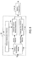
- Figure 8 illustrates the functional elements of the motion estimation block 630 associated with generating skip mode motion vectors. These include motion information memory 801 , surrounding motion analysis block 802 , active motion parameter generation block 803 and zero motion parameter generation block 804 .
- surrounding motion analysis block 802 The decision whether to generate a zero valued skip mode motion vector or a non-zero valued skip mode motion vector is made by surrounding motion analysis block 802 .
- the decision is made by analysing and classifying the motion of macroblocks or sub-blocks in a predefined region surrounding the macroblock to be coded using a predetermined analysis scheme.
- surrounding motion analysis block 802 retrieves motion information relating to the macroblocks and / or sub-blocks in the surrounding region from motion information memory 801 .
- surrounding motion analysis block may be arranged to analyze the continuity, velocity or deviation of motion in the surrounding macroblocks or sub-blocks.
- the surrounding motion analysis block determines that "active motion" is present in the surrounding region, it sends an indication to that effect to active motion parameter generation block 803 , which forms a non-zero valued skip mode motion vector representative of the motion in the surrounding region.
- active motion parameter generation block 803 retrieves motion information relating to the surrounding macroblocks and / or sub-blocks from motion information memory 801 . Alternatively, this information may be passed to the active motion parameter generation block by surrounding motion analysis block 802 . If surrounding motion analysis block determines that "non-active motion" is present in the surrounding region, it sends a corresponding indication to zero motion parameter generation block 804 , which forms a zero valued skip mode motion vector.
- the surrounding region of macroblocks or sub-blocks analyzed by the surrounding motion analysis block comprises previously encoded macroblocks neighboring the macroblock to be coded ( Figure 9 ).
- the analysis and classification of motion in the surrounding region performed in the encoder can be duplicated exactly in the decoder. This, in turn, means that according to the invention, no additional information must be sent to the decoder in order to model global or regional motion.
- the coding modes of already coded macroblocks are taken into account when deciding whether to use a zero valued or non-zero valued skip mode motion vector. For example, if the surrounding motion analysis block determines that there is one or more stationary neighboring macroblock, a zero valued skip mode motion vector is used.
- surrounding motion analysis block 802 classifies the motion in the region surrounding the macroblock according to the following three step procedure. Firstly, surrounding motion analysis block retrieves motion information for the macroblocks or sub-blocks surrounding the macroblock to be coded (i.e. previously encoded macroblocks neighboring the macroblock to be coded, as shown in Figure 9 ) and generates a median motion vector prediction for the macroblock.
- the median motion vector prediction is formed, for example, in a manner analogous to that used in motion vector prediction according to JM1 of the JVT codec (see T. Weigland: "Joint Model Number 1", Doc. JVT-A003, Joint Video Team of ISO/IEC MPEG and ITU-T VCEG, Jan. 2002 ).
- surrounding motion analysis block 802 determines if any of the resulting motion vector components has an absolute value larger than a certain threshold value (for example half a pixel). If this condition is fulfilled, the motion is classified as "active motion”, otherwise it is classified as “non-active motion”. Finally, depending on the classification result, surrounding motion analysis block 802 , sends an indication to either the active motion parameter generation block 803 or the zero motion parameter generation block 804 to in order to generate the appropriate skip mode motion parameters.
- a certain threshold value for example half a pixel
- Implementation of the surrounding motion analysis block according to the first preferred embodiment of the invention is particularly advantageous for two reasons. Firstly, in a typical video codec, such as the JVT codec, a median predictor is used to predict motion vectors of square image blocks. According to the first preferred embodiment, this same predictor is used in the surrounding motion analysis block and active motion parameter generation block to analyze motion in the region surrounding a macroblock to be coded and to generate motion parameters for SKIP mode macroblocks. In this way the invention can be implemented with minimal effect on the total implementation complexity of the video codec.
- active motion parameter generation block 803 can simply pass the median motion parameters, already generated in the surrounding motion analysis block, to the motion compensation block. This also minimizes the implementation complexity, since there is no need to generate additional motion parameters.
- the surrounding motion analysis block analyses the motion in vicinity of the macroblock to be coded and classifies it as either "active motion” or "non-active motion".
- active motion the active motion parameter generation block is activated and in the case of "non-active motion” the zero motion parameter generation block is activated.
- classification to the "non-active motion” category takes place if either or both of the two conditions below are true, otherwise the motion is classified as "active motion”:
- FIG. 7 The structure of the video decoder illustrated in Figure 7 is substantially identical to that of the prior art video decoder shown in Figure 2 , with appropriate modifications to those parts of the decoder that perform motion estimation operations. All parts of the video decoder which implement functions and operate in a manner identical to the previously described prior art video decoder are identified with identical reference numbers. It is further assumed that the video decoder of Figure 7 corresponds to the encoder described in connection with Figure 6 and is therefore capable of receiving and decoding the bit-stream 635 transmitted by encoder 600 . Furthermore, as the present invention affects the decoding of video frames in INTER-coded format, description of the operations performed by decoder 700 in connection with the decoding of INTRA-coded frames will be omitted.
- INTER-coded frames are decoded macroblock by macroblock, each INTER-coded macroblock being decoded substantially as soon as encoded information relating to it is received in the bit-stream 635 .
- the compressed video data included in the bit-stream for an INTER-coded macroblock may comprise a combination of VLC encoded prediction error information for each block, motion vector information for the macroblock (or sub-blocks) and encoded control information including an indication of the coding mode used to encode the macroblock in question. If a macroblock is encoded in skip mode, no prediction error or motion vector information relating to the macroblock is included in the bit-stream.
- Video multiplex decoder 270 receives the video bit-stream 635 and separates control information, including an indication of the coding mode of the macroblock from any encoded prediction error and / or motion vector information that may be present.
- prediction error information is encoded as variable length codewords representative of entropy coded level and run values. If prediction error information is provided for the current macroblock, the video multiplex decoder 270 recovers the level and run values by decoding the variable length codewords using a variable length decoding method corresponding to the encoding method used in encoder 600 . It then reconstructs an array of quantized DCT transform coefficient values for each prediction error block and passes them to inverse quantizer 210 where they are inverse quantized. The inverse quantized DCT coefficients are then inverse transformed in the inverse DCT transformer 220 to yield an array of reconstructed prediction error values for each block of the macroblock.
- Both the coding mode indication and encoded motion vector information (if any) associated with the macroblock are decoded in the video multiplex decoder and are passed via control line 225 to motion compensated prediction block 740 .
- Motion compensated prediction block 740 uses the coding mode indication and motion vector information (if any) to form a prediction for the macroblock in question. More specifically, the motion compensated prediction block 740 forms an array of pixel values for each block of the macroblock by copying corresponding pixel values from a region (or regions) of pixels in a reference frame.
- the prediction that is the blocks of pixel values derived from the reference frame, are passed from motion compensated prediction block 740 to combiner 230 where they are combined with the decoded prediction error information (if any). In this way an array of reconstructed pixel values for each block of the macroblock is obtained.
- the reconstructed pixel values are passed to the video output 280 of the decoder and are also stored in frame store 250 . Consequently, as subsequent macroblocks of the INTER-coded frame are decoded and stored, a decoded frame is progressively assembled in the frame store 250 and thus becomes available for use as a reference frame for motion-compensated prediction of other INTER-coded frames.
- the motion compensated prediction block 740 of decoder 700 comprises a motion information memory block 801 , a surrounding motion analysis block 802, an active motion parameter generation block 803 and a zero motion parameter generation block 804 analogous to those provided in encoder 600 .
- These functional blocks are used to determine whether a macroblock encoded in skip mode should be associated with a zero valued or a non-zero valued skip mode motion vector. More specifically, when it is determined that a macroblock to be decoded was encoded in skip mode, surrounding motion analysis block 802 analyses and classifies the motion of previously decoded macroblocks and / or sub-blocks in a predefined region surrounding the macroblock to be decoded in a manner exactly corresponding to that used in encoder 600 .
- the macroblock in question is either associated with a non-zero valued skip mode motion vector or a zero valued skip mode motion vector. This motion vector is then used to form a prediction for the macroblock. If the macroblock is associated with a zero valued skip mode motion vector, it is reconstructed by simply copying pixel values from a corresponding location in the reference frame. If, on the other hand, it is associated with a non-zero valued motion vector, a region of pixel values indicated by the non-zero motion vector is used to generate the pixel values for the macroblock.
- FIG. 10 of the accompanying drawings illustrates a multimedia terminal 80 implemented according to ITU-T recommendation H.324.
- the terminal can be regarded as a multimedia transceiver device. It includes elements that capture, encode and multiplex multimedia data streams for transmission via a communications network, as well as elements that receive, de-multiplex, decode and display received multimedia content.
- ITU-T recommendation H.324 defines the overall operation of the terminal and refers to other recommendations that govern the operation of its various constituent parts.
- This kind of multimedia terminal can be used in real-time applications such as conversational videotelephony, or non real-time applications such as the retrieval and / or streaming of video clips, for example from a multimedia content server in the Internet.
- the H.324 terminal shown in Figure 10 is only one of a number of alternative multimedia terminal implementations suited to application of the inventive method. It should also be noted that a number of alternatives exist relating to the location and implementation of the terminal equipment.
- the multimedia terminal may be located in communications equipment connected to a fixed line telephone network such as an analogue PSTN (Public Switched Telephone Network).
- PSTN Public Switched Telephone Network
- the multimedia terminal is equipped with a modem 91 , compliant with ITU-T recommendations V.8, V.34 and optionally V.8bis.
- the multimedia terminal may be connected to an external modem.
- the modem enables conversion of the multiplexed digital data and control signals produced by the multimedia terminal into an analogue form suitable for transmission over the PSTN. It further enables the multimedia terminal to receive data and control signals in analogue form from the PSTN and to convert them into a digital data stream that can be demultiplexed and processed in an appropriate manner by the terminal.
- An H.324 multimedia terminal may also be implemented in such a way that it can be connected directly to a digital fixed line network, such as an ISDN (Integrated Services Digital Network).
- a digital fixed line network such as an ISDN (Integrated Services Digital Network).
- the modem 91 is replaced with an ISDN user-network interface.
- this ISDN user-network interface is represented by alternative block 92.
- H.324 multimedia terminals may also be adapted for use in mobile communication applications. If used with a wireless communication link, the modem 91 can be replaced with any appropriate wireless interface, as represented by alternative block 93 in Figure 10 .
- an H.324/M multimedia terminal can include a radio transceiver enabling connection to the current 2 nd generation GSM mobile telephone network, or the proposed 3 rd generation UMTS (Universal Mobile Telephone System).
- a typical H.324 multimedia terminal will now be described in further detail with reference to Figure 10 .
- the multimedia terminal 80 includes a variety of elements referred to as "terminal equipment”. This includes video, audio and telematic devices, denoted generically by reference numbers 81,82 and 83 , respectively.
- the video equipment 81 may include, for example, a video camera for capturing video images, a monitor for displaying received video content and optional video processing equipment.
- the audio equipment 82 typically includes a microphone, for example for capturing spoken messages, and a loudspeaker for reproducing received audio content.
- the audio equipment may also include additional audio processing units.
- the telematic equipment 83 may include a data terminal, keyboard, electronic whiteboard or a still image transceiver, such as a fax unit.
- the video equipment 81 is coupled to a video codec 85 .
- the video codec 85 comprises a video encoder and a corresponding video decoder, both implemented according to the invention. Such an encoder and a decoder will be described in the following.
- the video codec 85 is responsible for encoding captured video data in an appropriate form for further transmission over a communications link and decoding compressed video content received from the communications network.
- the video codec is implemented according to JM1 of the JVT codec, with appropriate modifications to implement the modified SKIP mode concept according to the invention in both the encoder and the decoder of the video codec.
- the terminal's audio equipment is coupled to an audio codec, denoted in Figure 10 by reference number 86 .
- the audio codec comprises an encoder/decoder pair. It converts audio data captured by the terminal's audio equipment into a form suitable for transmission over the communications link and transforms encoded audio data received from the network back into a form suitable for reproduction, for example on the terminal's loudspeaker.
- the output of the audio codec is passed to a delay block 87 . This compensates for the delays introduced by the video coding process and thus ensures synchronisation of audio and video content.
- the system control block 84 of the multimedia terminal controls end-to-network signalling using an appropriate control protocol (signalling block 88 ) to establish a common mode of operation between a transmitting and a receiving terminal.
- the signalling block 88 exchanges information about the encoding and decoding capabilities of the transmitting and receiving terminals and can be used to enable the various coding modes of the video encoder.
- the system control block 84 also controls the use of data encryption. Information regarding the type of encryption to be used in data transmission is passed from encryption block 89 to the multiplexer/demultiplexer (MUX/DMUX unit) 90 .
- the MUX/DMUX unit 90 combines encoded and synchronised video and audio streams with data input from the telematic equipment 83 and possible control data, to form a single bit-stream.
- Information concerning the type of data encryption (if any) to be applied to the bit-stream, provided by encryption block 89 is used to select an encryption mode.
- MUX/DMUX unit 90 is responsible for decrypting the bit-stream, dividing it into its constituent multimedia components and passing those components to the appropriate codec(s) and/or terminal equipment for decoding and reproduction.
- the multimedia terminal 80 is a mobile terminal, that is, if it is equipped with a radio transceiver 93 , it will be understood by those skilled in the art that it may also comprise additional elements.
- it comprises a user interface having a display and a keyboard, which enables operation of the multimedia terminal 80 by a user, a central processing unit, such as a microprocessor, which controls the blocks responsible for different functions of the multimedia terminal, a random access memory RAM, a read only memory ROM, and a digital camera.
- the microprocessor's operating instructions that is program code corresponding to the basic functions of the multimedia terminal 80 , is stored in the read-only memory ROM and can be executed as required by the microprocessor, for example under control of the user.
- the microprocessor uses the radio transceiver 93 to form a connection with a mobile communication network, enabling the multimedia terminal 80 to transmit information to and receive information from the mobile communication network over a radio path.
- the microprocessor monitors the state of the user interface and controls the digital camera. In response to a user command, the microprocessor instructs the camera to record digital images into the RAM. Once an image or digital video sequence is captured, or alternatively during the capturing process, the microprocessor segments the image into image segments (for example macroblocks) and uses the encoder to perform motion compensated encoding of the segments in order to generate a compressed image sequence, as explained in the foregoing description.
- a user may command the multimedia terminal 80 to display the captured images on its display or to send the compressed video sequence using the radio transceiver 93 to another multimedia terminal, a video telephone connected to a fixed line network (PSTN) or some other telecommunications device.
- PSTN fixed line network
- transmission of image data is started as soon as the first segment is encoded so that the recipient can start a corresponding decoding process with a minimum delay.
- surrounding motion analysis block 802 is adapted to classify the motion of a surrounding region into more than two motion classes. For example, one meaningful classification involving three classes of motion would be “continuous motion", “active motion” and “non-active motion”. In this way special motion parameters for the typical case of continuous motion can be generated.
- the surrounding motion analysis block is removed and active motion parameter generation block is activated for all the skip mode macroblocks.
- the indication is provided by other means (for example as side information in macroblock, slice, picture or sequence levels).
- the surrounding motion analysis block may be temporarily disabled or enabled with such means.
- the macroblock mode table is rehashed depending on the output of the surrounding motion analysis block to give higher priority to more likely modes.
- the macroblock mode table is completely regenerated depending on the output of the surrounding motion analysis block, for example, by removing the skip.
- active motion parameters generation block 803 can be implemented in various ways. In particular embodiments of the invention it is adapted to generate the motion parameters, for example, based on the continuance, velocity or deviation of the surrounding motion. Additional side information can also be sent to guide the generation of motion parameters. In an alternative embodiment the active motion parameter generation block is adapted to output multiple motion vectors to be used in different parts of the macroblock.
- the invention can also be used to generate motion compensated prediction for other Macroblock modes in addition to or instead of the SKIP mode. It is also not limited by the macroblock structure but can be used in any segmentation based video coding system.
Landscapes
- Engineering & Computer Science (AREA)
- Multimedia (AREA)
- Signal Processing (AREA)
- Compression Or Coding Systems Of Tv Signals (AREA)
- Compression, Expansion, Code Conversion, And Decoders (AREA)
Applications Claiming Priority (2)
| Application Number | Priority Date | Filing Date | Title |
|---|---|---|---|
| US36507202P | 2002-03-15 | 2002-03-15 | |
| EP03744467.6A EP1486065B1 (fr) | 2002-03-15 | 2003-03-14 | Procede de codage du mouvement dans une sequence video |
Related Parent Applications (1)
| Application Number | Title | Priority Date | Filing Date |
|---|---|---|---|
| EP03744467.6A Division EP1486065B1 (fr) | 2002-03-15 | 2003-03-14 | Procede de codage du mouvement dans une sequence video |
Publications (1)
| Publication Number | Publication Date |
|---|---|
| EP3029938A1 true EP3029938A1 (fr) | 2016-06-08 |
Family
ID=28042010
Family Applications (2)
| Application Number | Title | Priority Date | Filing Date |
|---|---|---|---|
| EP16150129.1A Withdrawn EP3029938A1 (fr) | 2002-03-15 | 2003-03-14 | Procédé de codage du mouvement dans une séquence vidéo |
| EP03744467.6A Expired - Lifetime EP1486065B1 (fr) | 2002-03-15 | 2003-03-14 | Procede de codage du mouvement dans une sequence video |
Family Applications After (1)
| Application Number | Title | Priority Date | Filing Date |
|---|---|---|---|
| EP03744467.6A Expired - Lifetime EP1486065B1 (fr) | 2002-03-15 | 2003-03-14 | Procede de codage du mouvement dans une sequence video |
Country Status (16)
| Country | Link |
|---|---|
| US (1) | US7532808B2 (fr) |
| EP (2) | EP3029938A1 (fr) |
| JP (1) | JP4611640B2 (fr) |
| KR (2) | KR101108661B1 (fr) |
| CN (1) | CN100581232C (fr) |
| AU (1) | AU2003209566A1 (fr) |
| BR (2) | BRPI0304565B1 (fr) |
| CA (1) | CA2478691C (fr) |
| DK (1) | DK1486065T3 (fr) |
| ES (1) | ES2562932T3 (fr) |
| HK (1) | HK1079645A1 (fr) |
| HU (1) | HUE026930T2 (fr) |
| MX (1) | MXPA04008889A (fr) |
| PT (1) | PT1486065E (fr) |
| SI (1) | SI1486065T1 (fr) |
| WO (1) | WO2003079681A1 (fr) |
Families Citing this family (100)
| Publication number | Priority date | Publication date | Assignee | Title |
|---|---|---|---|---|
| US20030123738A1 (en) * | 2001-11-30 | 2003-07-03 | Per Frojdh | Global motion compensation for video pictures |
| JP3923898B2 (ja) * | 2002-01-18 | 2007-06-06 | 株式会社東芝 | 画像符号化方法及び装置 |
| US7742525B1 (en) * | 2002-07-14 | 2010-06-22 | Apple Inc. | Adaptive motion estimation |
| US7523482B2 (en) * | 2002-08-13 | 2009-04-21 | Microsoft Corporation | Seamless digital channel changing |
| US8397269B2 (en) | 2002-08-13 | 2013-03-12 | Microsoft Corporation | Fast digital channel changing |
| US7321623B2 (en) * | 2002-10-01 | 2008-01-22 | Avocent Corporation | Video compression system |
| US20060126718A1 (en) * | 2002-10-01 | 2006-06-15 | Avocent Corporation | Video compression encoder |
| US8824553B2 (en) | 2003-05-12 | 2014-09-02 | Google Inc. | Video compression method |
| US7603689B2 (en) * | 2003-06-13 | 2009-10-13 | Microsoft Corporation | Fast start-up for digital video streams |
| NO318318B1 (no) * | 2003-06-27 | 2005-02-28 | Tandberg Telecom As | Fremgangsmate for forbedret koding av video |
| US9560371B2 (en) | 2003-07-30 | 2017-01-31 | Avocent Corporation | Video compression system |
| US7444419B2 (en) * | 2003-10-10 | 2008-10-28 | Microsoft Corporation | Media stream scheduling for hiccup-free fast-channel-change in the presence of network chokepoints |
| US7562375B2 (en) | 2003-10-10 | 2009-07-14 | Microsoft Corporation | Fast channel change |
| US20050105621A1 (en) * | 2003-11-04 | 2005-05-19 | Ju Chi-Cheng | Apparatus capable of performing both block-matching motion compensation and global motion compensation and method thereof |
| KR20050053297A (ko) * | 2003-12-02 | 2005-06-08 | 학교법인 성균관대학 | 동영상 부호화 방법 및 장치 |
| US7430222B2 (en) * | 2004-02-27 | 2008-09-30 | Microsoft Corporation | Media stream splicer |
| US7720148B2 (en) * | 2004-03-26 | 2010-05-18 | The Hong Kong University Of Science And Technology | Efficient multi-frame motion estimation for video compression |
| KR100713400B1 (ko) * | 2004-04-30 | 2007-05-04 | 삼성전자주식회사 | 평균 히스토그램 오차 방식을 이용한 h.263/mpeg비디오 인코더 및 그 제어 방법 |
| US7457461B2 (en) | 2004-06-25 | 2008-11-25 | Avocent Corporation | Video compression noise immunity |
| US8111752B2 (en) * | 2004-06-27 | 2012-02-07 | Apple Inc. | Encoding mode pruning during video encoding |
| US20050286777A1 (en) * | 2004-06-27 | 2005-12-29 | Roger Kumar | Encoding and decoding images |
| US7792188B2 (en) | 2004-06-27 | 2010-09-07 | Apple Inc. | Selecting encoding types and predictive modes for encoding video data |
| DE102004038110B3 (de) * | 2004-08-05 | 2005-12-29 | Siemens Ag | Verfahren zum Codieren und Decodieren, sowie Codier- und Decodiervorrichtung zur Videocodierung |
| US8861601B2 (en) * | 2004-08-18 | 2014-10-14 | Qualcomm Incorporated | Encoder-assisted adaptive video frame interpolation |
| US7640352B2 (en) * | 2004-09-24 | 2009-12-29 | Microsoft Corporation | Methods and systems for presentation of media obtained from a media stream |
| DE102004049156B4 (de) * | 2004-10-08 | 2006-07-13 | Fraunhofer-Gesellschaft zur Förderung der angewandten Forschung e.V. | Codierschema für einen ein zeitlich veränderliches Graphikmodell darstellenden Datenstrom |
| FR2878383A1 (fr) * | 2004-11-19 | 2006-05-26 | France Telecom | Procede de codage predictif d'une sequence d'images, dispositif de codage, procede et dispositif de decodage et programme correspondants |
| US7477653B2 (en) * | 2004-12-10 | 2009-01-13 | Microsoft Corporation | Accelerated channel change in rate-limited environments |
| KR100681242B1 (ko) * | 2004-12-16 | 2007-02-09 | 삼성전자주식회사 | 동영상 복호화 방법, 동영상 복호화 장치 및 이를 가지는시스템 온 칩 시스템 |
| US8548055B2 (en) * | 2005-03-10 | 2013-10-01 | Qualcomm Incorporated | Encoding of multimedia data |
| EP2720466A1 (fr) * | 2005-09-26 | 2014-04-16 | Mitsubishi Electric Corporation | Procédé de codage d'image en mouvement |
| US20070110503A1 (en) * | 2005-10-31 | 2007-05-17 | Glover J S | Dispensing brush with replaceable cartridge/handle part |
| US8135040B2 (en) * | 2005-11-30 | 2012-03-13 | Microsoft Corporation | Accelerated channel change |
| US8718147B2 (en) * | 2006-02-17 | 2014-05-06 | Avocent Huntsville Corporation | Video compression algorithm |
| US7555570B2 (en) | 2006-02-17 | 2009-06-30 | Avocent Huntsville Corporation | Device and method for configuring a target device |
| WO2007105590A1 (fr) * | 2006-03-09 | 2007-09-20 | Nec Corporation | Procede de codage dynamique d'image et dispositif et programme l'utilisant |
| US20100091845A1 (en) * | 2006-03-30 | 2010-04-15 | Byeong Moon Jeon | Method and apparatus for decoding/encoding a video signal |
| KR100959538B1 (ko) * | 2006-03-30 | 2010-05-27 | 엘지전자 주식회사 | 비디오 신호를 디코딩/인코딩하기 위한 방법 및 장치 |
| US7782961B2 (en) * | 2006-04-28 | 2010-08-24 | Avocent Corporation | DVC delta commands |
| NO325859B1 (no) | 2006-05-31 | 2008-08-04 | Tandberg Telecom As | Kodek-preprosessering |
| WO2007148906A1 (fr) * | 2006-06-19 | 2007-12-27 | Lg Electronics, Inc. | Procédé et appareil de traitement d'un signal vidéo |
| US8532178B2 (en) * | 2006-08-25 | 2013-09-10 | Lg Electronics Inc. | Method and apparatus for decoding/encoding a video signal with inter-view reference picture list construction |
| JP4181592B2 (ja) * | 2006-09-20 | 2008-11-19 | シャープ株式会社 | 画像表示装置及び方法、画像処理装置及び方法 |
| US8804829B2 (en) * | 2006-12-20 | 2014-08-12 | Microsoft Corporation | Offline motion description for video generation |
| KR101136771B1 (ko) * | 2006-12-22 | 2012-04-20 | 퀄컴 인코포레이티드 | 다른 코딩 모드의 정보를 이용한 코딩 모드 선택 |
| US8311120B2 (en) * | 2006-12-22 | 2012-11-13 | Qualcomm Incorporated | Coding mode selection using information of other coding modes |
| JP5212742B2 (ja) * | 2007-02-20 | 2013-06-19 | ソニー株式会社 | 画像表示装置、映像信号処理装置および映像信号処理方法 |
| JP5040393B2 (ja) * | 2007-03-23 | 2012-10-03 | ソニー株式会社 | 画像処理装置および画像処理方法、プログラム、並びに画像表示装置 |
| KR101366241B1 (ko) | 2007-03-28 | 2014-02-21 | 삼성전자주식회사 | 영상 부호화, 복호화 방법 및 장치 |
| US20080240239A1 (en) * | 2007-04-02 | 2008-10-02 | Stuart David A | Methods and apparatus to selectively reduce streaming bandwidth consumption |
| JP4842899B2 (ja) * | 2007-08-15 | 2011-12-21 | Kddi株式会社 | 動画像符号化装置、動画像符号化方法およびプログラム |
| JP2009055519A (ja) * | 2007-08-29 | 2009-03-12 | Sony Corp | 符号化処理装置、符号化処理方法、復号処理装置、及び、復号処理方法 |
| US8938009B2 (en) * | 2007-10-12 | 2015-01-20 | Qualcomm Incorporated | Layered encoded bitstream structure |
| BRPI0818444A2 (pt) * | 2007-10-12 | 2016-10-11 | Qualcomm Inc | codificação adaptativa de informação de cabeçalho de bloco de vídeo |
| WO2009095962A1 (fr) * | 2008-01-29 | 2009-08-06 | Panasonic Corporation | Dispositif de codage d'image, procédé de codage d'image, circuit intégré de codage d'image et programme de codage d'image |
| US8385404B2 (en) * | 2008-09-11 | 2013-02-26 | Google Inc. | System and method for video encoding using constructed reference frame |
| US8325796B2 (en) | 2008-09-11 | 2012-12-04 | Google Inc. | System and method for video coding using adaptive segmentation |
| CN102210152A (zh) * | 2008-10-06 | 2011-10-05 | Lg电子株式会社 | 用于处理视频信号的方法和设备 |
| US9078592B2 (en) * | 2008-10-27 | 2015-07-14 | Wisconsin Alumni Research Foundation | Ultrasonic strain imaging device with selectable cost-function |
| KR101054644B1 (ko) * | 2008-11-25 | 2011-08-08 | 에스케이 텔레콤주식회사 | 동작 추정 기반 영상 부호화/복호화 장치 및 방법 |
| JP5325638B2 (ja) | 2008-11-26 | 2013-10-23 | 日立コンシューマエレクトロニクス株式会社 | 画像復号化方法 |
| US9124874B2 (en) * | 2009-06-05 | 2015-09-01 | Qualcomm Incorporated | Encoding of three-dimensional conversion information with two-dimensional video sequence |
| US9635368B2 (en) * | 2009-06-07 | 2017-04-25 | Lg Electronics Inc. | Method and apparatus for decoding a video signal |
| EP2446630B1 (fr) * | 2009-06-23 | 2020-02-26 | Orange | Codage et décodage d'une séquence d'images vidéo par zones d'image |
| US8526500B2 (en) * | 2009-08-11 | 2013-09-03 | Seiko Epson Corporation | System and method for global inter-frame motion detection in video sequences |
| KR101624649B1 (ko) * | 2009-08-14 | 2016-05-26 | 삼성전자주식회사 | 계층적인 부호화 블록 패턴 정보를 이용한 비디오 부호화 방법 및 장치, 비디오 복호화 방법 및 장치 |
| KR101356613B1 (ko) * | 2009-08-21 | 2014-02-06 | 에스케이텔레콤 주식회사 | 적응적 움직임 벡터 해상도를 이용한 영상 부호화/복호화 방법 및 장치 |
| WO2011021914A2 (fr) | 2009-08-21 | 2011-02-24 | 에스케이텔레콤 주식회사 | Procédé et appareil de codage/décodage d'images utilisant une résolution de vecteur de mouvement adaptative |
| WO2011074919A2 (fr) * | 2009-12-17 | 2011-06-23 | 에스케이텔레콤 주식회사 | Procédé et dispositif de codage/décodage d'image |
| KR20110069740A (ko) | 2009-12-17 | 2011-06-23 | 에스케이 텔레콤주식회사 | 영상 부호화/복호화 방법 및 장치 |
| US8879632B2 (en) * | 2010-02-18 | 2014-11-04 | Qualcomm Incorporated | Fixed point implementation for geometric motion partitioning |
| KR20110123651A (ko) * | 2010-05-07 | 2011-11-15 | 한국전자통신연구원 | 생략 부호화를 이용한 영상 부호화 및 복호화 장치 및 그 방법 |
| JP5805991B2 (ja) * | 2010-05-07 | 2015-11-10 | トムソン ライセンシングThomson Licensing | ピクチャ・シーケンスを符号化する方法、それに対応する再構築方法、および当該シーケンスを表す符号化データのストリーム |
| JP2013533469A (ja) | 2010-05-25 | 2013-08-22 | アリックス インク | 免疫診断における生物学的および化学的分析および用途における粒子の位置的自由度の検出のための方法および装置 |
| US20120057629A1 (en) | 2010-09-02 | 2012-03-08 | Fang Shi | Rho-domain Metrics |
| WO2012027893A1 (fr) * | 2010-09-02 | 2012-03-08 | Intersil Americas Inc. | Systèmes et procédés pour une analyse de contenu vidéo |
| US8503528B2 (en) | 2010-09-15 | 2013-08-06 | Google Inc. | System and method for encoding video using temporal filter |
| CN102447895B (zh) * | 2010-09-30 | 2013-10-02 | 华为技术有限公司 | 扫描方法及装置、反扫描方法及装置 |
| US9106916B1 (en) | 2010-10-29 | 2015-08-11 | Qualcomm Technologies, Inc. | Saturation insensitive H.264 weighted prediction coefficients estimation |
| US9172963B2 (en) * | 2010-11-01 | 2015-10-27 | Qualcomm Incorporated | Joint coding of syntax elements for video coding |
| US8638854B1 (en) | 2011-04-07 | 2014-01-28 | Google Inc. | Apparatus and method for creating an alternate reference frame for video compression using maximal differences |
| US9154799B2 (en) | 2011-04-07 | 2015-10-06 | Google Inc. | Encoding and decoding motion via image segmentation |
| US9509972B2 (en) * | 2011-06-24 | 2016-11-29 | Lg Electronics Inc. | Encoding/decoding method and apparatus using a skip mode |
| US20130083840A1 (en) * | 2011-09-30 | 2013-04-04 | Broadcom Corporation | Advance encode processing based on raw video data |
| US9432704B2 (en) * | 2011-11-06 | 2016-08-30 | Akamai Technologies Inc. | Segmented parallel encoding with frame-aware, variable-size chunking |
| US9262670B2 (en) | 2012-02-10 | 2016-02-16 | Google Inc. | Adaptive region of interest |
| WO2013162980A2 (fr) | 2012-04-23 | 2013-10-31 | Google Inc. | Gestion de tampons d'images à références multiples permettant un codage de données vidéo |
| US9609341B1 (en) | 2012-04-23 | 2017-03-28 | Google Inc. | Video data encoding and decoding using reference picture lists |
| CN102740073B (zh) * | 2012-05-30 | 2015-06-17 | 华为技术有限公司 | 一种编码方法及装置 |
| US9014266B1 (en) | 2012-06-05 | 2015-04-21 | Google Inc. | Decimated sliding windows for multi-reference prediction in video coding |
| US11317101B2 (en) * | 2012-06-12 | 2022-04-26 | Google Inc. | Inter frame candidate selection for a video encoder |
| CN104104964B (zh) * | 2013-04-09 | 2019-03-12 | 乐金电子(中国)研究开发中心有限公司 | 一种深度图像帧间编码、解码方法、编码器及解码器 |
| US9756331B1 (en) | 2013-06-17 | 2017-09-05 | Google Inc. | Advance coded reference prediction |
| FR3011429A1 (fr) * | 2013-09-27 | 2015-04-03 | Orange | Codage et decodage video par heritage d'un champ de vecteurs de mouvement |
| US9485456B2 (en) | 2013-12-30 | 2016-11-01 | Akamai Technologies, Inc. | Frame-rate conversion in a distributed computing system |
| US9392272B1 (en) | 2014-06-02 | 2016-07-12 | Google Inc. | Video coding using adaptive source variance based partitioning |
| US9578324B1 (en) | 2014-06-27 | 2017-02-21 | Google Inc. | Video coding using statistical-based spatially differentiated partitioning |
| WO2017087751A1 (fr) * | 2015-11-20 | 2017-05-26 | Mediatek Inc. | Procédé et appareil de compensation de mouvement global dans un système de codage vidéo |
| US10387099B2 (en) * | 2016-07-28 | 2019-08-20 | Intelligent Waves Llc | System, method and computer program product for generating remote views in a virtual mobile device platform using efficient color space conversion and frame encoding |
| CN112087626A (zh) * | 2020-08-21 | 2020-12-15 | 西安万像电子科技有限公司 | 图像处理方法、装置及存储介质 |
Citations (1)
| Publication number | Priority date | Publication date | Assignee | Title |
|---|---|---|---|---|
| US5719631A (en) * | 1995-11-07 | 1998-02-17 | Siemens Aktiengesellschaft | Method and apparatus for coding a video data stream of a video sequence formed of image blocks |
Family Cites Families (7)
| Publication number | Priority date | Publication date | Assignee | Title |
|---|---|---|---|---|
| JP2969782B2 (ja) | 1990-05-09 | 1999-11-02 | ソニー株式会社 | 符号化データ編集方法及び符号化データ編集装置 |
| US5148272A (en) | 1991-02-27 | 1992-09-15 | Rca Thomson Licensing Corporation | Apparatus for recombining prioritized video data |
| PT1098529E (pt) * | 1993-03-24 | 2013-11-25 | Sony Corp | Método para codificar e descodificar vetores de movimento e respetivo dispositivo e método para codificar e descodificar sinais de imagem e respetivo dispositivo |
| US5442400A (en) * | 1993-04-29 | 1995-08-15 | Rca Thomson Licensing Corporation | Error concealment apparatus for MPEG-like video data |
| JP3344577B2 (ja) * | 1996-09-09 | 2002-11-11 | ソニー株式会社 | 画像符号化装置および画像符号化方法、画像復号化装置および画像復号化方法、並びに記録方法 |
| JP2000278692A (ja) * | 1999-03-25 | 2000-10-06 | Victor Co Of Japan Ltd | 圧縮データ処理方法及び処理装置並びに記録再生システム |
| CN100452883C (zh) * | 2001-12-17 | 2009-01-14 | 微软公司 | 处理视频图像的方法 |
-
2003
- 2003-03-14 KR KR1020087026261A patent/KR101108661B1/ko active IP Right Grant
- 2003-03-14 WO PCT/IB2003/000944 patent/WO2003079681A1/fr active Application Filing
- 2003-03-14 CN CN03806139A patent/CN100581232C/zh not_active Expired - Lifetime
- 2003-03-14 JP JP2003577538A patent/JP4611640B2/ja not_active Expired - Lifetime
- 2003-03-14 PT PT37444676T patent/PT1486065E/pt unknown
- 2003-03-14 DK DK03744467.6T patent/DK1486065T3/en active
- 2003-03-14 AU AU2003209566A patent/AU2003209566A1/en not_active Abandoned
- 2003-03-14 SI SI200332467A patent/SI1486065T1/sl unknown
- 2003-03-14 BR BRPI0304565-0A patent/BRPI0304565B1/pt unknown
- 2003-03-14 EP EP16150129.1A patent/EP3029938A1/fr not_active Withdrawn
- 2003-03-14 KR KR1020047014524A patent/KR101108501B1/ko active IP Right Grant
- 2003-03-14 ES ES03744467.6T patent/ES2562932T3/es not_active Expired - Lifetime
- 2003-03-14 CA CA2478691A patent/CA2478691C/fr not_active Expired - Lifetime
- 2003-03-14 US US10/390,549 patent/US7532808B2/en active Active
- 2003-03-14 EP EP03744467.6A patent/EP1486065B1/fr not_active Expired - Lifetime
- 2003-03-14 HU HUE03744467A patent/HUE026930T2/en unknown
- 2003-03-14 BR BR0304565-0A patent/BR0304565A/pt active IP Right Grant
- 2003-03-14 MX MXPA04008889A patent/MXPA04008889A/es active IP Right Grant
-
2005
- 2005-12-15 HK HK05111555.9A patent/HK1079645A1/xx not_active IP Right Cessation
Patent Citations (1)
| Publication number | Priority date | Publication date | Assignee | Title |
|---|---|---|---|---|
| US5719631A (en) * | 1995-11-07 | 1998-02-17 | Siemens Aktiengesellschaft | Method and apparatus for coding a video data stream of a video sequence formed of image blocks |
Non-Patent Citations (12)
| Title |
|---|
| "Video Coding for Low Bit-Rate Communication", INTERNATIONAL TELECOMMUNICATIONS UNION ITU-T RECOMMENDATION H.263, February 1998 (1998-02-01) |
| KIMATA: "AHG Report: GMVC/GMC", 3. JVT MEETING; 60. MPEG MEETING; 06-05-2002 - 10-05-2002; FAIRFAX,US; (JOINT VIDEO TEAM OF ISO/IEC JTC1/SC29/WG11 AND ITU-T SG.16 ),, no. JVT-C011, 10 May 2002 (2002-05-10), XP030005119, ISSN: 0000-0442 * |
| KIMATA: "GMVC and GMC with B-picture", 3. JVT MEETING; 60. MPEG MEETING; 06-05-2002 - 10-05-2002; FAIRFAX,US; (JOINT VIDEO TEAM OF ISO/IEC JTC1/SC29/WG11 AND ITU-T SG.16 ),, no. JVT-C043, 10 May 2002 (2002-05-10), XP030005151, ISSN: 0000-0442 * |
| LAINEMA: "Skip mode motion compensation", 3. JVT MEETING; 60. MPEG MEETING; 06-05-2002 - 10-05-2002; FAIRFAX,US; (JOINT VIDEO TEAM OF ISO/IEC JTC1/SC29/WG11 AND ITU-T SG.16 ),, no. JVT-C027, 10 May 2002 (2002-05-10), XP030005133, ISSN: 0000-0442 * |
| SHIJUN SUN ET AL: "MOTION VECTOR CODING WITH GLOBAL MOTION PARAMETERS", ITU STUDY GROUP 16 - VIDEO CODING EXPERTS GROUP, XX, XX, no. VCEG-N16, 24 September 2001 (2001-09-24), pages 1 - 11, XP001152031 * |
| SHIJUN SUN; SHAWMIN LEI: "Global Motion Vector Coding", DOC. VCEG-020, ITU-T VIDEO CODING EXPERTS GROUP (VCEG) MEETING, PATTAYA, THAILAND, 4 December 2001 (2001-12-04) |
| SPECIALISTS GROUP ON CODING FOR VISUAL TELEPHONY ED - JOINT PHOTOGRAPHIC EXPERT GROUP (JPEG): "DESCRIPTION OF REF. MODEL 8 - RM8", JOINT PHOTOGRAPHIC EXPERT GROUP CONFERENCE, CROWBOROUGH : JPEG FORUM LTD, GB, 1 June 1989 (1989-06-01), XP017204674 * |
| SULLIVAN: "Report of Geneva Meeting (#2)", 2. JVT MEETING; 29-01-2002 - 01-02-2002; GENEVA, CH; (JOINT VIDEO TEAMOF ISO/IEC JTC1/SC29/WG11 AND ITU-T SG.16 ),, no. JVT-B001d5, 1 February 2002 (2002-02-01), XP030005005, ISSN: 0000-0443 * |
| SUN: "Additional zero-motion subblock for Motion Copy", 3. JVT MEETING; 60. MPEG MEETING; 06-05-2002 - 10-05-2002; FAIRFAX,US; (JOINT VIDEO TEAM OF ISO/IEC JTC1/SC29/WG11 AND ITU-T SG.16 ),, no. JVT-C022, 10 May 2002 (2002-05-10), XP030005128, ISSN: 0000-0442 * |
| T. WEIGLAND: "Joint Model Number 1", DOC. JVT-A003, JOINT VIDEO TEAM OF ISO/IEC MPEG AND ITU-T VCEG, January 2002 (2002-01-01) |
| T. WEIGLAND: "Joint Model Number 1", DOC. JVT-A003, JOINT VIDEO TEAM OF ISO/JEC MPEG AND ITU-T VCEG, January 2002 (2002-01-01) |
| WIEGAND: "Joint Model Number 1 (JM-1)", 1. JVT MEETING; 58. MPEG MEETING; 05-12-2001 - 06-12-2001; PATTAYA,TH; (JOINT VIDEO TEAM OF ISO/IEC JTC1/SC29/WG11 AND ITU-T SG.16 ),, no. JVT-A003, 6 December 2001 (2001-12-06), XP030005001, ISSN: 0000-0444 * |
Also Published As
| Publication number | Publication date |
|---|---|
| US7532808B2 (en) | 2009-05-12 |
| EP1486065A1 (fr) | 2004-12-15 |
| MXPA04008889A (es) | 2004-11-26 |
| KR20040091746A (ko) | 2004-10-28 |
| CN1643912A (zh) | 2005-07-20 |
| DK1486065T3 (en) | 2016-02-29 |
| EP1486065B1 (fr) | 2016-01-06 |
| BR0304565A (pt) | 2004-12-07 |
| CA2478691C (fr) | 2012-11-27 |
| BRPI0304565B1 (pt) | 2018-07-24 |
| JP2006500796A (ja) | 2006-01-05 |
| EP1486065A4 (fr) | 2006-01-04 |
| KR101108661B1 (ko) | 2012-01-25 |
| CA2478691A1 (fr) | 2003-09-25 |
| KR20080104385A (ko) | 2008-12-02 |
| KR101108501B1 (ko) | 2012-03-13 |
| WO2003079681A1 (fr) | 2003-09-25 |
| PT1486065E (pt) | 2016-03-30 |
| JP4611640B2 (ja) | 2011-01-12 |
| CN100581232C (zh) | 2010-01-13 |
| HUE026930T2 (en) | 2016-08-29 |
| US20030202594A1 (en) | 2003-10-30 |
| SI1486065T1 (sl) | 2016-05-31 |
| HK1079645A1 (en) | 2006-04-07 |
| ES2562932T3 (es) | 2016-03-09 |
| AU2003209566A1 (en) | 2003-09-29 |
Similar Documents
| Publication | Publication Date | Title |
|---|---|---|
| EP1486065B1 (fr) | Procede de codage du mouvement dans une sequence video | |
| US6690307B2 (en) | Adaptive variable length coding of digital video | |
| KR100953677B1 (ko) | 이미지/비디오 부호기들 및/또는 복호기들에서 변환계수들의 부호화 | |
| EP1497990B1 (fr) | Procede et dispositif d'indication de parametres d'un quantificateur dans un systeme de video codage | |
| EP1490975B1 (fr) | Coefficients de transformation de codage utilises dans des codeurs et/ou des decodeurs d'image/video | |
| EP1391121B1 (fr) | Codage a longueur variable |
Legal Events
| Date | Code | Title | Description |
|---|---|---|---|
| PUAI | Public reference made under article 153(3) epc to a published international application that has entered the european phase |
Free format text: ORIGINAL CODE: 0009012 |
|
| 17P | Request for examination filed |
Effective date: 20160105 |
|
| AC | Divisional application: reference to earlier application |
Ref document number: 1486065 Country of ref document: EP Kind code of ref document: P |
|
| AK | Designated contracting states |
Kind code of ref document: A1 Designated state(s): AT BE BG CH CY CZ DE DK EE ES FI FR GB GR HU IE IT LI LU MC NL PT RO SE SI SK TR |
|
| STAA | Information on the status of an ep patent application or granted ep patent |
Free format text: STATUS: REQUEST FOR EXAMINATION WAS MADE |
|
| RBV | Designated contracting states (corrected) |
Designated state(s): AT BE BG CH CY CZ DE DK EE ES FI FR GB GR HU IE IT LI LU MC NL PT RO SE SI SK TR |
|
| STAA | Information on the status of an ep patent application or granted ep patent |
Free format text: STATUS: EXAMINATION IS IN PROGRESS |
|
| 17Q | First examination report despatched |
Effective date: 20181010 |
|
| STAA | Information on the status of an ep patent application or granted ep patent |
Free format text: STATUS: EXAMINATION IS IN PROGRESS |
|
| RAP1 | Party data changed (applicant data changed or rights of an application transferred) |
Owner name: NOKIA TECHNOLOGIES OY |
|
| STAA | Information on the status of an ep patent application or granted ep patent |
Free format text: STATUS: EXAMINATION IS IN PROGRESS |
|
| STAA | Information on the status of an ep patent application or granted ep patent |
Free format text: STATUS: THE APPLICATION HAS BEEN WITHDRAWN |
|
| 18W | Application withdrawn |
Effective date: 20231221 |