EP3029741A1 - Photoelectric conversion device, method for manufacturing photoelectric conversion device, and electronic apparatus - Google Patents
Photoelectric conversion device, method for manufacturing photoelectric conversion device, and electronic apparatus Download PDFInfo
- Publication number
- EP3029741A1 EP3029741A1 EP15197736.0A EP15197736A EP3029741A1 EP 3029741 A1 EP3029741 A1 EP 3029741A1 EP 15197736 A EP15197736 A EP 15197736A EP 3029741 A1 EP3029741 A1 EP 3029741A1
- Authority
- EP
- European Patent Office
- Prior art keywords
- electrode
- film
- layer
- photoelectric conversion
- metal
- Prior art date
- Legal status (The legal status is an assumption and is not a legal conclusion. Google has not performed a legal analysis and makes no representation as to the accuracy of the status listed.)
- Granted
Links
- 238000006243 chemical reaction Methods 0.000 title claims abstract description 66
- 238000004519 manufacturing process Methods 0.000 title claims description 39
- 238000000034 method Methods 0.000 title claims description 28
- 239000004065 semiconductor Substances 0.000 claims abstract description 158
- 229910052751 metal Inorganic materials 0.000 claims abstract description 93
- 239000002184 metal Substances 0.000 claims abstract description 93
- 239000010410 layer Substances 0.000 claims description 354
- 229910044991 metal oxide Inorganic materials 0.000 claims description 69
- 150000004706 metal oxides Chemical class 0.000 claims description 69
- 239000000758 substrate Substances 0.000 claims description 51
- 239000002344 surface layer Substances 0.000 claims description 24
- DVRDHUBQLOKMHZ-UHFFFAOYSA-N chalcopyrite Chemical group [S-2].[S-2].[Fe+2].[Cu+2] DVRDHUBQLOKMHZ-UHFFFAOYSA-N 0.000 claims description 22
- 229910052795 boron group element Inorganic materials 0.000 claims description 16
- 150000003346 selenoethers Chemical class 0.000 claims description 8
- 238000000151 deposition Methods 0.000 claims description 6
- 239000010408 film Substances 0.000 description 332
- 238000010438 heat treatment Methods 0.000 description 29
- 239000011241 protective layer Substances 0.000 description 21
- 101000821827 Homo sapiens Sodium/nucleoside cotransporter 2 Proteins 0.000 description 18
- 102100021541 Sodium/nucleoside cotransporter 2 Human genes 0.000 description 18
- 101000685663 Homo sapiens Sodium/nucleoside cotransporter 1 Proteins 0.000 description 17
- 102100023116 Sodium/nucleoside cotransporter 1 Human genes 0.000 description 17
- 239000010949 copper Substances 0.000 description 14
- 238000010586 diagram Methods 0.000 description 14
- 230000003595 spectral effect Effects 0.000 description 14
- BUGBHKTXTAQXES-UHFFFAOYSA-N Selenium Chemical compound [Se] BUGBHKTXTAQXES-UHFFFAOYSA-N 0.000 description 12
- VYPSYNLAJGMNEJ-UHFFFAOYSA-N Silicium dioxide Chemical compound O=[Si]=O VYPSYNLAJGMNEJ-UHFFFAOYSA-N 0.000 description 12
- 229910052798 chalcogen Inorganic materials 0.000 description 12
- MHWZQNGIEIYAQJ-UHFFFAOYSA-N molybdenum diselenide Chemical compound [Se]=[Mo]=[Se] MHWZQNGIEIYAQJ-UHFFFAOYSA-N 0.000 description 12
- 101000822028 Homo sapiens Solute carrier family 28 member 3 Proteins 0.000 description 11
- 102100021470 Solute carrier family 28 member 3 Human genes 0.000 description 11
- 230000035945 sensitivity Effects 0.000 description 11
- 238000004544 sputter deposition Methods 0.000 description 10
- 230000001681 protective effect Effects 0.000 description 9
- XLOMVQKBTHCTTD-UHFFFAOYSA-N Zinc monoxide Chemical compound [Zn]=O XLOMVQKBTHCTTD-UHFFFAOYSA-N 0.000 description 8
- 230000002093 peripheral effect Effects 0.000 description 8
- 229910052814 silicon oxide Inorganic materials 0.000 description 8
- ZOKXTWBITQBERF-UHFFFAOYSA-N Molybdenum Chemical compound [Mo] ZOKXTWBITQBERF-UHFFFAOYSA-N 0.000 description 7
- 229910052581 Si3N4 Inorganic materials 0.000 description 7
- 210000004204 blood vessel Anatomy 0.000 description 7
- 229910052802 copper Inorganic materials 0.000 description 7
- 229910052750 molybdenum Inorganic materials 0.000 description 7
- 239000011733 molybdenum Substances 0.000 description 7
- 229910000058 selane Inorganic materials 0.000 description 7
- HQVNEWCFYHHQES-UHFFFAOYSA-N silicon nitride Chemical compound N12[Si]34N5[Si]62N3[Si]51N64 HQVNEWCFYHHQES-UHFFFAOYSA-N 0.000 description 7
- 206010034972 Photosensitivity reaction Diseases 0.000 description 6
- 238000004891 communication Methods 0.000 description 6
- 229910052738 indium Inorganic materials 0.000 description 6
- 239000011229 interlayer Substances 0.000 description 6
- 238000000059 patterning Methods 0.000 description 6
- 230000036211 photosensitivity Effects 0.000 description 6
- 239000011669 selenium Substances 0.000 description 6
- RYGMFSIKBFXOCR-UHFFFAOYSA-N Copper Chemical compound [Cu] RYGMFSIKBFXOCR-UHFFFAOYSA-N 0.000 description 5
- 229910004205 SiNX Inorganic materials 0.000 description 5
- 210000004369 blood Anatomy 0.000 description 5
- 239000008280 blood Substances 0.000 description 5
- 239000007789 gas Substances 0.000 description 5
- 238000003860 storage Methods 0.000 description 5
- 210000000707 wrist Anatomy 0.000 description 5
- 238000005530 etching Methods 0.000 description 4
- 229910052733 gallium Inorganic materials 0.000 description 4
- APFVFJFRJDLVQX-UHFFFAOYSA-N indium atom Chemical compound [In] APFVFJFRJDLVQX-UHFFFAOYSA-N 0.000 description 4
- 239000011787 zinc oxide Substances 0.000 description 4
- 238000005229 chemical vapour deposition Methods 0.000 description 3
- 230000004044 response Effects 0.000 description 3
- 229910052711 selenium Inorganic materials 0.000 description 3
- RWSOTUBLDIXVET-UHFFFAOYSA-N Dihydrogen sulfide Chemical compound S RWSOTUBLDIXVET-UHFFFAOYSA-N 0.000 description 2
- GYHNNYVSQQEPJS-UHFFFAOYSA-N Gallium Chemical compound [Ga] GYHNNYVSQQEPJS-UHFFFAOYSA-N 0.000 description 2
- NINIDFKCEFEMDL-UHFFFAOYSA-N Sulfur Chemical compound [S] NINIDFKCEFEMDL-UHFFFAOYSA-N 0.000 description 2
- QVGXLLKOCUKJST-UHFFFAOYSA-N atomic oxygen Chemical compound [O] QVGXLLKOCUKJST-UHFFFAOYSA-N 0.000 description 2
- 229910052800 carbon group element Inorganic materials 0.000 description 2
- 230000008859 change Effects 0.000 description 2
- 229910052681 coesite Inorganic materials 0.000 description 2
- 229910052906 cristobalite Inorganic materials 0.000 description 2
- QXYJCZRRLLQGCR-UHFFFAOYSA-N dioxomolybdenum Chemical compound O=[Mo]=O QXYJCZRRLLQGCR-UHFFFAOYSA-N 0.000 description 2
- 230000002349 favourable effect Effects 0.000 description 2
- 229910001849 group 12 element Inorganic materials 0.000 description 2
- JKQOBWVOAYFWKG-UHFFFAOYSA-N molybdenum trioxide Chemical compound O=[Mo](=O)=O JKQOBWVOAYFWKG-UHFFFAOYSA-N 0.000 description 2
- 239000010955 niobium Substances 0.000 description 2
- 229910052760 oxygen Inorganic materials 0.000 description 2
- 239000001301 oxygen Substances 0.000 description 2
- 230000000149 penetrating effect Effects 0.000 description 2
- 238000005240 physical vapour deposition Methods 0.000 description 2
- 239000000377 silicon dioxide Substances 0.000 description 2
- 229910052682 stishovite Inorganic materials 0.000 description 2
- 229910052717 sulfur Inorganic materials 0.000 description 2
- 239000011593 sulfur Substances 0.000 description 2
- 229910052905 tridymite Inorganic materials 0.000 description 2
- 210000003462 vein Anatomy 0.000 description 2
- 229910017612 Cu(In,Ga)Se2 Inorganic materials 0.000 description 1
- 229910002475 Cu2ZnSnS4 Inorganic materials 0.000 description 1
- WQZGKKKJIJFFOK-GASJEMHNSA-N Glucose Natural products OC[C@H]1OC(O)[C@H](O)[C@@H](O)[C@@H]1O WQZGKKKJIJFFOK-GASJEMHNSA-N 0.000 description 1
- 229910015711 MoOx Inorganic materials 0.000 description 1
- ATJFFYVFTNAWJD-UHFFFAOYSA-N Tin Chemical compound [Sn] ATJFFYVFTNAWJD-UHFFFAOYSA-N 0.000 description 1
- 229910045601 alloy Inorganic materials 0.000 description 1
- 239000000956 alloy Substances 0.000 description 1
- 229910052782 aluminium Inorganic materials 0.000 description 1
- XAGFODPZIPBFFR-UHFFFAOYSA-N aluminium Chemical compound [Al] XAGFODPZIPBFFR-UHFFFAOYSA-N 0.000 description 1
- 230000002238 attenuated effect Effects 0.000 description 1
- 230000008901 benefit Effects 0.000 description 1
- 210000005252 bulbus oculi Anatomy 0.000 description 1
- 239000003086 colorant Substances 0.000 description 1
- 239000006059 cover glass Substances 0.000 description 1
- 230000008021 deposition Effects 0.000 description 1
- 238000001514 detection method Methods 0.000 description 1
- 238000009826 distribution Methods 0.000 description 1
- 230000000694 effects Effects 0.000 description 1
- 238000005401 electroluminescence Methods 0.000 description 1
- 239000011521 glass Substances 0.000 description 1
- 239000008103 glucose Substances 0.000 description 1
- 229910000037 hydrogen sulfide Inorganic materials 0.000 description 1
- 238000003384 imaging method Methods 0.000 description 1
- AMGQUBHHOARCQH-UHFFFAOYSA-N indium;oxotin Chemical compound [In].[Sn]=O AMGQUBHHOARCQH-UHFFFAOYSA-N 0.000 description 1
- 239000011810 insulating material Substances 0.000 description 1
- 239000000463 material Substances 0.000 description 1
- 238000005259 measurement Methods 0.000 description 1
- 239000007769 metal material Substances 0.000 description 1
- 238000002156 mixing Methods 0.000 description 1
- 238000012986 modification Methods 0.000 description 1
- 230000004048 modification Effects 0.000 description 1
- 229910000476 molybdenum oxide Inorganic materials 0.000 description 1
- 229910052758 niobium Inorganic materials 0.000 description 1
- GUCVJGMIXFAOAE-UHFFFAOYSA-N niobium atom Chemical compound [Nb] GUCVJGMIXFAOAE-UHFFFAOYSA-N 0.000 description 1
- 230000003647 oxidation Effects 0.000 description 1
- 238000007254 oxidation reaction Methods 0.000 description 1
- 230000001590 oxidative effect Effects 0.000 description 1
- PQQKPALAQIIWST-UHFFFAOYSA-N oxomolybdenum Chemical compound [Mo]=O PQQKPALAQIIWST-UHFFFAOYSA-N 0.000 description 1
- 229910021420 polycrystalline silicon Inorganic materials 0.000 description 1
- 230000008569 process Effects 0.000 description 1
- 238000012545 processing Methods 0.000 description 1
- 229910052710 silicon Inorganic materials 0.000 description 1
- 239000010703 silicon Substances 0.000 description 1
- 229910052715 tantalum Inorganic materials 0.000 description 1
- GUVRBAGPIYLISA-UHFFFAOYSA-N tantalum atom Chemical compound [Ta] GUVRBAGPIYLISA-UHFFFAOYSA-N 0.000 description 1
- JBQYATWDVHIOAR-UHFFFAOYSA-N tellanylidenegermanium Chemical compound [Te]=[Ge] JBQYATWDVHIOAR-UHFFFAOYSA-N 0.000 description 1
- 229910052714 tellurium Inorganic materials 0.000 description 1
- PORWMNRCUJJQNO-UHFFFAOYSA-N tellurium atom Chemical compound [Te] PORWMNRCUJJQNO-UHFFFAOYSA-N 0.000 description 1
- 239000010409 thin film Substances 0.000 description 1
- WFKWXMTUELFFGS-UHFFFAOYSA-N tungsten Chemical compound [W] WFKWXMTUELFFGS-UHFFFAOYSA-N 0.000 description 1
- 229910052721 tungsten Inorganic materials 0.000 description 1
- 239000010937 tungsten Substances 0.000 description 1
- YVTHLONGBIQYBO-UHFFFAOYSA-N zinc indium(3+) oxygen(2-) Chemical compound [O--].[Zn++].[In+3] YVTHLONGBIQYBO-UHFFFAOYSA-N 0.000 description 1
Images


Classifications
-
- H—ELECTRICITY
- H01—ELECTRIC ELEMENTS
- H01L—SEMICONDUCTOR DEVICES NOT COVERED BY CLASS H10
- H01L27/00—Devices consisting of a plurality of semiconductor or other solid-state components formed in or on a common substrate
- H01L27/14—Devices consisting of a plurality of semiconductor or other solid-state components formed in or on a common substrate including semiconductor components sensitive to infrared radiation, light, electromagnetic radiation of shorter wavelength or corpuscular radiation and specially adapted either for the conversion of the energy of such radiation into electrical energy or for the control of electrical energy by such radiation
- H01L27/144—Devices controlled by radiation
- H01L27/146—Imager structures
- H01L27/14643—Photodiode arrays; MOS imagers
- H01L27/14649—Infrared imagers
-
- H—ELECTRICITY
- H01—ELECTRIC ELEMENTS
- H01L—SEMICONDUCTOR DEVICES NOT COVERED BY CLASS H10
- H01L25/00—Assemblies consisting of a plurality of individual semiconductor or other solid state devices ; Multistep manufacturing processes thereof
- H01L25/03—Assemblies consisting of a plurality of individual semiconductor or other solid state devices ; Multistep manufacturing processes thereof all the devices being of a type provided for in the same subgroup of groups H01L27/00 - H01L33/00, or in a single subclass of H10K, H10N, e.g. assemblies of rectifier diodes
- H01L25/04—Assemblies consisting of a plurality of individual semiconductor or other solid state devices ; Multistep manufacturing processes thereof all the devices being of a type provided for in the same subgroup of groups H01L27/00 - H01L33/00, or in a single subclass of H10K, H10N, e.g. assemblies of rectifier diodes the devices not having separate containers
- H01L25/041—Assemblies consisting of a plurality of individual semiconductor or other solid state devices ; Multistep manufacturing processes thereof all the devices being of a type provided for in the same subgroup of groups H01L27/00 - H01L33/00, or in a single subclass of H10K, H10N, e.g. assemblies of rectifier diodes the devices not having separate containers the devices being of a type provided for in group H01L31/00
- H01L25/043—Stacked arrangements of devices
-
- H—ELECTRICITY
- H01—ELECTRIC ELEMENTS
- H01L—SEMICONDUCTOR DEVICES NOT COVERED BY CLASS H10
- H01L27/00—Devices consisting of a plurality of semiconductor or other solid-state components formed in or on a common substrate
- H01L27/14—Devices consisting of a plurality of semiconductor or other solid-state components formed in or on a common substrate including semiconductor components sensitive to infrared radiation, light, electromagnetic radiation of shorter wavelength or corpuscular radiation and specially adapted either for the conversion of the energy of such radiation into electrical energy or for the control of electrical energy by such radiation
- H01L27/144—Devices controlled by radiation
- H01L27/146—Imager structures
- H01L27/14601—Structural or functional details thereof
- H01L27/1462—Coatings
- H01L27/14623—Optical shielding
-
- H—ELECTRICITY
- H01—ELECTRIC ELEMENTS
- H01L—SEMICONDUCTOR DEVICES NOT COVERED BY CLASS H10
- H01L27/00—Devices consisting of a plurality of semiconductor or other solid-state components formed in or on a common substrate
- H01L27/14—Devices consisting of a plurality of semiconductor or other solid-state components formed in or on a common substrate including semiconductor components sensitive to infrared radiation, light, electromagnetic radiation of shorter wavelength or corpuscular radiation and specially adapted either for the conversion of the energy of such radiation into electrical energy or for the control of electrical energy by such radiation
- H01L27/144—Devices controlled by radiation
- H01L27/146—Imager structures
- H01L27/14601—Structural or functional details thereof
- H01L27/14632—Wafer-level processed structures
-
- H—ELECTRICITY
- H01—ELECTRIC ELEMENTS
- H01L—SEMICONDUCTOR DEVICES NOT COVERED BY CLASS H10
- H01L27/00—Devices consisting of a plurality of semiconductor or other solid-state components formed in or on a common substrate
- H01L27/14—Devices consisting of a plurality of semiconductor or other solid-state components formed in or on a common substrate including semiconductor components sensitive to infrared radiation, light, electromagnetic radiation of shorter wavelength or corpuscular radiation and specially adapted either for the conversion of the energy of such radiation into electrical energy or for the control of electrical energy by such radiation
- H01L27/144—Devices controlled by radiation
- H01L27/146—Imager structures
- H01L27/14601—Structural or functional details thereof
- H01L27/14634—Assemblies, i.e. Hybrid structures
-
- H—ELECTRICITY
- H01—ELECTRIC ELEMENTS
- H01L—SEMICONDUCTOR DEVICES NOT COVERED BY CLASS H10
- H01L27/00—Devices consisting of a plurality of semiconductor or other solid-state components formed in or on a common substrate
- H01L27/14—Devices consisting of a plurality of semiconductor or other solid-state components formed in or on a common substrate including semiconductor components sensitive to infrared radiation, light, electromagnetic radiation of shorter wavelength or corpuscular radiation and specially adapted either for the conversion of the energy of such radiation into electrical energy or for the control of electrical energy by such radiation
- H01L27/144—Devices controlled by radiation
- H01L27/146—Imager structures
- H01L27/14683—Processes or apparatus peculiar to the manufacture or treatment of these devices or parts thereof
- H01L27/14687—Wafer level processing
-
- H—ELECTRICITY
- H01—ELECTRIC ELEMENTS
- H01L—SEMICONDUCTOR DEVICES NOT COVERED BY CLASS H10
- H01L27/00—Devices consisting of a plurality of semiconductor or other solid-state components formed in or on a common substrate
- H01L27/14—Devices consisting of a plurality of semiconductor or other solid-state components formed in or on a common substrate including semiconductor components sensitive to infrared radiation, light, electromagnetic radiation of shorter wavelength or corpuscular radiation and specially adapted either for the conversion of the energy of such radiation into electrical energy or for the control of electrical energy by such radiation
- H01L27/144—Devices controlled by radiation
- H01L27/146—Imager structures
- H01L27/14683—Processes or apparatus peculiar to the manufacture or treatment of these devices or parts thereof
- H01L27/14689—MOS based technologies
-
- H—ELECTRICITY
- H01—ELECTRIC ELEMENTS
- H01L—SEMICONDUCTOR DEVICES NOT COVERED BY CLASS H10
- H01L31/00—Semiconductor devices sensitive to infrared radiation, light, electromagnetic radiation of shorter wavelength or corpuscular radiation and specially adapted either for the conversion of the energy of such radiation into electrical energy or for the control of electrical energy by such radiation; Processes or apparatus specially adapted for the manufacture or treatment thereof or of parts thereof; Details thereof
- H01L31/02—Details
- H01L31/0224—Electrodes
- H01L31/022408—Electrodes for devices characterised by at least one potential jump barrier or surface barrier
-
- H—ELECTRICITY
- H01—ELECTRIC ELEMENTS
- H01L—SEMICONDUCTOR DEVICES NOT COVERED BY CLASS H10
- H01L31/00—Semiconductor devices sensitive to infrared radiation, light, electromagnetic radiation of shorter wavelength or corpuscular radiation and specially adapted either for the conversion of the energy of such radiation into electrical energy or for the control of electrical energy by such radiation; Processes or apparatus specially adapted for the manufacture or treatment thereof or of parts thereof; Details thereof
- H01L31/0248—Semiconductor devices sensitive to infrared radiation, light, electromagnetic radiation of shorter wavelength or corpuscular radiation and specially adapted either for the conversion of the energy of such radiation into electrical energy or for the control of electrical energy by such radiation; Processes or apparatus specially adapted for the manufacture or treatment thereof or of parts thereof; Details thereof characterised by their semiconductor bodies
- H01L31/0256—Semiconductor devices sensitive to infrared radiation, light, electromagnetic radiation of shorter wavelength or corpuscular radiation and specially adapted either for the conversion of the energy of such radiation into electrical energy or for the control of electrical energy by such radiation; Processes or apparatus specially adapted for the manufacture or treatment thereof or of parts thereof; Details thereof characterised by their semiconductor bodies characterised by the material
- H01L31/0264—Inorganic materials
- H01L31/032—Inorganic materials including, apart from doping materials or other impurities, only compounds not provided for in groups H01L31/0272 - H01L31/0312
- H01L31/0322—Inorganic materials including, apart from doping materials or other impurities, only compounds not provided for in groups H01L31/0272 - H01L31/0312 comprising only AIBIIICVI chalcopyrite compounds, e.g. Cu In Se2, Cu Ga Se2, Cu In Ga Se2
-
- H—ELECTRICITY
- H01—ELECTRIC ELEMENTS
- H01L—SEMICONDUCTOR DEVICES NOT COVERED BY CLASS H10
- H01L31/00—Semiconductor devices sensitive to infrared radiation, light, electromagnetic radiation of shorter wavelength or corpuscular radiation and specially adapted either for the conversion of the energy of such radiation into electrical energy or for the control of electrical energy by such radiation; Processes or apparatus specially adapted for the manufacture or treatment thereof or of parts thereof; Details thereof
- H01L31/08—Semiconductor devices sensitive to infrared radiation, light, electromagnetic radiation of shorter wavelength or corpuscular radiation and specially adapted either for the conversion of the energy of such radiation into electrical energy or for the control of electrical energy by such radiation; Processes or apparatus specially adapted for the manufacture or treatment thereof or of parts thereof; Details thereof in which radiation controls flow of current through the device, e.g. photoresistors
- H01L31/10—Semiconductor devices sensitive to infrared radiation, light, electromagnetic radiation of shorter wavelength or corpuscular radiation and specially adapted either for the conversion of the energy of such radiation into electrical energy or for the control of electrical energy by such radiation; Processes or apparatus specially adapted for the manufacture or treatment thereof or of parts thereof; Details thereof in which radiation controls flow of current through the device, e.g. photoresistors characterised by at least one potential-jump barrier or surface barrier, e.g. phototransistors
- H01L31/101—Devices sensitive to infrared, visible or ultraviolet radiation
- H01L31/102—Devices sensitive to infrared, visible or ultraviolet radiation characterised by only one potential barrier or surface barrier
- H01L31/109—Devices sensitive to infrared, visible or ultraviolet radiation characterised by only one potential barrier or surface barrier the potential barrier being of the PN heterojunction type
-
- H—ELECTRICITY
- H01—ELECTRIC ELEMENTS
- H01L—SEMICONDUCTOR DEVICES NOT COVERED BY CLASS H10
- H01L31/00—Semiconductor devices sensitive to infrared radiation, light, electromagnetic radiation of shorter wavelength or corpuscular radiation and specially adapted either for the conversion of the energy of such radiation into electrical energy or for the control of electrical energy by such radiation; Processes or apparatus specially adapted for the manufacture or treatment thereof or of parts thereof; Details thereof
- H01L31/12—Semiconductor devices sensitive to infrared radiation, light, electromagnetic radiation of shorter wavelength or corpuscular radiation and specially adapted either for the conversion of the energy of such radiation into electrical energy or for the control of electrical energy by such radiation; Processes or apparatus specially adapted for the manufacture or treatment thereof or of parts thereof; Details thereof structurally associated with, e.g. formed in or on a common substrate with, one or more electric light sources, e.g. electroluminescent light sources, and electrically or optically coupled thereto
- H01L31/14—Semiconductor devices sensitive to infrared radiation, light, electromagnetic radiation of shorter wavelength or corpuscular radiation and specially adapted either for the conversion of the energy of such radiation into electrical energy or for the control of electrical energy by such radiation; Processes or apparatus specially adapted for the manufacture or treatment thereof or of parts thereof; Details thereof structurally associated with, e.g. formed in or on a common substrate with, one or more electric light sources, e.g. electroluminescent light sources, and electrically or optically coupled thereto the light source or sources being controlled by the semiconductor device sensitive to radiation, e.g. image converters, image amplifiers or image storage devices
- H01L31/145—Semiconductor devices sensitive to infrared radiation, light, electromagnetic radiation of shorter wavelength or corpuscular radiation and specially adapted either for the conversion of the energy of such radiation into electrical energy or for the control of electrical energy by such radiation; Processes or apparatus specially adapted for the manufacture or treatment thereof or of parts thereof; Details thereof structurally associated with, e.g. formed in or on a common substrate with, one or more electric light sources, e.g. electroluminescent light sources, and electrically or optically coupled thereto the light source or sources being controlled by the semiconductor device sensitive to radiation, e.g. image converters, image amplifiers or image storage devices the semiconductor device sensitive to radiation being characterised by at least one potential-jump barrier or surface barrier
-
- H—ELECTRICITY
- H01—ELECTRIC ELEMENTS
- H01L—SEMICONDUCTOR DEVICES NOT COVERED BY CLASS H10
- H01L2924/00—Indexing scheme for arrangements or methods for connecting or disconnecting semiconductor or solid-state bodies as covered by H01L24/00
- H01L2924/0001—Technical content checked by a classifier
- H01L2924/0002—Not covered by any one of groups H01L24/00, H01L24/00 and H01L2224/00
-
- Y—GENERAL TAGGING OF NEW TECHNOLOGICAL DEVELOPMENTS; GENERAL TAGGING OF CROSS-SECTIONAL TECHNOLOGIES SPANNING OVER SEVERAL SECTIONS OF THE IPC; TECHNICAL SUBJECTS COVERED BY FORMER USPC CROSS-REFERENCE ART COLLECTIONS [XRACs] AND DIGESTS
- Y02—TECHNOLOGIES OR APPLICATIONS FOR MITIGATION OR ADAPTATION AGAINST CLIMATE CHANGE
- Y02E—REDUCTION OF GREENHOUSE GAS [GHG] EMISSIONS, RELATED TO ENERGY GENERATION, TRANSMISSION OR DISTRIBUTION
- Y02E10/00—Energy generation through renewable energy sources
- Y02E10/50—Photovoltaic [PV] energy
- Y02E10/541—CuInSe2 material PV cells
-
- Y—GENERAL TAGGING OF NEW TECHNOLOGICAL DEVELOPMENTS; GENERAL TAGGING OF CROSS-SECTIONAL TECHNOLOGIES SPANNING OVER SEVERAL SECTIONS OF THE IPC; TECHNICAL SUBJECTS COVERED BY FORMER USPC CROSS-REFERENCE ART COLLECTIONS [XRACs] AND DIGESTS
- Y02—TECHNOLOGIES OR APPLICATIONS FOR MITIGATION OR ADAPTATION AGAINST CLIMATE CHANGE
- Y02P—CLIMATE CHANGE MITIGATION TECHNOLOGIES IN THE PRODUCTION OR PROCESSING OF GOODS
- Y02P70/00—Climate change mitigation technologies in the production process for final industrial or consumer products
- Y02P70/50—Manufacturing or production processes characterised by the final manufactured product
Definitions
- the present invention relates to a photoelectric conversion device, a method for manufacturing a photoelectric conversion device, and an electronic apparatus.
- Photoelectric conversion devices including a semiconductor layer composed of a CIS-based film or CGIS-based film with chalcopyrite structure are known (e.g., see JP-A-2012-169517 ).
- a photoelectric conversion device disclosed in JP-A-2012-169517 includes a lower electrode (first electrode), an upper electrode (second electrode), and a semiconductor layer (photoelectric conversion portion) provided between the electrodes.
- the lower electrode is formed of a high-melting-point metal such as molybdenum (Mo), and the semiconductor layer with chalcopyrite structure composed of a CIS-based film is formed on the lower electrode by a sputtering method.
- Mo molybdenum
- the contact resistance between the lower electrode and the semiconductor layer is increased to deteriorate electrical characteristics, and thus there is a problem that the sensitivity of the photoelectric conversion device is reduced.
- a surface layer portion of the lower electrode is selenized to form a selenized film, an ohmic contact is obtained at each of boundaries between the lower electrode and the selenized film and between the selenized film and the semiconductor layer, and thus the contact resistance between the lower electrode and the semiconductor layer is minimized.
- the photoelectric conversion device includes a wiring portion, relay electrode, or the like that is formed of the same high-melting-point metal in the same layer as the lower electrode, a surface layer portion of the wiring portion or relay electrode is also selenized in the selenization of the surface layer portion of the lower electrode. Therefore, the wiring resistance is increased, and at the same time, the contact resistance between the wiring portion or relay electrode and an electrode in a higher layer is also increased, and thus there is a problem that the operation of the photoelectric conversion device may become unstable.
- An advantage of some aspects of the invention is to solve at least a part of the problems described above, and the invention can be implemented as the following forms or application examples.
- a photoelectric conversion device includes: a first electrode containing a first metal; a second electrode disposed in a layer higher than the first electrode; a semiconductor layer disposed between the first electrode and the second electrode; and a third electrode containing the first metal, wherein the first electrode and the third electrode are formed in the same layer, and a selenized film of the first metal is formed on the first electrode.
- the selenized film of the first metal is formed on the first electrode in the photoelectric conversion device including the semiconductor layer disposed between the first electrode and the second electrode, the selenized film is in contact with the first electrode, and the semiconductor layer is in contact with the selenized film. Therefore, since an ohmic contact is obtained at each of boundaries between the first electrode and the selenized film and between the selenized film and the semiconductor layer, the contact resistance between the first electrode and the semiconductor layer can be minimized compared to the case where the first electrode and the semiconductor layer are in contact with each other. Moreover, the first electrode and the third electrode are formed in the same layer using the same first metal.
- the photoelectric conversion device can be of simple configuration. Besides, since the selenized film of the first metal is not formed on the third electrode, the wiring resistance of the third electrode can be minimized. Due to these, it is possible to provide the photoelectric conversion device that stably operates with high sensitivity.
- a layer thickness of the first electrode is thinner than a layer thickness of the third electrode.
- the layer thickness of the first electrode on which the selenized film is formed is thinner than the layer thickness of the third electrode. It is considered from this that the selenized film on the first electrode is formed by selenizing a surface layer portion of the first electrode, and that a surface layer portion of the third electrode is not selenized. Hence, the wiring resistance of the third electrode can be minimized while minimizing the contact resistance between the first electrode and the semiconductor layer.
- an insulating layer including an opening is formed on the first electrode and the third electrode, and that the selenized film is disposed in a region overlapping the opening in a plan view.
- the insulating layer is formed so as to cover the third electrode, and includes the opening overlapping the selenized film on the first electrode in the plan view.
- a metal oxide layer including an opening is formed on the first electrode and the third electrode, and that the selenized film is disposed in a region overlapping the opening in a plan view.
- the metal oxide layer is formed so as to cover the third electrode, and includes the opening overlapping the selenized film on the first electrode in the plan view.
- a region overlapping the opening in the plan view in the first electrode can be selenized without selenizing the third electrode.
- the semiconductor film is formed in contact with the metal oxide layer in a region other than that in the opening. Therefore, compared to the case where the semiconductor film is formed in contact with the insulating layer, the adhesion of the semiconductor film is improved, and thus the lifting or film peeling-off is less likely to occur.
- the second electrode and the third electrode are electrically connected.
- the second electrode formed in the layer higher than the first electrode is electrically connected with the third electrode formed in the same layer as the first electrode. Therefore, the second electrode includes a portion disposed in the layer higher than the first electrode and a portion disposed in the same layer as the first electrode and electrically connected with the third electrode. Hence, the second electrode can be electrically connected via the third electrode disposed on the lower layer side with, for example, a relay wiring or transistor. Moreover, since the selenized film is not formed on the third electrode, the contact resistance between the second electrode and the third electrode can be minimized.
- the photoelectric conversion device further includes a transistor, and that the third electrode is electrically connected to a gate electrode of the transistor.
- the third electrode electrically connected with the second electrode is electrically connected to the gate electrode of the transistor, the potential of the second electrode can be amplified by the transistor.
- the semiconductor layer includes a semiconductor film with chalcopyrite structure.
- the semiconductor layer including the semiconductor film with chalcopyrite structure between the first electrode and the second electrode is included, it is possible to provide the photoelectric conversion device with high sensitivity to the near-infrared light.
- An electronic apparatus includes the photoelectric conversion device according to the application example and a light-emitting device stacked on the photoelectric conversion device.
- the electronic apparatus that receives, with the photoelectric conversion device, light emitted from the light-emitting device and reflected by a subject such as a living body, and can stably detect, with high sensitivity, information such as biological information.
- a method for manufacturing a photoelectric conversion device includes: depositing, on a substrate, a conductive film containing a first metal to form a first electrode and a third electrode; forming an insulating layer covering the third electrode and including an opening on the first electrode; forming, in the opening, a metal film containing a Group 11 element and a Group 13 element; and selenizing the metal film, wherein in the selenizing, a surface layer portion of the first electrode is converted into a selenide of the first metal.
- the first electrode and the third electrode are formed of the conductive film containing the first metal on the substrate; the insulating layer covering the third electrode and including the opening on the first electrode is formed on the first electrode and the third electrode; the metal film containing a Group 11 element and a Group 13 element is formed in the opening; and thereafter, the metal film is selenized. Due to this, since the metal film containing a Group 11 element and a Group 13 element is selenized and converted into the semiconductor film with chalcopyrite structure, it is possible to manufacture a photoelectric conversion device with high sensitivity to the near-infrared light.
- the surface layer portion of the first electrode is selenized to form a selenized film made of a selenide of the first metal on the first electrode, and thus an ohmic contact is obtained at boundaries between the first electrode and the selenized film and between the selenized film and the semiconductor film. Therefore, the contact resistance between the first electrode and the semiconductor film can be minimized.
- the third electrode since the third electrode is covered with the insulating layer, a surface layer portion of the third electrode is not selenized in the selenizing of the metal film. Therefore, the wiring resistance of the third electrode can be minimized. Due to these, it is possible to manufacture a photoelectric conversion device that stably operates with high sensitivity.
- a method for manufacturing a photoelectric conversion device includes: depositing, on a substrate, a conductive film containing a first metal to form a first electrode and a third electrode; forming a metal oxide layer covering the third electrode and including an opening on the first electrode; forming, in the opening, a metal film containing a Group 11 element and a Group 13 element; and selenizing the metal film, wherein in the selenizing, a surface layer portion of the first electrode is converted into a selenide of the first metal.
- the first electrode and the third electrode are formed of the conductive film containing the first metal on the substrate; the metal oxide layer covering the third electrode and including the opening on the first electrode is formed on the first electrode and the third electrode; the metal film containing a Group 11 element and a Group 13 element is formed in the opening; and thereafter, the metal film is selenized. Due to this, since the metal film containing a Group 11 element and a Group 13 element is selenized and converted into the semiconductor film with chalcopyrite structure, it is possible to manufacture a photoelectric conversion device with high sensitivity to the near-infrared light.
- the surface layer portion of the first electrode is selenized to form a selenized film made of a selenide of the first metal on the first electrode, and thus an ohmic contact is obtained at boundaries between the first electrode and the selenized film and between the selenized film and the semiconductor film. Therefore, the contact resistance between the first electrode and the semiconductor film can be minimized.
- the third electrode since the third electrode is covered with the metal oxide layer, a surface layer portion of the third electrode is not selenized in the selenizing of the metal film. Therefore, the wiring resistance of the third electrode can be minimized.
- the metal film containing a Group 11 element and a Group 13 element is formed so as to cover a region in the opening and the other region to form the semiconductor film with chalcopyrite structure, the semiconductor film is formed in contact with the metal oxide layer in the region other than that in the opening. Therefore, compared to the case where the semiconductor film is formed in contact with the insulating layer, the adhesion of the semiconductor film is improved and thus the lifting or film peeling-off is less likely to occur. Due to these, it is possible to more stably manufacture the photoelectric conversion device that stably operates with high sensitivity.
- Figs. 14A to 14C are diagrams for explaining a method for manufacturing a photosensor according to Modified Example 1.
- something "on a/the substrate” means that it may be disposed on the substrate so as to be in contact with the substrate, disposed above the substrate with another member therebetween, or disposed such that a portion of it is in contact with the substrate but another portion of it is disposed on another member disposed on the substrate.
- an image sensor is taken as an example of a photoelectric conversion device, and a biological information acquiring device to which the image sensor is applied will be described as an example of an electronic apparatus.
- Fig. 1 is a perspective view showing a configuration of the biological information acquiring device as one example of the electronic apparatus according to the embodiment.
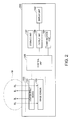
- Fig. 2 is a block diagram showing an electrical configuration of the biological information acquiring device.
- the biological information acquiring device 200 is a portable information terminal device to be worn on the wrist of a human body M.
- the position of a blood vessel in a living body can be specified from image information of the blood vessel within the wrist, or the blood-sugar level can be specified by non-invasively and optically detecting the content of a specific component, such as glucose, in the blood of the blood vessel.
- the biological information acquiring device 200 includes a ring-shaped belt 164 that can be worn on the wrist, a main body unit 160 attached on the outer side of the belt 164, and a sensor unit 150 attached on the inner side of the belt 164 at a position opposed to the main body unit 160.
- the main body unit 160 includes a main body case 161 and a display unit 162 incorporated into the main body case 161.
- a display unit 162 incorporated into the main body case 161.
- operation buttons 163, a circuit system (see Fig. 2 ) such as a control unit 165 described later, a battery as a power supply, and the like are incorporated into the main body case 161.
- the sensor unit 150 includes, as a light-receiving unit, an image sensor 100 as the photoelectric conversion device according to the embodiment (see Fig. 2 ).
- the sensor unit 150 is electrically connected with the main body unit 160 by means of a wiring (not shown in Fig. 1 ) incorporated into the belt 164.
- the image sensor 100 includes a plurality of photosensors 50 as photoelectric conversion elements.
- Each of the photosensors 50 includes a photodiode 20 as a light-receiving element (see Fig. 4 ).
- the biological information acquiring device 200 is worn on the wrist in use such that the sensor unit 150 is in contact with the wrist on the palm side of the hand opposite to the back of the hand. By wearing the biological information acquiring device 200 in this manner, it is possible to avoid a fluctuation in the detection sensitivity of the sensor unit 150 due to skin colors.
- the biological information acquiring device 200 has a configuration in which the main body unit 160 and the sensor unit 150 are separately incorporated with the belt 164
- the biological information acquiring device 200 may have a configuration in which the main body unit 160 and the sensor unit 150 are integrated together and incorporated with the belt 164.
- the biological information acquiring device 200 includes the control unit 165, and the sensor unit 150, a storage unit 167, an output unit 168, and a communication unit 169 that are electrically connected to the control unit 165. Moreover, the biological information acquiring device 200 includes the display unit 162 electrically connected to the output unit 168.
- the sensor unit 150 includes a light-emitting device 130 and the image sensor 100.
- the light-emitting device 130 and the image sensor 100 are electrically connected to the control unit 165.
- the light-emitting device 130 includes a light source portion that emits near-infrared light IL at a wavelength ranging from 700 nm to 2000 nm.
- the control unit 165 drives the light-emitting device 130 to cause the light-emitting device 130 to emit the near-infrared light IL.
- the near-infrared light IL propagates into the human body M and scatters therein. A portion of the near-infrared light IL that has scattered in the human body M can be received as reflected light RL by the image sensor 100.
- the control unit 165 can cause the storage unit 167 to store information of the reflected light RL received by the image sensor 100.
- the control unit 165 causes the output unit 168 to process the information of the reflected light RL.
- the output unit 168 converts the information of the reflected light RL into image information of blood vessels and outputs the image information, or converts the information of the reflected light RL into information of the content of a specific component in the blood and outputs the information.
- the control unit 165 can cause the display unit 162 to display the converted image information of blood vessels or the information of the specific component in the blood. Then, the control unit 165 can transmit the information from the communication unit 169 to another information processor.
- control unit 165 can receive information such as a program from another information processor via the communication unit 169, and cause the storage unit 167 to store the information.
- the communication unit 169 may be a wired communication unit that is connected with another information processor by means of a wire, or a wireless communication unit such as Bluetooth (registered trademark).
- the control unit 165 may cause the display unit 162 to display, not only the information about the acquired blood vessel or blood, but also the information of the program previously stored in the storage unit 167 or information such as a current time.
- the storage unit 167 may be a detachable memory.
- Fig. 3 is a schematic perspective view showing a configuration of the sensor unit.
- Fig. 4 is a schematic cross-sectional view showing a structure of the sensor unit.
- the sensor unit 150 includes the image sensor 100, a light-shielding portion 110, a variable spectral portion 120, the light-emitting device 130, and a protective portion 140. Each of these portions has a plate shape.
- the sensor unit 150 is configured such that the light-shielding portion 110, the variable spectral portion 120, the light-emitting device 130, and the protective portion 140 are stacked in this order on the image sensor 100.
- the sensor unit 150 includes a case (not shown) that accommodates a stacked body including the portions stacked on top of one another and can be attached to the belt 164.
- a direction along one side portion of the stacked body is defined as an X-direction
- a direction along another side portion orthogonal to the one side portion is defined as a Y-direction
- a direction along a thickness direction of the stacked body is defined as a Z-direction.
- viewing the sensor unit 150 from a normal direction (Z-direction) of the protective portion 140 is referred to as "plan view".
- the light-emitting device 130 includes a light-transmissive substrate main body 131, light source portions 133 provided on one surface 131a of the substrate main body 131, and light-transmissive portions 132.
- the light source portion 133 for example, an LED element, an organic electroluminescence element, or the like can be used.
- the protective portion 140 is provided so as to overlap the light source portions 133 and the light-transmissive portions 132.
- the protective portion 140 is, for example, a cover glass or a transparent plate such as plastic.
- the human body M is disposed so as to be in contact with one surface 140a of the protective portion 140.
- the light source portion 133 is configured so as to allow the near-infrared light IL to be emitted to the protective portion 140 side.
- the reflected light RL which is a portion of the near-infrared light IL that has scattered in the human body M, transmits through the light-transmissive portion 132 and is guided to the variable spectral portion 120 in a lower layer.
- the variable spectral portion 120 includes fixed substrates 121 and movable substrates 122.
- a spectral distribution (spectral characteristic) of the reflected light RL transmitting through the variable spectral portion 120 can be changed by electrically controlling a gap between the fixed substrate 121 and the movable substrate 122.
- the reflected light RL that has transmitted through the variable spectral portion 120 is guided to the light-shielding portion 110 in a lower layer.
- the light-shielding portion 110 includes a light-transmissive substrate main body 111 and a light-shielding film 113 provided on a surface 111b of the substrate main body 111 on the side opposite to a surface 111a thereof on the variable spectral portion 120 side. Openings (pinholes) 112 are formed in the light-shielding film 113 at positions corresponding to the arrangement of the light-transmissive portions 132 of the light-emitting device 130.
- the light-shielding portion 110 is disposed between the variable spectral portion 120 and the image sensor 100 such that only the reflected light RL that has transmitted through the openings 112 is guided to the photodiodes 20 while the other reflected light RL is blocked by the light-shielding film 113.
- the image sensor 100 has high photosensitivity to the near-infrared light. A detailed configuration of the image sensor 100 will be described later.
- the image sensor 100 is disposed such that the side thereof on which the photodiodes 20 are provided faces the light-shielding portion 110.
- Each of the plurality of photodiodes 20 is disposed at a position corresponding to the arrangement of the opening 112 in the light-shielding portion 110.
- the reflected light RL that has transmitted through the opening 112 is incident on the photodiode 20.
- a filter that cuts off light in, for example, the visible light wavelength range (400 nm to 700 nm) may be disposed corresponding to the light-transmissive portions 132 of the light-emitting device 130 or the openings 112 of the light-shielding portion 110.
- the configuration of the sensor unit 150 is not limited to that described above.
- the light-emitting device 130 may be configured to include the protective portion 140, and may have a structure in which the light source portions 133 are sealed by the protective portion 140.
- the light-emitting device 130 and the variable spectral portion 120 may be bonded together such that, for example, a surface 131b of the substrate main body 131 of the light-emitting device 130 is in contact with the variable spectral portion 120.
- variable spectral portion 120 and the surface 111a of the light-shielding portion 110 may be bonded together so as to be in contact with each other. By doing this, a positional relationship therebetween in a thickness direction (Z-direction) thereof can be ensured.
- the image sensor 100 as a photoelectric conversion device according to a first embodiment will be described with reference to Figs. 5 and 6 .
- the image sensor 100 includes the plurality of photosensors 50 as photoelectric conversion elements.
- Fig. 5 is an equivalent circuit diagram showing an electrical configuration of a photosensor according to the first embodiment.
- Fig. 6 is a schematic cross-sectional view showing a configuration of the photosensor according to the first embodiment.
- the image sensor 100 includes a plurality of scanning lines 3a and a plurality of readout lines 14 intersecting the scanning lines 3a.
- the scanning lines 3a extend along the X-direction, while the readout lines 14 extend along the Y-direction.
- the photosensor 50 is provided corresponding to the intersection between the scanning line 3a and the readout line 14.
- the photosensor 50 includes the photodiode 20 as a light-receiving element, an amplifying transistor 11, a reset transistor 12, and a selection transistor 13.
- the amplifying transistor 11, the reset transistor 12, and the selection transistor 13 are each composed of a thin film transistor (TFT) .
- An anode of the photodiode 20 is connected to a negative power supply line 17, and a negative power supply potential Vss is supplied to the negative power supply line 17.
- a cathode of the photodiode 20 is connected to a gate of the amplifying transistor 11 and a source of the reset transistor 12.
- a drain of the amplifying transistor 11 and a drain of the reset transistor 12 are connected to a positive power supply line 16, and a positive power supply potential Vdd is supplied to the positive power supply line 16.
- a source of the amplifying transistor 11 and a drain of the selection transistor 13 are connected.
- a source of the selection transistor 13 is connected to the readout line 14, and a gate of the selection transistor 13 is connected to the scanning line 3a.
- a gate of the reset transistor 12 is connected to a reset signal line 15.
- the measurement of the amount of light is performed by the photosensor 50 as follows: First, the gate of the amplifying transistor 11 is charged to the positive power supply potential Vdd. Next, the photodiode 20 is exposed to light over, for example, a period ⁇ . During this exposure period, the reset transistor 12 is in an OFF state. Therefore, a gate potential Vg of the amplifying transistor 11 changes in response to a junction leakage current I of the photodiode 20.
- C T is a transistor capacity of the amplifying transistor 11.
- the junction leakage current is larger as the amount of light is larger, and therefore, the gate potential Vg of the amplifying transistor 11 changes in response to the amount of light.
- a change in the conductance of the amplifying transistor 11 occurring as a result of the change in the gate potential is measured for each of the photosensors 50 during a readout period, whereby the amount of light emitted during the exposure period can be measured.
- the photosensor 50 according to the first embodiment includes a substrate 10 and the photodiode 20 provided on the substrate 10.
- the photodiode 20 according to the first embodiment is composed of a lower electrode 21 as a first electrode, an intermediate layer 22 as a selenized film, a p-type semiconductor layer 23, an n-type semiconductor layer 24, and an upper electrode 25 as a second electrode, which are stacked in this order from the substrate 10 side.
- Fig. 6 is a cross-sectional view of the photosensor 50 along the Y-direction, in which a direction from the near side of Fig. 6 to the far side is the X-direction and an upward direction is the Z-direction.
- viewing the photosensor 50 from the normal direction (Z-direction) of the photodiode 20 is referred to as "plan view”.
- the substrate 10 includes a substrate main body 1, an insulating film 1a, the amplifying transistor 11, a gate insulating film 3, an inter-layer insulating film 4, a relay wiring 5, the positive power supply line 16, the negative power supply line 17, an insulating film 6, and a planarizing layer 7.
- the substrate main body 1 is made of, for example, a transparent glass, opaque silicon, or the like.
- the insulating film 1a is formed so as to cover the surface of the substrate main body 1.
- the amplifying transistor 11 includes a semiconductor layer 2 and a gate electrode 3g.
- the semiconductor layer 2 is formed of, for example, polycrystalline silicon, and provided in an island-shape on the insulating film 1a.
- the semiconductor layer 2 includes a channel region 2c, a drain region 2d, and a source region 2s.
- the gate insulating film 3 is formed of an insulating material such as SiO 2 (silicon oxide) so as to cover the semiconductor layer 2.
- the gate electrode 3g is formed on the gate insulating film 3 at a position opposed to the channel region 2c of the semiconductor layer 2.
- the inter-layer insulating film 4 is formed so as to cover the gate insulating film 3 and the gate electrode 3g.
- the relay wiring 5, the positive power supply line 16, and the negative power supply line 17 are formed using a metal material such as Al (aluminum) on the inter-layer insulating film 4.
- the relay wiring 5 is electrically connected to the gate electrode 3g via a through-hole that penetrates the inter-layer insulating film 4.
- the positive power supply line 16 is electrically connected to the drain region 2d of the semiconductor layer 2 via a through-hole that penetrates the inter-layer insulating film 4 and the gate insulating film 3.
- the insulating film 6 is formed so as to cover the relay wiring 5, the positive power supply line 16, and the negative power supply line 17.
- the insulating film 6 is formed using, for example, SiN (silicon nitride) or the like.
- the planarizing layer 7 is formed so as to cover the insulating film 6.
- the planarizing layer 7 is formed using, for example, SiO 2 (silicon oxide) or the like.
- a through-hole 7a is formed in the insulating film 6 and the planarizing layer 7 at a position overlapping the negative power supply line 17 in the plan view.
- a through-hole 7b is formed in the insulating film 6 and the planarizing layer 7 at a position overlapping the relay wiring 5 in the plan view.
- the lower electrode 21 as the first electrode and a relay electrode 26 as a third electrode are formed in the same layer on the substrate 10 (on the planarizing layer 7).
- the lower electrode 21 and the relay electrode 26 are composed of a conductive film containing a high-melting-point metal as a first metal.
- the lower electrode 21 and the relay electrode 26 can be formed by depositing and patterning one conductive film in the same layer, and therefore, the photosensor 50 can be of a simple configuration.
- Examples of the high-melting-point metal constituting the lower electrode 21 and the relay electrode 26 include, for example, molybdenum (Mo), tungsten (W), tantalum (Ta), and niobium (Nb).
- Mo has favorable electrical characteristics and is easy to manufacture, and thus is suitably used as the material of the lower electrode 21 and the relay electrode 26.
- the conductive film that constitutes the lower electrode 21 is deposited so as to fill the through-hole 7a provided in the insulating film 6 and the planarizing layer 7.
- the conductive film that fills the through-hole 7a forms a contact hole CNT1.
- the lower electrode 21 is electrically connected to the negative power supply line 17 via the contact hole CNT1.
- the intermediate layer 22 made of a selenide of the high-melting-point metal is formed on the lower electrode 21 so as to be in contact with the lower electrode 21.
- the intermediate layer 22 is a selenized film obtained by selenizing a surface layer portion of the conductive film (a conductive film 21a shown in Fig. 7A ) deposited as the lower electrode 21.
- Mo molybdenum selenide
- MoSe 2 molybdenum selenide
- the intermediate layer 22 is disposed inside the outer shape of the lower electrode 21 in the plan view.
- the lower electrode 21 includes a peripheral edge portion located around the intermediate layer 22 in the plan view and not overlapping the intermediate layer 22.
- the layer thickness of the peripheral edge portion of the lower electrode 21 is, for example, about 250 nm.
- the layer thickness of the lower electrode 21 at a portion overlapping the intermediate layer 22 in the plan view is thinner than the layer thickness of the peripheral edge portion, and is, for example, about 200 nm.
- the layer thickness of the intermediate layer 22 is, for example, about 100 nm.
- a portion for forming the contact hole CNT1 that is, a portion to be electrically connected with the negative power supply line 17 via the through-hole 7a is also selenized on the surface layer side. If so, since the layer thickness of the conductive film not being selenized but remaining is reduced by that amount, a wiring resistance at the portion of the contact hole CNT1 is increased. In the embodiment, since the conductive film constituting the lower electrode 21 is not selenized in a region other than that overlapping the p-type semiconductor layer 23, in the plan view, to be formed in a higher layer, the wiring resistance at the portion of the contact hole CNT1 is minimized.
- the conductive film constituting the relay electrode 26 is deposited so as to fill the through-hole 7b formed in the insulating film 6 and the planarizing layer 7. A portion of the conductive film constituting the relay electrode 26, which fills the through-hole 7b, forms a contact hole CNT2.
- the relay electrode 26 is electrically connected to the relay wiring 5 via the contact hole CNT2, and is electrically connected to the gate electrode 3g via the relay wiring 5.
- the layer thickness of the relay electrode 26 is the same as the layer thickness of the peripheral edge portion of the lower electrode 21, and is, for example, about 250 nm. Hence, the layer thickness of the lower electrode 21 at a portion overlapping the intermediate layer 22 in the plan view is thinner than the layer thickness of the relay electrode 26. Moreover, a selenized film like the intermediate layer 22 is not formed on the relay electrode 26. That is, since the conductive film constituting the relay electrode 26 is not selenized, the wiring resistance of the relay electrode 26 including the portion that forms the contact hole CNT2 to be electrically connected with the relay wiring 5 can be minimized.
- An insulating layer 8 is formed so as to cover the substrate 10 (the planarizing layer 7), the lower electrode 21, and the relay electrode 26.
- the insulating layer 8 includes an opening 8a overlapping the lower electrode 21 in the plan view, and an opening 8b overlapping the relay electrode 26 in the plan view.
- the opening 8a is disposed, inside the outer shape of the lower electrode 21 in the plan view, so as to overlap the intermediate layer 22.
- the outer shape of the lower electrode 21 is larger than the opening 8a, and the intermediate layer 22 is disposed in a region overlapping the opening 8a in the plan view.
- the insulating layer 8 is composed of, for example, SiO x (silicon oxide) or SiN x (silicon nitride). In the embodiment, the insulating layer 8 is formed of SiN, and the layer thickness of the insulating layer 8 is, for example, about 200 nm.
- the p-type semiconductor layer 23 is formed on the intermediate layer 22.
- the p-type semiconductor layer 23 is disposed, for example, inside the outer shape of the intermediate layer 22 in the plan view. That is, the p-type semiconductor layer 23 is disposed inside the opening 8a of the insulating layer 8.
- the p-type semiconductor layer 23 may be formed larger than the opening 8a such that a peripheral edge portion of the p-type semiconductor layer 23 rides up over the insulating layer 8.
- the p-type semiconductor layer 23 is composed of a CIS-based (CuInSe 2 ) semiconductor film with chalcopyrite structure containing copper (Cu) as a Group 11 element, indium (In) as a Group 13 element, and selenium (Se) as a Group 16 element.
- the p-type semiconductor layer 23 may be composed of a CIGS-based (Cu(In,Ga)Se 2 ) film with chalcopyrite structure containing copper (Cu), indium (In), gallium (Ga) as a Group 13 element, and selenium (Se).
- the CIS-based and CIGS-based films with chalcopyrite structure have excellent photoelectric conversion rates and high photosensitivity over a wide range of wavelengths from the visible light to the near-infrared light.
- the intermediate layer 22 is disposed between the lower electrode 21 and the p-type semiconductor layer 23. That is, the intermediate layer 22 is in contact with the lower electrode 21, and the p-type semiconductor layer 23 is in contact with the intermediate layer 22. Due to this, compared to the case where the lower electrode 21 and the p-type semiconductor layer 23 are in contact with each other, an ohmic contact is obtained at each of boundaries between the lower electrode 21 and the intermediate layer 22 and between the intermediate layer 22 and the p-type semiconductor layer 23. Therefore, the contact resistance between the lower electrode 21 and the p-type semiconductor layer 23 can be minimized.
- a protective layer 9 is formed so as to cover the insulating layer 8, the intermediate layer 22, and the p-type semiconductor layer 23.
- the protective layer 9 is composed of, for example, SiO x or SiN x .
- the protective layer 9 is formed of SiN, and the layer thickness of the protective layer 9 is, for example, about 500 nm.
- the protective layer 9 includes an opening 9a overlapping the p-type semiconductor layer 23 in the plan view, and a through-hole 9b overlapping the relay electrode 26 in the plan view.
- the opening 9a is disposed inside the outer shape of the p-type semiconductor layer 23 in the plan view.
- the through-hole 9b is disposed, for example, inside the opening 8b of the insulating layer 8, and formed so as to penetrate the protective layer 9 until the through-hole 9b reaches the relay electrode 26.
- the through-hole 9b may be formed to have the same plane area as the opening 8b.
- the n-type semiconductor layer 24 is stacked and formed on the p-type semiconductor layer 23.
- the n-type semiconductor layer 24 is formed, for example, larger than the opening 9a such that a peripheral edge portion of the n-type semiconductor layer 24 rides up over the protective layer 9.
- the n-type semiconductor layer 24 may be composed of, for example, an i-ZnO (intrinsic zinc oxide) film as an undoped intrinsic semiconductor film and an n-type impurity-doped ZnO (n + ) film.
- the "intrinsic semiconductor film” means a semiconductor film to which donor atoms or acceptor atoms are not added on purpose.
- an intrinsic semiconductor film is stacked on the p-type semiconductor layer 23, and further, an n-type impurity-doped semiconductor film is stacked on the intrinsic semiconductor film.
- the upper electrode 25 is formed on the protective layer 9 so as to cover the n-type semiconductor layer 24.
- the upper electrode 25 is formed of a light-transmissive conductive film such as ITO (Indium Tin Oxide) or IZO (Indium Zinc Oxide) .
- the conductive film constituting the upper electrode 25 extends to a region overlapping the relay electrode 26 in the plan view, and is deposited so as to fill the through-hole 9b of the protective layer 9.
- the upper electrode 25 is electrically connected to the relay electrode 26 via the contact hole CNT3, is electrically connected to the relay wiring 5 via the contact hole CNT2, and is further electrically connected to the gate electrode 3g via the relay wiring 5.
- the conductive film constituting the upper electrode 25 is in contact with the relay electrode 26. Since a selenized film like the intermediate layer 22 on the lower electrode 21 is not formed on the relay electrode 26, the contact resistance between the relay electrode 26 and the upper electrode 25 can be minimized.
- the lower electrode 21, the intermediate layer 22, the p-type semiconductor layer 23, the n-type semiconductor layer 24, and the upper electrode 25 constitute the photodiode 20.
- a region not covered with the protective layer 9 in the region of the p-type semiconductor layer 23 and the n-type semiconductor layer 24, that is, a region disposed inside the opening 9a in the plan view is a light-receiving region 50a.
- the photosensor 50 when light is incident on the light-receiving region 50a, a photocurrent in response to the amount of the light flows in the photodiode 20.
- the photodiode 20 includes the p-type semiconductor layer 23 with chalcopyrite structure, and therefore has an excellent photoelectric conversion rate and high photosensitivity over the wide range of wavelengths from the visible light to the near-infrared light.
- the intermediate layer 22 composed of a selenized film is disposed between the lower electrode 21 and the p-type semiconductor layer 23 in the photodiode 20
- an ohmic contact is obtained at each of the boundaries between the lower electrode 21 and the intermediate layer 22 and between the intermediate layer 22 and the p-type semiconductor layer 23. Therefore, the contact resistance between the lower electrode 21 and the p-type semiconductor layer 23 can be minimized.
- the wiring resistance can be minimized. Due to these, it is possible to provide the image sensor 100 that stably operates with high sensitivity over the wide range of wavelengths from the visible light to the near-infrared light.
- Figs. 7A to 9C are diagrams for explaining the method for manufacturing the photosensor according to the first embodiment.
- Each of Figs. 7A to 9C corresponds to the partially enlarged view in Fig. 6 .
- the substrate 10 is prepared.
- the substrate 10 is obtained by forming, on the substrate main body 1, transistors such as the amplifying transistor 11, the inter-layer insulating film 4, the insulating film 6, the planarizing layer 7, and the like (see Fig. 6 ) using a publicly known semiconductor manufacturing technique.
- the through-hole 7a penetrating the insulating film 6 and the planarizing layer 7 to reach the negative power supply line 17 is formed in a region overlapping the negative power supply line 17 in the plan view in the substrate 10.
- the through-hole 7b penetrating the insulating film 6 and the planarizing layer 7 to reach the relay wiring 5 is formed in a region overlapping the relay wiring 5 in the plan view in the substrate 10.
- the conductive film 21a containing a high-melting-point metal is deposited to a film thickness of 100 nm or more and 500 nm or less on the substrate 10 using, for example, physical vapor deposition (PVD). Due to this, the conductive film 21a is formed so as to cover the substrate 10 and fill the through-hole 7a and the through-hole 7b.
- the film thickness of the conductive film 21a is 100 nm or more, an increase in the wiring resistance of the conductive film 21a serving as the lower electrode 21 and the relay electrode 26 can be suppressed.
- the film thickness of the conductive film 21a is 500 nm or less, a situation in which a difference in level caused by the lower electrode 21 and the relay electrode 26 is increased can be suppressed, and at the same time, the film peeling-off caused by a large internal stress due to a thick film can be suppressed.
- the conductive film 21a is deposited to a film thickness of 250 nm by a sputtering method using Mo (molybdenum) as the high-melting-point metal.
- the conductive film 21a is patterned to form a lower electrode film 21b and the relay electrode 26.
- the conductive film of the lower electrode film 21b which fills the through-hole 7a, forms the contact hole CNT1.
- the lower electrode film 21b is electrically connected to the negative power supply line 17 via the contact hole CNT1.
- the conductive film of the relay electrode 26, which fills the through-hole 7b forms the contact hole CNT2.
- the relay electrode 26 is electrically connected to the relay wiring 5 via the contact hole CNT2.
- the insulating layer 8 made of SiO x or SiN x is formed so as to cover the substrate 10 (the planarizing layer 7), the lower electrode film 21b, and the relay electrode 26.
- the insulating layer 8 is formed to a film thickness of 50 nm or more and 700 nm or less using, for example, chemical vapor deposition (CVD).
- the insulating layer 8 plays a role of suppressing the selenization of the lower electrode film 21b at a portion other than a desired region (region for forming the intermediate layer 22 shown in Fig. 8A ) in a step of applying a heat treatment described later.
- the film thickness of the insulating layer 8 is 50 nm or more, covering properties for covering the lower electrode film 21b and the relay electrode 26 can be ensured. On the other hand, when the film thickness of the insulating layer 8 is 700 nm or less, the film peeling-off caused by a large internal stress due to a thick film can be suppressed.
- the film thickness of the insulating layer 8 is preferably from 100 nm to 300 nm. In the embodiment, the insulating layer 8 made of SiN is formed to a film thickness of 200 nm.
- the opening 8a is formed in a region overlapping the lower electrode film 21b in the plan view in the insulating layer 8.
- the opening 8a is formed to have an area smaller than the outer shape of the lower electrode film 21b, in the region not overlapping the contact hole CNT1 in the plan view. Due to this, a region of the lower electrode film 21b, which is a portion except for the contact hole CNT1 and located inside the outer shape of the lower electrode film 21b, is exposed through the opening 8a.
- the relay electrode 26 is covered with the insulating layer 8.
- a metal film containing a Group 11 element and a Group 13 element is formed on the lower electrode film 21b.
- a metal film 23a made of copper (Cu) as a Group 11 element and a metal film 23b made of indium (In) as a Group 13 element are stacked and deposited using a sputtering method so as to cover the lower electrode film 21b exposed in the opening 8a and the insulating layer 8.
- a heat treatment is applied to the metal film 23a and the metal film 23b in an atmosphere of gas containing a Group 16 element.
- a Group 16 element for example, selenium (Se), sulfur (S), tellurium (Te), or the like can be used.
- the temperature of the heat treatment is set to, for example, 400°C or more and 550°C or less.
- hydrogen selenide H 2 Se
- the heat treatment is applied at a temperature of 450°C in the H 2 Se atmosphere.
- Hydrogen sulfide H 2 S
- a heat treatment may be further applied in the H 2 S atmosphere after a heat treatment is applied in the H 2 Se atmosphere.
- This heat treatment is a treatment to allow the metal film 23a and the metal film 23b to react with a Group 16 element to thereby be converted into the p-type semiconductor layer 23 (see Fig. 8A ) with chalcopyrite structure.
- the temperature of the heat treatment is 400°C or more, the metal film 23a and the metal film 23b favorably react with a Group 16 element.
- the temperature of the heat treatment is 550°C or less, the occurrence of undesirable effects such as the deformation of the substrate 10 (the substrate main body 1) or the deposition of metal due to exposure to a high temperature is suppressed.
- the p-type semiconductor layer 23 composed of a semiconductor film with chalcopyrite structure is formed as shown in Fig. 8A .
- the metal film 23a (Cu) and the metal film 23b (In) are selenized to form the p-type semiconductor layer 23 composed of a CIS (CuInSe 2 ) -based film.
- a metal film further containing gallium (Ga) as a Group 13 element, in addition to Cu and In may be formed.
- Ga gallium
- a metal film 23a made of an alloy of Cu and Ga is deposited, and the metal film 23b made of In is stacked on the metal film 23a.
- the metal film 23a (CuGa) and the metal film 23b (In) are selenized to form the p-type semiconductor layer 23 composed of a CIGS (Cu (In, Ga) Se 2 ) -based film.
- a surface layer portion of the lower electrode film 21b (Mo) in the region overlapping the opening 8a in the plan view is selenized by applying the heat treatment in the H 2 Se atmosphere, so that a molybdenum selenide (MoSe 2 ) film as a selenide of molybdenum is formed.
- This selenized film serves as the intermediate layer 22.
- the Mo film of the lower electrode film 21b at a non-selenized portion (the lower side of the intermediate layer 22 in the region overlapping the opening 8a in the plan view, and a portion not overlapping the opening 8a in the plan view) serves as the lower electrode 21.
- the intermediate layer 22 is disposed between the lower electrode 21 and the p-type semiconductor layer 23.
- the p-type semiconductor layer 23 with chalcopyrite structure is formed, and at the same time, the selenized film obtained by selenizing molybdenum is formed as the intermediate layer 22 between the lower electrode 21 and the p-type semiconductor layer 23 in the opening 8a. Therefore, since an ohmic contact is obtained at a boundary between the lower electrode 21 and the intermediate layer 22 and at a boundary between the intermediate layer 22 and the p-type semiconductor layer 23, the contact resistance between the lower electrode 21 and the p-type semiconductor layer 23 can be minimized. Moreover, the adhesion of these layers at their interfaces can be improved.
- the film thickness of the intermediate layer 22 is preferably 100 nm or less. As the film thickness of the intermediate layer 22 is thicker, the film thickness of the Mo film remaining as the lower electrode 21 becomes thinner and thus the wiring resistance is increased. Further, when the lower electrode film 21b is selenized throughout its entire film thickness, the lower electrode 21 (Mo film) does not remain, and thus the p-type semiconductor layer 23 peels off from the substrate 10.
- the film thickness of the MoSe 2 film is multiple times the film thickness of the original Mo film.
- the original film thickness of the lower electrode film 21b is 250 nm
- the film thicknesses of the intermediate layer 22 (MoSe 2 film) and the remaining lower electrode 21 (Mo film) are about 100 nm and about 200 nm, respectively.
- the insulating layer 8 is not formed in the heat treatment described above, surface layer portions of the lower electrode film 21b and the relay electrode 26 are selenized in the entire planar region.
- the wiring resistance is increased in the entire region of the lower electrode 21 including the contact hole CNT1 and the relay electrode 26 including the contact hole CNT2.
- the selenized film lies between the relay electrode 26 and the upper electrode 25 to be formed in contact with the relay electrode 26 in a later step, and thus the contact resistance between the upper electrode 25 and the relay electrode 26 is increased.
- a region of the lower electrode film 21b other than the region for forming the intermediate layer 22 and the entire region of the relay electrode 26 are covered with the insulating layer 8 in the embodiment. Therefore, the selenization in these regions can be suppressed in the heat treatment. Due to this, the wiring resistances of the lower electrode 21 including the contact hole CNT1 and the relay electrode 26 including the contact hole CNT2 can be minimized, and at the same time, the contact resistance between the upper electrode 25 and the relay electrode 26 can be minimized.
- the p-type semiconductor layer 23 may be patterned wider than the opening 8a such that a peripheral edge portion of the p-type semiconductor layer 23 rides up over the insulating layer 8.
- the opening 8b is formed in a region overlapping the relay electrode 26 in the plan view but not overlapping the contact hole CNT2 in the plan view in the insulating layer 8. Due to this, the relay electrode 26 is exposed in the opening 8b.
- the protective layer 9 made of SiO x or SiN x is formed so as to cover the relay electrode 26, the p-type semiconductor layer 23, and the insulating layer 8.
- the protective layer 9 made of SiN is formed to a film thickness of 500 nm using CVD.
- the opening 9a is formed in a region overlapping the p-type semiconductor layer 23 in the plan view in the protective layer 9. Due to this, the p-type semiconductor layer 23 is exposed in the opening 9a.
- an intrinsic semiconductor film and an n-type impurity-doped semiconductor film are stacked on the p-type semiconductor layer 23 to form the n-type semiconductor layer 24.
- an undoped i-ZnO film and an n-type impurity-doped ZnO (n + ) film are stacked and deposited by a sputtering method and then patterned to form the n-type semiconductor layer 24.
- the through-hole 9b reaching the relay electrode 26 is formed for forming the contact hole CNT3 in a region overlapping the opening 8b in the plan view in the protective layer 9. Due to this, the relay electrode 26 is exposed in the through-hole 9b.
- the opening 8b may not be formed in the insulating layer 8 in the step shown in Fig. 8B , and the through-hole 9b may be formed so as to penetrate the protective layer 9 and the insulating layer 8 in the step shown in Fig. 9B .
- the upper electrode 25 is formed of a light-transmissive conductive film so as to cover the n-type semiconductor layer 24 and fill the through-hole 9b.
- an ITO film is deposited by a sputtering method on the n-type semiconductor layer 24 and the protective layer 9 and then patterned to form the upper electrode 25. Due to this, the photodiode 20 including the p-type semiconductor layer 23 and the n-type semiconductor layer 24 stacked and disposed between the lower electrode 21 and the upper electrode 25, and the intermediate layer 22 disposed between the lower electrode 21 and the p-type semiconductor layer 23 is configured.
- the contact hole CNT3 is formed by filling the through-hole 9b with the conductive film constituting the upper electrode 25. Due to this, the upper electrode 25 is electrically connected to the relay electrode 26 via the contact hole CNT3, is electrically connected to the relay wiring 5 via the contact hole CNT2, and is further electrically connected to the gate electrode 3g via the relay wiring 5. As a result, the photosensor 50 including the photodiode 20 is configured.
- the image sensor 100 including the photosensor 50 according to the first embodiment is completed.
- the region for forming the intermediate layer 22 in the lower electrode 21 is selectively selenized, and the selenization of the other region of the lower electrode 21 and the relay electrode 26 can be suppressed by covering them with the insulating layer 8.
- the image sensor 100 having an excellent photoelectric conversion rate, high photosensitivity over the range of wavelengths from the visible light to the near-infrared light, and high reliability.
- a second embodiment differs from the first embodiment in the configuration of the photosensor in the image sensor 100 as a photoelectric conversion device.
- a photosensor 60 according to the second embodiment will be described with reference to Fig. 10.
- Fig. 10 is a schematic cross-sectional view showing a configuration of the photosensor according to the second embodiment.
- the photosensor 60 according to the second embodiment includes the substrate 10 and a photodiode 30 provided on the substrate 10.
- the substrate 10 has the configuration similar to that of the first embodiment.
- the photodiode 30 according to the second embodiment is composed of a lower electrode 31 as a first electrode, the intermediate layer 22 as a selenized film, the p-type semiconductor layer 23, the n-type semiconductor layer 24, and the upper electrode 25 as a second electrode, which are stacked in this order from the substrate 10 side.
- the photosensor 60 includes a relay electrode 34 as a third electrode on the substrate 10 (on the planarizing layer 7).
- the photosensor 60 according to the second embodiment differs from the photosensor 50 according to the first embodiment in that the insulating layer 8 is not provided on the substrate 10 (the planarizing layer 7), and that a metal oxide layer 32 and a metal oxide layer 35 are provided on the lower electrode 31 and the relay electrode 34, respectively.
- the photosensor 60 according to the second embodiment will be described focusing on differences from the photosensor 50 according to the first embodiment.
- the lower electrode 31 and the relay electrode 34 are formed in the same layer on the substrate 10 (on the planarizing layer 7).
- the lower electrode 31 and the relay electrode 34 are composed of a conductive film containing a high-melting-point metal as a first metal, similarly to the first embodiment.
- the planar shape and arrangement of the lower electrode 31 and the relay electrode 34 are similar to the planar shape and arrangement of the lower electrode 21 and the relay electrode 26 in the first embodiment.
- the contact hole CNT1 for electrically connecting to the negative power supply line 17 is formed.
- the contact hole CNT2 for electrically connecting to the relay wiring 5 is formed.
- the metal oxide layer 32 is formed on the lower electrode 31, and the metal oxide layer 35 is formed on the relay electrode 34.
- the metal oxide layer 32 and the metal oxide layer 35 are made of an oxide of the high-melting-point metal constituting the lower electrode 31 and the relay electrode 34. That is, the metal oxide layer 32 and the metal oxide layer 35 are oxidized surface layer portions of the conductive film (the conductive film 21a shown in Fig. 11A ) deposited as the lower electrode 31 and the relay electrode 34.
- Mo molybdenum oxide
- MoO 2 , MoO 3 molybdenum oxide
- the metal oxide layer 32 and the metal oxide layer 35 play a role of suppressing the selenization of a conductive film 31a serving as the lower electrode 31 and the relay electrode 34 other than a portion of the conductive film 31a in a region for forming the intermediate layer 22 in a step of applying a heat treatment for forming the p-type semiconductor layer 23 with chalcopyrite structure (see Fig. 11D ).
- the metal oxide layer 32 formed on the lower electrode 31 includes an opening 33.
- the intermediate layer 22 composed of a selenized film (MoSe 2 , etc.) obtained by selenizing a surface layer portion of the conductive film deposited as the lower electrode 31 is disposed on the lower electrode 31 in a region overlapping the opening 33 in the plan view.
- the layer thickness of the lower electrode 31 at a portion overlapping the intermediate layer 22 in the plan view is thinner than the layer thickness at a peripheral edge portion.
- the layer thickness of the intermediate layer 22 is about the same as that of the first embodiment.
- the layer thickness of the lower electrode 31 at the portion overlapping the intermediate layer 22 in the plan view is thinner than the layer thickness of the relay electrode 34.
- the intermediate layer 22 composed of the selenized film is disposed between the lower electrode 31 and the p-type semiconductor layer 23 of the photodiode 30.
- the contact resistance between the lower electrode 31 and the p-type semiconductor layer 23 can be minimized.
- the adhesion of these layers at their interfaces can be improved. Since the selenized film is not formed in a region of the lower electrode 31 other than a portion thereof in contact with the p-type semiconductor layer 23, the wiring resistance of the lower electrode 31 can be minimized.
- the metal oxide layer 35 formed on the relay electrode 34 includes an opening 36.
- the relay electrode 34 is electrically connected with the upper electrode 25 provided in a higher layer via the contact hole CNT3 formed in a region overlapping the opening 36 in the plan view. Since the metal oxide layer 35 or a selenized film is not formed at a portion of the relay electrode 34 in contact with the upper electrode 25, the contact resistance between the relay electrode 34 and the upper electrode 25 can be minimized. Moreover, since a selenized film is not formed on the relay electrode 34 not only at the portion in contact with the upper electrode 25 but in the entire region, the wiring resistance of the relay electrode 34 can be minimized.
- the layer thickness of the metal oxide layer 32 and the metal oxide layer 35 is preferably from about 10 nm to 100 nm.
- the film thickness of the conductive film deposited as the lower electrode 31 and the relay electrode 34 is set to 250 nm and a surface layer-side portion of the conductive film with a layer thickness of 50 nm is oxidized, the surface layer side of the conductive film becomes thick by oxidation, and thus the metal oxide layer 32 and the metal oxide layer 35 each with a layer thickness of about 100 nm are formed.
- the conductive film with a layer thickness of about 200 nm remains as the lower electrode 31 and the relay electrode 34.
- the photodiode 30 according to the second embodiment also includes the p-type semiconductor layer 23 with chalcopyrite structure similarly to the photodiode 20 according to the first embodiment. Therefore, the photodiode 30 has an excellent photoelectric conversion rate and high photosensitivity over the wide range of wavelengths from the visible light to the near-infrared light. Besides, since an ohmic contact is obtained at each of the boundaries between the lower electrode 31 and the intermediate layer 22 and between the intermediate layer 22 and the p-type semiconductor layer 23, the contact resistance between the lower electrode 31 and the p-type semiconductor layer 23 can be minimized.
- the wiring resistance can be minimized. Due to these, it is possible, similarly to the first embodiment, to provide the image sensor 100 that stably operates with high sensitivity over the wide range of wavelengths from the visible light to the near-infrared light.
- Figs. 11A to 13C are diagrams for explaining the method for manufacturing the photosensor according to the second embodiment. Each of Figs. 11A to 13C corresponds to the partially enlarged view in Fig. 10 .
- the conductive film 21a containing a high-melting-point metal such as Mo (molybdenum) is formed so as to cover the substrate 10 (the planarizing layer 7) and fill the through-hole 7a and the through-hole 7b of the planarizing layer 7, similarly to the first embodiment. Also in the second embodiment, the conductive film 21a is deposited to a film thickness of 250 nm by sputtering using Mo (molybdenum) as a high-melting-point metal.
- a metal oxide film 32a is formed by oxidizing the surface layer side of the conductive film 21a.
- a method for forming the metal oxide film 32a for example, sputtering in an oxygen atmosphere, a heat treatment in an oxygen atmosphere (at a high temperature of 250°C or more), or the like can be used.
- the surface layer side of the conductive film 21a (see Fig. 11A ) is oxidized and converted into the metal oxide film 32a, and an unoxidized portion of the conductive film 21a remains as a conductive film 31a.
- the conductive film 31a and the metal oxide film 32a covering the conductive film 31a are formed on the substrate 10.
- the film thickness of the metal oxide film 32a is preferably from about 10 nm to 100 nm as described above.
- the film thickness of the metal oxide film 32a is 10 nm, the selenization of the conductive film 31a other than that in the region for forming the intermediate layer 22 can be favorably suppressed in a heat treatment described later.
- the film thickness of the metal oxide film 32a is 100 nm or less, processing for removing the metal oxide film 32a at the opening 33 can be facilitated in forming the opening 33 in the metal oxide film 32a in the next step.
- the original film thickness of the conductive film 21a is 250 nm, while the film thicknesses of the metal oxide film 32a (MoO x ) and the remaining conductive film 31a (Mo) are about 100 nm and about 200 nm, respectively.
- a portion of the metal oxide film 32a which overlaps the region for forming the intermediate layer 22 in the plan view, is removed by an etching treatment or the like to form the opening 33.
- the amount of etching is appropriately adjusted so as not to excessively reduce the film thickness of the conductive film 31a while definitely removing the metal oxide film 32a in the opening 33. Due to this, the conductive film 31a is exposed in the opening 33 of the metal oxide film 32a.
- the metal film 23a made of copper (Cu) and the metal film 23b made of indium (In) are stacked and deposited using a sputtering method or the like as a metal film containing a Group 11 element and a Group 13 element so as to cover the conductive film 31a exposed in the opening 33 and the metal oxide film 32a.
- a heat treatment is applied to the metal film 23a and the metal film 23b in an atmosphere of gas containing a Group 16 element.
- hydrogen selenide H 2 Se
- the heat treatment is applied in the H 2 Se atmosphere at a temperature of 450°C.
- the p-type semiconductor layer 23 composed of a semiconductor film with chalcopyrite structure is formed as shown in Fig. 12A .
- the p-type semiconductor layer 23 composed of a CIS (CuInSe 2 )-based film is formed.
- a surface layer portion of the conductive film 31a (Mo) in a region overlapping the opening 33 in the plan view is selenized, so that the intermediate layer 22 composed of a molybdenum selenide (MoSe 2 ) film is formed.
- the intermediate layer 22 is disposed between the conductive film 31a serving as the lower electrode 31 and the p-type semiconductor layer 23.
- the original film thickness of the conductive film 31a is 200 nm, while the film thicknesses of the intermediate layer 22 (MoSe 2 ) and the remaining conductive film 31a (Mo) are about 100 nm and about 150 nm, respectively.
- the layer thickness of the conductive film 31a at a portion overlapping the intermediate layer 22 in the plan view is thinner the layer thickness of the conductive film 31a in the other region including a portion serving as the relay electrode 34 in a later step.
- the metal film 23a (and the metal film 23b) deposited in the step shown in Fig. 11D is in contact with the conductive film 31a in the opening 33 of the metal oxide film 32a, and is in contact with the metal oxide film 32a in a region other than that in the opening 33.
- the p-type semiconductor layer 23 formed through the heat treatment and shown in Fig. 12A is in contact with the intermediate layer 22 in the opening 33 of the metal oxide film 32a, and is in contact with the metal oxide film 32a in a region other than that in the opening 33.
- the adhesion between the p-type semiconductor layer 23 (or the metal film 23a before the heat treatment) and the metal oxide film 32a is more favorable than the adhesion between the p-type semiconductor layer 23 (or the metal film 23a before the heat treatment) and the insulating layer 8 in the first embodiment.
- the adhesion of the p-type semiconductor layer 23 (or the metal film 23a before the heat treatment) to the substrate 10 side is improved in the second embodiment. Therefore, the lifting or film peeling-off of the p-type semiconductor layer 23 (or the metal film 23a and the metal film 23b stacked on each other) is less likely to occur between the step shown in Fig. 11D and the step shown in Fig. 12B than in the first embodiment. Due to this, stable production and improved manufacturing yield can be achieved in the second embodiment compared to the first embodiment.
- the conductive film 31a is patterned to form the lower electrode 31 and the relay electrode 34.
- the metal oxide film 32a is also patterned by patterning the conductive film 31a, so that the metal oxide layer 32 and the metal oxide layer 35 are disposed on the lower electrode 31 and the relay electrode 34, respectively.
- the protective layer 9 made of SiO x or SiN x is formed so as to cover the lower electrode 31, the metal oxide layer 32, the p-type semiconductor layer 23, the relay electrode 34, and the metal oxide layer 35. Then, the opening 9a is formed in a region overlapping the p-type semiconductor layer 23 in the plan view in the protective layer 9. Due to this, the p-type semiconductor layer 23 is exposed in the opening 9a.
- an intrinsic semiconductor film such as an undoped i-ZnO film and a semiconductor film such as an n-type impurity-doped ZnO (n + ) film are stacked on the p-type semiconductor layer 23 by a sputtering method or the like to form the n-type semiconductor layer 24.
- the through-hole 9b reaching the relay electrode 34 is formed for forming the contact hole CNT3 in a region overlapping the opening 36 of the metal oxide layer 35 in the plan view in the protective layer 9. Due to this, the relay electrode 34 is exposed in the through-hole 9b.
- the upper electrode 25 is formed of a light-transmissive conductive film such as an ITO film by a sputtering method or the like so as to cover the n-type semiconductor layer 24 and fill the through-hole 9b. Due to this, as shown in Fig. 10 , the photodiode 30 including the p-type semiconductor layer 23 and the n-type semiconductor layer 24 stacked and disposed between the lower electrode 31 and the upper electrode 25, and the intermediate layer 22 disposed between the lower electrode 31 and the p-type semiconductor layer 23 is configured.
- a light-transmissive conductive film such as an ITO film by a sputtering method or the like
- the contact hole CNT3 is formed by filling the through-hole 9b with the conductive film constituting the upper electrode 25. Due to this, the upper electrode 25 is electrically connected to the relay electrode 34 via the contact hole CNT3, is electrically connected to the relay wiring 5 via the contact hole CNT2, and is further electrically connected to the gate electrode 3g via the relay wiring 5. As a result, the photosensor 60 including the photodiode 30 is configured.
- the image sensor 100 including the photosensor 60 according to the second embodiment is completed.
- the region of the lower electrode 31 for forming the intermediate layer 22 is selectively selenized, and the selenization of the other region of the lower electrode 31 and the relay electrode 34 can be suppressed by covering them with the metal oxide layer 32 and the metal oxide layer 35, similarly to the first embodiment.
- the occurrence of lifting or film peeling-off of the p-type semiconductor layer 23 can be suppressed to achieve stable production and improved manufacturing yield.
- the second embodiment has a configuration in which the metal oxide film 32a formed on the conductive film 31a in the step shown in Fig. 11B remains, also in the completed state of the photosensor 60 shown in Fig. 10 , as the metal oxide layer 32 on the lower electrode 31 and the metal oxide layer 35 on the relay electrode 34.
- the invention is not limited to such a form.
- the invention may adopt a configuration in which the metal oxide film 32a (the metal oxide layer 32 and the metal oxide layer 35) does not remain.
- Figs. 14A to 14C are diagrams for explaining a method for manufacturing a photosensor according to Modified Example 1.
- Fig. 14A corresponds to the step of patterning the p-type semiconductor layer 23 to remove the region other than the portion located on the intermediate layer 22 shown in Fig. 12B of the second embodiment.
- the metal oxide film 32a is removed by overetching in the entire region on the conductive film 31a in patterning the p-type semiconductor layer 23. Due to this, since the conductive film 31a is exposed in the entire region including a portion serving as the relay electrode 34, the step of forming the opening 36 in the metal oxide layer 35 to expose the relay electrode 34, shown in Fig. 12D of the second embodiment, becomes unnecessary.
- the conductive film 31a is patterned to form the lower electrode 31 and the relay electrode 34 similarly to the second embodiment, and as shown in Fig. 14B , the protective layer 9 is formed so as to cover the lower electrode 31, the p-type semiconductor layer 23, and the relay electrode 34.
- the through-hole 9b for forming the contact hole CNT3 is formed in the protective layer 9, the relay electrode 34 is exposed in the through-hole 9b.
- the p-type semiconductor layer 23 is composed of a CIS-based or CIGS-based film with chalcopyrite structure containing a Group 11 element, a Group 13 element, and a Group 16 element.
- the invention is not limited to such a form.
- the p-type semiconductor layer 23 may be composed of a CZTS (Cu 2 ZnSnS 4 )-based film containing a Group 11 element, a Group 12 element, a Group 14 element, and a Group 16 element.
- CZTS Cu 2 ZnSnS 4
- a metal film containing copper (Cu) as a Group 11 element, zinc (Zn) as a Group 12 element, and tin (Sn) as a Group 14 element is formed on the lower electrode film 21b and subjected to a heat treatment in an atmosphere containing sulfur (S) as a Group 16 element, whereby the p-type semiconductor layer 23 can be composed of a CZTS-based film.
- the image sensor 100 including the photodiode 20 or the photodiode 30 including the semiconductor film with chalcopyrite structure has been described by way of example as a photoelectric conversion device.
- the photoelectric conversion device may be a solar cell including the photodiode 20 or the photodiode 30 including the semiconductor film with chalcopyrite structure.
- the biological information acquiring device 200 which is a portable information terminal device that can obtain image information of a blood vessel or information of a specific component in blood or the like, has been described by way of example as an electronic apparatus.
- the electronic apparatus may be an information terminal device in a different form such as of a stationary type, or may be a biometric authentication device that acquires image information of a finger vein and compares the image information with previously registered image information of veins to identify an individual.
- the electronic apparatus may be a solid-state imaging device that captures an image of a fingerprint, the eyeball iris, or the like.
Abstract
Description
- The present invention relates to a photoelectric conversion device, a method for manufacturing a photoelectric conversion device, and an electronic apparatus.
- Photoelectric conversion devices including a semiconductor layer composed of a CIS-based film or CGIS-based film with chalcopyrite structure are known (e.g., see
JP-A-2012-169517 JP-A-2012-169517 - Here, when the lower electrode made of a high-melting-point metal and the semiconductor layer with chalcopyrite structure are disposed in contact with each other as in the photoelectric conversion device disclosed in
JP-A-2012-169517 - An advantage of some aspects of the invention is to solve at least a part of the problems described above, and the invention can be implemented as the following forms or application examples.
- A photoelectric conversion device according to this application example includes: a first electrode containing a first metal; a second electrode disposed in a layer higher than the first electrode; a semiconductor layer disposed between the first electrode and the second electrode; and a third electrode containing the first metal, wherein the first electrode and the third electrode are formed in the same layer, and a selenized film of the first metal is formed on the first electrode.
- According to this configuration, since the selenized film of the first metal is formed on the first electrode in the photoelectric conversion device including the semiconductor layer disposed between the first electrode and the second electrode, the selenized film is in contact with the first electrode, and the semiconductor layer is in contact with the selenized film. Therefore, since an ohmic contact is obtained at each of boundaries between the first electrode and the selenized film and between the selenized film and the semiconductor layer, the contact resistance between the first electrode and the semiconductor layer can be minimized compared to the case where the first electrode and the semiconductor layer are in contact with each other. Moreover, the first electrode and the third electrode are formed in the same layer using the same first metal. Therefore, if, for example, the first electrode is an electrode of a light-receiving element and the third electrode is a relay electrode or wiring portion, the photoelectric conversion device can be of simple configuration. Besides, since the selenized film of the first metal is not formed on the third electrode, the wiring resistance of the third electrode can be minimized. Due to these, it is possible to provide the photoelectric conversion device that stably operates with high sensitivity.
- In the photoelectric conversion device of the application example, it is preferable that a layer thickness of the first electrode is thinner than a layer thickness of the third electrode.
- According to this configuration, in the first electrode and the third electrode that are formed in the same layer using the first metal, the layer thickness of the first electrode on which the selenized film is formed is thinner than the layer thickness of the third electrode. It is considered from this that the selenized film on the first electrode is formed by selenizing a surface layer portion of the first electrode, and that a surface layer portion of the third electrode is not selenized. Hence, the wiring resistance of the third electrode can be minimized while minimizing the contact resistance between the first electrode and the semiconductor layer.
- In the photoelectric conversion device of the application example, it is preferable that an insulating layer including an opening is formed on the first electrode and the third electrode, and that the selenized film is disposed in a region overlapping the opening in a plan view.
- According to this configuration, the insulating layer is formed so as to cover the third electrode, and includes the opening overlapping the selenized film on the first electrode in the plan view. Hence, by performing selenization after forming the insulating layer on the first electrode and the third electrode, a region overlapping the opening in the plan view in the first electrode can be selenized without selenizing the third electrode.
- In the photoelectric conversion device of the application example, it is preferable that a metal oxide layer including an opening is formed on the first electrode and the third electrode, and that the selenized film is disposed in a region overlapping the opening in a plan view.
- According to this configuration, the metal oxide layer is formed so as to cover the third electrode, and includes the opening overlapping the selenized film on the first electrode in the plan view. Hence, by performing selenization after forming the metal oxide layer on the first electrode and the third electrode, a region overlapping the opening in the plan view in the first electrode can be selenized without selenizing the third electrode. Moreover, when a semiconductor film serving as the semiconductor layer is formed so as to cover the first electrode and the third electrode, the semiconductor film is formed in contact with the metal oxide layer in a region other than that in the opening. Therefore, compared to the case where the semiconductor film is formed in contact with the insulating layer, the adhesion of the semiconductor film is improved, and thus the lifting or film peeling-off is less likely to occur.
- In the photoelectric conversion device of the application example, it is preferable that the second electrode and the third electrode are electrically connected.
- According to this configuration, the second electrode formed in the layer higher than the first electrode is electrically connected with the third electrode formed in the same layer as the first electrode. Therefore, the second electrode includes a portion disposed in the layer higher than the first electrode and a portion disposed in the same layer as the first electrode and electrically connected with the third electrode. Hence, the second electrode can be electrically connected via the third electrode disposed on the lower layer side with, for example, a relay wiring or transistor. Moreover, since the selenized film is not formed on the third electrode, the contact resistance between the second electrode and the third electrode can be minimized.
- In the photoelectric conversion device of the application example, it is preferable that the photoelectric conversion device further includes a transistor, and that the third electrode is electrically connected to a gate electrode of the transistor.
- According to this configuration, since the third electrode electrically connected with the second electrode is electrically connected to the gate electrode of the transistor, the potential of the second electrode can be amplified by the transistor.
- In the photoelectric conversion device of the application example, it is preferable that the semiconductor layer includes a semiconductor film with chalcopyrite structure.
- According to this configuration, since the semiconductor layer including the semiconductor film with chalcopyrite structure between the first electrode and the second electrode is included, it is possible to provide the photoelectric conversion device with high sensitivity to the near-infrared light.
- An electronic apparatus according to this application example includes the photoelectric conversion device according to the application example and a light-emitting device stacked on the photoelectric conversion device.
- According to this configuration, it is possible to provide the electronic apparatus that receives, with the photoelectric conversion device, light emitted from the light-emitting device and reflected by a subject such as a living body, and can stably detect, with high sensitivity, information such as biological information.
- A method for manufacturing a photoelectric conversion device according to this application example includes: depositing, on a substrate, a conductive film containing a first metal to form a first electrode and a third electrode; forming an insulating layer covering the third electrode and including an opening on the first electrode; forming, in the opening, a metal film containing a
Group 11 element and aGroup 13 element; and selenizing the metal film, wherein in the selenizing, a surface layer portion of the first electrode is converted into a selenide of the first metal. - According to this manufacturing method, the first electrode and the third electrode are formed of the conductive film containing the first metal on the substrate; the insulating layer covering the third electrode and including the opening on the first electrode is formed on the first electrode and the third electrode; the metal film containing a
Group 11 element and aGroup 13 element is formed in the opening; and thereafter, the metal film is selenized. Due to this, since the metal film containing aGroup 11 element and aGroup 13 element is selenized and converted into the semiconductor film with chalcopyrite structure, it is possible to manufacture a photoelectric conversion device with high sensitivity to the near-infrared light. Moreover, in the selenizing of the metal film, the surface layer portion of the first electrode is selenized to form a selenized film made of a selenide of the first metal on the first electrode, and thus an ohmic contact is obtained at boundaries between the first electrode and the selenized film and between the selenized film and the semiconductor film. Therefore, the contact resistance between the first electrode and the semiconductor film can be minimized. On the other hand, since the third electrode is covered with the insulating layer, a surface layer portion of the third electrode is not selenized in the selenizing of the metal film. Therefore, the wiring resistance of the third electrode can be minimized. Due to these, it is possible to manufacture a photoelectric conversion device that stably operates with high sensitivity. - A method for manufacturing a photoelectric conversion device according to this application example includes: depositing, on a substrate, a conductive film containing a first metal to form a first electrode and a third electrode; forming a metal oxide layer covering the third electrode and including an opening on the first electrode; forming, in the opening, a metal film containing a
Group 11 element and aGroup 13 element; and selenizing the metal film, wherein in the selenizing, a surface layer portion of the first electrode is converted into a selenide of the first metal. - According to this manufacturing method, the first electrode and the third electrode are formed of the conductive film containing the first metal on the substrate; the metal oxide layer covering the third electrode and including the opening on the first electrode is formed on the first electrode and the third electrode; the metal film containing a
Group 11 element and aGroup 13 element is formed in the opening; and thereafter, the metal film is selenized. Due to this, since the metal film containing aGroup 11 element and aGroup 13 element is selenized and converted into the semiconductor film with chalcopyrite structure, it is possible to manufacture a photoelectric conversion device with high sensitivity to the near-infrared light. Moreover, in the selenizing of the metal film, the surface layer portion of the first electrode is selenized to form a selenized film made of a selenide of the first metal on the first electrode, and thus an ohmic contact is obtained at boundaries between the first electrode and the selenized film and between the selenized film and the semiconductor film. Therefore, the contact resistance between the first electrode and the semiconductor film can be minimized. On the other hand, since the third electrode is covered with the metal oxide layer, a surface layer portion of the third electrode is not selenized in the selenizing of the metal film. Therefore, the wiring resistance of the third electrode can be minimized. Moreover, when the metal film containing aGroup 11 element and aGroup 13 element is formed so as to cover a region in the opening and the other region to form the semiconductor film with chalcopyrite structure, the semiconductor film is formed in contact with the metal oxide layer in the region other than that in the opening. Therefore, compared to the case where the semiconductor film is formed in contact with the insulating layer, the adhesion of the semiconductor film is improved and thus the lifting or film peeling-off is less likely to occur. Due to these, it is possible to more stably manufacture the photoelectric conversion device that stably operates with high sensitivity. - The invention will be described with reference to the accompanying drawings, wherein like numbers reference like elements.
-
Fig. 1 is a perspective view showing a configuration of a biological information acquiring device as one example of an electronic apparatus according to an embodiment. -
Fig. 2 is a block diagram showing an electrical configuration of the biological information acquiring device. -
Fig. 3 is a schematic perspective view showing a configuration of a sensor unit. -
Fig. 4 is a schematic cross-sectional view showing a structure of the sensor unit. -
Fig. 5 is an equivalent circuit diagram showing an electrical configuration of a photosensor according to a first embodiment. -
Fig. 6 is a schematic cross-sectional view showing a configuration of the photosensor according to the first embodiment. -
Figs. 7A to 7D are diagrams for explaining a method for manufacturing the photosensor according to the first embodiment. -
Figs. 8A to 8C are diagrams for explaining the method for manufacturing the photosensor according to the first embodiment. -
Figs. 9A to 9C are diagrams for explaining the method for manufacturing the photosensor according to the first embodiment. -
Fig. 10 is a schematic cross-sectional view showing a configuration of a photosensor according to a second embodiment. -
Figs. 11A to 11D are diagrams for explaining a method for manufacturing the photosensor according to the second embodiment. -
Figs. 12A to 12D are diagrams for explaining the method for manufacturing the photosensor according to the second embodiment. -
Figs. 13A to 13C are diagrams for explaining the method for manufacturing the photosensor according to the second embodiment. -
Figs. 14A to 14C are diagrams for explaining a method for manufacturing a photosensor according to Modified Example 1. - Hereinafter, embodiments in which the invention is embodied will be described with reference to the drawings. The drawings to be used are appropriately enlarged or reduced in size, or exaggeratedly illustrated so that a portion to be described is in a recognizable state. Moreover, components other than those necessary for description are not illustrated in some cases.
- In the following forms, for example, something "on a/the substrate" means that it may be disposed on the substrate so as to be in contact with the substrate, disposed above the substrate with another member therebetween, or disposed such that a portion of it is in contact with the substrate but another portion of it is disposed on another member disposed on the substrate.
- In an embodiment, an image sensor is taken as an example of a photoelectric conversion device, and a biological information acquiring device to which the image sensor is applied will be described as an example of an electronic apparatus.
- The biological information acquiring device as one example of the electronic apparatus including the photoelectric conversion device according to the embodiment will be described with reference to
Figs. 1 and2 .Fig. 1 is a perspective view showing a configuration of the biological information acquiring device as one example of the electronic apparatus according to the embodiment.Fig. 2 is a block diagram showing an electrical configuration of the biological information acquiring device. - As shown in
Fig. 1 , the biologicalinformation acquiring device 200 according to the embodiment is a portable information terminal device to be worn on the wrist of a human body M. In the biologicalinformation acquiring device 200, the position of a blood vessel in a living body can be specified from image information of the blood vessel within the wrist, or the blood-sugar level can be specified by non-invasively and optically detecting the content of a specific component, such as glucose, in the blood of the blood vessel. - The biological
information acquiring device 200 includes a ring-shapedbelt 164 that can be worn on the wrist, amain body unit 160 attached on the outer side of thebelt 164, and asensor unit 150 attached on the inner side of thebelt 164 at a position opposed to themain body unit 160. - The
main body unit 160 includes amain body case 161 and adisplay unit 162 incorporated into themain body case 161. In addition to thedisplay unit 162,operation buttons 163, a circuit system (seeFig. 2 ) such as acontrol unit 165 described later, a battery as a power supply, and the like are incorporated into themain body case 161. - The
sensor unit 150 includes, as a light-receiving unit, animage sensor 100 as the photoelectric conversion device according to the embodiment (seeFig. 2 ). Thesensor unit 150 is electrically connected with themain body unit 160 by means of a wiring (not shown inFig. 1 ) incorporated into thebelt 164. Theimage sensor 100 includes a plurality ofphotosensors 50 as photoelectric conversion elements. Each of thephotosensors 50 includes aphotodiode 20 as a light-receiving element (seeFig. 4 ). - The biological
information acquiring device 200 is worn on the wrist in use such that thesensor unit 150 is in contact with the wrist on the palm side of the hand opposite to the back of the hand. By wearing the biologicalinformation acquiring device 200 in this manner, it is possible to avoid a fluctuation in the detection sensitivity of thesensor unit 150 due to skin colors. - Although the biological
information acquiring device 200 according to the embodiment has a configuration in which themain body unit 160 and thesensor unit 150 are separately incorporated with thebelt 164, the biologicalinformation acquiring device 200 may have a configuration in which themain body unit 160 and thesensor unit 150 are integrated together and incorporated with thebelt 164. - As shown in
Fig. 2 , the biologicalinformation acquiring device 200 includes thecontrol unit 165, and thesensor unit 150, astorage unit 167, anoutput unit 168, and acommunication unit 169 that are electrically connected to thecontrol unit 165. Moreover, the biologicalinformation acquiring device 200 includes thedisplay unit 162 electrically connected to theoutput unit 168. - The
sensor unit 150 includes a light-emittingdevice 130 and theimage sensor 100. The light-emittingdevice 130 and theimage sensor 100 are electrically connected to thecontrol unit 165. The light-emittingdevice 130 includes a light source portion that emits near-infrared light IL at a wavelength ranging from 700 nm to 2000 nm. Thecontrol unit 165 drives the light-emittingdevice 130 to cause the light-emittingdevice 130 to emit the near-infrared light IL. The near-infrared light IL propagates into the human body M and scatters therein. A portion of the near-infrared light IL that has scattered in the human body M can be received as reflected light RL by theimage sensor 100. - The
control unit 165 can cause thestorage unit 167 to store information of the reflected light RL received by theimage sensor 100. Thecontrol unit 165 causes theoutput unit 168 to process the information of the reflected light RL. Theoutput unit 168 converts the information of the reflected light RL into image information of blood vessels and outputs the image information, or converts the information of the reflected light RL into information of the content of a specific component in the blood and outputs the information. Moreover, thecontrol unit 165 can cause thedisplay unit 162 to display the converted image information of blood vessels or the information of the specific component in the blood. Then, thecontrol unit 165 can transmit the information from thecommunication unit 169 to another information processor. - Moreover, the
control unit 165 can receive information such as a program from another information processor via thecommunication unit 169, and cause thestorage unit 167 to store the information. Thecommunication unit 169 may be a wired communication unit that is connected with another information processor by means of a wire, or a wireless communication unit such as Bluetooth (registered trademark). Thecontrol unit 165 may cause thedisplay unit 162 to display, not only the information about the acquired blood vessel or blood, but also the information of the program previously stored in thestorage unit 167 or information such as a current time. Moreover, thestorage unit 167 may be a detachable memory. - Next, the
sensor unit 150 of the biologicalinformation acquiring device 200 according to the embodiment will be described with reference toFigs. 3 and4 .Fig. 3 is a schematic perspective view showing a configuration of the sensor unit.Fig. 4 is a schematic cross-sectional view showing a structure of the sensor unit. - As shown in
Fig. 3 , thesensor unit 150 includes theimage sensor 100, a light-shieldingportion 110, a variablespectral portion 120, the light-emittingdevice 130, and aprotective portion 140. Each of these portions has a plate shape. Thesensor unit 150 is configured such that the light-shieldingportion 110, the variablespectral portion 120, the light-emittingdevice 130, and theprotective portion 140 are stacked in this order on theimage sensor 100. - The
sensor unit 150 includes a case (not shown) that accommodates a stacked body including the portions stacked on top of one another and can be attached to thebelt 164. In the following description, a direction along one side portion of the stacked body is defined as an X-direction, a direction along another side portion orthogonal to the one side portion is defined as a Y-direction, and a direction along a thickness direction of the stacked body is defined as a Z-direction. Moreover, viewing thesensor unit 150 from a normal direction (Z-direction) of theprotective portion 140 is referred to as "plan view". - As shown in
Fig. 4 , the light-emittingdevice 130 includes a light-transmissive substratemain body 131,light source portions 133 provided on onesurface 131a of the substratemain body 131, and light-transmissive portions 132. As thelight source portion 133, for example, an LED element, an organic electroluminescence element, or the like can be used. Theprotective portion 140 is provided so as to overlap thelight source portions 133 and the light-transmissive portions 132. Theprotective portion 140 is, for example, a cover glass or a transparent plate such as plastic. - The human body M is disposed so as to be in contact with one
surface 140a of theprotective portion 140. Thelight source portion 133 is configured so as to allow the near-infrared light IL to be emitted to theprotective portion 140 side. The reflected light RL, which is a portion of the near-infrared light IL that has scattered in the human body M, transmits through the light-transmissive portion 132 and is guided to the variablespectral portion 120 in a lower layer. - The variable
spectral portion 120 includes fixedsubstrates 121 andmovable substrates 122. In the variablespectral portion 120, a spectral distribution (spectral characteristic) of the reflected light RL transmitting through the variablespectral portion 120 can be changed by electrically controlling a gap between the fixedsubstrate 121 and themovable substrate 122. The reflected light RL that has transmitted through the variablespectral portion 120 is guided to the light-shieldingportion 110 in a lower layer. - The light-shielding
portion 110 includes a light-transmissive substratemain body 111 and a light-shieldingfilm 113 provided on asurface 111b of the substratemain body 111 on the side opposite to asurface 111a thereof on the variablespectral portion 120 side. Openings (pinholes) 112 are formed in the light-shieldingfilm 113 at positions corresponding to the arrangement of the light-transmissive portions 132 of the light-emittingdevice 130. The light-shieldingportion 110 is disposed between the variablespectral portion 120 and theimage sensor 100 such that only the reflected light RL that has transmitted through theopenings 112 is guided to thephotodiodes 20 while the other reflected light RL is blocked by the light-shieldingfilm 113. - The
image sensor 100 has high photosensitivity to the near-infrared light. A detailed configuration of theimage sensor 100 will be described later. Theimage sensor 100 is disposed such that the side thereof on which thephotodiodes 20 are provided faces the light-shieldingportion 110. Each of the plurality ofphotodiodes 20 is disposed at a position corresponding to the arrangement of theopening 112 in the light-shieldingportion 110. The reflected light RL that has transmitted through theopening 112 is incident on thephotodiode 20. - In addition to the configuration described above, for suppressing the mixing of the visible light into the reflected light RL to be incident on the
photodiode 20, a filter that cuts off light in, for example, the visible light wavelength range (400 nm to 700 nm) may be disposed corresponding to the light-transmissive portions 132 of the light-emittingdevice 130 or theopenings 112 of the light-shieldingportion 110. - The configuration of the
sensor unit 150 is not limited to that described above. For example, the light-emittingdevice 130 may be configured to include theprotective portion 140, and may have a structure in which thelight source portions 133 are sealed by theprotective portion 140. Moreover, since the light that has transmitted through the light-transmissive portion 132 may be reflected at an interface of a member having a different refractive index and thus attenuated, the light-emittingdevice 130 and the variablespectral portion 120 may be bonded together such that, for example, asurface 131b of the substratemain body 131 of the light-emittingdevice 130 is in contact with the variablespectral portion 120. Moreover, the variablespectral portion 120 and thesurface 111a of the light-shieldingportion 110 may be bonded together so as to be in contact with each other. By doing this, a positional relationship therebetween in a thickness direction (Z-direction) thereof can be ensured. - Next, the
image sensor 100 as a photoelectric conversion device according to a first embodiment will be described with reference toFigs. 5 and6 . As described above, theimage sensor 100 includes the plurality ofphotosensors 50 as photoelectric conversion elements.Fig. 5 is an equivalent circuit diagram showing an electrical configuration of a photosensor according to the first embodiment.Fig. 6 is a schematic cross-sectional view showing a configuration of the photosensor according to the first embodiment. - As shown in
Fig. 5 , theimage sensor 100 includes a plurality ofscanning lines 3a and a plurality ofreadout lines 14 intersecting thescanning lines 3a. Thescanning lines 3a extend along the X-direction, while thereadout lines 14 extend along the Y-direction. Thephotosensor 50 is provided corresponding to the intersection between thescanning line 3a and thereadout line 14. - The
photosensor 50 includes thephotodiode 20 as a light-receiving element, an amplifyingtransistor 11, areset transistor 12, and aselection transistor 13. The amplifyingtransistor 11, thereset transistor 12, and theselection transistor 13 are each composed of a thin film transistor (TFT) . - An anode of the
photodiode 20 is connected to a negativepower supply line 17, and a negative power supply potential Vss is supplied to the negativepower supply line 17. A cathode of thephotodiode 20 is connected to a gate of the amplifyingtransistor 11 and a source of thereset transistor 12. A drain of the amplifyingtransistor 11 and a drain of thereset transistor 12 are connected to a positivepower supply line 16, and a positive power supply potential Vdd is supplied to the positivepower supply line 16. - A source of the amplifying
transistor 11 and a drain of theselection transistor 13 are connected. A source of theselection transistor 13 is connected to thereadout line 14, and a gate of theselection transistor 13 is connected to thescanning line 3a. Moreover, a gate of thereset transistor 12 is connected to areset signal line 15. - The measurement of the amount of light is performed by the photosensor 50 as follows: First, the gate of the amplifying
transistor 11 is charged to the positive power supply potential Vdd. Next, thephotodiode 20 is exposed to light over, for example, a period τ. During this exposure period, thereset transistor 12 is in an OFF state. Therefore, a gate potential Vg of the amplifyingtransistor 11 changes in response to a junction leakage current I of thephotodiode 20. - When the exposure is finished in this manner, the gate potential Vg of the amplifying
transistor 11 is Vg = Vdd - Iτ/CT, where CT is a transistor capacity of the amplifyingtransistor 11. The junction leakage current is larger as the amount of light is larger, and therefore, the gate potential Vg of the amplifyingtransistor 11 changes in response to the amount of light. A change in the conductance of the amplifyingtransistor 11 occurring as a result of the change in the gate potential is measured for each of thephotosensors 50 during a readout period, whereby the amount of light emitted during the exposure period can be measured. - As shown in
Fig. 6 , the photosensor 50 according to the first embodiment includes asubstrate 10 and thephotodiode 20 provided on thesubstrate 10. Thephotodiode 20 according to the first embodiment is composed of alower electrode 21 as a first electrode, anintermediate layer 22 as a selenized film, a p-type semiconductor layer 23, an n-type semiconductor layer 24, and anupper electrode 25 as a second electrode, which are stacked in this order from thesubstrate 10 side. -
Fig. 6 is a cross-sectional view of thephotosensor 50 along the Y-direction, in which a direction from the near side ofFig. 6 to the far side is the X-direction and an upward direction is the Z-direction. InFig. 6 , viewing the photosensor 50 from the normal direction (Z-direction) of thephotodiode 20 is referred to as "plan view". - The
substrate 10 includes a substrate main body 1, an insulatingfilm 1a, the amplifyingtransistor 11, agate insulating film 3, an inter-layerinsulating film 4, arelay wiring 5, the positivepower supply line 16, the negativepower supply line 17, an insulatingfilm 6, and aplanarizing layer 7. The substrate main body 1 is made of, for example, a transparent glass, opaque silicon, or the like. The insulatingfilm 1a is formed so as to cover the surface of the substrate main body 1. - The amplifying
transistor 11 includes asemiconductor layer 2 and agate electrode 3g. Thesemiconductor layer 2 is formed of, for example, polycrystalline silicon, and provided in an island-shape on the insulatingfilm 1a. Thesemiconductor layer 2 includes achannel region 2c, adrain region 2d, and asource region 2s. Thegate insulating film 3 is formed of an insulating material such as SiO2 (silicon oxide) so as to cover thesemiconductor layer 2. - The
gate electrode 3g is formed on thegate insulating film 3 at a position opposed to thechannel region 2c of thesemiconductor layer 2. The inter-layerinsulating film 4 is formed so as to cover thegate insulating film 3 and thegate electrode 3g. - The
relay wiring 5, the positivepower supply line 16, and the negativepower supply line 17 are formed using a metal material such as Al (aluminum) on the inter-layerinsulating film 4. Therelay wiring 5 is electrically connected to thegate electrode 3g via a through-hole that penetrates the inter-layerinsulating film 4. The positivepower supply line 16 is electrically connected to thedrain region 2d of thesemiconductor layer 2 via a through-hole that penetrates the inter-layerinsulating film 4 and thegate insulating film 3. - The insulating
film 6 is formed so as to cover therelay wiring 5, the positivepower supply line 16, and the negativepower supply line 17. The insulatingfilm 6 is formed using, for example, SiN (silicon nitride) or the like. Theplanarizing layer 7 is formed so as to cover the insulatingfilm 6. Theplanarizing layer 7 is formed using, for example, SiO2 (silicon oxide) or the like. A through-hole 7a is formed in the insulatingfilm 6 and theplanarizing layer 7 at a position overlapping the negativepower supply line 17 in the plan view. A through-hole 7b is formed in the insulatingfilm 6 and theplanarizing layer 7 at a position overlapping therelay wiring 5 in the plan view. - The
lower electrode 21 as the first electrode and arelay electrode 26 as a third electrode are formed in the same layer on the substrate 10 (on the planarizing layer 7). Thelower electrode 21 and therelay electrode 26 are composed of a conductive film containing a high-melting-point metal as a first metal. Hence, thelower electrode 21 and therelay electrode 26 can be formed by depositing and patterning one conductive film in the same layer, and therefore, the photosensor 50 can be of a simple configuration. - Examples of the high-melting-point metal constituting the
lower electrode 21 and therelay electrode 26 include, for example, molybdenum (Mo), tungsten (W), tantalum (Ta), and niobium (Nb). Among them, Mo has favorable electrical characteristics and is easy to manufacture, and thus is suitably used as the material of thelower electrode 21 and therelay electrode 26. - The conductive film that constitutes the
lower electrode 21 is deposited so as to fill the through-hole 7a provided in the insulatingfilm 6 and theplanarizing layer 7. The conductive film that fills the through-hole 7a forms a contact hole CNT1. Thelower electrode 21 is electrically connected to the negativepower supply line 17 via the contact hole CNT1. - The
intermediate layer 22 made of a selenide of the high-melting-point metal is formed on thelower electrode 21 so as to be in contact with thelower electrode 21. Theintermediate layer 22 is a selenized film obtained by selenizing a surface layer portion of the conductive film (aconductive film 21a shown inFig. 7A ) deposited as thelower electrode 21. When Mo is used as the high-melting-point metal constituting thelower electrode 21, theintermediate layer 22 is composed of molybdenum selenide (MoSe2). - The
intermediate layer 22 is disposed inside the outer shape of thelower electrode 21 in the plan view. Hence, thelower electrode 21 includes a peripheral edge portion located around theintermediate layer 22 in the plan view and not overlapping theintermediate layer 22. The layer thickness of the peripheral edge portion of thelower electrode 21 is, for example, about 250 nm. The layer thickness of thelower electrode 21 at a portion overlapping theintermediate layer 22 in the plan view is thinner than the layer thickness of the peripheral edge portion, and is, for example, about 200 nm. The layer thickness of theintermediate layer 22 is, for example, about 100 nm. - When the
lower electrode 21 and theintermediate layer 22 have the layer thicknesses described above, a surface layer-side portion with a layer thickness of 50 nm, in the conductive film with a layer thickness of 250 nm constituting thelower electrode 21, becomes thick by selenization and is converted into theintermediate layer 22 with a layer thickness of 100 nm. This result means that a conductive film with a layer thickness of 200 nm remains as thelower electrode 21. - In this case, if the entire planar region of the conductive film constituting the
lower electrode 21 is selenized, a portion for forming the contact hole CNT1, that is, a portion to be electrically connected with the negativepower supply line 17 via the through-hole 7a is also selenized on the surface layer side. If so, since the layer thickness of the conductive film not being selenized but remaining is reduced by that amount, a wiring resistance at the portion of the contact hole CNT1 is increased. In the embodiment, since the conductive film constituting thelower electrode 21 is not selenized in a region other than that overlapping the p-type semiconductor layer 23, in the plan view, to be formed in a higher layer, the wiring resistance at the portion of the contact hole CNT1 is minimized. - The conductive film constituting the
relay electrode 26 is deposited so as to fill the through-hole 7b formed in the insulatingfilm 6 and theplanarizing layer 7. A portion of the conductive film constituting therelay electrode 26, which fills the through-hole 7b, forms a contact hole CNT2. Therelay electrode 26 is electrically connected to therelay wiring 5 via the contact hole CNT2, and is electrically connected to thegate electrode 3g via therelay wiring 5. - The layer thickness of the
relay electrode 26 is the same as the layer thickness of the peripheral edge portion of thelower electrode 21, and is, for example, about 250 nm. Hence, the layer thickness of thelower electrode 21 at a portion overlapping theintermediate layer 22 in the plan view is thinner than the layer thickness of therelay electrode 26. Moreover, a selenized film like theintermediate layer 22 is not formed on therelay electrode 26. That is, since the conductive film constituting therelay electrode 26 is not selenized, the wiring resistance of therelay electrode 26 including the portion that forms the contact hole CNT2 to be electrically connected with therelay wiring 5 can be minimized. - An insulating
layer 8 is formed so as to cover the substrate 10 (the planarizing layer 7), thelower electrode 21, and therelay electrode 26. The insulatinglayer 8 includes anopening 8a overlapping thelower electrode 21 in the plan view, and anopening 8b overlapping therelay electrode 26 in the plan view. Theopening 8a is disposed, inside the outer shape of thelower electrode 21 in the plan view, so as to overlap theintermediate layer 22. In other words, the outer shape of thelower electrode 21 is larger than theopening 8a, and theintermediate layer 22 is disposed in a region overlapping theopening 8a in the plan view. - The insulating
layer 8 is composed of, for example, SiOx (silicon oxide) or SiNx (silicon nitride). In the embodiment, the insulatinglayer 8 is formed of SiN, and the layer thickness of the insulatinglayer 8 is, for example, about 200 nm. - The p-
type semiconductor layer 23 is formed on theintermediate layer 22. The p-type semiconductor layer 23 is disposed, for example, inside the outer shape of theintermediate layer 22 in the plan view. That is, the p-type semiconductor layer 23 is disposed inside theopening 8a of the insulatinglayer 8. The p-type semiconductor layer 23 may be formed larger than theopening 8a such that a peripheral edge portion of the p-type semiconductor layer 23 rides up over the insulatinglayer 8. - The p-
type semiconductor layer 23 is composed of a CIS-based (CuInSe2) semiconductor film with chalcopyrite structure containing copper (Cu) as aGroup 11 element, indium (In) as aGroup 13 element, and selenium (Se) as aGroup 16 element. The p-type semiconductor layer 23 may be composed of a CIGS-based (Cu(In,Ga)Se2) film with chalcopyrite structure containing copper (Cu), indium (In), gallium (Ga) as aGroup 13 element, and selenium (Se). The CIS-based and CIGS-based films with chalcopyrite structure have excellent photoelectric conversion rates and high photosensitivity over a wide range of wavelengths from the visible light to the near-infrared light. - In the
photodiode 20, theintermediate layer 22 is disposed between thelower electrode 21 and the p-type semiconductor layer 23. That is, theintermediate layer 22 is in contact with thelower electrode 21, and the p-type semiconductor layer 23 is in contact with theintermediate layer 22. Due to this, compared to the case where thelower electrode 21 and the p-type semiconductor layer 23 are in contact with each other, an ohmic contact is obtained at each of boundaries between thelower electrode 21 and theintermediate layer 22 and between theintermediate layer 22 and the p-type semiconductor layer 23. Therefore, the contact resistance between thelower electrode 21 and the p-type semiconductor layer 23 can be minimized. - A
protective layer 9 is formed so as to cover the insulatinglayer 8, theintermediate layer 22, and the p-type semiconductor layer 23. Theprotective layer 9 is composed of, for example, SiOx or SiNx. In the embodiment, theprotective layer 9 is formed of SiN, and the layer thickness of theprotective layer 9 is, for example, about 500 nm. - The
protective layer 9 includes anopening 9a overlapping the p-type semiconductor layer 23 in the plan view, and a through-hole 9b overlapping therelay electrode 26 in the plan view. Theopening 9a is disposed inside the outer shape of the p-type semiconductor layer 23 in the plan view. The through-hole 9b is disposed, for example, inside theopening 8b of the insulatinglayer 8, and formed so as to penetrate theprotective layer 9 until the through-hole 9b reaches therelay electrode 26. The through-hole 9b may be formed to have the same plane area as theopening 8b. - The n-
type semiconductor layer 24 is stacked and formed on the p-type semiconductor layer 23. The n-type semiconductor layer 24 is formed, for example, larger than theopening 9a such that a peripheral edge portion of the n-type semiconductor layer 24 rides up over theprotective layer 9. - The n-
type semiconductor layer 24 may be composed of, for example, an i-ZnO (intrinsic zinc oxide) film as an undoped intrinsic semiconductor film and an n-type impurity-doped ZnO (n+) film. The "intrinsic semiconductor film" means a semiconductor film to which donor atoms or acceptor atoms are not added on purpose. In the embodiment, an intrinsic semiconductor film is stacked on the p-type semiconductor layer 23, and further, an n-type impurity-doped semiconductor film is stacked on the intrinsic semiconductor film. - The
upper electrode 25 is formed on theprotective layer 9 so as to cover the n-type semiconductor layer 24. Theupper electrode 25 is formed of a light-transmissive conductive film such as ITO (Indium Tin Oxide) or IZO (Indium Zinc Oxide) . The conductive film constituting theupper electrode 25 extends to a region overlapping therelay electrode 26 in the plan view, and is deposited so as to fill the through-hole 9b of theprotective layer 9. - A portion of the conductive film constituting the
upper electrode 25, which fills the through-hole 9b, forms a contact hole CNT3. Theupper electrode 25 is electrically connected to therelay electrode 26 via the contact hole CNT3, is electrically connected to therelay wiring 5 via the contact hole CNT2, and is further electrically connected to thegate electrode 3g via therelay wiring 5. - At the contact hole CNT3, the conductive film constituting the
upper electrode 25 is in contact with therelay electrode 26. Since a selenized film like theintermediate layer 22 on thelower electrode 21 is not formed on therelay electrode 26, the contact resistance between therelay electrode 26 and theupper electrode 25 can be minimized. - The
lower electrode 21, theintermediate layer 22, the p-type semiconductor layer 23, the n-type semiconductor layer 24, and theupper electrode 25 constitute thephotodiode 20. In thephotodiode 20, a region not covered with theprotective layer 9 in the region of the p-type semiconductor layer 23 and the n-type semiconductor layer 24, that is, a region disposed inside theopening 9a in the plan view is a light-receivingregion 50a. In thephotosensor 50, when light is incident on the light-receivingregion 50a, a photocurrent in response to the amount of the light flows in thephotodiode 20. - As has been described above, the
photodiode 20 according to the first embodiment includes the p-type semiconductor layer 23 with chalcopyrite structure, and therefore has an excellent photoelectric conversion rate and high photosensitivity over the wide range of wavelengths from the visible light to the near-infrared light. Besides, since theintermediate layer 22 composed of a selenized film is disposed between thelower electrode 21 and the p-type semiconductor layer 23 in thephotodiode 20, an ohmic contact is obtained at each of the boundaries between thelower electrode 21 and theintermediate layer 22 and between theintermediate layer 22 and the p-type semiconductor layer 23. Therefore, the contact resistance between thelower electrode 21 and the p-type semiconductor layer 23 can be minimized. Moreover, since the contact hole CNT1 portion of thelower electrode 21 and therelay electrode 26 including the contact hole CNT2 portion are not selenized, the wiring resistance can be minimized. Due to these, it is possible to provide theimage sensor 100 that stably operates with high sensitivity over the wide range of wavelengths from the visible light to the near-infrared light. - Next, a method for manufacturing the photoelectric conversion device according to the first embodiment will be described with reference to
Figs. 7A to 9C . Herein, a method for manufacturing thephotosensor 50 as a feature of the invention will be described.Figs. 7A to 9C are diagrams for explaining the method for manufacturing the photosensor according to the first embodiment. Each ofFigs. 7A to 9C corresponds to the partially enlarged view inFig. 6 . - Before a step shown in
Fig. 7A , thesubstrate 10 is prepared. Thesubstrate 10 is obtained by forming, on the substrate main body 1, transistors such as the amplifyingtransistor 11, the inter-layerinsulating film 4, the insulatingfilm 6, theplanarizing layer 7, and the like (seeFig. 6 ) using a publicly known semiconductor manufacturing technique. - First, as shown in
Fig. 7A , the through-hole 7a penetrating the insulatingfilm 6 and theplanarizing layer 7 to reach the negativepower supply line 17 is formed in a region overlapping the negativepower supply line 17 in the plan view in thesubstrate 10. Moreover, the through-hole 7b penetrating the insulatingfilm 6 and theplanarizing layer 7 to reach therelay wiring 5 is formed in a region overlapping therelay wiring 5 in the plan view in thesubstrate 10. Then, theconductive film 21a containing a high-melting-point metal is deposited to a film thickness of 100 nm or more and 500 nm or less on thesubstrate 10 using, for example, physical vapor deposition (PVD). Due to this, theconductive film 21a is formed so as to cover thesubstrate 10 and fill the through-hole 7a and the through-hole 7b. - When the film thickness of the
conductive film 21a is 100 nm or more, an increase in the wiring resistance of theconductive film 21a serving as thelower electrode 21 and therelay electrode 26 can be suppressed. On the other hand, when the film thickness of theconductive film 21a is 500 nm or less, a situation in which a difference in level caused by thelower electrode 21 and therelay electrode 26 is increased can be suppressed, and at the same time, the film peeling-off caused by a large internal stress due to a thick film can be suppressed. In the embodiment, theconductive film 21a is deposited to a film thickness of 250 nm by a sputtering method using Mo (molybdenum) as the high-melting-point metal. - Next, as shown in
Fig. 7B , theconductive film 21a is patterned to form alower electrode film 21b and therelay electrode 26. The conductive film of thelower electrode film 21b, which fills the through-hole 7a, forms the contact hole CNT1. Thelower electrode film 21b is electrically connected to the negativepower supply line 17 via the contact hole CNT1. Moreover, the conductive film of therelay electrode 26, which fills the through-hole 7b, forms the contact hole CNT2. Therelay electrode 26 is electrically connected to therelay wiring 5 via the contact hole CNT2. - Next, as shown in
Fig. 7C , the insulatinglayer 8 made of SiOx or SiNx is formed so as to cover the substrate 10 (the planarizing layer 7), thelower electrode film 21b, and therelay electrode 26. The insulatinglayer 8 is formed to a film thickness of 50 nm or more and 700 nm or less using, for example, chemical vapor deposition (CVD). The insulatinglayer 8 plays a role of suppressing the selenization of thelower electrode film 21b at a portion other than a desired region (region for forming theintermediate layer 22 shown inFig. 8A ) in a step of applying a heat treatment described later. - When the film thickness of the insulating
layer 8 is 50 nm or more, covering properties for covering thelower electrode film 21b and therelay electrode 26 can be ensured. On the other hand, when the film thickness of the insulatinglayer 8 is 700 nm or less, the film peeling-off caused by a large internal stress due to a thick film can be suppressed. The film thickness of the insulatinglayer 8 is preferably from 100 nm to 300 nm. In the embodiment, the insulatinglayer 8 made of SiN is formed to a film thickness of 200 nm. - Subsequently, the
opening 8a is formed in a region overlapping thelower electrode film 21b in the plan view in the insulatinglayer 8. Theopening 8a is formed to have an area smaller than the outer shape of thelower electrode film 21b, in the region not overlapping the contact hole CNT1 in the plan view. Due to this, a region of thelower electrode film 21b, which is a portion except for the contact hole CNT1 and located inside the outer shape of thelower electrode film 21b, is exposed through theopening 8a. Therelay electrode 26 is covered with the insulatinglayer 8. - Next, as shown in
Fig. 7D , a metal film containing aGroup 11 element and aGroup 13 element is formed on thelower electrode film 21b. In the embodiment, ametal film 23a made of copper (Cu) as aGroup 11 element and ametal film 23b made of indium (In) as aGroup 13 element are stacked and deposited using a sputtering method so as to cover thelower electrode film 21b exposed in theopening 8a and the insulatinglayer 8. - Subsequently, a heat treatment is applied to the
metal film 23a and themetal film 23b in an atmosphere of gas containing aGroup 16 element. As theGroup 16 element, for example, selenium (Se), sulfur (S), tellurium (Te), or the like can be used. The temperature of the heat treatment is set to, for example, 400°C or more and 550°C or less. - In the embodiment, hydrogen selenide (H2Se) is used as the gas containing a
Group 16 element, and the heat treatment is applied at a temperature of 450°C in the H2Se atmosphere. Hydrogen sulfide (H2S) may be used as the gas containing aGroup 16 element, and a heat treatment may be further applied in the H2S atmosphere after a heat treatment is applied in the H2Se atmosphere. - This heat treatment is a treatment to allow the
metal film 23a and themetal film 23b to react with aGroup 16 element to thereby be converted into the p-type semiconductor layer 23 (seeFig. 8A ) with chalcopyrite structure. When the temperature of the heat treatment is 400°C or more, themetal film 23a and themetal film 23b favorably react with aGroup 16 element. On the other hand, when the temperature of the heat treatment is 550°C or less, the occurrence of undesirable effects such as the deformation of the substrate 10 (the substrate main body 1) or the deposition of metal due to exposure to a high temperature is suppressed. - By applying the heat treatment in the H2Se atmosphere in this manner, the p-
type semiconductor layer 23 composed of a semiconductor film with chalcopyrite structure is formed as shown inFig. 8A . In the embodiment, by applying the heat treatment in the H2Se atmosphere, themetal film 23a (Cu) and themetal film 23b (In) are selenized to form the p-type semiconductor layer 23 composed of a CIS (CuInSe2) -based film. - As the metal film for forming the p-
type semiconductor layer 23, a metal film further containing gallium (Ga) as aGroup 13 element, in addition to Cu and In, may be formed. In this case, in the step shown inFig. 7D , ametal film 23a made of an alloy of Cu and Ga is deposited, and themetal film 23b made of In is stacked on themetal film 23a. Then, by applying the heat treatment, themetal film 23a (CuGa) and themetal film 23b (In) are selenized to form the p-type semiconductor layer 23 composed of a CIGS (Cu (In, Ga) Se2) -based film. - Moreover, a surface layer portion of the
lower electrode film 21b (Mo) in the region overlapping theopening 8a in the plan view is selenized by applying the heat treatment in the H2Se atmosphere, so that a molybdenum selenide (MoSe2) film as a selenide of molybdenum is formed. This selenized film serves as theintermediate layer 22. The Mo film of thelower electrode film 21b at a non-selenized portion (the lower side of theintermediate layer 22 in the region overlapping theopening 8a in the plan view, and a portion not overlapping theopening 8a in the plan view) serves as thelower electrode 21. As a result, theintermediate layer 22 is disposed between thelower electrode 21 and the p-type semiconductor layer 23. - By the heat treatment as described above, the p-
type semiconductor layer 23 with chalcopyrite structure is formed, and at the same time, the selenized film obtained by selenizing molybdenum is formed as theintermediate layer 22 between thelower electrode 21 and the p-type semiconductor layer 23 in theopening 8a. Therefore, since an ohmic contact is obtained at a boundary between thelower electrode 21 and theintermediate layer 22 and at a boundary between theintermediate layer 22 and the p-type semiconductor layer 23, the contact resistance between thelower electrode 21 and the p-type semiconductor layer 23 can be minimized. Moreover, the adhesion of these layers at their interfaces can be improved. - The film thickness of the intermediate layer 22 (MoSe2 film) is preferably 100 nm or less. As the film thickness of the
intermediate layer 22 is thicker, the film thickness of the Mo film remaining as thelower electrode 21 becomes thinner and thus the wiring resistance is increased. Further, when thelower electrode film 21b is selenized throughout its entire film thickness, the lower electrode 21 (Mo film) does not remain, and thus the p-type semiconductor layer 23 peels off from thesubstrate 10. - When the Mo film is selenized and converted into the MoSe2 film, the film thickness of the MoSe2 film is multiple times the film thickness of the original Mo film. In the embodiment, the original film thickness of the
lower electrode film 21b is 250 nm, while the film thicknesses of the intermediate layer 22 (MoSe2 film) and the remaining lower electrode 21 (Mo film) are about 100 nm and about 200 nm, respectively. - If the insulating
layer 8 is not formed in the heat treatment described above, surface layer portions of thelower electrode film 21b and therelay electrode 26 are selenized in the entire planar region. In such a case, the wiring resistance is increased in the entire region of thelower electrode 21 including the contact hole CNT1 and therelay electrode 26 including the contact hole CNT2. Moreover, when the surface layer portion of therelay electrode 26 is selenized, the selenized film lies between therelay electrode 26 and theupper electrode 25 to be formed in contact with therelay electrode 26 in a later step, and thus the contact resistance between theupper electrode 25 and therelay electrode 26 is increased. - In contrast, a region of the
lower electrode film 21b other than the region for forming theintermediate layer 22 and the entire region of therelay electrode 26 are covered with the insulatinglayer 8 in the embodiment. Therefore, the selenization in these regions can be suppressed in the heat treatment. Due to this, the wiring resistances of thelower electrode 21 including the contact hole CNT1 and therelay electrode 26 including the contact hole CNT2 can be minimized, and at the same time, the contact resistance between theupper electrode 25 and therelay electrode 26 can be minimized. - Next, as shown in
Fig. 8B , a portion of the p-type semiconductor layer 23, which is located on the insulatinglayer 8, is removed by patterning the p-type semiconductor layer 23. Due to this, the p-type semiconductor layer 23 is disposed on theintermediate layer 22 in theopening 8a of the insulatinglayer 8. The p-type semiconductor layer 23 may be patterned wider than theopening 8a such that a peripheral edge portion of the p-type semiconductor layer 23 rides up over the insulatinglayer 8. - Subsequently, the
opening 8b is formed in a region overlapping therelay electrode 26 in the plan view but not overlapping the contact hole CNT2 in the plan view in the insulatinglayer 8. Due to this, therelay electrode 26 is exposed in theopening 8b. - Next, as shown in
Fig. 8C , theprotective layer 9 made of SiOx or SiNx is formed so as to cover therelay electrode 26, the p-type semiconductor layer 23, and the insulatinglayer 8. In the embodiment, theprotective layer 9 made of SiN is formed to a film thickness of 500 nm using CVD. Then, theopening 9a is formed in a region overlapping the p-type semiconductor layer 23 in the plan view in theprotective layer 9. Due to this, the p-type semiconductor layer 23 is exposed in theopening 9a. - Next, as shown in
Fig. 9A , an intrinsic semiconductor film and an n-type impurity-doped semiconductor film are stacked on the p-type semiconductor layer 23 to form the n-type semiconductor layer 24. In the embodiment, an undoped i-ZnO film and an n-type impurity-doped ZnO (n+) film are stacked and deposited by a sputtering method and then patterned to form the n-type semiconductor layer 24. - Next, as shown in
Fig. 9B , the through-hole 9b reaching therelay electrode 26 is formed for forming the contact hole CNT3 in a region overlapping theopening 8b in the plan view in theprotective layer 9. Due to this, therelay electrode 26 is exposed in the through-hole 9b. Theopening 8b may not be formed in the insulatinglayer 8 in the step shown inFig. 8B , and the through-hole 9b may be formed so as to penetrate theprotective layer 9 and the insulatinglayer 8 in the step shown inFig. 9B . - Next, as shown in
Fig. 9C , theupper electrode 25 is formed of a light-transmissive conductive film so as to cover the n-type semiconductor layer 24 and fill the through-hole 9b. In the embodiment, an ITO film is deposited by a sputtering method on the n-type semiconductor layer 24 and theprotective layer 9 and then patterned to form theupper electrode 25. Due to this, thephotodiode 20 including the p-type semiconductor layer 23 and the n-type semiconductor layer 24 stacked and disposed between thelower electrode 21 and theupper electrode 25, and theintermediate layer 22 disposed between thelower electrode 21 and the p-type semiconductor layer 23 is configured. - Moreover, the contact hole CNT3 is formed by filling the through-
hole 9b with the conductive film constituting theupper electrode 25. Due to this, theupper electrode 25 is electrically connected to therelay electrode 26 via the contact hole CNT3, is electrically connected to therelay wiring 5 via the contact hole CNT2, and is further electrically connected to thegate electrode 3g via therelay wiring 5. As a result, the photosensor 50 including thephotodiode 20 is configured. - Through the steps described above, the
image sensor 100 including the photosensor 50 according to the first embodiment is completed. According to the method for manufacturing the photoelectric conversion device according to the first embodiment, the region for forming theintermediate layer 22 in thelower electrode 21 is selectively selenized, and the selenization of the other region of thelower electrode 21 and therelay electrode 26 can be suppressed by covering them with the insulatinglayer 8. As a result, it is possible to stably manufacture theimage sensor 100 having an excellent photoelectric conversion rate, high photosensitivity over the range of wavelengths from the visible light to the near-infrared light, and high reliability. - A second embodiment differs from the first embodiment in the configuration of the photosensor in the
image sensor 100 as a photoelectric conversion device. A photosensor 60 according to the second embodiment will be described with reference toFig. 10. Fig. 10 is a schematic cross-sectional view showing a configuration of the photosensor according to the second embodiment. - As shown in
Fig. 10 , the photosensor 60 according to the second embodiment includes thesubstrate 10 and aphotodiode 30 provided on thesubstrate 10. Thesubstrate 10 has the configuration similar to that of the first embodiment. Thephotodiode 30 according to the second embodiment is composed of alower electrode 31 as a first electrode, theintermediate layer 22 as a selenized film, the p-type semiconductor layer 23, the n-type semiconductor layer 24, and theupper electrode 25 as a second electrode, which are stacked in this order from thesubstrate 10 side. Moreover, thephotosensor 60 includes arelay electrode 34 as a third electrode on the substrate 10 (on the planarizing layer 7). - The photosensor 60 according to the second embodiment differs from the photosensor 50 according to the first embodiment in that the insulating
layer 8 is not provided on the substrate 10 (the planarizing layer 7), and that ametal oxide layer 32 and ametal oxide layer 35 are provided on thelower electrode 31 and therelay electrode 34, respectively. Herein, the photosensor 60 according to the second embodiment will be described focusing on differences from the photosensor 50 according to the first embodiment. - The
lower electrode 31 and therelay electrode 34 are formed in the same layer on the substrate 10 (on the planarizing layer 7). Thelower electrode 31 and therelay electrode 34 are composed of a conductive film containing a high-melting-point metal as a first metal, similarly to the first embodiment. The planar shape and arrangement of thelower electrode 31 and therelay electrode 34 are similar to the planar shape and arrangement of thelower electrode 21 and therelay electrode 26 in the first embodiment. - By filling the through-
hole 7a provided in theplanarizing layer 7 with the conductive film constituting thelower electrode 31, the contact hole CNT1 for electrically connecting to the negativepower supply line 17 is formed. Moreover, by filling the through-hole 7b provided in theplanarizing layer 7 with the conductive film constituting therelay electrode 34, the contact hole CNT2 for electrically connecting to therelay wiring 5 is formed. - The
metal oxide layer 32 is formed on thelower electrode 31, and themetal oxide layer 35 is formed on therelay electrode 34. Themetal oxide layer 32 and themetal oxide layer 35 are made of an oxide of the high-melting-point metal constituting thelower electrode 31 and therelay electrode 34. That is, themetal oxide layer 32 and themetal oxide layer 35 are oxidized surface layer portions of the conductive film (theconductive film 21a shown inFig. 11A ) deposited as thelower electrode 31 and therelay electrode 34. When Mo is used as the high-melting-point metal constituting thelower electrode 31 and therelay electrode 34, themetal oxide layer 32 and themetal oxide layer 35 are composed of molybdenum oxide (MoO2, MoO3, etc.). - Similarly to the insulating
layer 8 in the first embodiment, themetal oxide layer 32 and themetal oxide layer 35 play a role of suppressing the selenization of aconductive film 31a serving as thelower electrode 31 and therelay electrode 34 other than a portion of theconductive film 31a in a region for forming theintermediate layer 22 in a step of applying a heat treatment for forming the p-type semiconductor layer 23 with chalcopyrite structure (seeFig. 11D ). - The
metal oxide layer 32 formed on thelower electrode 31 includes anopening 33. Theintermediate layer 22 composed of a selenized film (MoSe2, etc.) obtained by selenizing a surface layer portion of the conductive film deposited as thelower electrode 31 is disposed on thelower electrode 31 in a region overlapping theopening 33 in the plan view. The layer thickness of thelower electrode 31 at a portion overlapping theintermediate layer 22 in the plan view is thinner than the layer thickness at a peripheral edge portion. The layer thickness of theintermediate layer 22 is about the same as that of the first embodiment. Moreover, the layer thickness of thelower electrode 31 at the portion overlapping theintermediate layer 22 in the plan view is thinner than the layer thickness of therelay electrode 34. - Also in the photosensor 60 according to the second embodiment, the
intermediate layer 22 composed of the selenized film is disposed between thelower electrode 31 and the p-type semiconductor layer 23 of thephotodiode 30. Hence, since an ohmic contact is obtained at each of boundaries between thelower electrode 31 and theintermediate layer 22 and between theintermediate layer 22 and the p-type semiconductor layer 23, the contact resistance between thelower electrode 31 and the p-type semiconductor layer 23 can be minimized. Moreover, the adhesion of these layers at their interfaces can be improved. Since the selenized film is not formed in a region of thelower electrode 31 other than a portion thereof in contact with the p-type semiconductor layer 23, the wiring resistance of thelower electrode 31 can be minimized. - The
metal oxide layer 35 formed on therelay electrode 34 includes anopening 36. Therelay electrode 34 is electrically connected with theupper electrode 25 provided in a higher layer via the contact hole CNT3 formed in a region overlapping theopening 36 in the plan view. Since themetal oxide layer 35 or a selenized film is not formed at a portion of therelay electrode 34 in contact with theupper electrode 25, the contact resistance between therelay electrode 34 and theupper electrode 25 can be minimized. Moreover, since a selenized film is not formed on therelay electrode 34 not only at the portion in contact with theupper electrode 25 but in the entire region, the wiring resistance of therelay electrode 34 can be minimized. - The layer thickness of the
metal oxide layer 32 and themetal oxide layer 35 is preferably from about 10 nm to 100 nm. For example, when the film thickness of the conductive film deposited as thelower electrode 31 and therelay electrode 34 is set to 250 nm and a surface layer-side portion of the conductive film with a layer thickness of 50 nm is oxidized, the surface layer side of the conductive film becomes thick by oxidation, and thus themetal oxide layer 32 and themetal oxide layer 35 each with a layer thickness of about 100 nm are formed. In this case, the conductive film with a layer thickness of about 200 nm remains as thelower electrode 31 and therelay electrode 34. - As has been described above, the
photodiode 30 according to the second embodiment also includes the p-type semiconductor layer 23 with chalcopyrite structure similarly to thephotodiode 20 according to the first embodiment. Therefore, thephotodiode 30 has an excellent photoelectric conversion rate and high photosensitivity over the wide range of wavelengths from the visible light to the near-infrared light. Besides, since an ohmic contact is obtained at each of the boundaries between thelower electrode 31 and theintermediate layer 22 and between theintermediate layer 22 and the p-type semiconductor layer 23, the contact resistance between thelower electrode 31 and the p-type semiconductor layer 23 can be minimized. Moreover, since the contact hole CNT1 portion of thelower electrode 31 and therelay electrode 34 including the contact hole CNT2 portion are not selenized, the wiring resistance can be minimized. Due to these, it is possible, similarly to the first embodiment, to provide theimage sensor 100 that stably operates with high sensitivity over the wide range of wavelengths from the visible light to the near-infrared light. - Next, a method for manufacturing the photoelectric conversion device according to the second embodiment will be described with reference to
Figs. 11A to 13C . Herein, a method for manufacturing thephotosensor 60 will be described focusing on differences from the first embodiment.Figs. 11A to 13C are diagrams for explaining the method for manufacturing the photosensor according to the second embodiment. Each ofFigs. 11A to 13C corresponds to the partially enlarged view inFig. 10 . - First, as shown in
Fig. 11A , theconductive film 21a containing a high-melting-point metal such as Mo (molybdenum) is formed so as to cover the substrate 10 (the planarizing layer 7) and fill the through-hole 7a and the through-hole 7b of theplanarizing layer 7, similarly to the first embodiment. Also in the second embodiment, theconductive film 21a is deposited to a film thickness of 250 nm by sputtering using Mo (molybdenum) as a high-melting-point metal. - Next, as shown in
Fig. 11B , ametal oxide film 32a is formed by oxidizing the surface layer side of theconductive film 21a. As a method for forming themetal oxide film 32a, for example, sputtering in an oxygen atmosphere, a heat treatment in an oxygen atmosphere (at a high temperature of 250°C or more), or the like can be used. The surface layer side of theconductive film 21a (seeFig. 11A ) is oxidized and converted into themetal oxide film 32a, and an unoxidized portion of theconductive film 21a remains as aconductive film 31a. As a result, theconductive film 31a and themetal oxide film 32a covering theconductive film 31a are formed on thesubstrate 10. - The film thickness of the
metal oxide film 32a is preferably from about 10 nm to 100 nm as described above. When the film thickness of themetal oxide film 32a is 10 nm, the selenization of theconductive film 31a other than that in the region for forming theintermediate layer 22 can be favorably suppressed in a heat treatment described later. Moreover, when the film thickness of themetal oxide film 32a is 100 nm or less, processing for removing themetal oxide film 32a at theopening 33 can be facilitated in forming theopening 33 in themetal oxide film 32a in the next step. In the embodiment, the original film thickness of theconductive film 21a is 250 nm, while the film thicknesses of themetal oxide film 32a (MoOx) and the remainingconductive film 31a (Mo) are about 100 nm and about 200 nm, respectively. - Next, as shown in
Fig. 11C , a portion of themetal oxide film 32a, which overlaps the region for forming theintermediate layer 22 in the plan view, is removed by an etching treatment or the like to form theopening 33. In the etching treatment, the amount of etching is appropriately adjusted so as not to excessively reduce the film thickness of theconductive film 31a while definitely removing themetal oxide film 32a in theopening 33. Due to this, theconductive film 31a is exposed in theopening 33 of themetal oxide film 32a. - Next, as shown in
Fig. 11D , themetal film 23a made of copper (Cu) and themetal film 23b made of indium (In) are stacked and deposited using a sputtering method or the like as a metal film containing aGroup 11 element and aGroup 13 element so as to cover theconductive film 31a exposed in theopening 33 and themetal oxide film 32a. - Subsequently, as shown in
Fig. 11D , a heat treatment is applied to themetal film 23a and themetal film 23b in an atmosphere of gas containing aGroup 16 element. Also in the second embodiment, hydrogen selenide (H2Se) is used as the gas containing aGroup 16 element, and the heat treatment is applied in the H2Se atmosphere at a temperature of 450°C. - By applying the heat treatment in the H2Se atmosphere, the p-
type semiconductor layer 23 composed of a semiconductor film with chalcopyrite structure is formed as shown inFig. 12A . In the embodiment, the p-type semiconductor layer 23 composed of a CIS (CuInSe2)-based film is formed. Moreover, a surface layer portion of theconductive film 31a (Mo) in a region overlapping theopening 33 in the plan view is selenized, so that theintermediate layer 22 composed of a molybdenum selenide (MoSe2) film is formed. As a result, theintermediate layer 22 is disposed between theconductive film 31a serving as thelower electrode 31 and the p-type semiconductor layer 23. - In the embodiment, the original film thickness of the
conductive film 31a is 200 nm, while the film thicknesses of the intermediate layer 22 (MoSe2) and the remainingconductive film 31a (Mo) are about 100 nm and about 150 nm, respectively. As a result, the layer thickness of theconductive film 31a at a portion overlapping theintermediate layer 22 in the plan view is thinner the layer thickness of theconductive film 31a in the other region including a portion serving as therelay electrode 34 in a later step. - In this heat treatment, a region of the
conductive film 31a other than that in theopening 33 for forming theintermediate layer 22 is covered with themetal oxide film 32a, and therefore, the selenization in the region can be suppressed. Due to this, the wiring resistances of thelower electrode 31 including the contact hole CNT1 to be formed in a later step and therelay electrode 34 including the contact hole CNT2 can be minimized, and the contact resistance between theupper electrode 25 and therelay electrode 34 can be minimized. - Here, the
metal film 23a (and themetal film 23b) deposited in the step shown inFig. 11D is in contact with theconductive film 31a in theopening 33 of themetal oxide film 32a, and is in contact with themetal oxide film 32a in a region other than that in theopening 33. The p-type semiconductor layer 23 formed through the heat treatment and shown inFig. 12A is in contact with theintermediate layer 22 in theopening 33 of themetal oxide film 32a, and is in contact with themetal oxide film 32a in a region other than that in theopening 33. The adhesion between the p-type semiconductor layer 23 (or themetal film 23a before the heat treatment) and themetal oxide film 32a is more favorable than the adhesion between the p-type semiconductor layer 23 (or themetal film 23a before the heat treatment) and the insulatinglayer 8 in the first embodiment. - Hence, compared to the case where the p-type semiconductor layer 23 (or the
metal film 23a before the heat treatment) is in contact with the insulatinglayer 8 in a region other than that in theopening 8a of the insulatinglayer 8 in the first embodiment (seeFig. 8A ), the adhesion of the p-type semiconductor layer 23 (or themetal film 23a before the heat treatment) to thesubstrate 10 side is improved in the second embodiment. Therefore, the lifting or film peeling-off of the p-type semiconductor layer 23 (or themetal film 23a and themetal film 23b stacked on each other) is less likely to occur between the step shown inFig. 11D and the step shown inFig. 12B than in the first embodiment. Due to this, stable production and improved manufacturing yield can be achieved in the second embodiment compared to the first embodiment. - Next, as shown in
Fig. 12B , a portion of the p-type semiconductor layer 23, which is located on themetal oxide film 32a, is removed by patterning the p-type semiconductor layer 23. Due to this, the p-type semiconductor layer 23 is disposed on theintermediate layer 22 in theopening 33 of themetal oxide film 32a. - Next, as shown in
Fig. 12C , theconductive film 31a is patterned to form thelower electrode 31 and therelay electrode 34. The conductive film of thelower electrode 31, which fills the through-hole 7a of theplanarizing layer 7, forms the contact hole CNT1, and thelower electrode 31 is electrically connected to the negativepower supply line 17 via the contact hole CNT1. The conductive film of therelay electrode 34, which fills the through-hole 7b of theplanarizing layer 7, forms the contact hole CNT2, and therelay electrode 34 is electrically connected to therelay wiring 5 via the contact hole CNT2. Moreover, themetal oxide film 32a is also patterned by patterning theconductive film 31a, so that themetal oxide layer 32 and themetal oxide layer 35 are disposed on thelower electrode 31 and therelay electrode 34, respectively. - Next, as shown in
Fig. 12D , a portion of themetal oxide layer 35 on therelay electrode 34, in a region not overlapping the contact hole CNT2 (the through-hole 7b of the planarizing layer 7) in the plan view, is removed by an etching treatment or the like to form theopening 36. Due to this, therelay electrode 34 is exposed in theopening 36 of themetal oxide layer 35. In theopening 36, theupper electrode 25 to be formed in a higher layer in a later step is electrically connected with therelay electrode 34. - Next, as shown in
Fig. 13A , theprotective layer 9 made of SiOx or SiNx is formed so as to cover thelower electrode 31, themetal oxide layer 32, the p-type semiconductor layer 23, therelay electrode 34, and themetal oxide layer 35. Then, theopening 9a is formed in a region overlapping the p-type semiconductor layer 23 in the plan view in theprotective layer 9. Due to this, the p-type semiconductor layer 23 is exposed in theopening 9a. - Next, as shown in
Fig. 13B , an intrinsic semiconductor film such as an undoped i-ZnO film and a semiconductor film such as an n-type impurity-doped ZnO (n+) film are stacked on the p-type semiconductor layer 23 by a sputtering method or the like to form the n-type semiconductor layer 24. - Next, as shown in
Fig. 13C , the through-hole 9b reaching therelay electrode 34 is formed for forming the contact hole CNT3 in a region overlapping theopening 36 of themetal oxide layer 35 in the plan view in theprotective layer 9. Due to this, therelay electrode 34 is exposed in the through-hole 9b. - Next, the
upper electrode 25 is formed of a light-transmissive conductive film such as an ITO film by a sputtering method or the like so as to cover the n-type semiconductor layer 24 and fill the through-hole 9b. Due to this, as shown inFig. 10 , thephotodiode 30 including the p-type semiconductor layer 23 and the n-type semiconductor layer 24 stacked and disposed between thelower electrode 31 and theupper electrode 25, and theintermediate layer 22 disposed between thelower electrode 31 and the p-type semiconductor layer 23 is configured. - Moreover, the contact hole CNT3 is formed by filling the through-
hole 9b with the conductive film constituting theupper electrode 25. Due to this, theupper electrode 25 is electrically connected to therelay electrode 34 via the contact hole CNT3, is electrically connected to therelay wiring 5 via the contact hole CNT2, and is further electrically connected to thegate electrode 3g via therelay wiring 5. As a result, the photosensor 60 including thephotodiode 30 is configured. - Through the steps described above, the
image sensor 100 including the photosensor 60 according to the second embodiment is completed. According to the method for manufacturing the photoelectric conversion device according to the second embodiment, the region of thelower electrode 31 for forming theintermediate layer 22 is selectively selenized, and the selenization of the other region of thelower electrode 31 and therelay electrode 34 can be suppressed by covering them with themetal oxide layer 32 and themetal oxide layer 35, similarly to the first embodiment. - Besides, compared to the first embodiment, the occurrence of lifting or film peeling-off of the p-
type semiconductor layer 23 can be suppressed to achieve stable production and improved manufacturing yield. As a result, it is possible to more stably manufacture theimage sensor 100 having an excellent photoelectric conversion rate, high photosensitivity over the range of wavelengths from the visible light to the near-infrared light, and high reliability. - Each of the embodiments described above only shows one aspect of the invention, and any modifications and applications are possible within the scope of the invention. For example, the following modified examples can be considered.
- The second embodiment has a configuration in which the
metal oxide film 32a formed on theconductive film 31a in the step shown inFig. 11B remains, also in the completed state of the photosensor 60 shown inFig. 10 , as themetal oxide layer 32 on thelower electrode 31 and themetal oxide layer 35 on therelay electrode 34. However, the invention is not limited to such a form. For example, the invention may adopt a configuration in which themetal oxide film 32a (themetal oxide layer 32 and the metal oxide layer 35) does not remain.Figs. 14A to 14C are diagrams for explaining a method for manufacturing a photosensor according to Modified Example 1. -
Fig. 14A corresponds to the step of patterning the p-type semiconductor layer 23 to remove the region other than the portion located on theintermediate layer 22 shown inFig. 12B of the second embodiment. In Modified Example 1 as shown inFig. 14A , themetal oxide film 32a is removed by overetching in the entire region on theconductive film 31a in patterning the p-type semiconductor layer 23. Due to this, since theconductive film 31a is exposed in the entire region including a portion serving as therelay electrode 34, the step of forming theopening 36 in themetal oxide layer 35 to expose therelay electrode 34, shown inFig. 12D of the second embodiment, becomes unnecessary. - After that, the
conductive film 31a is patterned to form thelower electrode 31 and therelay electrode 34 similarly to the second embodiment, and as shown inFig. 14B , theprotective layer 9 is formed so as to cover thelower electrode 31, the p-type semiconductor layer 23, and therelay electrode 34. Then, as shown inFig. 14C , when the through-hole 9b for forming the contact hole CNT3 is formed in theprotective layer 9, therelay electrode 34 is exposed in the through-hole 9b. Hence, according to the method for manufacturing the photosensor according to Modified Example 1, the step shown inFig. 12D becomes unnecessary compared to the second embodiment, and therefore, the productivity of theimage sensor 100 can be improved. - In the embodiments, the p-
type semiconductor layer 23 is composed of a CIS-based or CIGS-based film with chalcopyrite structure containing aGroup 11 element, aGroup 13 element, and aGroup 16 element. However, the invention is not limited to such a form. For example, the p-type semiconductor layer 23 may be composed of a CZTS (Cu2ZnSnS4)-based film containing aGroup 11 element, aGroup 12 element, aGroup 14 element, and aGroup 16 element. For example, in the steps shown inFigs. 7D and11D , a metal film containing copper (Cu) as aGroup 11 element, zinc (Zn) as aGroup 12 element, and tin (Sn) as aGroup 14 element is formed on thelower electrode film 21b and subjected to a heat treatment in an atmosphere containing sulfur (S) as aGroup 16 element, whereby the p-type semiconductor layer 23 can be composed of a CZTS-based film. - In the embodiments, the
image sensor 100 including thephotodiode 20 or thephotodiode 30 including the semiconductor film with chalcopyrite structure has been described by way of example as a photoelectric conversion device. However, the invention is not limited to such a form. The photoelectric conversion device may be a solar cell including thephotodiode 20 or thephotodiode 30 including the semiconductor film with chalcopyrite structure. - In the embodiment, the biological
information acquiring device 200, which is a portable information terminal device that can obtain image information of a blood vessel or information of a specific component in blood or the like, has been described by way of example as an electronic apparatus. However, the invention is not limited to such a form. The electronic apparatus may be an information terminal device in a different form such as of a stationary type, or may be a biometric authentication device that acquires image information of a finger vein and compares the image information with previously registered image information of veins to identify an individual. Moreover, the electronic apparatus may be a solid-state imaging device that captures an image of a fingerprint, the eyeball iris, or the like.
Claims (10)
- A photoelectric conversion device comprising:a first electrode containing a first metal;a second electrode disposed in a layer higher than the first electrode;a semiconductor layer disposed between the first electrode and the second electrode; anda third electrode containing the first metal,wherein the first electrode and the third electrode are formed in the same layer, anda selenized film of the first metal is formed on the first electrode.
- The photoelectric conversion device according to claim 1,
wherein a layer thickness of the first electrode is thinner than a layer thickness of the third electrode. - The photoelectric conversion device according to claim 1 or 2,
wherein an insulating layer including an opening is formed on the first electrode and the third electrode, and
the selenized film is disposed in a region overlapping the opening in a plan view. - The photoelectric conversion device according to any one of the preceding claims,
wherein a metal oxide layer including an opening is formed on the first electrode and the third electrode, and
the selenized film is disposed in a region overlapping the opening in a plan view. - The photoelectric conversion device according to any one of the preceding claims,
wherein the second electrode and the third electrode are electrically connected. - The photoelectric conversion device according to any one of the preceding claims, further comprising a transistor,
wherein the third electrode is electrically connected to a gate electrode of the transistor. - The photoelectric conversion device according to any one of the preceding claims,
wherein the semiconductor layer includes a semiconductor film with chalcopyrite structure. - An electronic apparatus comprising:the photoelectric conversion device according to any one of the preceding claims; anda light-emitting device stacked on the photoelectric conversion device.
- A method for manufacturing a photoelectric conversion device, comprising:depositing, on a substrate, a conductive film containing a first metal to form a first electrode and a third electrode;forming an insulating layer covering the third electrode and including an opening on the first electrode;forming, in the opening, a metal film containing a Group 11 element and a Group 13 element; andselenizing the metal film,wherein in the selenizing, a surface layer portion of the first electrode is converted into a selenide of the first metal.
- A method for manufacturing a photoelectric conversion device, comprising:depositing, on a substrate, a conductive film containing a first metal to form a first electrode and a third electrode;forming a metal oxide layer covering the third electrode and including an opening on the first electrode;forming, in the opening, a metal film containing a Group 11 element and a Group 13 element; andselenizing the metal film,wherein, in the selenizing, a surface layer portion of the first electrode is converted into a selenide of the first metal.
Applications Claiming Priority (2)
| Application Number | Priority Date | Filing Date | Title |
|---|---|---|---|
| JP2014246582 | 2014-12-05 | ||
| JP2015121781A JP6661900B2 (en) | 2014-12-05 | 2015-06-17 | Photoelectric conversion device, method for manufacturing photoelectric conversion device, and electronic apparatus |
Publications (2)
| Publication Number | Publication Date |
|---|---|
| EP3029741A1 true EP3029741A1 (en) | 2016-06-08 |
| EP3029741B1 EP3029741B1 (en) | 2019-03-06 |
Family
ID=54843644
Family Applications (1)
| Application Number | Title | Priority Date | Filing Date |
|---|---|---|---|
| EP15197736.0A Active EP3029741B1 (en) | 2014-12-05 | 2015-12-03 | Photoelectric conversion device |
Country Status (2)
| Country | Link |
|---|---|
| US (1) | US9876049B2 (en) |
| EP (1) | EP3029741B1 (en) |
Cited By (1)
| Publication number | Priority date | Publication date | Assignee | Title |
|---|---|---|---|---|
| EP3032584A3 (en) * | 2014-12-08 | 2016-12-28 | Seiko Epson Corporation | Photoelectric conversion device and electronic apparatus |
Families Citing this family (1)
| Publication number | Priority date | Publication date | Assignee | Title |
|---|---|---|---|---|
| JP6340793B2 (en) * | 2013-12-27 | 2018-06-13 | セイコーエプソン株式会社 | Optical device |
Citations (9)
| Publication number | Priority date | Publication date | Assignee | Title |
|---|---|---|---|---|
| EP1950811A1 (en) * | 2005-10-31 | 2008-07-30 | Rohm Co., Ltd. | Photoelectric transducer and process for producing the same |
| US20090145472A1 (en) * | 2007-12-10 | 2009-06-11 | Terra Solar Global, Inc. | Photovoltaic devices having conductive paths formed through the active photo absorber |
| EP2490264A1 (en) * | 2011-02-16 | 2012-08-22 | Seiko Epson Corporation | Photoelectric conversion device and electronic apparatus |
| US20140077321A1 (en) * | 2012-09-20 | 2014-03-20 | Seiko Epson Corporation | Photoelectric conversion element, method of manufacturing photoelectric conversion element, and electronic device |
| JP2014067951A (en) * | 2012-09-27 | 2014-04-17 | Seiko Epson Corp | Photoelectric conversion element, photoelectric conversion element manufacturing method and electronic apparatus |
| US20140130856A1 (en) * | 2012-11-15 | 2014-05-15 | Tsmc Solar Ltd. | Molybdenum selenide sublayers with controlled thickness in solar cells and methods for forming the same |
| JP2014204053A (en) * | 2013-04-09 | 2014-10-27 | セイコーエプソン株式会社 | Photoelectric conversion device, method of manufacturing photoelectric conversion device, and electronic apparatus |
| EP2804217A1 (en) * | 2013-05-14 | 2014-11-19 | Samsung SDI Co., Ltd. | Contact structure for solar cell |
| EP2913852A1 (en) * | 2014-02-28 | 2015-09-02 | Seiko Epson Corporation | Photoelectric conversion apparatus, manufacturing method of photoelectric conversion apparatus, and electronic device |
Family Cites Families (2)
| Publication number | Priority date | Publication date | Assignee | Title |
|---|---|---|---|---|
| KR101172132B1 (en) | 2009-09-30 | 2012-08-10 | 엘지이노텍 주식회사 | Solar cell and method of fabricating the same |
| KR101173401B1 (en) | 2011-01-24 | 2012-08-10 | 엘지이노텍 주식회사 | Solar cell and manufacturing method of the same |
-
2015
- 2015-11-24 US US14/950,327 patent/US9876049B2/en active Active
- 2015-12-03 EP EP15197736.0A patent/EP3029741B1/en active Active
Patent Citations (10)
| Publication number | Priority date | Publication date | Assignee | Title |
|---|---|---|---|---|
| EP1950811A1 (en) * | 2005-10-31 | 2008-07-30 | Rohm Co., Ltd. | Photoelectric transducer and process for producing the same |
| US20090145472A1 (en) * | 2007-12-10 | 2009-06-11 | Terra Solar Global, Inc. | Photovoltaic devices having conductive paths formed through the active photo absorber |
| EP2490264A1 (en) * | 2011-02-16 | 2012-08-22 | Seiko Epson Corporation | Photoelectric conversion device and electronic apparatus |
| JP2012169517A (en) | 2011-02-16 | 2012-09-06 | Seiko Epson Corp | Photoelectric conversion device and electronic apparatus |
| US20140077321A1 (en) * | 2012-09-20 | 2014-03-20 | Seiko Epson Corporation | Photoelectric conversion element, method of manufacturing photoelectric conversion element, and electronic device |
| JP2014067951A (en) * | 2012-09-27 | 2014-04-17 | Seiko Epson Corp | Photoelectric conversion element, photoelectric conversion element manufacturing method and electronic apparatus |
| US20140130856A1 (en) * | 2012-11-15 | 2014-05-15 | Tsmc Solar Ltd. | Molybdenum selenide sublayers with controlled thickness in solar cells and methods for forming the same |
| JP2014204053A (en) * | 2013-04-09 | 2014-10-27 | セイコーエプソン株式会社 | Photoelectric conversion device, method of manufacturing photoelectric conversion device, and electronic apparatus |
| EP2804217A1 (en) * | 2013-05-14 | 2014-11-19 | Samsung SDI Co., Ltd. | Contact structure for solar cell |
| EP2913852A1 (en) * | 2014-02-28 | 2015-09-02 | Seiko Epson Corporation | Photoelectric conversion apparatus, manufacturing method of photoelectric conversion apparatus, and electronic device |
Cited By (1)
| Publication number | Priority date | Publication date | Assignee | Title |
|---|---|---|---|---|
| EP3032584A3 (en) * | 2014-12-08 | 2016-12-28 | Seiko Epson Corporation | Photoelectric conversion device and electronic apparatus |
Also Published As
| Publication number | Publication date |
|---|---|
| US9876049B2 (en) | 2018-01-23 |
| US20160163761A1 (en) | 2016-06-09 |
| EP3029741B1 (en) | 2019-03-06 |
Similar Documents
| Publication | Publication Date | Title |
|---|---|---|
| US9343501B2 (en) | Photoelectric conversion apparatus, manufacturing method of photoelectric conversion apparatus, and electronic device | |
| CN110268525B (en) | Image pickup panel and method for manufacturing the same | |
| US20160163747A1 (en) | Photoelectric conversion device and electronic apparatus | |
| EP3029741B1 (en) | Photoelectric conversion device | |
| US9496433B2 (en) | Photoelectric conversion device and method for manufacturing photoelectric conversion device | |
| CN105679847B (en) | Photoelectric conversion device, method for manufacturing photoelectric conversion device, and electronic apparatus | |
| JP2014063795A (en) | Photoelectric conversion element, photoelectric conversion element manufacturing method and electronic apparatus | |
| CN110100311B (en) | Image pickup panel and method for manufacturing the same | |
| JP6443061B2 (en) | Photoelectric conversion device, method for manufacturing photoelectric conversion device, and electronic apparatus | |
| JP2014204053A (en) | Photoelectric conversion device, method of manufacturing photoelectric conversion device, and electronic apparatus | |
| US10032941B2 (en) | Method of manufacturing photoelectric conversion element, photoelectric conversion element, and photoelectric conversion device | |
| JP2019009367A (en) | Method for manufacturing photoelectric conversion device, photoelectric conversion device, and electronic equipment | |
| JP2014067951A (en) | Photoelectric conversion element, photoelectric conversion element manufacturing method and electronic apparatus | |
| JP2019009207A (en) | Photoelectric conversion device, method for manufacturing photoelectric conversion device, and electronic equipment | |
| JP2015056484A (en) | Photoelectric conversion device, method of manufacturing photoelectric conversion device, and electronic apparatus | |
| JP2016100458A (en) | Method of manufacturing photoelectric conversion device and method of manufacturing electronic apparatus | |
| US20200006413A1 (en) | Photoelectric conversion device, electronic apparatus, and method for manufacturing photoelectric conversion device | |
| JP2014049527A (en) | Photoelectric conversion element, method for manufacturing photoelectric conversion element, and electronic equipment | |
| JP2019153709A (en) | Photoelectric conversion device and electronic device | |
| JP2017212417A (en) | Photoelectric conversion element manufacturing method | |
| JP2017212418A (en) | Photoelectric conversion device, photoelectric conversion apparatus, and method for manufacturing photoelectric conversion device | |
| JP6085879B2 (en) | Method for manufacturing photoelectric conversion device | |
| JP2015207619A (en) | Photoelectric conversion device, manufacturing method of the same and electronic apparatus | |
| JP2018107234A (en) | Photoelectric conversion element, photoelectric conversion device, and method of manufacturing the same | |
| JP2017107996A (en) | Manufacturing method for photoelectric conversion element, photoelectric conversion element and photoelectric conversion device |
Legal Events
| Date | Code | Title | Description |
|---|---|---|---|
| PUAI | Public reference made under article 153(3) epc to a published international application that has entered the european phase |
Free format text: ORIGINAL CODE: 0009012 |
|
| AK | Designated contracting states |
Kind code of ref document: A1 Designated state(s): AL AT BE BG CH CY CZ DE DK EE ES FI FR GB GR HR HU IE IS IT LI LT LU LV MC MK MT NL NO PL PT RO RS SE SI SK SM TR |
|
| AX | Request for extension of the european patent |
Extension state: BA ME |
|
| 17P | Request for examination filed |
Effective date: 20160929 |
|
| RBV | Designated contracting states (corrected) |
Designated state(s): AL AT BE BG CH CY CZ DE DK EE ES FI FR GB GR HR HU IE IS IT LI LT LU LV MC MK MT NL NO PL PT RO RS SE SI SK SM TR |
|
| GRAP | Despatch of communication of intention to grant a patent |
Free format text: ORIGINAL CODE: EPIDOSNIGR1 |
|
| STAA | Information on the status of an ep patent application or granted ep patent |
Free format text: STATUS: GRANT OF PATENT IS INTENDED |
|
| RIC1 | Information provided on ipc code assigned before grant |
Ipc: H01L 31/14 20060101ALI20180928BHEP Ipc: H01L 27/146 20060101ALI20180928BHEP Ipc: H01L 31/0224 20060101AFI20180928BHEP Ipc: H01L 31/032 20060101ALI20180928BHEP Ipc: H01L 31/109 20060101ALI20180928BHEP Ipc: H01L 25/04 20140101ALI20180928BHEP |
|
| INTG | Intention to grant announced |
Effective date: 20181022 |
|
| GRAS | Grant fee paid |
Free format text: ORIGINAL CODE: EPIDOSNIGR3 |
|
| GRAA | (expected) grant |
Free format text: ORIGINAL CODE: 0009210 |
|
| STAA | Information on the status of an ep patent application or granted ep patent |
Free format text: STATUS: THE PATENT HAS BEEN GRANTED |
|
| AK | Designated contracting states |
Kind code of ref document: B1 Designated state(s): AL AT BE BG CH CY CZ DE DK EE ES FI FR GB GR HR HU IE IS IT LI LT LU LV MC MK MT NL NO PL PT RO RS SE SI SK SM TR |
|
| REG | Reference to a national code |
Ref country code: GB Ref legal event code: FG4D |
|
| REG | Reference to a national code |
Ref country code: CH Ref legal event code: EP Ref country code: AT Ref legal event code: REF Ref document number: 1105714 Country of ref document: AT Kind code of ref document: T Effective date: 20190315 |
|
| REG | Reference to a national code |
Ref country code: DE Ref legal event code: R096 Ref document number: 602015025747 Country of ref document: DE |
|
| REG | Reference to a national code |
Ref country code: IE Ref legal event code: FG4D |
|
| REG | Reference to a national code |
Ref country code: NL Ref legal event code: MP Effective date: 20190306 |
|
| REG | Reference to a national code |
Ref country code: LT Ref legal event code: MG4D |
|
| PG25 | Lapsed in a contracting state [announced via postgrant information from national office to epo] |
Ref country code: NO Free format text: LAPSE BECAUSE OF FAILURE TO SUBMIT A TRANSLATION OF THE DESCRIPTION OR TO PAY THE FEE WITHIN THE PRESCRIBED TIME-LIMIT Effective date: 20190606 Ref country code: SE Free format text: LAPSE BECAUSE OF FAILURE TO SUBMIT A TRANSLATION OF THE DESCRIPTION OR TO PAY THE FEE WITHIN THE PRESCRIBED TIME-LIMIT Effective date: 20190306 Ref country code: FI Free format text: LAPSE BECAUSE OF FAILURE TO SUBMIT A TRANSLATION OF THE DESCRIPTION OR TO PAY THE FEE WITHIN THE PRESCRIBED TIME-LIMIT Effective date: 20190306 Ref country code: LT Free format text: LAPSE BECAUSE OF FAILURE TO SUBMIT A TRANSLATION OF THE DESCRIPTION OR TO PAY THE FEE WITHIN THE PRESCRIBED TIME-LIMIT Effective date: 20190306 |
|
| PG25 | Lapsed in a contracting state [announced via postgrant information from national office to epo] |
Ref country code: LV Free format text: LAPSE BECAUSE OF FAILURE TO SUBMIT A TRANSLATION OF THE DESCRIPTION OR TO PAY THE FEE WITHIN THE PRESCRIBED TIME-LIMIT Effective date: 20190306 Ref country code: HR Free format text: LAPSE BECAUSE OF FAILURE TO SUBMIT A TRANSLATION OF THE DESCRIPTION OR TO PAY THE FEE WITHIN THE PRESCRIBED TIME-LIMIT Effective date: 20190306 Ref country code: NL Free format text: LAPSE BECAUSE OF FAILURE TO SUBMIT A TRANSLATION OF THE DESCRIPTION OR TO PAY THE FEE WITHIN THE PRESCRIBED TIME-LIMIT Effective date: 20190306 Ref country code: GR Free format text: LAPSE BECAUSE OF FAILURE TO SUBMIT A TRANSLATION OF THE DESCRIPTION OR TO PAY THE FEE WITHIN THE PRESCRIBED TIME-LIMIT Effective date: 20190607 Ref country code: BG Free format text: LAPSE BECAUSE OF FAILURE TO SUBMIT A TRANSLATION OF THE DESCRIPTION OR TO PAY THE FEE WITHIN THE PRESCRIBED TIME-LIMIT Effective date: 20190606 Ref country code: RS Free format text: LAPSE BECAUSE OF FAILURE TO SUBMIT A TRANSLATION OF THE DESCRIPTION OR TO PAY THE FEE WITHIN THE PRESCRIBED TIME-LIMIT Effective date: 20190306 |
|
| REG | Reference to a national code |
Ref country code: AT Ref legal event code: MK05 Ref document number: 1105714 Country of ref document: AT Kind code of ref document: T Effective date: 20190306 |
|
| PG25 | Lapsed in a contracting state [announced via postgrant information from national office to epo] |
Ref country code: ES Free format text: LAPSE BECAUSE OF FAILURE TO SUBMIT A TRANSLATION OF THE DESCRIPTION OR TO PAY THE FEE WITHIN THE PRESCRIBED TIME-LIMIT Effective date: 20190306 Ref country code: EE Free format text: LAPSE BECAUSE OF FAILURE TO SUBMIT A TRANSLATION OF THE DESCRIPTION OR TO PAY THE FEE WITHIN THE PRESCRIBED TIME-LIMIT Effective date: 20190306 Ref country code: SK Free format text: LAPSE BECAUSE OF FAILURE TO SUBMIT A TRANSLATION OF THE DESCRIPTION OR TO PAY THE FEE WITHIN THE PRESCRIBED TIME-LIMIT Effective date: 20190306 Ref country code: RO Free format text: LAPSE BECAUSE OF FAILURE TO SUBMIT A TRANSLATION OF THE DESCRIPTION OR TO PAY THE FEE WITHIN THE PRESCRIBED TIME-LIMIT Effective date: 20190306 Ref country code: IT Free format text: LAPSE BECAUSE OF FAILURE TO SUBMIT A TRANSLATION OF THE DESCRIPTION OR TO PAY THE FEE WITHIN THE PRESCRIBED TIME-LIMIT Effective date: 20190306 Ref country code: CZ Free format text: LAPSE BECAUSE OF FAILURE TO SUBMIT A TRANSLATION OF THE DESCRIPTION OR TO PAY THE FEE WITHIN THE PRESCRIBED TIME-LIMIT Effective date: 20190306 Ref country code: AL Free format text: LAPSE BECAUSE OF FAILURE TO SUBMIT A TRANSLATION OF THE DESCRIPTION OR TO PAY THE FEE WITHIN THE PRESCRIBED TIME-LIMIT Effective date: 20190306 Ref country code: PT Free format text: LAPSE BECAUSE OF FAILURE TO SUBMIT A TRANSLATION OF THE DESCRIPTION OR TO PAY THE FEE WITHIN THE PRESCRIBED TIME-LIMIT Effective date: 20190706 |
|
| PG25 | Lapsed in a contracting state [announced via postgrant information from national office to epo] |
Ref country code: PL Free format text: LAPSE BECAUSE OF FAILURE TO SUBMIT A TRANSLATION OF THE DESCRIPTION OR TO PAY THE FEE WITHIN THE PRESCRIBED TIME-LIMIT Effective date: 20190306 Ref country code: SM Free format text: LAPSE BECAUSE OF FAILURE TO SUBMIT A TRANSLATION OF THE DESCRIPTION OR TO PAY THE FEE WITHIN THE PRESCRIBED TIME-LIMIT Effective date: 20190306 |
|
| REG | Reference to a national code |
Ref country code: DE Ref legal event code: R097 Ref document number: 602015025747 Country of ref document: DE |
|
| PG25 | Lapsed in a contracting state [announced via postgrant information from national office to epo] |
Ref country code: AT Free format text: LAPSE BECAUSE OF FAILURE TO SUBMIT A TRANSLATION OF THE DESCRIPTION OR TO PAY THE FEE WITHIN THE PRESCRIBED TIME-LIMIT Effective date: 20190306 Ref country code: IS Free format text: LAPSE BECAUSE OF FAILURE TO SUBMIT A TRANSLATION OF THE DESCRIPTION OR TO PAY THE FEE WITHIN THE PRESCRIBED TIME-LIMIT Effective date: 20190706 |
|
| PLBE | No opposition filed within time limit |
Free format text: ORIGINAL CODE: 0009261 |
|
| STAA | Information on the status of an ep patent application or granted ep patent |
Free format text: STATUS: NO OPPOSITION FILED WITHIN TIME LIMIT |
|
| PG25 | Lapsed in a contracting state [announced via postgrant information from national office to epo] |
Ref country code: DK Free format text: LAPSE BECAUSE OF FAILURE TO SUBMIT A TRANSLATION OF THE DESCRIPTION OR TO PAY THE FEE WITHIN THE PRESCRIBED TIME-LIMIT Effective date: 20190306 |
|
| 26N | No opposition filed |
Effective date: 20191209 |
|
| PG25 | Lapsed in a contracting state [announced via postgrant information from national office to epo] |
Ref country code: SI Free format text: LAPSE BECAUSE OF FAILURE TO SUBMIT A TRANSLATION OF THE DESCRIPTION OR TO PAY THE FEE WITHIN THE PRESCRIBED TIME-LIMIT Effective date: 20190306 |
|
| PG25 | Lapsed in a contracting state [announced via postgrant information from national office to epo] |
Ref country code: TR Free format text: LAPSE BECAUSE OF FAILURE TO SUBMIT A TRANSLATION OF THE DESCRIPTION OR TO PAY THE FEE WITHIN THE PRESCRIBED TIME-LIMIT Effective date: 20190306 |
|
| REG | Reference to a national code |
Ref country code: CH Ref legal event code: PL |
|
| REG | Reference to a national code |
Ref country code: BE Ref legal event code: MM Effective date: 20191231 |
|
| PG25 | Lapsed in a contracting state [announced via postgrant information from national office to epo] |
Ref country code: MC Free format text: LAPSE BECAUSE OF FAILURE TO SUBMIT A TRANSLATION OF THE DESCRIPTION OR TO PAY THE FEE WITHIN THE PRESCRIBED TIME-LIMIT Effective date: 20190306 |
|
| PG25 | Lapsed in a contracting state [announced via postgrant information from national office to epo] |
Ref country code: LU Free format text: LAPSE BECAUSE OF NON-PAYMENT OF DUE FEES Effective date: 20191203 Ref country code: IE Free format text: LAPSE BECAUSE OF NON-PAYMENT OF DUE FEES Effective date: 20191203 |
|
| PG25 | Lapsed in a contracting state [announced via postgrant information from national office to epo] |
Ref country code: LI Free format text: LAPSE BECAUSE OF NON-PAYMENT OF DUE FEES Effective date: 20191231 Ref country code: BE Free format text: LAPSE BECAUSE OF NON-PAYMENT OF DUE FEES Effective date: 20191231 Ref country code: CH Free format text: LAPSE BECAUSE OF NON-PAYMENT OF DUE FEES Effective date: 20191231 |
|
| PG25 | Lapsed in a contracting state [announced via postgrant information from national office to epo] |
Ref country code: CY Free format text: LAPSE BECAUSE OF FAILURE TO SUBMIT A TRANSLATION OF THE DESCRIPTION OR TO PAY THE FEE WITHIN THE PRESCRIBED TIME-LIMIT Effective date: 20190306 |
|
| PG25 | Lapsed in a contracting state [announced via postgrant information from national office to epo] |
Ref country code: MT Free format text: LAPSE BECAUSE OF FAILURE TO SUBMIT A TRANSLATION OF THE DESCRIPTION OR TO PAY THE FEE WITHIN THE PRESCRIBED TIME-LIMIT Effective date: 20190306 Ref country code: HU Free format text: LAPSE BECAUSE OF FAILURE TO SUBMIT A TRANSLATION OF THE DESCRIPTION OR TO PAY THE FEE WITHIN THE PRESCRIBED TIME-LIMIT; INVALID AB INITIO Effective date: 20151203 |
|
| PG25 | Lapsed in a contracting state [announced via postgrant information from national office to epo] |
Ref country code: MK Free format text: LAPSE BECAUSE OF FAILURE TO SUBMIT A TRANSLATION OF THE DESCRIPTION OR TO PAY THE FEE WITHIN THE PRESCRIBED TIME-LIMIT Effective date: 20190306 |
|
| PGFP | Annual fee paid to national office [announced via postgrant information from national office to epo] |
Ref country code: GB Payment date: 20231102 Year of fee payment: 9 |
|
| PGFP | Annual fee paid to national office [announced via postgrant information from national office to epo] |
Ref country code: FR Payment date: 20231108 Year of fee payment: 9 Ref country code: DE Payment date: 20231031 Year of fee payment: 9 |