EP3029613A2 - Hochtemperatur- und hochdrucketikett - Google Patents
Hochtemperatur- und hochdrucketikett Download PDFInfo
- Publication number
- EP3029613A2 EP3029613A2 EP15200593.0A EP15200593A EP3029613A2 EP 3029613 A2 EP3029613 A2 EP 3029613A2 EP 15200593 A EP15200593 A EP 15200593A EP 3029613 A2 EP3029613 A2 EP 3029613A2
- Authority
- EP
- European Patent Office
- Prior art keywords
- tag
- electronics module
- cavity
- identification tag
- rfid tag
- Prior art date
- Legal status (The legal status is an assumption and is not a legal conclusion. Google has not performed a legal analysis and makes no representation as to the accuracy of the status listed.)
- Granted
Links
Images


Classifications
-
- G—PHYSICS
- G06—COMPUTING OR CALCULATING; COUNTING
- G06K—GRAPHICAL DATA READING; PRESENTATION OF DATA; RECORD CARRIERS; HANDLING RECORD CARRIERS
- G06K19/00—Record carriers for use with machines and with at least a part designed to carry digital markings
- G06K19/06—Record carriers for use with machines and with at least a part designed to carry digital markings characterised by the kind of the digital marking, e.g. shape, nature, code
- G06K19/067—Record carriers with conductive marks, printed circuits or semiconductor circuit elements, e.g. credit or identity cards also with resonating or responding marks without active components
- G06K19/07—Record carriers with conductive marks, printed circuits or semiconductor circuit elements, e.g. credit or identity cards also with resonating or responding marks without active components with integrated circuit chips
- G06K19/077—Constructional details, e.g. mounting of circuits in the carrier
- G06K19/07749—Constructional details, e.g. mounting of circuits in the carrier the record carrier being capable of non-contact communication, e.g. constructional details of the antenna of a non-contact smart card
-
- G—PHYSICS
- G06—COMPUTING OR CALCULATING; COUNTING
- G06K—GRAPHICAL DATA READING; PRESENTATION OF DATA; RECORD CARRIERS; HANDLING RECORD CARRIERS
- G06K19/00—Record carriers for use with machines and with at least a part designed to carry digital markings
- G06K19/06—Record carriers for use with machines and with at least a part designed to carry digital markings characterised by the kind of the digital marking, e.g. shape, nature, code
- G06K19/067—Record carriers with conductive marks, printed circuits or semiconductor circuit elements, e.g. credit or identity cards also with resonating or responding marks without active components
- G06K19/07—Record carriers with conductive marks, printed circuits or semiconductor circuit elements, e.g. credit or identity cards also with resonating or responding marks without active components with integrated circuit chips
- G06K19/077—Constructional details, e.g. mounting of circuits in the carrier
- G06K19/0772—Physical layout of the record carrier
- G06K19/07728—Physical layout of the record carrier the record carrier comprising means for protection against impact or bending, e.g. protective shells or stress-absorbing layers around the integrated circuit
-
- H—ELECTRICITY
- H01—ELECTRIC ELEMENTS
- H01Q—ANTENNAS, i.e. RADIO AERIALS
- H01Q1/00—Details of, or arrangements associated with, antennas
- H01Q1/12—Supports; Mounting means
- H01Q1/22—Supports; Mounting means by structural association with other equipment or articles
- H01Q1/2208—Supports; Mounting means by structural association with other equipment or articles associated with components used in interrogation type services, i.e. in systems for information exchange between an interrogator/reader and a tag/transponder, e.g. in Radio Frequency Identification [RFID] systems
-
- H—ELECTRICITY
- H01—ELECTRIC ELEMENTS
- H01Q—ANTENNAS, i.e. RADIO AERIALS
- H01Q7/00—Loop antennas with a substantially uniform current distribution around the loop and having a directional radiation pattern in a plane perpendicular to the plane of the loop
- H01Q7/06—Loop antennas with a substantially uniform current distribution around the loop and having a directional radiation pattern in a plane perpendicular to the plane of the loop with core of ferromagnetic material
- H01Q7/08—Ferrite rod or like elongated core
-
- Y—GENERAL TAGGING OF NEW TECHNOLOGICAL DEVELOPMENTS; GENERAL TAGGING OF CROSS-SECTIONAL TECHNOLOGIES SPANNING OVER SEVERAL SECTIONS OF THE IPC; TECHNICAL SUBJECTS COVERED BY FORMER USPC CROSS-REFERENCE ART COLLECTIONS [XRACs] AND DIGESTS
- Y10—TECHNICAL SUBJECTS COVERED BY FORMER USPC
- Y10T—TECHNICAL SUBJECTS COVERED BY FORMER US CLASSIFICATION
- Y10T29/00—Metal working
- Y10T29/49—Method of mechanical manufacture
- Y10T29/49002—Electrical device making
- Y10T29/49016—Antenna or wave energy "plumbing" making
Definitions
- Embodiments of the invention relate generally to identification tags, and more specifically, to Radio-frequency identification (RFID) tags configured for usage in high temperature and/or high pressure environments.
- RFID Radio-frequency identification
- RFID tags such as RFID tags are often used to manage and track objects, such as system components, tools, machinery, equipment, etc., through production, inventory, storage, deployment and/or product use.
- RFID tags include a microchip or integrated circuit used to transmit and/or store identification information and possibly other information.
- An external transceiver/interrogator/reader located remotely with respect to the RFID tag is used to receive information from and/or transmit information to the RFID tag.
- the RFID tag typically includes an antenna that transmits RF signals relating to the identification and/or information stored within the RFID tag.
- RFID tags may be utilized to track equipment and inventory.
- the RFID tags should be designed such that equipment can be tracked while in storage, transit, and field use, (i.e., surface, downhole and underwater), depending on the type of equipment and the utilization thereof.
- the durability of such RFID tags presents a number of additional challenges. Among the various considerations are structural integrity through a wide range of temperatures and pressures, as well as mechanical forces, readability of the RFID tag and ease of installation, for instance.
- embodiments of the invention are directed to an identification system including an identification tag, such as an RFID tag, configured for installation into an object.
- the object may include a structure such as a pipe, riser, flange, weldment, casting, or any material or tool used in rugged environments, where high pressures and temperatures may be encountered.
- the RFID tag is designed for use in high temperature and/or high pressure environments. Depending on the application and the materials used to fabricate the RFID tag, the RFID tag may be particularly well suited for downhole and subsea drilling, mining or industrial equipment.
- the disclosed RFID tag is optimized for usage in high temperature and/or high pressure environments and may advantageously provide readability, easy installation, and packaging that is resistant to mechanical and chemical stresses, even in harsh conditions.
- the disclosed RFID tag may be designed to survive at sustained (i.e., for at least 1000 hours) temperatures greater than or equal to 165° C and as low as temperatures of liquid nitrogen. Further, the RFID tag is designed to survive at pressures of up to 40,000 PSI, without significant degradation in functionality. Further, the RFID tag may survive at pressures greater than 40,000 PSI.
- the RFID tag system 10 includes an RFID tag 12 and a reader 14.
- the reader 14 is generally configured to interrogate the RFID tag 12. Accordingly, the reader 14 typically includes a transmitter and receiver for exchanging RFID information with the RFID tag 12.
- the reader 14 may also include a processor for receiving the RF data from the RFID tag 12 and extrapolating the RF data into meaningful data whereby identification or other stored information can be perceived by a user.
- the reader may be integrated with a computer system.
- RFID tag system 10 including an RFID tag 12
- RFID tag 12 may utilize other types of identification tags, which utilize other types of wireless technology, such as Sonic Acoustic Wave (SAW), ultra low frequency, high frequency or ultra high frequency, or systems or combinations of frequency that are used for powering, interrogating or reading, writing or accessing information or identities stored within an electronics module contained in a manner expressed herein.
- SAW Sonic Acoustic Wave
- ultra low frequency ultra low frequency
- high frequency or ultra high frequency or systems or combinations of frequency that are used for powering, interrogating or reading, writing or accessing information or identities stored within an electronics module contained in a manner expressed herein.
- packaging configurations described below may also be used to encase other types of identification and data storage modules.
- identification modules are described, one skilled in the art would appreciate that any electronics module or sensor that may be desired for a particular application, may be packaged as described, such that the electronics module may be utilized in a high pressure and/or high temperature environment.
- each of the embodiments of the RFID tag 12 include a carrier, having an electronics module suitably packaged therein.
- the electronics module has the ability to store an identifier and an associated integrated circuit as applicable for storing and processing information and manipulating RF signals.
- the electronics module further includes an antenna for transmitting and receiving RF signals.
- the RFID tag 12 may be passive, active, or semi-active. Passive RFID tags rely on the reader to provide the power source for activation. While passive RFID tags 12 may be employed for certain applications, active or semi-active RFID tags 12 may be more suitable for applications where the reader 14 is located beyond the range of the RFID tags 12 ability to passively communicate with a reader. If the RFID tag 12 is active or semi-active, the RFID tag 12 may include a battery for transmission of RF signals.
- the RFID tag 12 is installed into the surface of a pipe 16.
- the pipe 16 may be part of machinery that may be used in a downhole or subsea drilling operation.
- the RFID tag 12 illustrated in FIG. 1A is installed into the surface of a pipe 16
- the RFID tag 12 in accordance with embodiments of the invention is designed to be installed into the surface of other materials, tools or equipment, such as weldments, castings, or any object or material having a thickness large enough to receive the RFID tag 12 within the object or material.
- the material itself provides the RFID tag 12 with surrounding protection from physical stresses and reduces the potential for the RFID tag 12 to be dislodged from the tool by mechanical forces. That is, because the RFID tag 12 is entirely recessed into the surface of the material, and thus contained entirely within the geometry of the material (e.g., pipe 16), the material provides protection of the RFID tag 12 from impacts, abrasion and other deleterious effects or events which could destroy or dislodge a surface mounted tag.
- FIG. 1B illustrates an enlarged view of the RFID tag 12 of FIG. 1A .
- the RFID tag 12 is installed within a pre-formed tag pocket 18.
- the tag pocket 18 may be formed in the surface of the pipe 16 by a drilling process.
- the tag pocket 18 may be formed by a single drill and may be formed in existing equipment or tools, to retrofit the equipment or tools with an identification and tracking mechanism (i.e., the RFID tag 12).
- the tag pocket 18 is sized to receive the RFID tag 12, such that the RFID tag 12 is embedded completely within the pipe 16. That is, the depth of the tag pocket 18 is greater than or equal to the thickness of the RFID tag 12.
- the RFID tag 12, and corresponding tag pocket 18, may including threading 20 such that the RFID tag 12 may be rotatably engaged within the pipe 16.
- the RFID tag 12 is secured into the tag pocket 18 by purely mechanical and frictional forces, such as by rotating the RFID tag 12, such that the threading 20 of the RFID tag 12 mateably engages like-threading in the tag pocket 18.
- an adhesive, epoxy or glue (not shown) suitable for the intended field application, may be used in conjunction with, or alternatively, instead of, the threading 20, to mechanically couple the RFID tag 12 to the pipe 16.
- the density of the threading 20 may be 20 threads/inch or coarser. For instance, the density of the threading 20 may be 16 threads/inch.
- FIG. 1C illustrates a cross sectional view of the tag pocket 18.
- the tag pocket 18 is drilled into the surface of the pipe 16.
- a pocket 18 may be drilled in the surface of any material or tool having a thickness greater than the pocket depth PD necessary to completely contain the RFID tag 12.
- the material in which the tag pocket 18 is formed is typically a hard material, such as steel, and may be any tool, equipment or object, for which RFID tracking is desired.
- the tag pocket 18 is sized and shaped such that the RFID tag 12 can be disposed therein, in a mated relationship and secured by the threading 20.
- the tag pocket 18 may be formed in the pipe 16 using a drill with an appropriately sized drill bit.
- the illustrated embodiment of the tag pocket 18 has a thread depth TD which indicates the thickness (depth) of the threaded portion of the RFID tag 12.
- the thread relief diameter TRD indicates the diameter of the widest portion of the threading 20.
- the illustrated pipe 16 has an outer dimension OD (here a circumference).
- a wear limit diameter WLD is also illustrated to provide a sufficient distance (here a circumference) from the edge of the pipe 16, such that the RFID tag 12 may be completely embedded within the pipe 16.
- the wear limit diameter WLD indicates the minimum diameter of the RFID tag 12.
- the pocket depth PD may be adjusted in accordance with the diameter of the pipe, such that a certain depth is added to the WLD to ensure that the RFID tag 12 may be completely embedded with the pipe 16.
- the illustrated threading 20 may be provided for a screw fitting and used in conjunction with or instead of an epoxy which may also be deposited within the tag pocket 18 to secure the RFID tag 12 therein.
- the RFID tag 12 may have similar threading 20 to mate with the surface within the tag pocket 18. In this case, the RFID tag 12 may be rotated or screwed into the tag pocket 18.
- the RFID tag 12 may be inserted into the pre-formed tag pocket 18, after an epoxy has been dispensed within the tag pocket 18, to partially fill the tag pocket 18. The RFID tag 12 is then pressed into the epoxy to eliminate any voids in the tag pocket 18.
- the tag pocket 18 may be ridged or abrasive to add frictional forces to the epoxy disposed in the tag pocket 18 if threading 20 is not employed.
- the diameter D of the RFID tag 12 may be in the range of approximately 0.50 to 1.5 inches, and have a thickness T in the range of approximately .20 to .50 inches.
- the RFID tag 12 includes a bead 24 and a carrier 26, configured to house and contain the bead 24.
- the bead 24 may be a glass.
- glass is both chemically inert and may be resistant to mechanical pressures up to, and possibly exceeding, 40,000 PSI, when the pressures are evenly distributed.
- the bead 24 includes an electronics module 28, contained therein.
- the electronics module 28 may be a low frequency RFID electronics module 28 within the impermeable spherically ended cylinder or bead 24 made of high purity industrial glass.
- an optimal frequency for the RFID electronics module 28 is 125 KHz -135 KHz, but in other applications a different frequency range may be preferred.
- ultra low frequency, high frequency, ultra high frequency or frequency combination RFID electronics module 28 can be used.
- the electronics module 28 contains a dipole including a ferrite core 30 and an antenna 32, which is wrapped around the ferrite core 30.
- the antenna 32 may be bonded to the integrated circuit 34, which includes the identification information stored thereon for reading the RFID tag 12.
- the integrated circuit includes a bipolar integrated circuit.
- RF Acoustic Wave devices may be employed in a similar manner where higher temperatures and/or pressures are experienced during usage.
- the electronics module 28 includes wire bondings that are appropriate for the sustained high and low temperatures and carries an identifier in such a manner that the identity of the RFID tag 12 will not be lost during sustained high temperature exposure.
- the use of a dipole RFID tag 12 may provide desirable performance when installed within a radio opaque material, such as a steel material. The design enables longer read distances with any RF based system, especially low frequency RF systems.
- the electronics module 28 is packed in the glass bead 24 within a silicone gel material 36, or other incompressible liquid, to provide consistent fluid-like pressure to the electronics module 28.
- the silicone gel material 36 absorbs vibration and avoids crystallization at sustained high temperatures. Potting and filler materials may also be used to package the electronics module 28 within the bead 24.
- the electronics module 28 includes packing materials which allow operation of the RFID tag 12 at sustained temperatures over 165° C, and in another embodiment, over 180°C. The electronics module 28 is designed such that it will continue to perform well in high magnetic fields and such that it will not be destroyed by rapid and strong magnetic fluctuations to which it may be exposed.
- the carrier 26 is generally circular or disk-shaped.
- the carrier 26 may be formed using a high performance thermoplastic, such as PolyEtherEtherKetone (PEEK).
- PEEK thermoplastic is highly resistant to chemicals, has high strength, absorbs impacts well, has a high melting point and maintains a low brittleness at very low temperature. Pigment can be added to the plastic for UV resistance as desired.
- other radio transparent materials can be used instead of PEEK thermoplastic, depending on the environmental and operational characteristics of the application. For example, Acrylonitrile Butadiene Styrene (ABS) or other molded plastic could be used under some environmental and operational conditions.
- ABS Acrylonitrile Butadiene Styrene
- a disk of ceramic or other highly inert and abrasion resistant material may be added to the surface of the carrier 26 to increase abrasion resistance beyond the PEEK capabilities.
- the entire material containing the carrier 26 may be formed of a ceramic or alternate material with the appropriate properties for the described environmental conditions.
- the carrier 26 may also include holes or openings 38 which provide pressure equalization across the RFID tag 12. Further, the openings 38 may aid in the mounting of the RFID tag 12 into a material or tool (e.g., pipe 16). The openings 38 in the carrier 26 also allow for easy handling of the RFID tag 12 using a tool. For instance, the openings 38 provide recesses in which a tool can be inserted to rotatably couple the RFID tag 12 into the material or tool (e.g., pipe 16). In one embodiment, the openings 38 may extend through the entire thickness of the RFID tag 12.
- the electronics module 24 is packaged within an impermeable material (e.g., silicone gel 36, surround by glass) which is in turn packaged within the carrier material (e.g., PEEK), which is then mounted within the object or material (e.g., pipe 16) mechanically or by adhesive.
- the carrier material e.g., PEEK
- the packaging of the bead 24 within the carrier 26 also presents a number of design challenges.
- the bead 24 is inserted into a cavity 40 in the carrier 26 that minimizes stress on the glass bead 24 which contains the electronics module 28 ( FIG. 4 ).
- the cavity 40 is formed in a direction parallel to the planar surface of the RFID tag 12, as shown.
- the packaging of the bead 24 that holds the electronic module 28 should be robust in order to withstand such harsh environments. If the bead 24 were merely encapsulated within the carrier 26, such that the carrier material 26 contacts the bead 24, directly, the bead 24 may be damaged by deformation of the carrier material 26 at high temperatures or pressures, or combinations of both.
- the glass bead 24 in order to protect the glass bead 24 within the carrier 26, the glass bead 24 is completely surrounded by a protective fluid-like fill material 42 disposed in the cavity 40 of the carrier 26, as illustrated in Figs. 2 and 3 .
- a "protective fluid-like fill material” refers to a material that provides a uniform pressure to an object surrounded by the material, here the bead 24, over a temperature range of -65°C to at least 210°C and at pressures up to at least 40,000 PSI.
- the protective fluid-like fill material 42 should be both physically inert and chemically inert to prevent degradation of the electronics module 28 with the bead 24.
- the term “chemically inert” refers to a material that will not react with chemicals expected to be encountered for a given application (e.g., downhole or subsea applications), including chemicals in different phases or states.
- the term “physically inert” refers to materials that withstand temperatures and pressures and will not significantly expand or contract or produce vapors at temperatures or pressures expected for the given application.
- the protective fluid-like fill material 42 be chemically and physically inert, but it should be chosen such that crystal formation, such as ice formation, is mitigated, as crystal formation in the cavity 40 could potentially damage the bead 24. As will be appreciated, if crystals form within the cavity 40, the bead 24 is more likely to be damaged.
- the protective fluid-like fill material 42 may comprise a gel such as a silicone gel.
- the silicone gel may be a silicone room-temperature vulcanizing (RTV) gel.
- RTV room-temperature vulcanizing
- silicone products SS-4060, SS-5060, SS-6060, and SS-6080 are suitable room temperature curing silicone RTV gels available from Silicone Solutions TM . These gels, as well as other gels, are generally two-part, 1:1 mix ratio silicone materials that cure at room temperature within 180 minutes. As will be appreciated, while these gels may cure at room temperature, faster cure temperatures may be achieved using heat. Once cured, the silicone gel is highly resistant to ozone moisture and temperature degradation.
- the protective fluid-like fill material 42 may maintain its robust properties through temperatures ranging from -65 °C to 250°C. Further, the protective fluid-like fill material 42 provides a protective area for the glass bead 24 up to 40,000 PSI in fluid. In an alternative embodiment, the protective fluid-like fill material 42 may be halocarbon oil, which may provide similar qualities.
- the cavity 40 may be partially filled with the protective fluid-like fill material 42.
- the glass bead 24 may be positioned within the cavity 40 such that it is surrounded completely at one end by the protective fluid-like fill material 42.
- the remainder of the cavity 40 may be filled with the protective fluid-like fill material 42 such that the cavity 40 is completely filled and such that the glass bead 24 is completely surrounded by the protective fluid-like fill material 42, creating a complete barrier between the surface of the bead 24 and the walls of the carrier 26, within the cavity 40.
- the protective fluid-like fill material 42 is a soft material that provides even, compressive forces.
- the glass bead 24 is strong under consistent pressure in fluid but may be weak under bending or non-consistent pressures.
- the protective fluid-like fill material 42 is so soft such that it essentially acts as a fluid to apply consistent fluid forces to the glass bead 24 containing the electronics module 28. This isolates the glass bead 24 from physical bending and point pressure forces while also providing advantageous vibration dampening. Further, any microscopic bubbles entrapped in the soft gel (i.e., protective fluid-like fill material 42) are collapsed under pressure rather than creating a failure path as they would in a solid material, such as epoxy. Accordingly, the protective fluid-like fill material 42 provides additional durability for the RFID tag 12.
- a membrane at the top of the cavity 40 may provide additional protection against chemical reaction of the underlying protective fluid-like fill material 42.
- Fig. 5 an alternative embodiment including a membrane material 44 is illustrated. As illustrated in Fig. 5 , rather than completely filling the cavity 40 with the protective fluid-like fill material 42, the cavity 40 is filled with protective fluid-like fill material 42 such that the fill material 42 completely surrounds the bead 24 but where a portion at the top of the cavity 40 is left unfilled. The remainder of the cavity 40 may then be filled with a membrane material 44.
- the membrane material 44 may provide additional protection of the underlying protective fluid-like fill material 42 from chemical reaction.
- the membrane material 44 may be fast cure gasoline resistant silicone RTV adhesive sealant, such as SS-300, available from Silicone Solutions TM .
- SS-300 is a 1-part silicone that cures within one hour.
- the membrane material 44 may be chosen to provide additional protection of the underlying protective fluid-like fill material 42 when chemical ingress and deterioration of the chosen protective fluid-like fill material 42 are of concern. Further, the membrane material 44 may be specifically chosen such that it is resistant to the chemicals and environmental affects which may be expected to be encountered in the particular application in which the RFID tag 12 is to be use.
- the cavity 40 is capped or over-filled with an over-fill material 46.
- the over-fill material 46 may be the same material as the underlying protective fluid-like fill material 42. In certain applications, the over-fill material 46 may be sheared flush with the outside of the carrier 26. In one embodiment, the over-fill material 46 may comprise a silicone RTV material.
- the protective fluid-like fill material 42 is disposed within the cavity 40 such that it completely surrounds the bead 24, but such that a portion at the top of the cavity 40 is left unfilled.
- a cap 48 may be pressed into the top of the cavity 40.
- the hard cap 48 provides additional protection of the underlying protective fluid-like fill material 42, especially from chemicals.
- the cap 48 is sized to be frictionally secured within the cavity 40.
- the cap 48 may comprise fluorosilicone, perfluoroelastomer (FFKM), Aflas TM or such as polytetrafluoroethylene (PTFE), also known as Teflon TM .
- FFKM perfluoroelastomer
- PTFE polytetrafluoroethylene
- FIGS. 8 and 9 illustrate two embodiments of caps 48 that may be employed.
- Each cap 48 includes one or more recessed regions 50 which provide relief such that the cap 48 may be deformed somewhat in high pressure environments in a manner that will increase the sealing function of the cap 48 against the walls of the cavity 40 in the carrier 26.
- the number of cavities 50 may depend on the thickness of the cap 48 such that the cap 48 may be readily deformed or flexed downward about the cavities 50 to evenly transmit pressure to the protective fluid-like fill material 42.
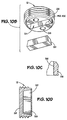
- FIGS. 10A-10D illustrate another embodiment of the RFID tag 12.
- the carrier 26 may be fabricated with a segment cavity 54, as best shown in Fig. 10B .
- An independent carrier segment 52 may be fabricated separately.
- the carrier segment 52 includes a cavity 40, as previously described and illustrated, wherein the glass bead 24 is completely surrounded by a protective fluid-like fill material 42.
- the carrier segment 52 may be inserted into the segment cavity 54 of the carrier 26.
- the carrier segment 52 may be made of the same material as the underlying carrier 26.
- the sides of the cavity 54 and carrier segment 52 may have a smooth, tapered surface. This provides a self-sealing, self-compressing mating system that works with the pressure to improve the reliability of the mating.
- the sides of the cavity 54 in which the carrier segment 52 is deposited may be ridged, as best illustrated in Fig. 10C .
- the ridges 56 may provide a mechanism to mechanically secure the carrier segment 52 within the carrier 26.
- an adhesive (not shown) may be disposed within the segment cavity 54 in addition to or instead of the employing the ridges 56 such that the carrier segment 52 may be secured within the carrier 26.
- an additional sealant material 58 may be disposed on top of the carrier segment 52 such that the carrier segment 52 is further secured within the segment cavity 54. As will be appreciated, the sealant material 58 may be omitted.
- the carrier segment 52 includes a cavity (not shown).
- the protective fluid-like fill material 42 is disposed into the cavity.
- the glass bead 24 may then be positioned within the cavity such that it is surrounded completely by the protective fluid-like fill material 42, creating a complete barrier between the surface of the bead 24 and the walls of the carrier 26, within the cavity.
- the carrier segment 52 may be heat treated. In one embodiment, the heat treatment may be approximately 1 hour at a temperature range of approximately 65°C to 120°C.
- the protective fluid-like fill material 42 expands during the heat treatment, such that the cavity is over-filled with the protective fluid-like fill material 42.
- the carrier segment 52 After the carrier segment 52 is heat treated, in may be inserted into the cavity 54 in the carrier 26.
- the application of physical force during the insertion of the carrier segment 52 into the carrier 26 will advantageously shear the excess protective fluid-like fill material 42, such that it is flush with the tapered edge of the carrier segment 52 and such that the entire cavity within the carrier segment 52 is completely filled with the protective fluid-like fill material 42, without voids being present within the cavity.
- an identification tag comprises :
- the bead comprises a glass bead.
- the bead comprises an impermeable material.
- the protective fluid-like fill material comprises a silicone gel.
- the protective fluid-like fill material comprises a silicone room-temperature vulcanizing (RTV) gel.
- RTV room-temperature vulcanizing
- the carrier comprises a thermoplastic.
- thermoplastic comprises a PolyEtherEtherKetone (PEEK).
- the electronics module comprises a dipole antenna.
- the electronics module comprises an RFID module configured to operate at a frequency in the range of approximately 125 KHz - 135 KHz.
- the electronics module comprises an integrated circuit and an antenna.
- the identification tag is configured to operate at pressures greater than or equal to 20,000 psi.
- the identification tag is configured to operate at sustained temperatures greater than or equal to 165°C.
- the identification tag comprises a membrane material disposed in the cavity on top of the protective fluid-like fill material.
- the membrane material comprises silicone.
- the membrane material comprises a fast curing silicone room-temperature vulcanizing (RTV) adhesive rubber.
- RTV room-temperature vulcanizing
- the identification tag comprises a chemically inert cap disposed in the cavity on top of the protective fluid-like fill material.
- the cap comprises a fluorosilicone material.
- the cap comprises a polytetrafluoroethylene (PTFE) material.
- PTFE polytetrafluoroethylene
- the identification tag further comprises a carrier segment configured to mate with the carrier.
- the identification tag comprises an RFID tag.
- a system comprises:
- the tool comprises a pipe configured for downhole or subsea usage.
- the electronics module is surrounded by a glass bead, and wherein the glass bead is completely surrounded by the protective fluid-like fill material.
- the tag pocket comprises threading and wherein the RFID tag is rotatably coupled into the tag pocket.
- the RFID tag is mechanically secured within the tag pocket via an adhesive or epoxy.
- the system comprises a carrier segment having the RFID tag surrounded by the protective fluid-like fill material formed therein, wherein the carrier segment is configured to be inserted into a segment cavity of the carrier.
- the RFID tag is completely embedded within the tool.
- the RFID tag is disk-shaped.
- a method of fabricating a tag comprises:
- depositing an electronics module comprises depositing a glass bead, having an electronics module therein, into the protective fluid-like fill material.
- the method further comprises depositing a membrane material into the cavity and on top of the protective fluid-like fill material.
- the method further comprises depositing a cap into the cavity and on top of the protective fluid-like fill material.
- At least partially filling comprises over-filling the cavity with the protective fluid-like fill material.
- At least partially filling the cavity comprises partially filling the cavity with the protective fluid-like fill material before depositing the electronics module into the protective fluid-like fill material, and depositing additional protective fluid-like fill material into the cavity after the electronics module is deposited.
- a method of fabricating a tag comprises:
Landscapes
- Engineering & Computer Science (AREA)
- Computer Hardware Design (AREA)
- Microelectronics & Electronic Packaging (AREA)
- Physics & Mathematics (AREA)
- General Physics & Mathematics (AREA)
- Theoretical Computer Science (AREA)
- Arrangements For Transmission Of Measured Signals (AREA)
- Earth Drilling (AREA)
- Laminated Bodies (AREA)
- Casings For Electric Apparatus (AREA)
- Measuring Fluid Pressure (AREA)
- Pressure Vessels And Lids Thereof (AREA)
Applications Claiming Priority (3)
| Application Number | Priority Date | Filing Date | Title |
|---|---|---|---|
| US12/771,766 US8690066B2 (en) | 2010-04-30 | 2010-04-30 | High temperature high pressure tag |
| EP11717371.6A EP2564360B1 (de) | 2010-04-30 | 2011-04-08 | Rf-identifizeirungsetikett fuer hohe temperatur und hohen druck |
| PCT/US2011/031808 WO2011136910A1 (en) | 2010-04-30 | 2011-04-08 | High temperature high pressure tag |
Related Parent Applications (2)
| Application Number | Title | Priority Date | Filing Date |
|---|---|---|---|
| EP11717371.6A Division EP2564360B1 (de) | 2010-04-30 | 2011-04-08 | Rf-identifizeirungsetikett fuer hohe temperatur und hohen druck |
| EP11717371.6A Division-Into EP2564360B1 (de) | 2010-04-30 | 2011-04-08 | Rf-identifizeirungsetikett fuer hohe temperatur und hohen druck |
Publications (3)
| Publication Number | Publication Date |
|---|---|
| EP3029613A2 true EP3029613A2 (de) | 2016-06-08 |
| EP3029613A3 EP3029613A3 (de) | 2017-08-23 |
| EP3029613B1 EP3029613B1 (de) | 2021-03-17 |
Family
ID=44209747
Family Applications (2)
| Application Number | Title | Priority Date | Filing Date |
|---|---|---|---|
| EP15200593.0A Not-in-force EP3029613B1 (de) | 2010-04-30 | 2011-04-08 | Hochtemperatur- und hochdrucketikett |
| EP11717371.6A Not-in-force EP2564360B1 (de) | 2010-04-30 | 2011-04-08 | Rf-identifizeirungsetikett fuer hohe temperatur und hohen druck |
Family Applications After (1)
| Application Number | Title | Priority Date | Filing Date |
|---|---|---|---|
| EP11717371.6A Not-in-force EP2564360B1 (de) | 2010-04-30 | 2011-04-08 | Rf-identifizeirungsetikett fuer hohe temperatur und hohen druck |
Country Status (4)
| Country | Link |
|---|---|
| US (2) | US8690066B2 (de) |
| EP (2) | EP3029613B1 (de) |
| BR (1) | BR112012027948B1 (de) |
| WO (1) | WO2011136910A1 (de) |
Families Citing this family (11)
| Publication number | Priority date | Publication date | Assignee | Title |
|---|---|---|---|---|
| CN203338387U (zh) * | 2013-05-17 | 2013-12-11 | 鸿富锦精密工业(深圳)有限公司 | 管状电子标签及应用该管状电子标签的箱包 |
| US9881250B2 (en) * | 2013-06-07 | 2018-01-30 | Fisher Controls International Llc | Methods and apparatus for RFID communications in a process control system |
| CN103668072B (zh) * | 2013-12-09 | 2016-02-03 | 四川省宜宾普拉斯包装材料有限公司 | 一种rfid抗干扰镀膜工艺以及仿金属镀膜塑料制品 |
| DE102015120153A1 (de) * | 2015-11-20 | 2017-05-24 | Bilz Werkzeugfabrik Gmbh & Co. Kg | Werkzeug mit RFID-Chip und Verfahren zum Befestigen eines solchen an einem Werkzeug |
| CA3010316C (en) * | 2016-01-18 | 2020-09-15 | Forum Us, Inc. | Oilfield handling tool equipment identification |
| US20170328197A1 (en) * | 2016-05-13 | 2017-11-16 | Ningbo Wanyou Deepwater Energy Science & Technolog Co.,Ltd. | Data Logger, Manufacturing Method Thereof and Real-time Measurement System Thereof |
| US20170350241A1 (en) * | 2016-05-13 | 2017-12-07 | Ningbo Wanyou Deepwater Energy Science & Technology Co.,Ltd. | Data Logger and Charger Thereof |
| EP3382238B1 (de) * | 2017-03-31 | 2020-12-16 | GEMÜ Gebr. Müller Apparatebau GmbH & Co. Kommanditgesellschaft | Membran und verfahren zur herstellung der membran |
| CN107944538B (zh) * | 2017-12-13 | 2020-10-09 | 中国石油集团川庆钻探工程有限公司安全环保质量监督检测研究院 | 一种耐高温高压uhf_rfid标签的制作工艺 |
| US11074490B2 (en) * | 2019-10-24 | 2021-07-27 | The Boeing Company | Intelligent fasteners |
| RU209864U1 (ru) * | 2021-11-17 | 2022-03-23 | Общество С Ограниченной Ответственностью "Стройпромгрупп" | Капсула для rfid-метки |
Family Cites Families (18)
| Publication number | Priority date | Publication date | Assignee | Title |
|---|---|---|---|---|
| DE4425736C2 (de) | 1994-07-21 | 1997-12-18 | Micro Sensys Gmbh | Einbauschale für Daten- oder Codeträger |
| US5731957A (en) | 1996-06-24 | 1998-03-24 | Texas Instruments Incorporated | Transponder including a fluid cushioning medium and a method for its production |
| US6100804A (en) | 1998-10-29 | 2000-08-08 | Intecmec Ip Corp. | Radio frequency identification system |
| DE20012237U1 (de) | 1999-07-26 | 2000-10-12 | Karl Storz GmbH & Co. KG, 78532 Tuttlingen | Medizinisches Instrument mit einem berührungslos lesbaren Informationsträger |
| JP3711026B2 (ja) | 2000-07-17 | 2005-10-26 | 株式会社ハネックス | Rfidタグの設置構造及びrfidタグの設置方法及びrfidタグの通信方法 |
| US20030181794A1 (en) * | 2002-01-29 | 2003-09-25 | Rini Christopher J. | Implantable sensor housing, sensor unit and methods for forming and using the same |
| DE10227683B4 (de) | 2002-06-20 | 2004-07-22 | Aeg Identifikationssysteme Gmbh | Verfahren zur Anbringung eines Transponders an einem Metallkörper und Metallkörper mit einem Transponder |
| US6885505B2 (en) * | 2002-09-04 | 2005-04-26 | Gobos Togo Inc. | Integrally bonded gobo |
| US20070215195A1 (en) * | 2006-03-18 | 2007-09-20 | Benyamin Buller | Elongated photovoltaic cells in tubular casings |
| TWI491953B (zh) * | 2006-07-18 | 2015-07-11 | 希畢克斯幻像有限公司 | 電泳顯示器 |
| US8397810B2 (en) * | 2007-06-25 | 2013-03-19 | Turbo-Chem International, Inc. | Wireless tag tracer method |
| DE102007030829A1 (de) | 2007-07-03 | 2009-01-08 | Christl Lauterbach | Flächenverkleidungsstruktur und Verfahren zum Herstellen einer Flächenverkleidungsstruktur |
| US20090079545A1 (en) * | 2007-09-26 | 2009-03-26 | Luke Chow | Flexible rfid tag device and method for constructing same |
| EP2214824A4 (de) * | 2007-11-28 | 2015-08-19 | Smart Tube Inc | Vorrichtungen, systeme und verfahren zur entnahme, stimulation, stabilisierung und analyse einer biologischen probe |
| JP5008201B2 (ja) * | 2008-05-21 | 2012-08-22 | 三智商事株式会社 | 無線icタグ |
| US8485359B2 (en) * | 2008-07-07 | 2013-07-16 | Blast Max Llc | Seal absorbent pad-RFID-bar code device for a dosing cap |
| US20100096455A1 (en) * | 2008-10-16 | 2010-04-22 | Merrick Systems Inc. | Edge mounted rfid tag |
| CA2762492C (en) * | 2009-05-22 | 2016-06-14 | Berntsen International, Inc. | System, method and monument for land surveying |
-
2010
- 2010-04-30 US US12/771,766 patent/US8690066B2/en active Active
-
2011
- 2011-04-08 EP EP15200593.0A patent/EP3029613B1/de not_active Not-in-force
- 2011-04-08 BR BR112012027948-3A patent/BR112012027948B1/pt not_active IP Right Cessation
- 2011-04-08 WO PCT/US2011/031808 patent/WO2011136910A1/en not_active Ceased
- 2011-04-08 EP EP11717371.6A patent/EP2564360B1/de not_active Not-in-force
-
2014
- 2014-02-12 US US14/179,272 patent/US9022296B2/en active Active
Non-Patent Citations (1)
| Title |
|---|
| None |
Also Published As
| Publication number | Publication date |
|---|---|
| US20140158776A1 (en) | 2014-06-12 |
| BR112012027948A2 (pt) | 2016-09-13 |
| US8690066B2 (en) | 2014-04-08 |
| EP3029613B1 (de) | 2021-03-17 |
| US20110266353A1 (en) | 2011-11-03 |
| EP3029613A3 (de) | 2017-08-23 |
| WO2011136910A1 (en) | 2011-11-03 |
| BR112012027948A8 (pt) | 2017-12-26 |
| EP2564360A1 (de) | 2013-03-06 |
| EP2564360B1 (de) | 2016-06-08 |
| US9022296B2 (en) | 2015-05-05 |
| BR112012027948B1 (pt) | 2020-12-08 |
Similar Documents
| Publication | Publication Date | Title |
|---|---|---|
| US8690066B2 (en) | High temperature high pressure tag | |
| EP2488989B1 (de) | Rfid tag für randmontage | |
| US8496184B2 (en) | Method and apparatus for packaging surface acoustic wave transponder for down-hole applications | |
| US8120497B2 (en) | RFID transponder enclosure for harsh environments | |
| US8444058B2 (en) | Embedded RFID tags and associated methods and systems | |
| US7602106B2 (en) | Piezoelectric device package and method for downhole applications | |
| US7659857B2 (en) | System and method for providing a low and narrow-profile radio frequency identification (RFID) tag | |
| CN1158622C (zh) | 用于电子信息载体的远程能量供给的结构和方法 | |
| WO2012071465A1 (en) | Thin mount rfid tagging systems | |
| US9019119B2 (en) | Surface acoustic wave transponder package for down-hole applications | |
| US8339267B2 (en) | RFID device having protective cap element and method of making | |
| US9076095B2 (en) | Extendable identification tag | |
| US20070103310A1 (en) | Asset seal device and method | |
| WO1996032696A1 (en) | Ic card and ic module | |
| US7789316B2 (en) | Electronic device, electronic apparatus mounted with electronic device, article equipped with electronic device and method of producing electronic device | |
| CN205068470U (zh) | 一种电子标签 | |
| JP2008508574A (ja) | 構成部材をカプセル化して保護するためのシステムおよび方法 | |
| EP3370190B1 (de) | Bolzen mit integriertem etikett | |
| CN219416678U (zh) | 螺栓松动状态监测装置 | |
| JP2005157736A (ja) | 無線通信モジュール,無線通信モジュール製造方法 | |
| JP2005235150A (ja) | Icタグ封入体とその製造方法 | |
| CN104156755A (zh) | 一种可多次使用高强度耐高温耐洗涤uhf洗衣标签 |
Legal Events
| Date | Code | Title | Description |
|---|---|---|---|
| PUAI | Public reference made under article 153(3) epc to a published international application that has entered the european phase |
Free format text: ORIGINAL CODE: 0009012 |
|
| AC | Divisional application: reference to earlier application |
Ref document number: 2564360 Country of ref document: EP Kind code of ref document: P |
|
| AK | Designated contracting states |
Kind code of ref document: A2 Designated state(s): AL AT BE BG CH CY CZ DE DK EE ES FI FR GB GR HR HU IE IS IT LI LT LU LV MC MK MT NL NO PL PT RO RS SE SI SK SM TR |
|
| PUAL | Search report despatched |
Free format text: ORIGINAL CODE: 0009013 |
|
| AK | Designated contracting states |
Kind code of ref document: A3 Designated state(s): AL AT BE BG CH CY CZ DE DK EE ES FI FR GB GR HR HU IE IS IT LI LT LU LV MC MK MT NL NO PL PT RO RS SE SI SK SM TR |
|
| RIC1 | Information provided on ipc code assigned before grant |
Ipc: H01Q 1/22 20060101ALI20170720BHEP Ipc: G06K 19/077 20060101AFI20170720BHEP |
|
| STAA | Information on the status of an ep patent application or granted ep patent |
Free format text: STATUS: REQUEST FOR EXAMINATION WAS MADE |
|
| 17P | Request for examination filed |
Effective date: 20180216 |
|
| STAA | Information on the status of an ep patent application or granted ep patent |
Free format text: STATUS: EXAMINATION IS IN PROGRESS |
|
| 17Q | First examination report despatched |
Effective date: 20181114 |
|
| GRAP | Despatch of communication of intention to grant a patent |
Free format text: ORIGINAL CODE: EPIDOSNIGR1 |
|
| STAA | Information on the status of an ep patent application or granted ep patent |
Free format text: STATUS: GRANT OF PATENT IS INTENDED |
|
| INTG | Intention to grant announced |
Effective date: 20201112 |
|
| GRAS | Grant fee paid |
Free format text: ORIGINAL CODE: EPIDOSNIGR3 |
|
| GRAA | (expected) grant |
Free format text: ORIGINAL CODE: 0009210 |
|
| STAA | Information on the status of an ep patent application or granted ep patent |
Free format text: STATUS: THE PATENT HAS BEEN GRANTED |
|
| AC | Divisional application: reference to earlier application |
Ref document number: 2564360 Country of ref document: EP Kind code of ref document: P |
|
| AK | Designated contracting states |
Kind code of ref document: B1 Designated state(s): AL AT BE BG CH CY CZ DE DK EE ES FI FR GB GR HR HU IE IS IT LI LT LU LV MC MK MT NL NO PL PT RO RS SE SI SK SM TR |
|
| REG | Reference to a national code |
Ref country code: GB Ref legal event code: FG4D |
|
| REG | Reference to a national code |
Ref country code: CH Ref legal event code: EP |
|
| REG | Reference to a national code |
Ref country code: DE Ref legal event code: R096 Ref document number: 602011070437 Country of ref document: DE |
|
| REG | Reference to a national code |
Ref country code: IE Ref legal event code: FG4D |
|
| REG | Reference to a national code |
Ref country code: AT Ref legal event code: REF Ref document number: 1372928 Country of ref document: AT Kind code of ref document: T Effective date: 20210415 |
|
| REG | Reference to a national code |
Ref country code: NO Ref legal event code: T2 Effective date: 20210317 |
|
| REG | Reference to a national code |
Ref country code: LT Ref legal event code: MG9D |
|
| PG25 | Lapsed in a contracting state [announced via postgrant information from national office to epo] |
Ref country code: BG Free format text: LAPSE BECAUSE OF FAILURE TO SUBMIT A TRANSLATION OF THE DESCRIPTION OR TO PAY THE FEE WITHIN THE PRESCRIBED TIME-LIMIT Effective date: 20210617 Ref country code: HR Free format text: LAPSE BECAUSE OF FAILURE TO SUBMIT A TRANSLATION OF THE DESCRIPTION OR TO PAY THE FEE WITHIN THE PRESCRIBED TIME-LIMIT Effective date: 20210317 Ref country code: FI Free format text: LAPSE BECAUSE OF FAILURE TO SUBMIT A TRANSLATION OF THE DESCRIPTION OR TO PAY THE FEE WITHIN THE PRESCRIBED TIME-LIMIT Effective date: 20210317 |
|
| REG | Reference to a national code |
Ref country code: NL Ref legal event code: MP Effective date: 20210317 |
|
| PG25 | Lapsed in a contracting state [announced via postgrant information from national office to epo] |
Ref country code: SE Free format text: LAPSE BECAUSE OF FAILURE TO SUBMIT A TRANSLATION OF THE DESCRIPTION OR TO PAY THE FEE WITHIN THE PRESCRIBED TIME-LIMIT Effective date: 20210317 Ref country code: LV Free format text: LAPSE BECAUSE OF FAILURE TO SUBMIT A TRANSLATION OF THE DESCRIPTION OR TO PAY THE FEE WITHIN THE PRESCRIBED TIME-LIMIT Effective date: 20210317 Ref country code: RS Free format text: LAPSE BECAUSE OF FAILURE TO SUBMIT A TRANSLATION OF THE DESCRIPTION OR TO PAY THE FEE WITHIN THE PRESCRIBED TIME-LIMIT Effective date: 20210317 |
|
| PG25 | Lapsed in a contracting state [announced via postgrant information from national office to epo] |
Ref country code: NL Free format text: LAPSE BECAUSE OF FAILURE TO SUBMIT A TRANSLATION OF THE DESCRIPTION OR TO PAY THE FEE WITHIN THE PRESCRIBED TIME-LIMIT Effective date: 20210317 |
|
| PG25 | Lapsed in a contracting state [announced via postgrant information from national office to epo] |
Ref country code: SM Free format text: LAPSE BECAUSE OF FAILURE TO SUBMIT A TRANSLATION OF THE DESCRIPTION OR TO PAY THE FEE WITHIN THE PRESCRIBED TIME-LIMIT Effective date: 20210317 Ref country code: EE Free format text: LAPSE BECAUSE OF FAILURE TO SUBMIT A TRANSLATION OF THE DESCRIPTION OR TO PAY THE FEE WITHIN THE PRESCRIBED TIME-LIMIT Effective date: 20210317 Ref country code: CZ Free format text: LAPSE BECAUSE OF FAILURE TO SUBMIT A TRANSLATION OF THE DESCRIPTION OR TO PAY THE FEE WITHIN THE PRESCRIBED TIME-LIMIT Effective date: 20210317 Ref country code: LT Free format text: LAPSE BECAUSE OF FAILURE TO SUBMIT A TRANSLATION OF THE DESCRIPTION OR TO PAY THE FEE WITHIN THE PRESCRIBED TIME-LIMIT Effective date: 20210317 |
|
| PG25 | Lapsed in a contracting state [announced via postgrant information from national office to epo] |
Ref country code: PT Free format text: LAPSE BECAUSE OF FAILURE TO SUBMIT A TRANSLATION OF THE DESCRIPTION OR TO PAY THE FEE WITHIN THE PRESCRIBED TIME-LIMIT Effective date: 20210719 Ref country code: PL Free format text: LAPSE BECAUSE OF FAILURE TO SUBMIT A TRANSLATION OF THE DESCRIPTION OR TO PAY THE FEE WITHIN THE PRESCRIBED TIME-LIMIT Effective date: 20210317 Ref country code: ES Free format text: LAPSE BECAUSE OF FAILURE TO SUBMIT A TRANSLATION OF THE DESCRIPTION OR TO PAY THE FEE WITHIN THE PRESCRIBED TIME-LIMIT Effective date: 20210317 Ref country code: SK Free format text: LAPSE BECAUSE OF FAILURE TO SUBMIT A TRANSLATION OF THE DESCRIPTION OR TO PAY THE FEE WITHIN THE PRESCRIBED TIME-LIMIT Effective date: 20210317 Ref country code: RO Free format text: LAPSE BECAUSE OF FAILURE TO SUBMIT A TRANSLATION OF THE DESCRIPTION OR TO PAY THE FEE WITHIN THE PRESCRIBED TIME-LIMIT Effective date: 20210317 Ref country code: IS Free format text: LAPSE BECAUSE OF FAILURE TO SUBMIT A TRANSLATION OF THE DESCRIPTION OR TO PAY THE FEE WITHIN THE PRESCRIBED TIME-LIMIT Effective date: 20210717 |
|
| REG | Reference to a national code |
Ref country code: DE Ref legal event code: R097 Ref document number: 602011070437 Country of ref document: DE |
|
| PG25 | Lapsed in a contracting state [announced via postgrant information from national office to epo] |
Ref country code: LU Free format text: LAPSE BECAUSE OF NON-PAYMENT OF DUE FEES Effective date: 20210408 |
|
| REG | Reference to a national code |
Ref country code: BE Ref legal event code: MM Effective date: 20210430 |
|
| PLBE | No opposition filed within time limit |
Free format text: ORIGINAL CODE: 0009261 |
|
| STAA | Information on the status of an ep patent application or granted ep patent |
Free format text: STATUS: NO OPPOSITION FILED WITHIN TIME LIMIT |
|
| PG25 | Lapsed in a contracting state [announced via postgrant information from national office to epo] |
Ref country code: DK Free format text: LAPSE BECAUSE OF FAILURE TO SUBMIT A TRANSLATION OF THE DESCRIPTION OR TO PAY THE FEE WITHIN THE PRESCRIBED TIME-LIMIT Effective date: 20210317 Ref country code: LI Free format text: LAPSE BECAUSE OF NON-PAYMENT OF DUE FEES Effective date: 20210430 Ref country code: MC Free format text: LAPSE BECAUSE OF FAILURE TO SUBMIT A TRANSLATION OF THE DESCRIPTION OR TO PAY THE FEE WITHIN THE PRESCRIBED TIME-LIMIT Effective date: 20210317 Ref country code: AL Free format text: LAPSE BECAUSE OF FAILURE TO SUBMIT A TRANSLATION OF THE DESCRIPTION OR TO PAY THE FEE WITHIN THE PRESCRIBED TIME-LIMIT Effective date: 20210317 Ref country code: CH Free format text: LAPSE BECAUSE OF NON-PAYMENT OF DUE FEES Effective date: 20210430 |
|
| 26N | No opposition filed |
Effective date: 20211220 |
|
| PG25 | Lapsed in a contracting state [announced via postgrant information from national office to epo] |
Ref country code: SI Free format text: LAPSE BECAUSE OF FAILURE TO SUBMIT A TRANSLATION OF THE DESCRIPTION OR TO PAY THE FEE WITHIN THE PRESCRIBED TIME-LIMIT Effective date: 20210317 |
|
| PG25 | Lapsed in a contracting state [announced via postgrant information from national office to epo] |
Ref country code: IE Free format text: LAPSE BECAUSE OF NON-PAYMENT OF DUE FEES Effective date: 20210408 |
|
| PG25 | Lapsed in a contracting state [announced via postgrant information from national office to epo] |
Ref country code: IS Free format text: LAPSE BECAUSE OF FAILURE TO SUBMIT A TRANSLATION OF THE DESCRIPTION OR TO PAY THE FEE WITHIN THE PRESCRIBED TIME-LIMIT Effective date: 20210717 |
|
| PG25 | Lapsed in a contracting state [announced via postgrant information from national office to epo] |
Ref country code: BE Free format text: LAPSE BECAUSE OF NON-PAYMENT OF DUE FEES Effective date: 20210430 |
|
| REG | Reference to a national code |
Ref country code: AT Ref legal event code: UEP Ref document number: 1372928 Country of ref document: AT Kind code of ref document: T Effective date: 20210317 |
|
| REG | Reference to a national code |
Ref country code: FR Ref legal event code: PLFP Year of fee payment: 13 |
|
| PGFP | Annual fee paid to national office [announced via postgrant information from national office to epo] |
Ref country code: NO Payment date: 20230322 Year of fee payment: 13 Ref country code: FR Payment date: 20230321 Year of fee payment: 13 |
|
| PG25 | Lapsed in a contracting state [announced via postgrant information from national office to epo] |
Ref country code: HU Free format text: LAPSE BECAUSE OF FAILURE TO SUBMIT A TRANSLATION OF THE DESCRIPTION OR TO PAY THE FEE WITHIN THE PRESCRIBED TIME-LIMIT; INVALID AB INITIO Effective date: 20110408 Ref country code: CY Free format text: LAPSE BECAUSE OF FAILURE TO SUBMIT A TRANSLATION OF THE DESCRIPTION OR TO PAY THE FEE WITHIN THE PRESCRIBED TIME-LIMIT Effective date: 20210317 |
|
| PGFP | Annual fee paid to national office [announced via postgrant information from national office to epo] |
Ref country code: IT Payment date: 20230322 Year of fee payment: 13 Ref country code: GB Payment date: 20230322 Year of fee payment: 13 |
|
| PG25 | Lapsed in a contracting state [announced via postgrant information from national office to epo] |
Ref country code: GR Free format text: LAPSE BECAUSE OF FAILURE TO SUBMIT A TRANSLATION OF THE DESCRIPTION OR TO PAY THE FEE WITHIN THE PRESCRIBED TIME-LIMIT Effective date: 20210317 |
|
| PGFP | Annual fee paid to national office [announced via postgrant information from national office to epo] |
Ref country code: DE Payment date: 20230321 Year of fee payment: 13 |
|
| PGFP | Annual fee paid to national office [announced via postgrant information from national office to epo] |
Ref country code: AT Payment date: 20230322 Year of fee payment: 13 |
|
| PG25 | Lapsed in a contracting state [announced via postgrant information from national office to epo] |
Ref country code: MK Free format text: LAPSE BECAUSE OF FAILURE TO SUBMIT A TRANSLATION OF THE DESCRIPTION OR TO PAY THE FEE WITHIN THE PRESCRIBED TIME-LIMIT Effective date: 20210317 |
|
| PG25 | Lapsed in a contracting state [announced via postgrant information from national office to epo] |
Ref country code: MT Free format text: LAPSE BECAUSE OF FAILURE TO SUBMIT A TRANSLATION OF THE DESCRIPTION OR TO PAY THE FEE WITHIN THE PRESCRIBED TIME-LIMIT Effective date: 20210317 |
|
| REG | Reference to a national code |
Ref country code: DE Ref legal event code: R119 Ref document number: 602011070437 Country of ref document: DE |
|
| REG | Reference to a national code |
Ref country code: AT Ref legal event code: MM01 Ref document number: 1372928 Country of ref document: AT Kind code of ref document: T Effective date: 20240408 |
|
| GBPC | Gb: european patent ceased through non-payment of renewal fee |
Effective date: 20240408 |
|
| PG25 | Lapsed in a contracting state [announced via postgrant information from national office to epo] |
Ref country code: DE Free format text: LAPSE BECAUSE OF NON-PAYMENT OF DUE FEES Effective date: 20241105 |
|
| PG25 | Lapsed in a contracting state [announced via postgrant information from national office to epo] |
Ref country code: NO Free format text: LAPSE BECAUSE OF NON-PAYMENT OF DUE FEES Effective date: 20240430 |
|
| PG25 | Lapsed in a contracting state [announced via postgrant information from national office to epo] |
Ref country code: GB Free format text: LAPSE BECAUSE OF NON-PAYMENT OF DUE FEES Effective date: 20240408 |
|
| PG25 | Lapsed in a contracting state [announced via postgrant information from national office to epo] |
Ref country code: FR Free format text: LAPSE BECAUSE OF NON-PAYMENT OF DUE FEES Effective date: 20240430 |
|
| PG25 | Lapsed in a contracting state [announced via postgrant information from national office to epo] |
Ref country code: AT Free format text: LAPSE BECAUSE OF NON-PAYMENT OF DUE FEES Effective date: 20240408 |
|
| PG25 | Lapsed in a contracting state [announced via postgrant information from national office to epo] |
Ref country code: NO Free format text: LAPSE BECAUSE OF NON-PAYMENT OF DUE FEES Effective date: 20240430 Ref country code: GB Free format text: LAPSE BECAUSE OF NON-PAYMENT OF DUE FEES Effective date: 20240408 Ref country code: FR Free format text: LAPSE BECAUSE OF NON-PAYMENT OF DUE FEES Effective date: 20240430 Ref country code: DE Free format text: LAPSE BECAUSE OF NON-PAYMENT OF DUE FEES Effective date: 20241105 Ref country code: AT Free format text: LAPSE BECAUSE OF NON-PAYMENT OF DUE FEES Effective date: 20240408 |
|
| PG25 | Lapsed in a contracting state [announced via postgrant information from national office to epo] |
Ref country code: IT Free format text: LAPSE BECAUSE OF NON-PAYMENT OF DUE FEES Effective date: 20240408 |
|
| PG25 | Lapsed in a contracting state [announced via postgrant information from national office to epo] |
Ref country code: TR Free format text: LAPSE BECAUSE OF FAILURE TO SUBMIT A TRANSLATION OF THE DESCRIPTION OR TO PAY THE FEE WITHIN THE PRESCRIBED TIME-LIMIT Effective date: 20210317 |